CCNA Wireless 200-355 Official Cert Guide (2016)
Chapter 6. Understanding 802.11 Frame Types
This chapter covers the following topics:
![]() 802.11 Frame Format—This section describes the basic format of wireless LAN frames and the addressing fields they contain.
802.11 Frame Format—This section describes the basic format of wireless LAN frames and the addressing fields they contain.
![]() Accessing the Wireless Medium—This section explains the mechanisms that wireless devices must use to contend for use of a channel when transmitting.
Accessing the Wireless Medium—This section explains the mechanisms that wireless devices must use to contend for use of a channel when transmitting.
![]() 802.11 Frame Types—This section discusses the three basic types of 802.11 frames and their use.
802.11 Frame Types—This section discusses the three basic types of 802.11 frames and their use.
![]() Client Housekeeping—This section discusses many common operations between a wireless client and an access point, based on 802.11 management frames.
Client Housekeeping—This section discusses many common operations between a wireless client and an access point, based on 802.11 management frames.
This chapter covers the following exam topics:
![]() 2.3—Describe 802.11 fundamentals
2.3—Describe 802.11 fundamentals
![]() 2.3e—Frame types
2.3e—Frame types
![]() 2.3e(i)—Management
2.3e(i)—Management
![]() 2.3e(ii)—Control
2.3e(ii)—Control
![]() 2.3e(iii)—Data
2.3e(iii)—Data
Wireless networks based on the 802.11 standard operate in a very organized and controlled fashion. The standard defines the frame format and frame types that access points (APs) and clients must use to communicate successfully. Before a device transmits on a channel, it must cooperate with all other devices and contend for use of the channel. This chapter covers these topics and the choreography that occurs between an AP and its clients.
“Do I Know This Already?” Quiz
The “Do I Know This Already?” quiz allows you to assess whether you should read this entire chapter thoroughly or jump to the “Exam Preparation Tasks” section. If you are in doubt about your answers to these questions or your own assessment of your knowledge of the topics, read the entire chapter. Table 6-1 lists the major headings in this chapter and their corresponding “Do I Know This Already?” quiz questions. You can find the answers in Appendix A, “Answers to the ‘Do I Know This Already?’ Quizzes.”
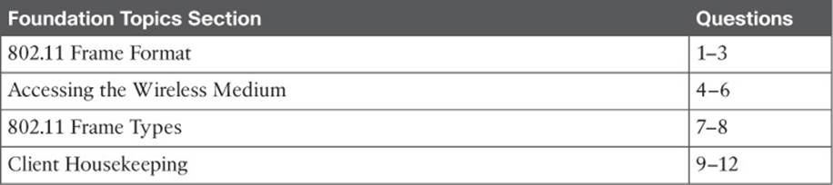
Table 6-1 “Do I Know This Already?” Section-to-Question Mapping
Caution
The goal of self-assessment is to gauge your mastery of the topics in this chapter. If you do not know the answer to a question or are only partially sure of the answer, you should mark that question as wrong for purposes of the self-assessment. Giving yourself credit for an answer you correctly guess skews your self-assessment results and might provide you with a false sense of security.
1. Which one of the following is the maximum number of address fields defined in an 802.11 frame header?
a. 1
b. 2
c. 3
d. 4
2. Every 802.11 frame contains 2 flag bits that designate whether the frame is headed to or from which one of the following?
a. The AP
b. The DS
c. The BSS
d. The ESS
3. The Address1 field in an 802.11 frame always contains which one of the following?
a. The transmitter address (TA)
b. The BSSID
c. The AP’s base radio MAC address
d. The receiver address (RA)
4. To access a wireless channel, 802.11 devices participate in which one of the following?
a. DCF
b. GCF
c. LCM
d. BSD
5. A wireless client maintains a NAV value that is used for which one of the following purposes?
a. To navigate the frame through the ESS
b. To identify the MAC address of the next client to transmit
c. To predict when the channel might become free
d. To set the priority of the client’s ability to transmit
6. Which one of the following specifies the default amount of time between successive 802.11 data frames?
a. CCA
b. IBSS
c. SIFS
d. DIFS
7. Which one of the following is the frame type sent to discover APs within the signal range of a wireless client?
a. Scan
b. Probe
c. Beacon
d. Discovery
8. An ACK frame is an example of which one of the following 802.11 frame types?
a. Management
b. Control
c. Administration
d. Data
9. A wireless AP advertises mandatory data rates of 1, 2, 5.5, and 11 Mbps. Which of the following represent client data rates that can successfully join the BSS? (Choose all that apply.)
a. Mandatory: 1 Mbps, Supported: 2, 5.5, 11 Mbps
b. Mandatory: 2 Mbps, Supported: 1, 5.5, 11 Mbps
c. Mandatory: 1 Mbps, Supported: None
d. Mandatory: 5, 11 Mbps; Supported: None
10. In a passive scan, a wireless client uses which one of the following methods to discover nearby APs?
a. Beacons
b. Probe requests
c. ACKs
d. Discovers
11. When a client attempts to join a BSS, which one of the following frame types is sent first?
a. Beacon
b. Rate request
c. Association request
d. Authentication request
12. Which one of the following frame types does a client use to roam seamlessly from one BSS to another, within the same ESS and the same SSID?
a. Association request
b. Disassociation
c. Reassociation
d. Roam request
Foundation Topics
802.11 Frame Format
To understand more about 802.11 frames and how they are transported, it might be useful to compare them with the familiar 802.3 frames.
Ethernet devices based on IEEE 802.3 send and receive frames in the format shown in Figure 6-1. The sender and the intended recipient of a frame are identified by two MAC addresses—a source and a destination. The source address is not used to deliver the frame; rather, it is used for any return traffic that is sent back to the source. When the recipient receives a frame that has its own MAC address as the destination, the frame is then accepted and processed.
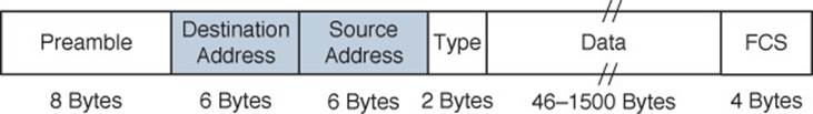
Figure 6-1 IEEE 802.3 Ethernet Frame Format
Suppose that the source and destination hosts are connected by a switched network, as shown in Figure 6-2. The switch that connects the two hosts forwards frames between them as needed, but it does not intervene or actively participate in the exchange. In other words, neither host has to be aware of the switch’s existence at all. Frames enter and exit a switch simply because hosts are connected to it through wires or cables. The switch silently forwards the frames based on the destination MAC addresses and the device locations it has learned from the source MAC addresses.
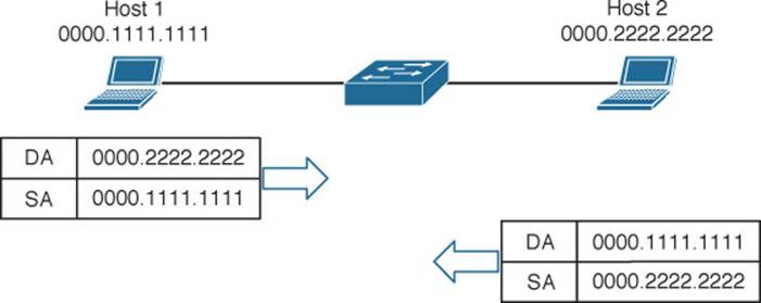
Figure 6-2 Forwarding 802.3 Frames in a Switched Network
In contrast, the APs in an 802.11 network are active participants. Recall from Chapter 5, “Wireless LAN Topologies,” that an AP acts as the central “hub” or manager of a basic service set (BSS). With the absence of wired connections, a client must join or associate with a specific wireless network by first getting permission from the AP. Then the client must send and receive every frame through the AP or coordinate with the AP for direct client-to-client communication to use 802.11z, Extensions to Direct Link Setup (DLS).
IEEE 802.11 networks are based on traditional MAC addresses. Each client’s radio interface must have a unique MAC address so that frames can be sent from and received to that address. To direct frames through an AP, the AP must also have a MAC address of its own. Wireless clients know the AP’s address as the BSS identifier (BSSID), which must be included in each frame sent to the AP.
Figure 6-3 shows the basic format of 802.11 frames at the MAC layer, which can carry a maximum payload of 2304 bytes in length. The frame begins with a 2-byte Frame Control field, which identifies such things as the frame type and the direction in which the frame is traveling as it moves from one wireless device to another.
![]()
Figure 6-3 IEEE 802.11 Frame Format
Tip
The 802.11n and 802.11ac amendments allow frames to be aggregated and sent as a single unit, to reduce overhead and increase throughput.
Consider a common scenario where several wireless clients are associated with an AP. This is not a standalone BSS—the AP also connects to an upstream distribution system (DS). Most of the time, wireless frames pass through the AP, either coming from clients toward the DS or coming from the DS toward the clients. Frame motion is indicated by 2 bits, To DS and From DS, contained in the 802.11 frame header. On the surface, it seems that frames travel in only one of two directions, relative to the DS, as shown in the simple examples of Figure 6-4.
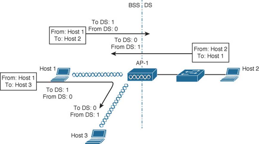
Figure 6-4 Some Example 802.11 Frames Moving to and from the DS
With just two frame directions to indicate, a single bit would suffice. Why are there two different direction bits in the frame header? There are two other special cases where frames are destined for something other than a specific wireless client or somewhere in the DS, as shown in Figure 6-5. This gives a total of four possible destinations, or 2 bits’ worth of direction values.
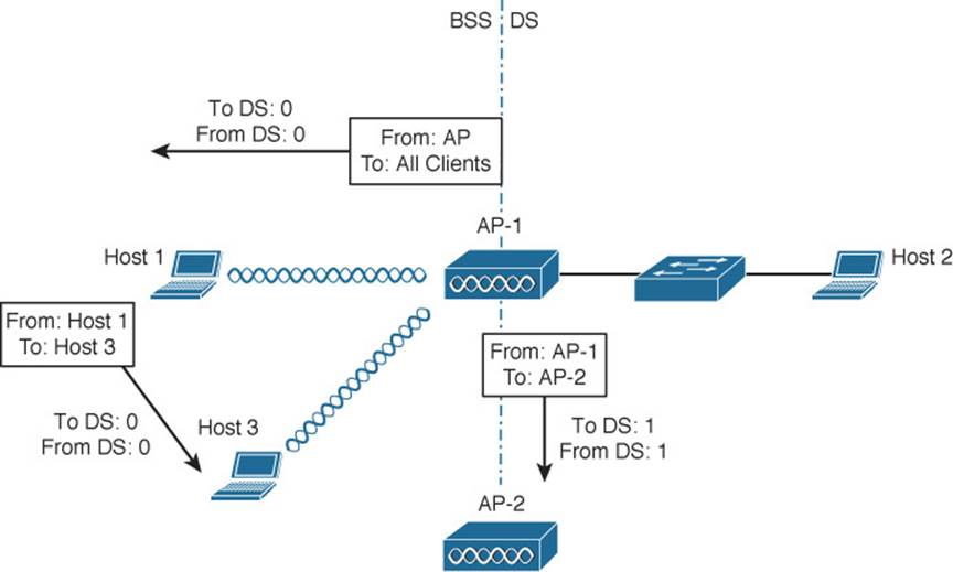
Figure 6-5 Examples of 802.1.1 Frames That Are Not Moving to and from the DS
One special case commonly occurs when a frame is sourced or destined from a location that cannot be clearly defined in relation to the DS. In the following examples, both the To DS and From DS bits are set to 0:
![]() An AP sends a management or control frame, which is broadcast to all wireless clients in the BSS. The AP, and not the DS, is the source of the frame.
An AP sends a management or control frame, which is broadcast to all wireless clients in the BSS. The AP, and not the DS, is the source of the frame.
![]() A client sends a management frame to an AP, such that the AP itself is the destination.
A client sends a management frame to an AP, such that the AP itself is the destination.
![]() One client sends a frame directly to another client via DLS. The frame is not destined for the AP or the DS.
One client sends a frame directly to another client via DLS. The frame is not destined for the AP or the DS.
The other special case is related to mesh AP networks, where frames are relayed from AP to AP over wireless backhaul links. A backhaul link is neither in the BSS nor in the DS, so both direction bits are set to 1.
802.11 Frame Addressing
From an addressing viewpoint, an 802.11 frame header can contain up to four different address fields. In Figure 6-3, you can see them listed with the rather generic names Address1 through Address4. Wireless frames are always sent from a transmitting device to a receiving device. Therefore, each frame header must contain a transmitter address (TA) and a receiver address (RA). The Address1 field always contains the RA, though its exact contents may vary depending on where the frame is headed. Likewise, Address2 always contains the TA.
Address3 contains the final destination address (DA) when the RA is not the final recipient. For example, when a wireless client sends a frame to a destination on the DS, the frame is transmitted from the client’s wireless adapter, is received by the AP, but still needs to be forwarded on to the final destination on the DS. Likewise, Address3 can contain the original source address (SA) when the TA is not the originator. Consider a frame sent from a device on the DS to a wireless client. When the frame is sent over the wireless medium, the AP’s radio is the transmitter address, but the AP did not originate the frame—a device on the DS did.
Address4 is not present in the frame unless the frame is being transported from one AP to another AP across a wireless link. In that case, the frame has to carry the original SA and DA, in addition to the MAC addresses of a receiver (RA) and transmitter (TA)—the APs relaying the frame over the air.
Table 6-2 lists the possible combinations of frame direction bits, along with the four address field contents. You should become familiar with frame addressing, as the CCNA Wireless exam may cover it. Try to break the table down into parts. First, get comfortable with the To/From DS bits and the reasons behind the frame directions. Next, think about what happens to a frame each step along the way as it travels from its source to its destination. Does it stop at the AP? Does the AP relay it to or from a more distant location? Remember that Address1 and Address2 are always the receiver and transmitter MAC addresses, respectively. Address3 will contain the address of an additional hop, if one is needed.
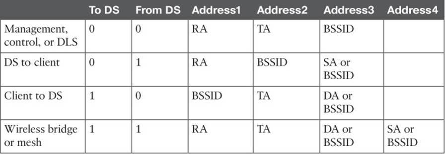
Table 6-2 802.11 Frame Header Direction and Addressing
Figure 6-6 shows two example frames and their address fields. Frame1 at the top is being sent from Host1 to Host2, while Frame2 at the bottom is coming from Host2 to Host1. Fictitious MAC addresses are used for clarity.
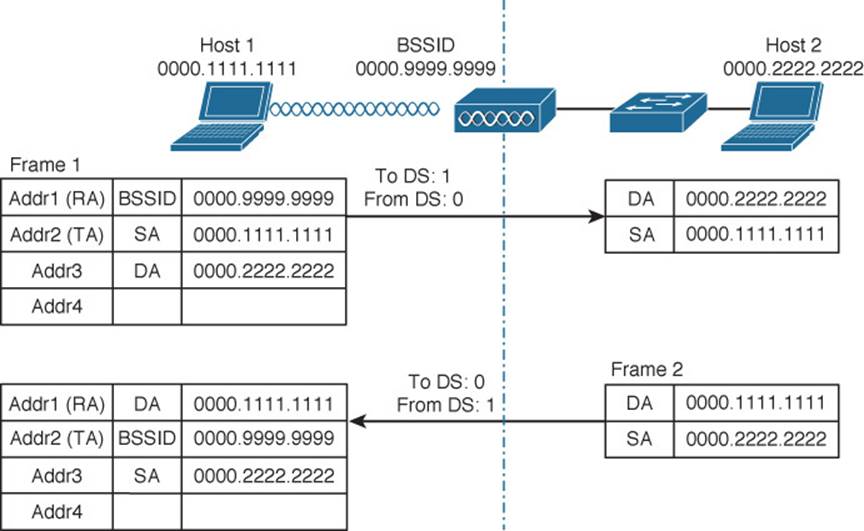
Figure 6-6 Examples of 802.11 Frame Addressing
Host1 is sending the frame through the AP to the DS, so the Address1 (RA) contains the BSSID 0000.9999.9999. Frame1 is sourced or transmitted by Host1, so the Address2 (TA) field contains Host1’s MAC address, 0000.1111.1111. The frame must pass through the AP, so Host1 populates Address3 with the destination address of Host2, 0000.2222.2222. Once the AP receives Frame1, it finds that Host2 is located on the DS, so the wireless frame is converted into an 802.3 wired frame. The original source and destination addresses are copied into the new frame so that it can be forwarded on to Host2.
On the return trip, Host2 fills in the source and destination addresses of Frame2 in 802.3 format. The switch forwards the frame to the AP, which knows that the destination (Host1) is located within the wireless BSS. The AP populates Address1 (RA) with the destination address of Host1. The AP is transmitting the frame, so Address2 (TA) contains the BSSID. The address of the original source, Host2, is copied into the Address3 field.
Accessing the Wireless Medium
Once a wireless device has data to send, it must access the network medium and try to send it. Remember that a wireless channel is a shared medium and that every device trying to use it must share the airtime and contend for its use. There is no centralized function that coordinates the use of a wireless channel. Instead, this effort is distributed to each device that uses a channel. This is known as a distributed coordination function (DCF).
With a shared medium, such as wired Ethernet or wireless, two or more stations transmitting at the same time can cause collisions. A collision ruins the transmitted data, wastes time on the medium, and causes the data to be retransmitted—wasting even more time. When full-duplex operation isn’t possible, some collisions are inevitable; therefore, every device should make its best attempt to mitigate and/or hopefully prevent collisions in the first place.
Carrier Sense
Devices based on the 802.3 and 802.11 standards must use the carrier sense multiple access (CSMA) technique to determine if the media is available before transmitting. Wired devices are able to sense an electrical signal on the wire to detect a transmission already in progress. Wireless devices can use a two-fold process to detect a channel in use:
![]() Physical carrier sense—When a wireless client is not transmitting, it can listen to the channel to overhear any other transmissions that might be occurring. In the case of an 802.11n or 802.11ac device, a high-bandwidth frame may involve multiple channels simultaneously, so any secondary channels must also be checked. If it overhears a frame that is destined for its own MAC address, then it receives the frame for processing. Otherwise, if a transmission is detected but the client cannot read the transmitter’s MAC address in the header, the client decides that the channel is busy. This process is also known as clear channel assessment (CCA). While CCA is effective, it isn’t a proactive approach and must be used in conjunction with other methods.
Physical carrier sense—When a wireless client is not transmitting, it can listen to the channel to overhear any other transmissions that might be occurring. In the case of an 802.11n or 802.11ac device, a high-bandwidth frame may involve multiple channels simultaneously, so any secondary channels must also be checked. If it overhears a frame that is destined for its own MAC address, then it receives the frame for processing. Otherwise, if a transmission is detected but the client cannot read the transmitter’s MAC address in the header, the client decides that the channel is busy. This process is also known as clear channel assessment (CCA). While CCA is effective, it isn’t a proactive approach and must be used in conjunction with other methods.
![]() Virtual carrier sense—When a wireless client transmits a frame, it must include a duration field in the Duration/ID frame header field. The duration indicates how much time is required for the whole frame, plus an interframe gap, plus a return ACK frame, to be sent over the channel. This effectively reserves the channel for that length of time. As long as other wireless clients can overhear a frame and its header, they can predict how long they should wait for the frame to complete. Figure 6-7 depicts the frame duration field and its relationship to the frame length in time.
Virtual carrier sense—When a wireless client transmits a frame, it must include a duration field in the Duration/ID frame header field. The duration indicates how much time is required for the whole frame, plus an interframe gap, plus a return ACK frame, to be sent over the channel. This effectively reserves the channel for that length of time. As long as other wireless clients can overhear a frame and its header, they can predict how long they should wait for the frame to complete. Figure 6-7 depicts the frame duration field and its relationship to the frame length in time.
![]()
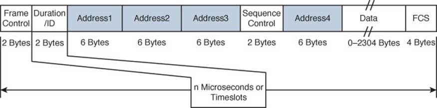
Figure 6-7 802.11 Frame Duration Field
Each wireless client must maintain a network allocation vector (NAV) timer that is used to predict when the channel will become free. Each time a frame is overheard on the channel, its Duration value is loaded into the NAV. The NAV timer then counts down while the client waits to transmit.
The NAV timer must be at zero before a client can contend for use of the channel. That sounds simple, but the contention process is still a bit more complex. Sensing the carrier alone can alert a client when the medium is quiet and available—except that every client on the channel will come to the same conclusion at the same time! If multiple clients have frames to transmit and all decide that the channel is free at the same time, collisions are still likely.
Collision Avoidance
The 802.3 and 802.11 standards differ when it comes to dealing with collisions. Wired devices can detect collisions in real time so that they can back off and wait a random time to try again. This is known as CSMA/CD (collision detection).
Wireless devices always operate in half-duplex mode, which prevents a client from receiving signals on a channel while it is transmitting. This means that a transmitting wireless client can’t detect when a collision occurs at all. Therefore, 802.11 devices must try to avoid collisions in the first place, resulting in the CSMA/CA (collision avoidance) scheme.
Wireless clients avoid collisions by backing off and waiting a random time before transmitting. Here, time is measured in two ways: by timeslot, a counting tempo at regular intervals, and by a unit called the SIFS, which is defined later in this section. If a client has a frame to transmit, it must wait until the channel is quiet, then it chooses a random number (0 to 31) of timeslots to use as a backoff timer. If there are multiple clients with frames ready to transmit, their random backoff timer values will lessen the likelihood that they will contend to use a channel at the same time. In fact, the range of random timer values is called the contention window.
If the channel becomes busy before the backoff timer reaches zero, the timer is paused and the overheard frame duration value is added to the NAV. The waiting client can transmit only when every timer mechanism has expired and the channel is available.
Believe it or not, there is one more timing scheme that controls frame transmission. The 802.11 standard defines a few different interframe space periods that provide a safety cushion between frames. These periods of silence give the channel enough time for signals to dampen out—especially when multipath is involved and some reflected copies take longer to propagate than others.
Several different interframe space periods are used, according to the type and priority of the frame being transmitted:
![]() Reduced interframe space (RIFS)—The shortest period of time, used before each data frame during a burst of 802.11n frames; not used by 802.11ac because it allows aggregated frames instead
Reduced interframe space (RIFS)—The shortest period of time, used before each data frame during a burst of 802.11n frames; not used by 802.11ac because it allows aggregated frames instead
![]() Short interframe space (SIFS)—Used between data frames and frame acknowledgements or CTS 802.11g protection mode control frames
Short interframe space (SIFS)—Used between data frames and frame acknowledgements or CTS 802.11g protection mode control frames
![]() Distributed interframe space (DIFS)—The default period used after most standard priority frame types
Distributed interframe space (DIFS)—The default period used after most standard priority frame types
![]() Extended interframe space (EIFS)—The longest period of time, used after collisions and before retransmitted frames
Extended interframe space (EIFS)—The longest period of time, used after collisions and before retransmitted frames
Tip
If you feel confused about all the timer mechanisms, try to remember this simple rule. Before a device can transmit on a channel, it must do the following:
1. Wait until the channel is quiet for a DIFS period.
2. Choose a random number and count down the backoff timer.
3. Listen during the countdown; stop counting if another station’s transmission is heard; resume counting after the channel has been quiet for a DIFS period.
4. Once the countdown reaches zero and the channel is clear, the client may transmit.
Assuming all of the carrier sense and collision avoidance methods have worked, how does a transmitting client know that the frame it just sent arrived in good condition? During transmission, the receiver must be off, so there is no way to listen to the channel. Instead, every client must rely on a very rudimentary feedback mechanism. Each time a client receives a unicast frame, it must send a unicast acknowledgement frame back to the sender. The 802.11 standard requires this one-to-one response for every frame received, except in the case of 802.11n, 802.11ac, and 802.11e (WMM) blocks of frames, which require one acknowledgement for a whole block of frames.
If a transmitted frame fails and is not acknowledged, the sending client must try again by retransmitting the frame. The client chooses a new backoff timer value from a contention window that is double the previous range. In effect, this relaxes the conditions on the channel to give the retransmitted frame a better chance of surviving. With every failed attempt, the contention window is doubled, up to a maximum of 1023 timeslots.
Figure 6-8 shows an example of the DCF operation within a wireless cell.
![]()
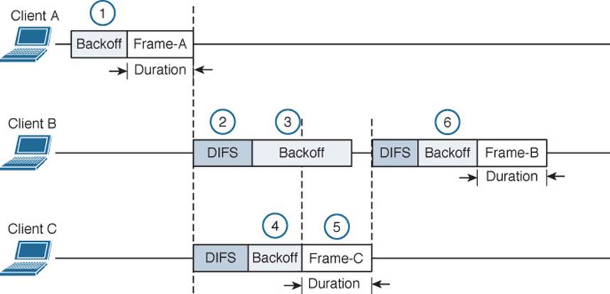
Figure 6-8 Avoiding Collisions with the DCF Process
The following sequence of events occurs:
1. Client A has been waiting at least a DIFS period and determines that no other devices are transmitting. Client A waits a random backoff timer period before transmitting Frame-A. The frame’s duration is advertised in the header’s duration field.
2. Client B has a frame to transmit. It must wait until Client A’s frame is completed and then wait until a DIFS period has expired.
3. Client B waits a random backoff time before attempting to transmit.
4. While Client B is waiting, Client C has a frame to transmit. Like Client B, Client C must wait until the DIFS period after Client A’s transmission has elapsed. Client C then listens and detects that no one else is transmitting. It then waits a random backoff time that is shorter than Client B’s backoff timer.
5. Client C transmits a frame and advertises the frame duration in the duration field.
6. Client B must now wait the duration of Client C’s frame plus a DIFS period plus the remainder of its own backoff timer before attempting to transmit.
802.11 Frame Types
The 802.11 standard defines three different frame types that can be used:
![]()
![]() Management frames
Management frames
![]() Control frames
Control frames
![]() Data frames
Data frames
The frame type is identified by a 2-bit Type field and a 4-bit SubType field in the Frame Control portion of the header. This implies that each of the three frame types can have several different subtypes that perform various functions. The frame types and their most common subtypes are discussed in the following sections.
Management Frames
Management frames are used to advertise a BSS and its capabilities and to manage clients as they join or leave the BSS. For example, 802.11ac management frames include very high throughput (VHT) capabilities such as channel width, guard interval, beamforming, and MCS support. Management frames are also used to manage clients as they join or leave the BSS. A client must first locate a candidate BSS to join, authenticate itself to an AP, and associate itself with the BSS.
Although there are 14 different management frame subtypes available, you should become familiar with just the following for the CCNA Wireless exam:
![]() Beacon—The AP broadcasts this frame to advertise the BSS, the data rates necessary and allowed in the BSS, an optional security set identifier (SSID) string, and vendor-specific information when necessary. Beacons are sent to any and all devices in the BSA about ten times per second (100-ms intervals). If the AP supports multiple SSIDs, a different beacon is broadcast for each SSID.
Beacon—The AP broadcasts this frame to advertise the BSS, the data rates necessary and allowed in the BSS, an optional security set identifier (SSID) string, and vendor-specific information when necessary. Beacons are sent to any and all devices in the BSA about ten times per second (100-ms intervals). If the AP supports multiple SSIDs, a different beacon is broadcast for each SSID.
A wireless device can learn about BSSs within range by listening to the beacons that are received. This is known as passive scanning.
![]() Probe—A wireless device can send probe request frames to ask any APs within range or a specific AP to provide information about their BSSs. An AP answers by sending a probe response that contains most of the beacon information. Probing for BSS information is known as active scanning.
Probe—A wireless device can send probe request frames to ask any APs within range or a specific AP to provide information about their BSSs. An AP answers by sending a probe response that contains most of the beacon information. Probing for BSS information is known as active scanning.
![]() Authentication and deauthentication—To join a BSS, a wireless device must first send an authentication request frame to an AP. The AP can support either Open System authentication, where any valid 802.11 device is authenticated without any other sort of verification, or shared key authentication, where a valid 802.11 device must exchange a Wired Equivalent Privacy (WEP) key that matches the key used by the AP. The AP sends the result of the authentication in an authentication response frame.
Authentication and deauthentication—To join a BSS, a wireless device must first send an authentication request frame to an AP. The AP can support either Open System authentication, where any valid 802.11 device is authenticated without any other sort of verification, or shared key authentication, where a valid 802.11 device must exchange a Wired Equivalent Privacy (WEP) key that matches the key used by the AP. The AP sends the result of the authentication in an authentication response frame.
If a device wants to leave the authenticated state, it can send a deauthentication frame to the AP. However, the AP can force a device out of the authenticated state by sending it a deauthentication frame.
Tip
It might seem odd that Open System and WEP are the only two authentication methods offered in authentication request frames. The intent is to simply screen devices to make sure they are 802.11 compliant. Beyond that, wireless networks can offer robust authentication methods through a different method of frame exchanges. Those methods are covered in Chapter 14, “Wireless Security Fundamentals.”
![]() Association, disassociation, and reassociation—Once a device is authenticated, it can send an association request frame to the AP to ask permission to join the BSS. If the device supports compatible parameters and is allowed to join, then the AP will reply with an association response frame, along with a unique association identifier (AID) for that client.
Association, disassociation, and reassociation—Once a device is authenticated, it can send an association request frame to the AP to ask permission to join the BSS. If the device supports compatible parameters and is allowed to join, then the AP will reply with an association response frame, along with a unique association identifier (AID) for that client.
If a device wants to gracefully leave a BSS, it can send a disassociation frame to the AP. An AP can also decide to drop a client by sending it a disassociation frame.
When a client wants to leave one BSS for another, while staying within the same SSID, it can send a reassociation request frame to the new AP. In effect, the client is attempting to reassociate with the SSID, not an AP. The new AP responds with a reassociation response frame. (Moving from one BSS to another is covered in greater detail in Chapter 12, “Understanding Roaming.”)
![]() Action—An action frame provides a way to communicate an extended management action to be taken. For example, in the 802.11k amendment, a wireless station can use action frames to request radio measurement information from other devices, as well as a report of neighboring APs to make its roaming decisions more efficient. The 802.11v amendment uses action frames to allow network-assisted client power savings. The 802.11y amendment leverages action frames to allow an AP to announce an impending channel change or channel width change to its associated clients.
Action—An action frame provides a way to communicate an extended management action to be taken. For example, in the 802.11k amendment, a wireless station can use action frames to request radio measurement information from other devices, as well as a report of neighboring APs to make its roaming decisions more efficient. The 802.11v amendment uses action frames to allow network-assisted client power savings. The 802.11y amendment leverages action frames to allow an AP to announce an impending channel change or channel width change to its associated clients.
Control Frames
Control frames are used to gain control of and to help deliver data over a channel. Control frames contain only frame header information and no data payload. There are nine different control frames possible. Be familiar with the following four:
![]() ACK—A short frame that is sent as an acknowledgment of a unicast frame that has been received.
ACK—A short frame that is sent as an acknowledgment of a unicast frame that has been received.
![]() Block ACK—A short frame that is sent as an acknowledgment of a burst of frames sent as a single block of data.
Block ACK—A short frame that is sent as an acknowledgment of a burst of frames sent as a single block of data.
![]() PS-Poll (Power Save Poll)—A frame sent from a client to an AP to request the next frame that was buffered while the client’s radio was powered down.
PS-Poll (Power Save Poll)—A frame sent from a client to an AP to request the next frame that was buffered while the client’s radio was powered down.
![]() RTS/CTS—Frames that are used to reserve a channel. RTS/CTS frames carry a Duration value that reserves the channel airtime for the frame they are protecting. RTS/CTS frames may also be used to help avoid collisions between clients that cannot hear each other because of the distance between them. When clients cannot hear each other, they also cannot hear the Duration values or detect a carrier to know when to cease transmitting. As long as the clients can hear the AP when it sends RTS/CTS frames, they can remain silent while others are transmitting.
RTS/CTS—Frames that are used to reserve a channel. RTS/CTS frames carry a Duration value that reserves the channel airtime for the frame they are protecting. RTS/CTS frames may also be used to help avoid collisions between clients that cannot hear each other because of the distance between them. When clients cannot hear each other, they also cannot hear the Duration values or detect a carrier to know when to cease transmitting. As long as the clients can hear the AP when it sends RTS/CTS frames, they can remain silent while others are transmitting.
In contrast, RTS and CTS frames are not needed for hidden nodes or backward compatibility with 802.11ac. This is because all devices on the 5-GHz band use OFDM, so 802.11a, 802.11n, and 802.11ac stations can all understand the same frame header information. Instead, RTS and CTS frames are used with 802.11ac to reserve channel space. Recall that the bandwidth can change on a frame-by-frame basis—one frame may require a 20-MHz channel, while the next frame may require 80 MHz or 160 MHz. The RTS and CTS frames are duplicated and sent on each secondary channel that makes up the appropriate bandwidth to signal that those channels are needed and are free to be used for a frame.
Data Frames
Data is sent to and from clients in data frames. A data frame contains up to four address fields that identify the sender and recipient and identify the BSSID and any wireless link involved with forwarding the frame. The 802.11 standard defines 15 different data frame subtypes, but you should just be aware of a generic data frame and its addressing mechanism.
Client Housekeeping
Recall from Chapter 1, “RF Signals and Modulation,” that a client and an AP have to use the same modulation and coding scheme (MCS) to successfully communicate. The scheme can be changed dynamically, if needed, as long as both ends agree on the choice. The MCS directly affects the data rate between the client and the AP.
An AP is configured with a set of data rates that it can use. Each data rate can be set to one of the following states:
![]() Disabled—The AP will not use the data rate for any client communication.
Disabled—The AP will not use the data rate for any client communication.
![]() Supported—The AP can use the data rate if a client also supports its use, but the client is not required to support it.
Supported—The AP can use the data rate if a client also supports its use, but the client is not required to support it.
![]() Mandatory—The AP can use the data rate and expects every client to support it. This is also known as an 802.11 BSS basic rate.
Mandatory—The AP can use the data rate and expects every client to support it. This is also known as an 802.11 BSS basic rate.
At least one data rate must be mandatory to provide a common rate that can be used for management and control frames. In fact, the AP will always send broadcast management frames using the lowest mandatory rate. The idea is to leverage a lower data rate to get better signal-to-noise ratio (SNR) and greater signal range to reliably manage client devices within the BSS.
Other data rates can be configured as supported. Normal data frames and unicast management frames will be sent at whatever supported rate is most optimal between the client and the AP. Acknowledgment frames are sent at the first mandatory rate that is below the current optimal data rate.
APs advertise their mandatory and supported data rates in each beacon frame so that potential clients can know what is available. By default, 802.11b/g/n radios are configured with 1-, 2-, 5.5-, and 11-Mbps data rates as mandatory; 802.11a/n/ac radios consider 6, 12, and 24 Mbps to be mandatory.
Before a wireless device can join a BSS, it must be satisfied that it can support the AP’s list of advertised data rates. The device can then announce its own set of mandatory and supported data rates in an association request frame. The AP compares the client’s list of data rates with its own. If the client can support all of the AP’s mandatory rates, the client can take the next step to be associated with the BSS.
Wireless clients can be mobile and transient. The following sections describe how a wireless client and a BSS interact using management frames in a variety of common scenarios.
A Client Scans for APs
To join a BSS, a wireless device first has to scan its surroundings to look for any live APs that might offer network service. Beyond that, the device might need to build a list of SSIDs that are available. A device can scan the wireless horizon in two ways:
![]()
![]() Passive scan—The device simply listens for any beacon frames broadcast from nearby APs. Passive scanning has a couple of drawbacks: a device must wait until beacons are broadcast at the next interval, which might not be soon enough in a time critical situation; and beacons don’t always contain specific SSID names, so a device cannot always depend on learning that a desired SSID exists on an AP.
Passive scan—The device simply listens for any beacon frames broadcast from nearby APs. Passive scanning has a couple of drawbacks: a device must wait until beacons are broadcast at the next interval, which might not be soon enough in a time critical situation; and beacons don’t always contain specific SSID names, so a device cannot always depend on learning that a desired SSID exists on an AP.
In Figure 6-9, Host-1 is able to receive beacons from AP-1 and AP-2. The beacon frames specify the BSSIDs and SSIDs that are offered, as well as supported data rates and other information about their BSSs.
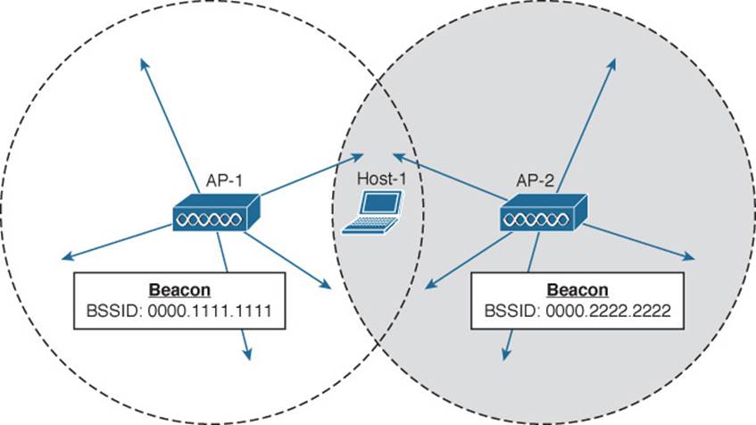
Figure 6-9 Using a Passive Scan to Discover BSSs
![]() Active scan—The device must take an active role and broadcast a probe request frame to ask any APs within range to identify themselves. The device can include a specific SSID name in the request. Any APs that receive the probe request must send a unicast probe response frame back to the device.
Active scan—The device must take an active role and broadcast a probe request frame to ask any APs within range to identify themselves. The device can include a specific SSID name in the request. Any APs that receive the probe request must send a unicast probe response frame back to the device.
In Figure 6-10, a device broadcasts a probe request to look for any APs that can offer the “guest” SSID. Both AP-1 and AP-2 receive the request and send probe responses containing their BSSIDs and other information about the BSS and SSID.
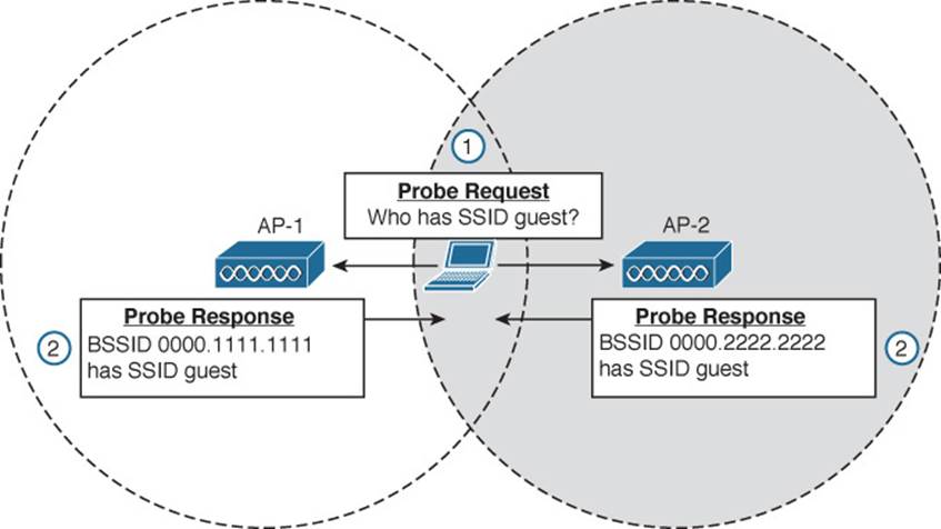
Figure 6-10 Using an Active Scan to Discover BSSs
A Client Joins a BSS
Suppose a wireless device is not currently joined to a wireless network. The device comes within range of two different APs that form a single ESS and offer a common SSID. The device performs an active scan and discovers the two APs. Through some algorithm, it decides that AP-1 is more preferable than AP-2. Figure 6-11 shows the steps that the device takes to join the network offered by AP-1.
![]()
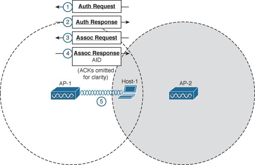
Figure 6-11 Wireless Client Joining a BSS
Step 1. Host-1 sends an authentication request frame to AP-1’s BSSID address.
Step 2. If AP-1 is satisfied with the host’s identity, it sends an authentication response frame back to Host-1.
Step 3. Now that Host-1 is known to the AP, it must ask for BSS membership by sending an association request frame to AP-1. Host-1 includes a list of its 802.11 capabilities, the SSID it wants to join, a list of data rates and channels it supports, and any parameters that are needed to secure the wireless link to the AP.
Step 4. If the AP is satisfied with the request, it sends an association response frame back to Host-1.
Step 5. The response also contains the AID that uniquely identifies Host-1 as an associated client. In effect, the AID is Host-1’s membership card while it remains a part of the BSS.
A Client Leaves a BSS
Once a wireless device successfully becomes a client of a BSS, it keeps that relationship with the AP until something happens to remove it. For example, a wireless client might be removed if it violates a security policy, is recognized as a rogue device, has a session that stays idle for too long, and so on.
A client can be removed from a BSS if the AP sends it a disassociation or a deauthentication frame. If a client is disassociated, it loses only its associated status but is still authenticated. To rejoin the BSS, the client can simply reassociate. Deauthentication is a bit more drastic. Once that happens, the device must start the whole authentication and association process over again. In Figure 6-12, Client-A has been forced to leave the BSS through either disassociation or deauthentication.
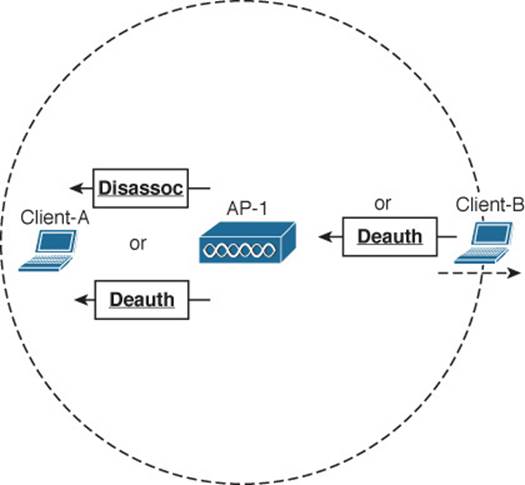
Figure 6-12 Disassociating and Deauthenticating—Two Ways to Leave a BSS
A client can gracefully remove itself from a BSS, when needed. To do this, the client simply notifies the AP by sending it a deauthentication frame. In Figure 6-12, Client-B has sent a deauthentication frame for itself to AP-1.
What happens if a client physically leaves a BSS without informing the AP? For example, suppose Client-B in Figure 6-12 reaches the edge of AP-1’s cell, but does not send a deauthentication frame? Once it goes outside the cell range, the AP might not even notice. Even before it leaves the cell, the client might just go into sleep mode and stop communicating with the AP altogether. In this case, the AP maintains the AID entry for the device, in case it returns to the cell or wakes up, but only for a certain amount of time. Cisco APs age out unresponsive clients after 5 minutes. In case the client is still listening, the AP also sends a deauthentication frame to it.
A Client Moves Between BSSs
When a wireless client is within range of several APs, it must choose to associate with only one of them. A client can join only one BSS at any given time. If the client changes its location, it might stay within its original BSS or it might move out of range and into the cell of an adjacent BSS. Moving seamlessly from one BSS to another is called roaming.
The basic roaming process is not much different than finding and associating with a BSS, except that the client does this while it is actively associated with another BSS. To switch BSSs seamlessly, the client must recognize that it is nearing the cell boundary and that it needs to find other potential cells to move into before losing the signal completely.
Figure 6-13 illustrates the basic steps of the roaming process.
![]()
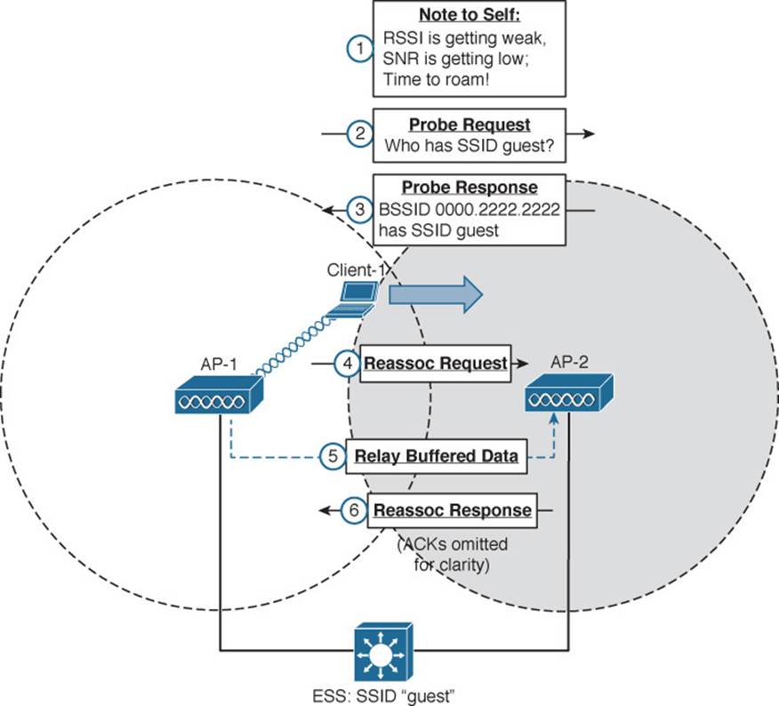
Figure 6-13 Roaming Between Two BSSs
The wireless client begins with an active association with AP-1 using SSID “guest”:
Step 1. Client-1 notices that the signal from AP-1 is degrading. Based on various conditions like the received signal strength indicator (RSSI) and SNR, the client will decide that it needs to roam.
Step 2. Client-1 begins to search for a successor BSS to move into. It broadcasts a probe request frame to look for nearby APs that can offer the same “guest” SSID.
Step 3. AP-2 receives the probe request and returns a probe response, advertising its BSSID and the “guest” SSID. Other APs may also hear the request and send probe responses of their own.
Step 4. Client-1 must decide which AP is the best candidate out of all probe responses that are received. It then sends a reassociation request frame to the new AP, asking to transfer its ESS membership from AP-1’s BSS to AP-2.
Step 5. AP-2 communicates with AP-1 over the wired DS network to begin the client handoff. Client-1’s association will be moved from AP-1 to AP-2. Any frames that are destined for the client during the handoff will be buffered on AP-1, then relayed to AP-2 and transmitted to the client.
Step 6. If the reassociation is accepted, AP-2 will inform the client with a reassociation response frame.
A Client Saves Power
Wireless devices are commonly small in size and powered by batteries. Because the devices are mobile and carried around, it is not very practical to stop and charge the batteries. To maximize the battery life, the device should conserve as much power as possible.
By default, the radio (both transmitter and receiver) is powered on all the time, so that the device is always ready to send and receive data. That might be good for performance, but applies a constant drain on the battery. Fortunately, the 802.11 standard defines some methods to save power by putting the radio to sleep when it is not needed.
Tip
Be aware that a device’s radio sleeping is different than the whole device sleeping, as when you close the lid on a laptop. While a radio is sleeping, its transmitter and receiver are powered down for a short amount of time and cannot send or receive wireless frames. In contrast, when a laptop is sleeping, most of its functions are paused for a long period of time. While asleep, a laptop can become disassociated from the AP; when it wakes, it must probe and associate again. The “legacy” method was defined in the original 802.11 standard and is described by Figure 6-14 and the following sequence of steps. (For simplicity, the ACK frames that acknowledge each frame have been omitted.)
![]()
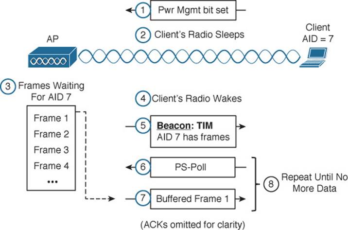
Figure 6-14 Using the Legacy Power Save Delivery Method
In a nutshell, the method works by letting the client’s radio power down and go to sleep while the AP stores up any frames that are destined for the client. The client’s radio must periodically wake up and fetch any buffered frames from the AP:
Step 1. The client informs the AP that it is entering power save mode by setting the Power Management bit in the Frame Control field of the frame header (refer to Figure 6-3).
Step 2. The client shifts its wireless radio into a very low power or “sleep” mode.
Step 3. The AP begins to buffer any unicast frames that are destined for the client while it is in power save mode.
Step 4. To check for any potentially buffered frames, the client’s radio must wake up in time to receive a beacon frame.
Step 5. The beacon can contain a traffic indication map (TIM), or a list of AID entries for clients that have buffered frames. The client, known as AID 7, has frames available and is listed in the TIM.
Step 6. The client can begin to retrieve its buffered frames one by one. To do so, it must send a PS-Poll management frame to the AP.
Step 7. The AP sends the next buffered frame to the client, along with a flag that indicates more buffered frames are available.
Step 8. The client and AP continue the exchange in Steps 6 and 7 until no more frames are available in the buffer.
Broadcast and multicast frames become special cases for clients that have radios in power save mode. Such frames are not destined for any specific client; rather, they are destined for mass delivery. Sleeping radios will miss the frames unless the AP somehow intervenes.
An AP can also buffer broadcast and multicast frames and deliver them at regular intervals. The delivery traffic indication message (DTIM) is a beacon that is sent at some multiple of regular beacon periods. The DTIM period is advertised in every beacon so that all clients know to wake up their radios in time to receive the next DTIM. At that time, the DTIM is sent, followed by any buffered broadcast and multicast frames.
The legacy TIM and DTIM schemes have one drawback—they are AP-centric. Even though a client needs to conserve its battery power, it is the AP that dictates when and how often the client’s radio should wake up and consume more power.
Ideally, a client should have more control over its own power consumption. The 802.11e amendment, certified by the Wi-Fi Alliance and known as Wi-Fi Multimedia (WMM), introduced a new quality-of-service (QoS) mechanism along with a new and improved power save mode that is more client-centric.
Traffic to and from a wireless client can be handled according to four different categories, in order of decreasing time-critical delivery: voice, video, best effort, and background. While a client is in a power save mode, the AP buffers its frames in four queues that correspond to the QoS categories. When the client is ready to wake its radio up, it sends a frame marked for one of the queues. The AP responds by sending the buffered frames in that queue to the client in a burst.
This method is known as unscheduled automatic power save delivery (U-APSD), and must be supported on both the client and the AP. The client does not have to request each frame, and the client does not have to wake its radio up until it is ready to do so. Figure 6-15 illustrates the sequence of steps involved in U-APSD, which are detailed in the list that follows.
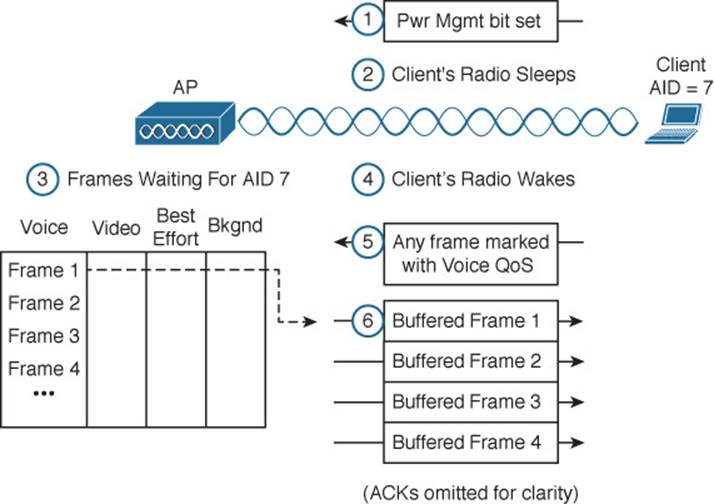
Figure 6-15 Using the U-APSD Power Save Delivery Method
Step 1. The client informs the AP that it is entering power save mode by setting the Power Management bit in a frame.
Step 2. The client puts its radio into power down or sleep mode.
Step 3. The AP buffers any frames destined for the client in the appropriate QoS queues.
Step 4. The client decides to wake its radio.
Step 5. The client is ready to receive any buffered frames from the “voice” queue, so it marks a frame as voice and signals the AP that it is awake.
Step 6. The AP sends the frames it has buffered in the voice queue in a burst.
Exam Preparation Tasks
As mentioned in the section, “How to Use This Book,” in the Introduction, you have a couple of choices for exam preparation: the exercises here, Chapter 21, “Final Review,” and the exam simulation questions on the DVD.
Review All Key Topics
Review the most important topics in this chapter, noted with the Key Topic icon in the outer margin of the page. Table 6-3 lists a reference of these key topics and the page numbers on which each is found.
![]()
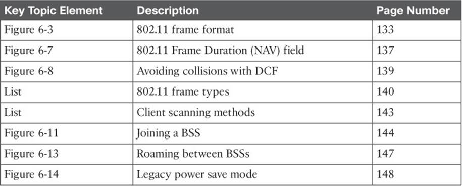
Table 6-3 Key Topics for Chapter 6
Define Key Terms
Define the following key terms from this chapter and check your answers in the glossary:
active scanning
association
backoff timer
BSS basic rate
clear channel assessment (CCA)
collision avoidance
contention window
delivery traffic indication message (DTIM)
distributed coordination function (DCF)
interframe space
network allocation vector (NAV)
open system authentication
passive scanning
physical carrier sense
reassociation
shared key authentication
traffic indication map (TIM)
unscheduled automatic power save delivery (U-APSD)
virtual carrier sense
Wireless Multimedia (WMM)
All materials on the site are licensed Creative Commons Attribution-Sharealike 3.0 Unported CC BY-SA 3.0 & GNU Free Documentation License (GFDL)
If you are the copyright holder of any material contained on our site and intend to remove it, please contact our site administrator for approval.
© 2016-2026 All site design rights belong to S.Y.A.