CCNP Routing and Switching SWITCH 300-115 Official Cert Guide (2015)
Part III. Working with Redundant Links
Chapter 9. Advanced Spanning Tree Protocol
This chapter covers the following topics that you need to master for the CCNP SWITCH exam:
![]() Rapid Spanning Tree Protocol: This section discusses the enhancements that allow switches to run STP efficiently, offering fast convergence.
Rapid Spanning Tree Protocol: This section discusses the enhancements that allow switches to run STP efficiently, offering fast convergence.
![]() Multiple Spanning Tree Protocol: This section discusses the latest IEEE standard that supports a reduced number of STP instances for a campus network while using RSTP for efficient operation.
Multiple Spanning Tree Protocol: This section discusses the latest IEEE standard that supports a reduced number of STP instances for a campus network while using RSTP for efficient operation.
Familiarity with the IEEE 802.1D STP standard is essential because that protocol is used universally to maintain loop-free bridged and switched networks. However, it now is considered a legacy protocol, offering topology change and convergence times that are not as acceptable as they once were.
This chapter discusses the many STP enhancements that are available in new standards. Rapid STP (RSTP) is presented first because it provides the foundation for efficient STP activity. RSTP can be coupled with either per-VLAN STP (PVST+) or Multiple STP modes. This allows a Layer 2 campus network to undergo change quickly and efficiently, with little downtime for today’s applications.
This chapter also covers Multiple STP (MST or MSTP). MST allows VLANs to be individually mapped into arbitrary STP instances while RSTP operates in the background. You can use MST to greatly simplify the Layer 2 topologies and STP operations when many VLANs (and many instances of STP) are present in a network.
“Do I Know This Already?” Quiz
The “Do I Know This Already?” quiz allows you to assess whether you should read this entire chapter thoroughly or jump to the “Exam Preparation Tasks” section. If you are in doubt based on your answers to these questions or your own assessment of your knowledge of the topics, read the entire chapter. Table 9-1 outlines the major headings in this chapter and the “Do I Know This Already?” quiz questions that go with them. You can find the answers in Appendix A, “Answers to the ‘Do I Know This Already?’ Quizzes.”
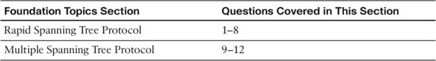
Table 9-1 “Do I Know This Already?” Foundation Topics Section-to-Question Mapping
1. Which one of the following commands enables the use of RSTP?
a. spanning-tree mode rapid-pvst
b. no spanning-tree mode pvst
c. spanning-tree rstp
d. spanning-tree mode rstp
e. None. RSTP is enabled by default.
2. On which standard is RSTP based?
a. 802.1Q
b. 802.1D
c. 802.1w
d. 802.1s
3. Which of the following is not a port state in RSTP?
a. Listening
b. Learning
c. Discarding
d. Forwarding
4. When a switch running RSTP receives an 802.1D BPDU, what happens?
a. The BPDU is discarded or dropped.
b. An ICMP message is returned.
c. The switch begins to use 802.1D rules on that port.
d. The switch disables RSTP.
5. When does an RSTP switch consider a neighbor to be down?
a. After three BPDUs are missed
b. After six BPDUs are missed
c. After the Max Age timer expires
d. After the Forward timer expires
6. Which process is used during RSTP convergence?
a. BPDU propagation
b. Synchronization
c. Forward timer expiration
d. BPDU
7. What causes RSTP to view a port as a point-to-point port?
a. Port speed
b. Port media
c. Port duplex
d. Port priority
8. Which of the following events triggers a topology change with RSTP on a nonedge port?
a. A port comes up or goes down.
b. A port comes up.
c. A port goes down.
d. A port moves to the Forwarding state.
9. Which of the following is not a characteristic of MST?
a. A reduced number of STP instances
b. Fast STP convergence
c. Eliminated need for CST
d. Interoperability with PVST+
10. Which of the following standards defines the MST protocol?
a. 802.1Q
b. 802.1D
c. 802.1w
d. 802.1s
11. How many instances of STP are supported in the Cisco implementation of MST?
a. 1
b. 16
c. 256
d. 4096
12. What switch command can be used to change from PVST+ to MST?
a. spanning-tree mst enable
b. no spanning-tree pvst+
c. spanning-tree mode mst
d. spanning-tree mst
Foundation Topics
Rapid Spanning Tree Protocol
The IEEE 802.1D Spanning Tree Protocol was designed to keep a switched or bridged network loop free, with adjustments made to the network topology dynamically. A topology change typically takes 30 seconds, with a port moving from the Blocking state to the Forwarding state after two intervals of the Forward Delay timer. As technology has improved, 30 seconds has become an unbearable length of time to wait for a production network to fail over or “heal” itself during a problem.
The IEEE 802.1w standard was developed to use 802.1D’s principal concepts and make the resulting convergence much faster. This is also known as the Rapid Spanning Tree Protocol (RSTP), which defines how switches must interact with each other to keep the network topology loop free in a very efficient manner.
As with 802.1D, RSTP’s basic functionality can be applied as a single instance or multiple instances. This can be done by using RSTP as the underlying mechanism for the Cisco-proprietary Per-VLAN Spanning Tree Protocol (PVST+). The resulting combination is called Rapid PVST+(RPVST+). RSTP also is used as part of the IEEE 802.1s Multiple Spanning Tree (MST) operation. RSTP operates consistently in each, but replicating RSTP as multiple instances requires different approaches.
RSTP Port Behavior
In 802.1D, each switch port is assigned a role and a state at any given time. Depending on the port’s proximity to the root bridge, it takes on one of the following roles:
![]() Root port
Root port
![]() Designated port
Designated port
![]() Blocking port (neither root nor designated)
Blocking port (neither root nor designated)
The Cisco proprietary UplinkFast feature also reserved a hidden alternate port role for ports that offered parallel paths to the root but were in the Blocking state.
Recall that each switch port also is assigned one of five possible states:
![]() Disabled
Disabled
![]() Blocking
Blocking
![]() Listening
Listening
![]() Learning
Learning
![]() Forwarding
Forwarding
Only the Forwarding state allows data to be sent and received. A port’s state is somewhat tied to its role. For example, a blocking port cannot be a root port or a designated port.
RSTP achieves its rapid nature by letting each switch interact with its neighbors through each port. This interaction is performed based on a port’s role, not strictly on the bridge protocol data units (BPDUs) that are relayed from the root bridge. After the role is determined, each port can be given a state that determines what it does with incoming data.

The root bridge in a network using RSTP is elected just as with 802.1D—by the lowest bridge ID. After all switches agree on the identity of the root, the following port roles are determined:
![]() Root port: The one switch port on each switch that has the best root path cost to the root. This is identical to 802.1D. (By definition, the root bridge has no root ports.)
Root port: The one switch port on each switch that has the best root path cost to the root. This is identical to 802.1D. (By definition, the root bridge has no root ports.)
![]() Designated port: The switch port on a network segment that has the best root path cost to the root.
Designated port: The switch port on a network segment that has the best root path cost to the root.
![]() Alternate port: A port that has an alternative path to the root, different from the path the root port takes. This path is less desirable than that of the root port. (An example of this is an access layer switch with two uplink ports; one becomes the root port, and the other is an alternate port.)
Alternate port: A port that has an alternative path to the root, different from the path the root port takes. This path is less desirable than that of the root port. (An example of this is an access layer switch with two uplink ports; one becomes the root port, and the other is an alternate port.)
![]() Backup port: A port that provides a redundant (but less desirable) connection to a segment where another switch port already connects. If that common segment is lost, the switch might or might not have a path back to the root.
Backup port: A port that provides a redundant (but less desirable) connection to a segment where another switch port already connects. If that common segment is lost, the switch might or might not have a path back to the root.
RSTP defines port states only according to what the port does with incoming frames. (Naturally, if incoming frames are ignored or dropped, so are outgoing frames.) Any port role can have any of these port states:
![]() Discarding: Incoming frames simply are dropped; no MAC addresses are learned. (This state combines the 802.1D Disabled, Blocking, and Listening states because all three did not effectively forward anything. The Listening state is not needed because RSTP quickly can negotiate a state change without listening for BPDUs first.)
Discarding: Incoming frames simply are dropped; no MAC addresses are learned. (This state combines the 802.1D Disabled, Blocking, and Listening states because all three did not effectively forward anything. The Listening state is not needed because RSTP quickly can negotiate a state change without listening for BPDUs first.)
![]() Learning: Incoming frames are dropped, but MAC addresses are learned.
Learning: Incoming frames are dropped, but MAC addresses are learned.
![]() Forwarding: Incoming frames are forwarded according to MAC addresses that have been (and are being) learned.
Forwarding: Incoming frames are forwarded according to MAC addresses that have been (and are being) learned.
BPDUs in RSTP
In 802.1D, BPDUs basically originate from the root bridge and are relayed by all switches down through the tree. Because of this propagation of BPDUs, 802.1D convergence must wait for steady-state conditions before proceeding.
RSTP uses the 802.1D BPDU format for backward compatibility. However, some previously unused bits in the Message Type field are used. The sending switch port identifies itself by its RSTP role and state. The BPDU version also is set to 2 to distinguish RSTP BPDUs from 802.1D BPDUs. In addition, RSTP uses an interactive process so that two neighboring switches can negotiate state changes. Some BPDU bits are used to flag messages during this negotiation.
BPDUs are sent out every switch port at hello time intervals, regardless of whether BPDUs are received from the root. In this way, any switch anywhere in the network can play an active role in maintaining the topology. Switches also can expect to receive regular BPDUs from their neighbors. When three BPDUs are missed in a row, that neighbor is presumed to be down, and all information related to the port leading to the neighbor immediately is aged out. This means that a switch can detect a neighbor failure in three Hello intervals (default 6 seconds), versus the Max Age timer interval (default 20 seconds) for 802.1D.
Because RSTP distinguishes its BPDUs from 802.1D BPDUs, it can coexist with switches still using 802.1D. Each port attempts to operate according to the STP BPDU that is received. For example, when an 802.1D BPDU (Version 0) is received on a port, that port begins to operate according to the 802.1D rules.
However, each port has a measure that locks the protocol in use, in case BPDUs from both 802.1D and RSTP are received within a short time frame. This can occur if the switches in a network are being migrated from one STP type to another. Instead of flapping or toggling the STP type during a migration, the switch holds the protocol type for the duration of a migration delay timer. After this timer expires, the port is free to change protocols if needed.
RSTP Convergence
The convergence of STP in a network is the process that takes all switches from a state of independence (each thinks it must be the STP root) to one of uniformity, in which each switch has a place in a loop-free tree topology. You can think of convergence as a two-stage process:
1. One common root bridge must be “elected,” and all switches must know about it.
2. The state of every switch port in the STP domain must be brought from a Blocking state to the appropriate state to prevent loops.
Convergence generally takes time because messages are propagated from switch to switch. The traditional 802.1D STP also requires the expiration of several timers before switch ports can safely be allowed to forward data.
RSTP takes a different approach when a switch needs to decide how to participate in the tree topology. When a switch first joins the topology (perhaps it was just powered up) or has detected a failure in the existing topology, RSTP requires it to base its forwarding decisions on the type of port.
Port Types
Every switch port can be considered one of the following types:
![]() Edge port: A port at the “edge” of the network, where only a single host connects. Traditionally, this has been identified by enabling the STP PortFast feature. RSTP keeps the PortFast concept for familiarity. By definition, the port cannot form a loop as it connects to one host, so it can be placed immediately in the Forwarding state. However, if a BPDU ever is received on an edge port, the port immediately loses its edge port status.
Edge port: A port at the “edge” of the network, where only a single host connects. Traditionally, this has been identified by enabling the STP PortFast feature. RSTP keeps the PortFast concept for familiarity. By definition, the port cannot form a loop as it connects to one host, so it can be placed immediately in the Forwarding state. However, if a BPDU ever is received on an edge port, the port immediately loses its edge port status.
![]() Root port: The port that has the best cost to the root of the STP instance. Only one root port can be selected and active at any time, although alternative paths to the root can exist through other ports. If alternative paths are detected, those ports are identified as alternative root ports and immediately can be placed in the Forwarding state when the existing root port fails.
Root port: The port that has the best cost to the root of the STP instance. Only one root port can be selected and active at any time, although alternative paths to the root can exist through other ports. If alternative paths are detected, those ports are identified as alternative root ports and immediately can be placed in the Forwarding state when the existing root port fails.
![]() Point-to-point port: Any port that connects to another switch and becomes a designated port. A quick handshake with the neighboring switch, rather than a timer expiration, decides the port state. BPDUs are exchanged back and forth in the form of a proposal and an agreement. One switch proposes that its port becomes a designated port; if the other switch agrees, it replies with an agreement message.
Point-to-point port: Any port that connects to another switch and becomes a designated port. A quick handshake with the neighboring switch, rather than a timer expiration, decides the port state. BPDUs are exchanged back and forth in the form of a proposal and an agreement. One switch proposes that its port becomes a designated port; if the other switch agrees, it replies with an agreement message.
Point-to-point ports automatically are determined by the duplex mode in use. Full-duplex ports are considered point to point because only two switches can be present on the link. STP convergence can occur quickly over a point-to-point link through RSTP handshake messages.
Half-duplex ports, on the other hand, are considered to be on a shared medium with possibly more than two switches present. They are not point-to-point ports. STP convergence on a half-duplex port must occur between several directly connected switches. Therefore, the traditional 802.1D style convergence must be used. This results in a slower response because the shared-medium ports must go through the fixed Listening and Learning state time periods.
It is easy to see how two switches quickly can converge to a common idea of which one is the root and which one will have the designated port after just a single exchange of BPDUs. What about a larger network, where 802.1D BPDUs normally would have to be relayed from switch to switch?
RSTP handles the complete STP convergence of the network as a propagation of handshakes over point-to-point links. When a switch needs to make an STP decision, a handshake is made with the nearest neighbor. When that is successful, the handshake sequence is moved to the next switch and the next, as an ever-expanding wave moving toward the network’s edges.
During each handshake sequence, a switch must take measures to completely ensure that it will not introduce a bridging loop before moving the handshake outward. This is done through a synchronization process.
Synchronization
To participate in RSTP convergence, a switch must decide the state of each of its ports. Nonedge ports begin in the Discarding state. After BPDUs are exchanged between the switch and its neighbor, the Root Bridge can be identified. If a port receives a superior BPDU from a neighbor, that port becomes the root port.
For each nonedge port, the switch exchanges a proposal-agreement handshake to decide the state of each end of the link. Each switch assumes that its port should become the designated port for the segment, and a proposal message (a configuration BPDU) is sent to the neighbor suggesting this.
When a switch receives a proposal message on a port, the following sequence of events occurs. Figure 9-1 shows the sequence, based on the center Catalyst switch:
1. If the proposal’s sender has a superior BPDU, the local switch realizes that the sender should be the designated switch (having the designated port) and that its own port must become the new root port.
2. Before the switch agrees to anything, it must synchronize itself with the topology.
3. All nonedge ports immediately are moved into the Discarding (blocking) state so that no bridging loops can form.
4. An agreement message (a configuration BPDU) is sent back to the sender, indicating that the switch is in agreement with the new designated port choice. This also tells the sender that the switch is in the process of synchronizing itself.
5. The root port immediately is moved to the Forwarding state. The sender’s port also immediately can begin forwarding.
6. For each nonedge port that is currently in the Discarding state, a proposal message is sent to the respective neighbor.
7. An agreement message is expected and received from a neighbor on a nonedge port.
8. The nonedge port immediately is moved to the Forwarding state.
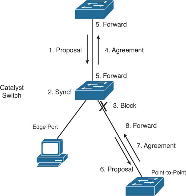
Figure 9-1 Sequence of Events During RSTP Convergence
Notice that the RSTP convergence begins with a switch sending a proposal message. The recipient of the proposal must synchronize itself by effectively isolating itself from the rest of the topology. All nonedge ports are blocked until a proposal message can be sent, causing the nearest neighbors to synchronize themselves. This creates a moving “wave” of synchronizing switches, which quickly can decide to start forwarding on their links only if their neighbors agree. Figure 9-2 shows how the synchronization wave travels through a network at three successive time intervals. Isolating the switches along the traveling wave inherently prevents bridging loops.
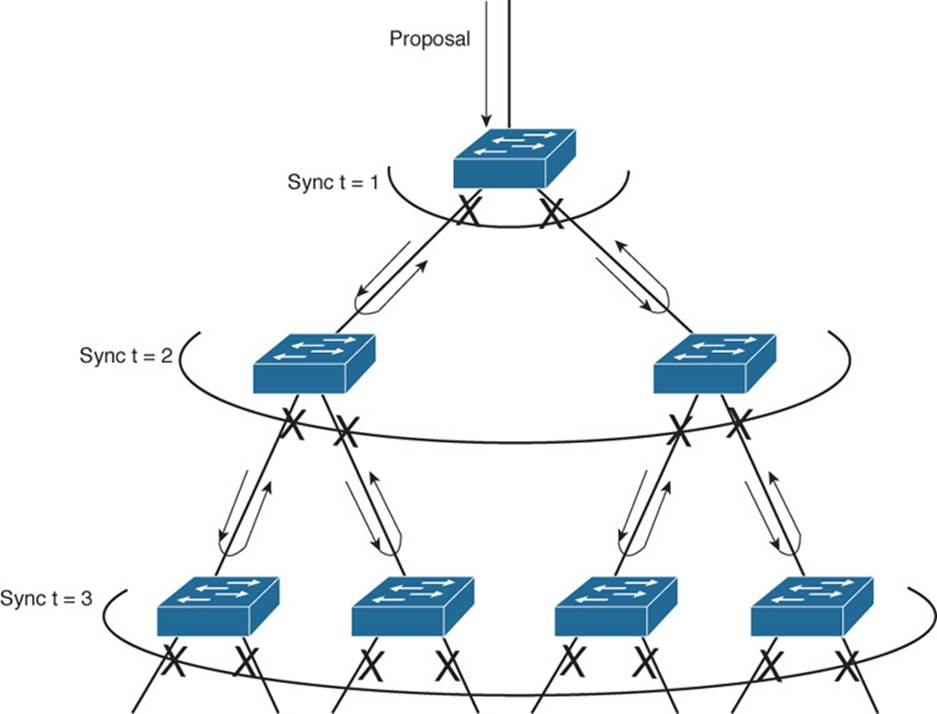
Figure 9-2 RSTP Synchronization Traveling Through a Network
The entire convergence process happens quickly, at the speed of BPDU transmission, without the use of any timers. However, a designated port that sends a proposal message might not receive an agreement message reply. Suppose that the neighboring switch does not understand RSTP or has a problem replying. The sending switch then must become overly cautious and must begin playing by the 802.1D rules: The port must be moved through the legacy Listening and Learning states (using the Forward Delay timer) before moving to the Forwarding state.
Topology Changes and RSTP
Recall that when an 802.1D switch detects a port state change (either up or down), it signals the root bridge by sending Topology Change Notification (TCN) BPDUs. The root bridge, in turn, must signal the topology change by sending out a TCN message that is relayed to all switches in the STP domain.
RSTP detects a topology change only when a nonedge port transitions to the Forwarding state. This might seem odd because a link failure is not used as a trigger. RSTP uses all its rapid convergence mechanisms to prevent bridging loops from forming. Therefore, topology changes are detected only so that bridging tables can be updated and corrected as hosts appear first on a failed port and then on a different functioning port.
When a topology change is detected, a switch must propagate news of the change to other switches in the network so that they can correct their bridging tables, too. This process is similar to the convergence and synchronization mechanism; topology change (TC) messages propagate through the network in an ever-expanding wave.
BPDUs, with their TC bit set, are sent out all the nonedge designated ports. This is done until the TC timer expires, after two intervals of the Hello time. This notifies neighboring switches of the new link and the topology change. In addition, all MAC addresses associated with the nonedge designated ports are flushed from the content-addressable memory (CAM) table. This forces the addresses to be relearned after the change, in case hosts now appear on a different link.
All neighboring switches that receive the TC messages also must flush the MAC addresses learned on all ports except the one that received the TC message. Those switches then must send TC messages out their nonedge designated ports, and so on.
RSTP Configuration
By default, a switch operates in Per-VLAN Spanning Tree Plus (PVST+) mode using traditional 802.1D STP. Therefore, RSTP cannot be used until a different spanning-tree mode (MST or RPVST+) is enabled. Remember that RSTP is just the underlying mechanism that a spanning-tree mode can use to detect topology changes and converge a network into a loop-free topology.
The only configuration changes related to RSTP affect the port or link type. The link type is used to determine how a switch negotiates topology information with its neighbors.
To configure a port as an RSTP edge port, use the following interface configuration command:
Switch(config-if)# spanning-tree portfast
You already should be familiar with this command from the 802.1D STP configuration. After PortFast is enabled, the port is considered to have only one host and is positioned at the edge of the network.
By default, RSTP automatically decides that a port is a point-to-point link if it is operating in full-duplex mode. Ports connecting to other switches are usually full duplex because there are only two switches on the link. However, you can override the automatic determination, if needed. For example, a port connecting to one other switch might be operating at half duplex, for some reason. To force the port to act as a point-to-point link, use the following interface configuration command:
Switch(config-if)# spanning-tree link-type point-to-point
Rapid Per-VLAN Spanning Tree Protocol
Chapter 6, “Traditional Spanning Tree Protocol,” describes PVST+ as the default STP mode on Catalyst switches. In PVST+, one spanning tree instance is created and used for each active VLAN that is defined on the switch. Each STP instance behaves according to the traditional 802.1D STP rules.
You can improve the efficiency of each STP instance by configuring a switch to begin using RSTP instead. This means that each VLAN will have its own independent instance of RSTP running on the switch. This mode is known as Rapid PVST+ (RPVST+).
You need only one configuration step to change the STP mode and begin using RPVST+. You can use the following global configuration command to accomplish this:
Switch(config)# spanning-tree mode rapid-pvst
Be careful when you use this command on a production network because any STP process that is currently running must be restarted. This can cause functioning links to move through the traditional STP states, preventing data from flowing for a short time.
Tip
To revert back to the default PVST+ mode, using traditional 802.1D STP, you can use the following command:
Switch(config)# spanning-tree mode pvst
After you enable the RPVST+ mode, the switch must begin supporting both RSTP and 802.1D STP neighbors. The switch can detect the neighbor’s STP type by the BPDU version that is received. You can see the neighbor type in the output of the show spanning-tree vlan vlan-id command, as demonstrated in Example 9-1.
Example 9-1 Detecting a Neighboring Switch’s STP Type
Switch# show spanning-tree vlan 171
VLAN0171
Spanning tree enabled protocol rstp
Root ID Priority 4267
Address 00d0.0457.38aa
Cost 3
Port 833 (Port-channel1)
Hello Time 2 sec Max Age 20 sec Forward Delay 15 sec
Bridge ID Priority 32939 (priority 32768 sys-id-ext 171)
Address 0007.0d55.a800
Hello Time 2 sec Max Age 20 sec Forward Delay 15 sec
Aging Time 300
Interface Role Sts Cost Prio.Nbr Type
---------------- ---- ---- --------- -------- -------------------------------
Gi1/0/7 Desg FWD 4 128.7 P2p
Gi1/0/9/6 Altn BLK 4 128.9 P2p Peer(STP)
Po1 Root FWD 3 128.104 P2p
Po2 Desg FWD 3 128.834 P2p
Po3 Desg FWD 3 128.835 P2p
Switch#
The output in Example 9-1 shows information about the RSTP instance for VLAN 171. The first shaded line confirms that the local switch indeed is running RSTP. (The only other way to confirm the STP mode is to locate the spanning-tree mode command in the running configuration.)
In addition, this output displays all the active ports participating in the VLAN 171 instance of RSTP, along with their port types. The string P2p denotes a point-to-point RSTP port type in which a full-duplex link connects two neighboring switches that both are running RSTP. If you see P2p Peer(STP), the port is a point-to-point type but the neighboring device is running traditional 802.1D STP.
Multiple Spanning Tree Protocol
Chapter 6 covered two “flavors” of spanning-tree implementations, IEEE 802.1Q and PVST+, both based on the 802.1D STP. These also represent the two extremes of STP operation in a network:
![]() 802.1Q: Only a single instance of STP is used for all VLANs. If there are 500 VLANs, only 1 instance of STP will be running. This is called the Common Spanning Tree (CST) and operates over the trunk’s native VLAN.
802.1Q: Only a single instance of STP is used for all VLANs. If there are 500 VLANs, only 1 instance of STP will be running. This is called the Common Spanning Tree (CST) and operates over the trunk’s native VLAN.
![]() PVST+: One instance of STP is used for each active VLAN in the network. If there are 500 VLANs, 500 independent instances of STP will be running.
PVST+: One instance of STP is used for each active VLAN in the network. If there are 500 VLANs, 500 independent instances of STP will be running.
In most networks, each switch has a redundant path to another switch. For example, an access layer switch usually has two uplinks, each connecting to a different distribution or core layer switch. If 802.1Q’s CST is used, only one STP instance will run. This means that there is only one loop-free topology at any given time and that only one of the two uplinks in the access layer switch will be forwarding. The other uplink always will be blocking.
Obviously, arranging the network so that both uplinks can be used simultaneously would be best. One uplink should carry one set of VLANs, whereas the other should carry a different set as a type of load balancing.
PVST+ seems more attractive to meet that goal because it allows different VLANs to have different topologies so that each uplink can be forwarding. But think of the consequences: As the number of VLANs increases, so does the number of independent STP instances. Each instance uses some amount of the switch CPU and memory resources. The more instances that are in use, the fewer CPU resources will be available for switching.
Beyond that, what is the real benefit of having 500 STP topologies for 500 VLANs, when only a small number of possible topologies exist for a switch with two uplinks? Figure 9-3 shows a typical network with an access layer switch connecting to a pair of core switches. Two VLANs are in use, with the root bridges configured to support load balancing across the two uplinks. The right portion of the figure shows every possible topology for VLANs A and B. Notice that because the access layer switch has only two uplinks, only two topologies actually matter—one in which the left uplink forwards, and one in which the right uplink forwards.
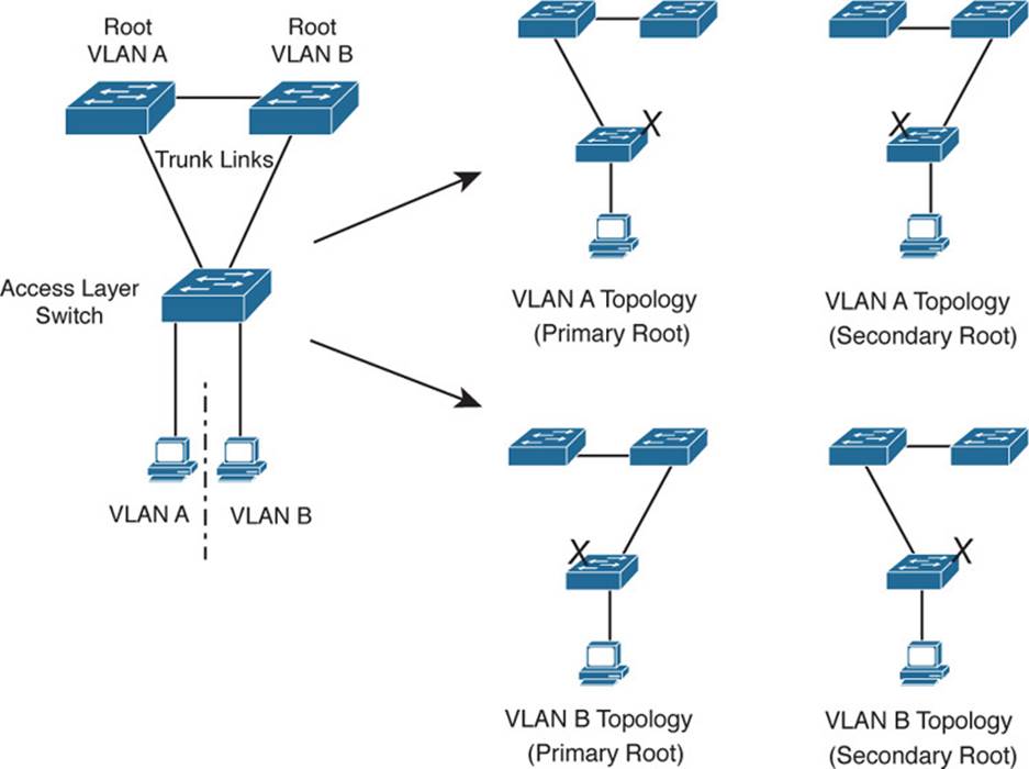
Figure 9-3 Possible STP Topologies for Two VLANs
Notice also that the number of useful topologies is independent of the number of VLANs. If 10 or 100 VLANs were used in the figure, there would still be only two possible outcomes at the access layer switch. Therefore, running 10 or 100 instances of STP when only a couple would suffice is rather wasteful.
The Multiple Spanning Tree Protocol was developed to address the lack of and surplus of STP instances. As a result, the network administrator can configure exactly the number of STP instances that makes sense for the enterprise network, no matter how many VLANs are in use. MST is defined in the IEEE 802.1s standard.
MST Overview
MST is built on the concept of mapping one or more VLANs to a single STP instance. Multiple instances of STP can be used (hence the name MST), with each instance supporting a different group of VLANs.
For the network shown in Figure 9-3, only two MST instances would be needed. Each could be tuned to result in a different topology so that Instance 1 would forward on the left uplink, whereas Instance 2 would forward on the right uplink. Therefore, VLAN A would be mapped to Instance 1, and VLAN B would be mapped to Instance 2.
To implement MST in a network, you need to determine the following:
![]() The number of STP instances needed to support the desired topologies
The number of STP instances needed to support the desired topologies
![]() Whether to map a set of VLANs to each instance
Whether to map a set of VLANs to each instance
MST Regions
MST is different from 802.1Q and PVST+, although it can interoperate with them. If a switch is configured to use MST, it somehow must figure out which of its neighbors are using which type of STP. This is done by configuring switches into common MST regions, where every switch in a region runs MST with compatible parameters.
In most networks, a single MST region is sufficient, although you can configure more than one region. Within the region, all switches must run the instance of MST that is defined by the following attributes:
![]() MST configuration name (32 characters)
MST configuration name (32 characters)
![]() MST configuration revision number (0 to 65535)
MST configuration revision number (0 to 65535)
![]() MST instance-to-VLAN mapping table (4096 entries)
MST instance-to-VLAN mapping table (4096 entries)
If two switches have the same set of attributes, they belong to the same MST region. If not, they belong to two independent regions.
MST BPDUs contain configuration attributes so that switches receiving BPDUs can compare them against their local MST configurations. If the attributes match, the STP instances within MST can be shared as part of the same region. If not, a switch is seen to be at the MST region boundary, where one region meets another or one region meets traditional 802.1D STP.
Note
The entire MST instance-to-VLAN mapping table is not sent in the BPDUs because the instance mappings must be configured on each switch. Instead, a digest, or a hash code computed from the table contents, is sent. As the contents of the table change, the digest value will be different. Therefore, a switch quickly can compare a received digest to its own to see if the advertised table is the same.
Spanning-Tree Instances Within MST
MST was designed to interoperate with all other forms of STP. Therefore, it also must support STP instances from each STP type. This is where MST can get confusing. Think of the entire enterprise network as having a single CST topology so that one instance of STP represents any and all VLANs and MST regions present. The CST maintains a common loop-free topology while integrating all forms of STP that might be in use.
To do this, CST must regard each MST region as a single “black box” bridge because it has no idea what is inside the region, nor does it care. CST maintains a loop-free topology only with the links that connect the regions to each other and to standalone switches running 802.1Q CST.
IST Instances
Something other than CST must work out a loop-free topology inside each MST region. Within a single MST region, an Internal Spanning Tree (IST) instance runs to work out a loop-free topology between the links where CST meets the region boundary and all switches inside the region. Think of the IST instance as a locally significant CST, bounded by the edges of the region.
The IST presents the entire region as a single virtual bridge to the CST outside. BPDUs are exchanged at the region boundary only over the native VLAN of trunks, as if a single CST were in operation. And, indeed, it is.
Figure 9-4 shows the basic concept behind the IST instance. The network at the left has an MST region, where several switches are running compatible MST configurations. Another switch is outside the region because it is running only the CST from 802.1Q.
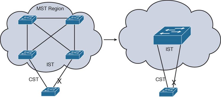
Figure 9-4 Concepts Behind the IST Instance
The same network is shown at the right, where the IST has produced a loop-free topology for the network inside the region. The IST makes the internal network look like a single bridge (the “big switch” in the cloud) that can interface with the CST running outside the region.
MST Instances
Recall that the whole idea behind MST is the capability to map multiple VLANs to a smaller number of STP instances. Inside a region, the actual MST instances (MSTI) exist alongside the IST. Cisco supports a maximum of 16 MSTIs in each region. The IST always exists as MSTI number 0, leaving MSTIs 1 through 15 available for use.
Figure 9-5 shows how different MSTIs can exist within a single MST region. The left portion of the figure is identical to that of Figure 9-4. In this network, two MST instances, MSTI 1 and MSTI 2, are configured with different VLANs mapped to each. Their topologies follow the same structure as the network on the left side of the figure, but each has converged differently.
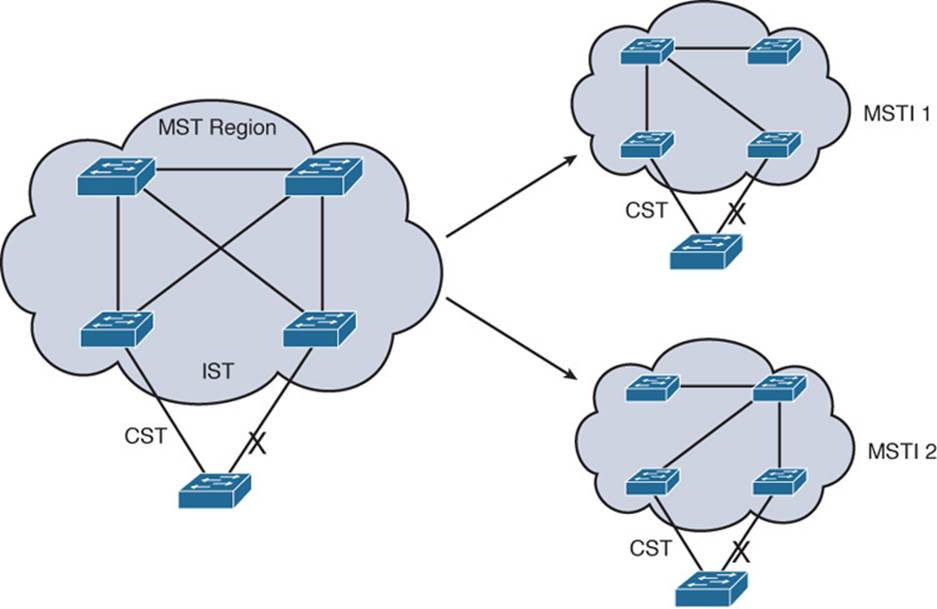
Figure 9-5 Concepts Behind MST Instances
Notice that within the MST cloud, there are now three independent STP instances coexisting: MSTI1, MSTI 2, and the IST.
Only the IST (MSTI 0) is allowed to send and receive MST BPDUs. Information about each of the other MSTIs is appended to the MST BPDU as an M-record. Therefore, even if a region has all 16 instances active, only 1 BPDU is needed to convey STP information about them all.
Each of the MSTIs is significant only within a region, even if an adjacent region has the same MSTIs in use. In other words, the MSTIs combine with the IST only at the region boundary to form a subtree of the CST. That means only IST BPDUs are sent into and out of a region.
What if an MST region connects with a switch running traditional PVST+? MST can detect this situation by listening to the received BPDUs. If BPDUs are heard from more than one VLAN (the CST), PVST+ must be in use. When the MST region sends a BPDU toward the PVST+ switch, the IST BPDUs are replicated into all the VLANs on the PVST+ switch trunk.
Tip
Keep in mind that the IST instance is active on every port on a switch. Even if a port does not carry VLANs that have been mapped to the IST, IST must be running on the port.
Also, by default, all VLANs are mapped to the IST instance. You must explicitly map them to other instances, if needed.
MST Configuration
You must manually configure the MST configuration attributes on each switch in a region. There is currently no method to propagate this information from one switch to another, as is done with a protocol such as VLAN Trunking Protocol (VTP). To define the MST region, use the following configuration commands in the order shown:
Step 1. Enable MST on the switch:
Switch(config)# spanning-tree mode mst
Step 2. Enter the MST configuration mode:
Switch(config)# spanning-tree mst configuration
Step 3. Assign a region configuration name (up to 32 characters):
Switch(config-mst)# name name
Step 4. Assign a region configuration revision number (0 to 65,535):
Switch(config-mst)# revision version
The configuration revision number gives you a means of tracking changes to the MST region configuration. Each time you make changes to the configuration, you should increase the number by one. Remember that the region configuration (including the revision number) must match on all switches in the region. Therefore, you also need to update the revision numbers on the other switches to match.
Step 5. Map VLANs to an MST instance:
Switch(config-mst)# instance instance-id vlan vlan-list
The instance-id (0 to 15) carries topology information for the VLANs listed in vlan-list. The list can contain one or more VLANs separated by commas. You also can add a range of VLANs to the list by separating numbers with a hyphen. VLAN numbers can range from 1 to 4094. (Remember that, by default, all VLANs are mapped to instance 0, the IST.)
Step 6. Show the pending changes you have made:
Switch(config-mst)# show pending
Step 7. Exit the MST configuration mode; commit the changes to the active MST region configuration:
Switch(config-mst)# exit
After MST is enabled and configured, PVST+ operation stops and the switch changes to RSTP operation. A switch cannot run both MST and PVST+ at the same time.
You also can tune the parameters that MST uses when it interacts with CST or traditional 802.1D. The parameters and timers are identical to those discussed in Chapter 7, “Spanning-Tree Configuration.” In fact, the commands are very similar except for the addition of the mst keyword and the instance-id. Instead of tuning STP for a VLAN instance, you use an MST instance.
Table 9-2 summarizes the commands as a quick reference. Notice that the timer configurations are applied to MST as a whole, not to a specific MST instance. This is because all instance timers are defined through the IST instance and BPDUs.
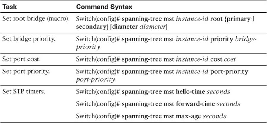
Table 9-2 MST Configuration Commands
Exam Preparation Tasks
Review All Key Topics
Review the most important topics in the chapter, noted with the Key Topic icon in the outer margin of the page. Table 9-3 lists a reference of these key topics and the page numbers on which each is found.
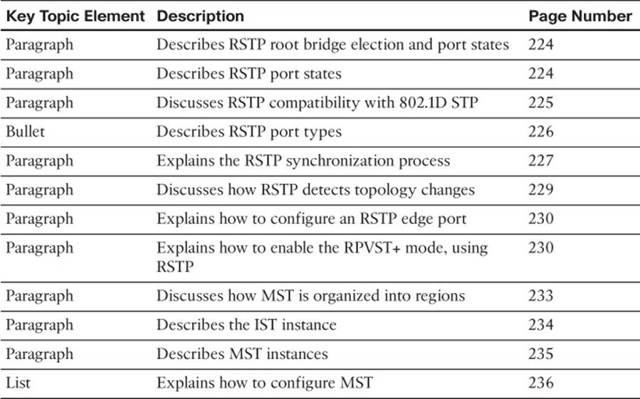
Table 9-3 Key Topics for Chapter 9
Complete Tables and Lists from Memory
Print a copy of Appendix C, “Memory Tables,” (found on the CD), or at least the section for this chapter, and complete the tables and lists from memory. Appendix D, “Memory Table Answer Key,” also on the CD, includes completed tables and lists to check your work.
Define Key Terms
Define the following key terms from this chapter, and check your answers in the glossary:
RSTP
RPVST+
alternate port
backup port
discarding state
edge port
point-to-point port
synchronization
MST
MST region
IST instance
MST instance (MSTI)
Use Command Reference to Check Your Memory
This section includes the most important configuration and EXEC commands covered in this chapter. It might not be necessary to memorize the complete syntax of every command, but you should remember the basic keywords that are needed.
To test your memory of the Rapid STP and MST commands, cover the right side of Tables 9-4 and 9-5 with a piece of paper, read the description on the left side, and then see how much of the command you can remember.
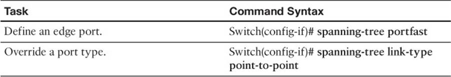
Table 9-4 RSTP Configuration Commands
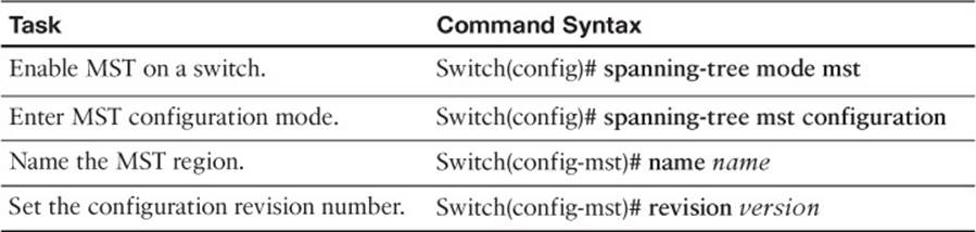
Table 9-5 MST Region Configuration Commands
All materials on the site are licensed Creative Commons Attribution-Sharealike 3.0 Unported CC BY-SA 3.0 & GNU Free Documentation License (GFDL)
If you are the copyright holder of any material contained on our site and intend to remove it, please contact our site administrator for approval.
© 2016-2026 All site design rights belong to S.Y.A.