CCNP Routing and Switching SWITCH 300-115 Official Cert Guide (2015)
Part III. Working with Redundant Links
Chapter 10. Aggregating Switch Links
This chapter covers the following topics that you need to master for the CCNP SWITCH exam:
![]() Switch Port Aggregation with EtherChannel: This section discusses the concept of aggregating, or “bundling,” physical ports into a single logical link. Methods for load balancing traffic across the physical links also are covered.
Switch Port Aggregation with EtherChannel: This section discusses the concept of aggregating, or “bundling,” physical ports into a single logical link. Methods for load balancing traffic across the physical links also are covered.
![]() EtherChannel Negotiation Protocols: This section covers two protocols that dynamically negotiate and control EtherChannels: Port Aggregation Protocol (PAgP), a Cisco proprietary protocol, and Link Aggregation Control Protocol (LACP), a standards-based protocol.
EtherChannel Negotiation Protocols: This section covers two protocols that dynamically negotiate and control EtherChannels: Port Aggregation Protocol (PAgP), a Cisco proprietary protocol, and Link Aggregation Control Protocol (LACP), a standards-based protocol.
![]() EtherChannel Configuration: This section explains the Catalyst switch commands needed to configure EtherChannel.
EtherChannel Configuration: This section explains the Catalyst switch commands needed to configure EtherChannel.
![]() Troubleshooting an EtherChannel: This section gives a brief summary of things to consider and commands to use when an aggregated link is not operating properly.
Troubleshooting an EtherChannel: This section gives a brief summary of things to consider and commands to use when an aggregated link is not operating properly.
In previous chapters, you learned about connecting switches and organizing users and devices into common workgroups. Using these principles, end users can be given effective access to resources both on and off the campus network. However, today’s mission-critical applications and services demand networks that provide high availability and reliability.
This chapter presents technologies that you can use in a campus network to provide higher bandwidth and reliability between switches.
“Do I Know This Already?” Quiz
The “Do I Know This Already?” quiz allows you to assess whether you should read this entire chapter thoroughly or jump to the “Exam Preparation Tasks” section. If you are in doubt based on your answers to these questions or your own assessment of your knowledge of the topics, read the entire chapter. Table 10-1 outlines the major headings in this chapter and the “Do I Know This Already?” quiz questions that go with them. You can find the answers in Appendix A, “Answers to the ‘Do I Know This Already?’ Quizzes.”
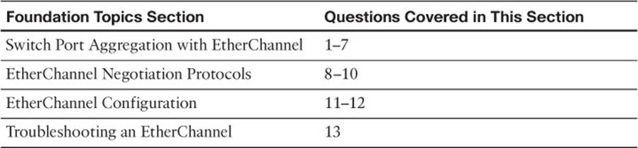
Table 10-1 “Do I Know This Already?” Foundation Topics Section-to-Question Mapping
1. If Gigabit Ethernet ports are bundled into an EtherChannel, what is the maximum throughput supported on a Catalyst switch?
a. 1 Gbps
b. 2 Gbps
c. 4 Gbps
d. 8 Gbps
e. 16 Gbps
2. Which of these methods distributes traffic over an EtherChannel?
a. Round robin
b. Least-used link
c. A function of address
d. A function of packet size
3. What type of interface represents an EtherChannel as a whole?
a. Channel
b. Port
c. Port channel
d. Channel port
4. Which of the following is not a valid method for EtherChannel load balancing?
a. Source MAC address
b. Source and destination MAC addresses
c. Source IP address
d. IP precedence
e. UDP/TCP port
5. How can the EtherChannel load-balancing method be set?
a. Per switch port
b. Per EtherChannel
c. Globally per switch
d. Cannot be configured
6. What logical operation is performed to calculate EtherChannel load balancing as a function of two addresses?
a. OR
b. AND
c. XOR
d. NOR
7. Which one of the following is a valid combination of ports for an EtherChannel?
a. Two access links (one VLAN 5, one VLAN 5)
b. Two access links (one VLAN 1, one VLAN 10)
c. Two trunk links (one VLANs 1 to 10, one VLANs 1, 11 to 20)
d. Two 10/100/1000 Ethernet links (both full duplex, one 100 Mbps)
8. Which of these is a method for negotiating an EtherChannel?
a. PAP
b. CHAP
c. LAPD
d. LACP
9. Which of the following is a valid EtherChannel negotiation mode combination between two switches?
a. PAgP auto, PAgP auto
b. PAgP auto, PAgP desirable
c. on, PAgP auto
d. LACP passive, LACP passive
10. When is PAgP’s “desirable silent” mode useful?
a. When the switch should not send PAgP frames
b. When the switch should not form an EtherChannel
c. When the switch should not expect to receive PAgP frames
d. When the switch is using LACP mode
11. Which of the following EtherChannel modes does not send or receive any negotiation frames?
a. channel-group 1 mode passive
b. channel-group 1 mode active
c. channel-group 1 mode on
d. channel-group 1 mode desirable
e. channel-group 1 mode auto
12. Two computers are the only hosts sending IP data across an EtherChannel between two switches. Several different applications are being used between them. Which of these load-balancing methods would be more likely to use the most links in the EtherChannel?
a. Source and destination MAC addresses.
b. Source and destination IP addresses.
c. Source and destination TCP/UDP ports.
d. None of the other answers is correct.
13. Which command enables you to see the status of an EtherChannel’s links?
a. show channel link
b. show etherchannel status
c. show etherchannel summary
d. show ether channel status
Foundation Topics
Switch Port Aggregation with EtherChannel
As discussed in Chapter 3, “Switch Port Configuration,” switches can use Ethernet, Fast Ethernet, Gigabit, or 10-Gigabit Ethernet ports to scale link speeds by a factor of 10. It might seem logical to simply add more links between two switches to scale the bandwidth incrementally. Suppose two switches have a single Gigabit Ethernet link between them. If you add a second link, will the available bandwidth double? No, because each link acts independently, a bridging loop could easily form through them. As the left portion of Figure 10-1 shows, STP will detect the loop potential and will place one of the links in the blocking state. The end result is still a single active link between switches. Even if you add several more links, STP will keep all but one in the blocking state, as shown on the right portion of Figure 10-1.
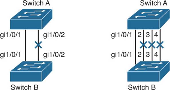
Figure 10-1 The Effects of Trying to Scale Bandwidth with Individual Links
Cisco offers another method of scaling link bandwidth by aggregating, or bundling, parallel links, termed the EtherChannel technology. Two to eight links of either Fast Ethernet (FE), Gigabit Ethernet (GE), or 10-Gigabit Ethernet (10GE) can be bundled as one logical link of Fast EtherChannel (FEC), Gigabit EtherChannel (GEC), or 10-Gigabit Etherchannel (10GEC), respectively. This bundle provides a full-duplex bandwidth of up to 1600 Mbps (eight links of Fast Ethernet), 16 Gbps (eight links of GE), or 160 Gbps (eight links of 10GE).
This also provides an easy means to “grow,” or expand, a link’s capacity between two switches, without having to continually purchase hardware for the next magnitude of throughput. For example, a single Fast Ethernet link (200 Mbps throughput) can be incrementally expanded up to eight Fast Ethernet links (1600 Mbps) as a single Fast EtherChannel. If the traffic load grows beyond that, the growth process can begin again with a single GE link (2 Gbps throughput), which can be expanded up to eight GE links as a Gigabit EtherChannel (16 Gbps). The process repeats again by moving to a single 10GE link, and so on.
Ordinarily, having multiple or parallel links between switches creates the possibility of bridging loops, an undesirable condition. EtherChannel avoids this situation by bundling parallel links into a single, logical link, which can act as either an access or a trunk link. Switches or devices on each end of the EtherChannel link must understand and use the EtherChannel technology for proper operation. Figure 10-2 demonstrates how the links added in Figure 10-1 can be configured as an EtherChannel bundle. All the bundled physical links are collectively known by the logical EtherChannel interface, port channel 1. Notice that none of the physical links are in the Blocking state; STP is aware of the single port channel interface, which is kept in the Forwarding state.

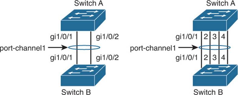
Figure 10-2 Scaling Bandwidth by Bundling Physical Links into an EtherChannel
Although an EtherChannel link is seen as a single logical link, the link does not necessarily have an inherent total bandwidth equal to the sum of its component physical links. For example, suppose that a GEC link is made up of four full-duplex 1-Gbps GE links. Although it is possible for the GEC link to carry a total throughput of 8 Gbps (if each link becomes fully loaded), the single resulting GEC bundle does not operate at this speed.
Instead, traffic is distributed across the individual links within the EtherChannel. Each of these links operates at its inherent speed (2 Gbps full duplex for GE) but carries only the frames placed on it by the EtherChannel hardware. If the load-distribution algorithm favors one link within the bundle, that link will carry a disproportionate amount of traffic. In other words, the load is not always distributed equally among the individual links. The load-balancing process is explained further in the next section.
EtherChannel also provides redundancy with several bundled physical links. If one of the links within the bundle fails, traffic sent through that link is automatically moved to an adjacent link. Failover occurs in less than a few milliseconds and is transparent to the end user. As more links fail, more traffic is moved to further adjacent links. Likewise, as links are restored, the load automatically is redistributed among the active links.
As you plan on configuring an EtherChannel, you should give some thought to several different failure scenarios. For example, the failure of a single physical link within an EtherChannel is not catastrophic because the switches compensate by moving traffic to the other, still functioning, links. However, what if all of the physical links are connected to the same switch, as shown in Figure 10-2? The switch itself might fail someday, taking all of the physical links of the EtherChannel down with it.
A more robust solution involves distributing the physical links across multiple switches at each end of the EtherChannel. This is possible when the switches are configured as one logical or virtual switch, such as the Cisco stackable Catalyst switches or chassis-based Virtual Switching System (VSS) switch families. In Figure 10-3, a four-port GEC is made up of two links connected to the first switch in a stack and two links connected to the second switch in a stack. This is known as a multichassis EtherChannel (MEC). Even if one switch fails within a stack, the MEC will keep functioning thanks to the other stacked switch.
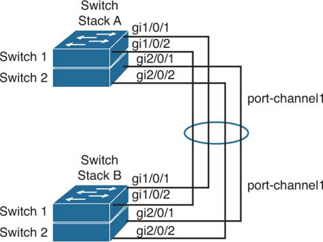
Figure 10-3 Increasing Availability with a Multichassis EtherChannel
Bundling Ports with EtherChannel
EtherChannel bundles can consist of up to eight physical ports of the same Ethernet media type and speed. Some configuration restrictions exist to ensure that only similarly configured links are bundled.
Generally, all bundled ports first must belong to the same VLAN. If used as a trunk, bundled ports must be in trunking mode, have the same native VLAN, and pass the same set of VLANs. Each of the ports should have the same speed and duplex settings before being bundled. Bundled ports also must be configured with identical spanning-tree settings.
Distributing Traffic in EtherChannel
Traffic in an EtherChannel is distributed across the individual bundled links in a deterministic fashion; however, the load is not necessarily balanced equally across all the links. Instead, frames are forwarded on a specific link as a result of a hashing algorithm. The algorithm can use source IP address, destination IP address, or a combination of source and destination IP addresses, source and destination MAC addresses, or TCP/UDP port numbers. The hash algorithm computes a binary pattern that selects a link number in the bundle to carry each frame.
If only one address or port number is hashed, a switch forwards each frame by using one or more low-order bits of the hash value as an index into the bundled links. If two addresses or port numbers are hashed, a switch performs an exclusive-OR (XOR) operation on one or more low-order bits of the addresses or TCP/UDP port numbers as an index into the bundled links.
For example, an EtherChannel consisting of two links bundled together requires a 1-bit index. If the index is 0, link 0 is selected; if the index is 1, link 1 is used. Either the lowest-order address bit or the XOR of the last bit of the addresses in the frame is used as the index. A four-link bundle uses a hash of the last 2 bits. Likewise, an eight-link bundle uses a hash of the last 3 bits. The hashing operation’s outcome selects the EtherChannel’s outbound link. Table 10-2 shows the results of an XOR on a two-link bundle, using the source and destination addresses.
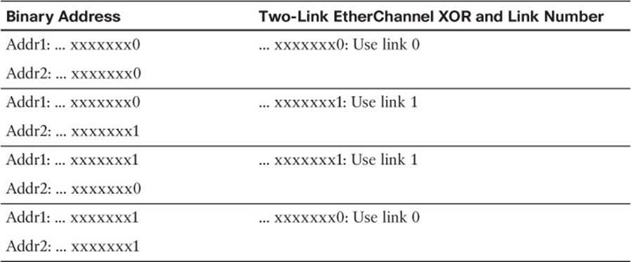
Table 10-2 Frame Distribution on a Two-Link EtherChannel
The XOR operation is performed independently on each bit position in the address value. If the two address values have the same bit value, the XOR result is always 0. If the two address bits differ, the XOR result is always 1. In this way, frames can be distributed statistically among the links with the assumption that MAC or IP addresses themselves are distributed statistically throughout the network. In a four-link EtherChannel, the XOR is performed on the lower 2 bits of the address values, resulting in a 2-bit XOR value (each bit is computed separately) or a link number from 0 to 3.
As an example, consider a packet being sent from IP address 192.168.1.1 to 172.31.67.46. Because EtherChannels can be built from two to eight individual links, only the rightmost (least-significant) 3 bits are needed as a link index. From the source and destination addresses, these bits are 001 (1) and 110 (6), respectively. For a two-link EtherChannel, a 1-bit XOR is performed on the rightmost address bit: 1 XOR 0 = 1, causing Link 1 in the bundle to be used. A four-link EtherChannel produces a 2-bit XOR: 01 XOR 10 = 11, causing Link 3 in the bundle to be used. Finally, an eight-link EtherChannel requires a 3-bit XOR: 001 XOR 110 = 111, where Link 7 in the bundle is selected.
A conversation between two devices always is sent through the same EtherChannel link because the two endpoint addresses stay the same. However, when a device talks to several other devices, chances are that the destination addresses are distributed equally with 0s and 1s in the last bit (even and odd address values). This causes the frames to be distributed across the EtherChannel links.
Note that the load distribution is still proportional to the volume of traffic passing between pairs of hosts or link indexes. For example, suppose that there are two pairs of hosts talking across a two-link channel, and each pair of addresses results in a unique link index. Frames from one pair of hosts always travel over one link in the channel, whereas frames from the other pair travel over the other link. The links are both being used as a result of the hash algorithm, so the load is being distributed across every link in the channel.
However, if one pair of hosts has a much greater volume of traffic than the other pair, one link in the channel will be used much more than the other. This still can create a load imbalance. To remedy this condition, you should consider other methods of hashing algorithms for the channel. For example, a method that combines the source and destination addresses along with UDP or TCP port numbers in a single XOR operation can distribute traffic much differently. Then, packets are placed on links within the bundle based on the applications (port numbers) used within conversations between two hosts. The possible hashing methods are discussed in the following section.
Configuring EtherChannel Load Balancing
The hashing operation can be performed on either MAC or IP addresses and can be based solely on source or destination addresses, or both. Use the following command to configure frame distribution for all EtherChannel switch links:
Switch(config)# port-channel load-balance method
Notice that the load-balancing method is set with a global configuration command. You must set the method globally for the switch, not on a per-port basis. Table 10-3 lists the possible values for the method variable, along with the hashing operation and some sample supporting switch models.
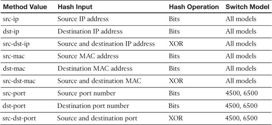
Table 10-3 Types of EtherChannel Load-Balancing Methods
The default configuration depends on the switch model and hardware capabilities. In common access layer switch models such as the Catalyst 3750-X, the default is src-mac. You can verify the load-balancing method currently in use with the show etherchannel load-balance command, as shown in Example 10-1.
Example 10-1 Displaying the Current EtherChannel Load-Balancing Method
Switch# show etherchannel load-balance
EtherChannel Load-Balancing Configuration:
src-mac
EtherChannel Load-Balancing Addresses Used Per-Protocol:
Non-IP: Source MAC address
IPv4: Source MAC address
IPv6: Source MAC address
Switch#
Normally, the default action should result in a statistical distribution of frames; however, you should determine whether the EtherChannel is imbalanced according to the traffic patterns present. For example, if a single server is receiving most of the traffic on an EtherChannel, the server’s address (the destination IP address) always will remain constant in the many conversations. This can cause one link to be overused if the destination IP address is used as a component of a load-balancing method. In the case of a four-link EtherChannel, perhaps two of the four links are overused. Configuring the use of MAC addresses, or only the source IP addresses, might cause the distribution to be more balanced across all the bundled links.
Tip
To verify how effectively a configured load-balancing method is performing, you can use the show etherchannel port-channel command. Each link in the channel is displayed, along with a hex “Load” value. Although this information is not intuitive, you can use the hex values to get an idea of each link’s traffic loads relative to the others.
In some applications, EtherChannel traffic might consist of protocols other than IP. For example, IPX or SNA frames might be switched along with IP. Non-IP protocols need to be distributed according to MAC addresses because IP addresses are not applicable. Here, the switch should be configured to use MAC addresses instead of the IP default.
Tip
A special case results when a router is connected to an EtherChannel. Recall that a router always uses its burned-in MAC address in Ethernet frames, even though it is forwarding packets to and from many different IP addresses. In other words, all the traffic sent by the router will use the router’s MAC address as the source. As well, many end stations send frames to their local router address with the router’s MAC address as the destination. This means that the destination MAC address is the same for all frames destined through the router.
Usually, this will not present a problem because the source MAC addresses are all different. When two routers are forwarding frames to each other, however, both source and destination MAC addresses remain constant, and only one link of the EtherChannel is used. If the MAC addresses remain constant, choose IP addresses instead. Beyond that, if most of the traffic is between the same two IP addresses, as in the case of two servers talking, choose IP port numbers to disperse the frames across different links.
You should choose the load-balancing method that provides the greatest distribution or variety when the channel links are indexed. Also consider the type of addressing that is being used on the network. If most of the traffic is IP, it might make sense to load balance according to IP addresses or TCP/UDP port numbers.
But if IP load balancing is being used, what happens to non-IP frames? If a frame cannot meet the load-balancing criteria, the switch automatically falls back to the “next lowest” method. With Ethernet, MAC addresses must always be present, so the switch distributes those frames according to their MAC addresses.
A switch also provides some inherent protection against bridging loops with EtherChannels. When ports are bundled into an EtherChannel, no inbound (received) broadcasts and multicasts are sent back out over any of the remaining ports in the channel. Outbound broadcast and multicast frames are load-balanced like any other: The broadcast or multicast address becomes part of the hashing calculation to choose an outbound channel link.
EtherChannel Negotiation Protocols
EtherChannels can be negotiated between two switches to provide some dynamic link configuration. Two protocols are available to negotiate bundled links in Catalyst switches. The Port Aggregation Protocol (PAgP) is a Cisco proprietary solution, and the Link Aggregation Control Protocol (LACP) is standards based. Table 10-4 summarizes the negotiation protocols and their operation.
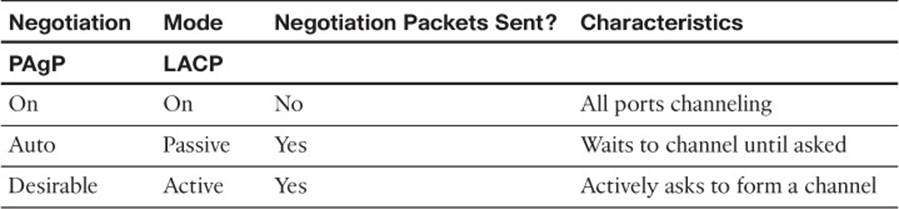
Table 10-4 EtherChannel Negotiation Protocols
Port Aggregation Protocol
To provide automatic EtherChannel configuration and negotiation between switches, Cisco developed the Port Aggregation Protocol. PAgP packets are exchanged between switches over EtherChannel-capable ports. Neighbors are identified and port group capabilities are learned and compared with local switch capabilities. Ports that have the same neighbor device ID and port group capability are bundled together as a bidirectional, point-to-point EtherChannel link.
PAgP forms an EtherChannel only on ports that are configured for either identical static VLANs or trunking. PAgP also dynamically modifies parameters of the EtherChannel if one of the bundled ports is modified. For example, if the configured VLAN, speed, or duplex mode of a port in an established bundle is changed, PAgP reconfigures that parameter for all ports in the bundle.
PAgP can be configured in active mode (desirable), in which a switch actively asks a far-end switch to negotiate an EtherChannel, or in passive mode (auto, the default), in which a switch negotiates an EtherChannel only if the far end initiates it.
Link Aggregation Control Protocol
LACP is a standards-based alternative to PAgP, defined in IEEE 802.3ad (also known as IEEE 802.3 Clause 43, “Link Aggregation”). LACP packets are exchanged between switches over EtherChannel-capable ports. As with PAgP, neighbors are identified and port group capabilities are learned and compared with local switch capabilities. However, LACP also assigns roles to the EtherChannel’s endpoints.
The switch with the lowest system priority (a 2-byte priority value followed by a 6-byte switch MAC address) is allowed to make decisions about what ports actively are participating in the EtherChannel at a given time.
Ports are selected and become active according to their port priority value (a 2-byte priority followed by a 2-byte port number), where a low value indicates a higher priority. A set of up to 16 potential links can be defined for each EtherChannel. Through LACP, a switch selects up to eight of these having the lowest port priorities as active EtherChannel links at any given time. The other links are placed in a standby state and will be enabled in the EtherChannel if one of the active links goes down.
Like PAgP, LACP can be configured in active mode (active), in which a switch actively asks a far-end switch to negotiate an EtherChannel, or in passive mode (passive), in which a switch negotiates an EtherChannel only if the far end initiates it.
EtherChannel Configuration
For each EtherChannel on a switch, you must choose the EtherChannel negotiation protocol and assign individual switch ports to the EtherChannel. Both PAgP- and LACP-negotiated EtherChannels are described in the following sections. You also can configure an EtherChannel to use the on mode, which unconditionally bundles the links. In this case, neither PAgP nor LACP packets are sent or received.
As ports are configured to be members of an EtherChannel, the switch automatically creates a logical port-channel interface. This interface represents the channel as a whole.
Configuring a PAgP EtherChannel
To configure switch ports for PAgP negotiation (the default), use the following commands:
Switch(config)# interface type member/module/number
Switch(config-if)# channel-protocol pagp
Switch(config-if)# channel-group number mode {on | {{auto | desirable}
[non-silent]}}
Each interface that will be included in a single EtherChannel bundle must be configured and assigned to the same unique channel group number (1 to 64). Channel negotiation must be set to on (unconditionally channel, no PAgP negotiation), auto (passively listen and wait to be asked), ordesirable (actively ask).
By default, PAgP operates in silent submode with the desirable and auto modes, and allows ports to be added to an EtherChannel even if the other end of the link is silent and never transmits PAgP packets. This might seem to go against the idea of PAgP, in which two endpoints are supposed to negotiate a channel. After all, how can two switches negotiate anything if no PAgP packets are received?
The key is in the phrase “if the other end is silent.” The silent submode listens for any PAgP packets from the far end, looking to negotiate a channel. If none is received, silent submode assumes that a channel should be built anyway, so no more PAgP packets are expected from the far end.
This allows a switch to form an EtherChannel with a device such as a file server or a network analyzer that does not participate in PAgP. In the case of a network analyzer connected to the far end, you also might want to see the PAgP packets generated by the switch, as if you were using a normal PAgP EtherChannel.
If you expect a PAgP-capable switch to be on the far end, you should add the non-silent keyword to the desirable or auto mode. This requires each port to receive PAgP packets before adding them to a channel. If PAgP is not heard on an active port, the port remains in the up state, but PAgP reports to the Spanning Tree Protocol (STP) that the port is down.
Tip
In practice, you might notice a delay from the time the links in a channel group are connected until the time the channel is formed and data can pass over it. You will encounter this if both switches are using the default PAgP auto mode and silent submode. Each interface waits to be asked to form a channel, and each interface waits and listens before accepting silent channel partners. The silent submode amounts to approximately a 15-second delay.
Even if the two interfaces are using PAgP auto mode, the link will still eventually come up, although not as a channel. You might notice that the total delay before data can pass over the link is actually approximately 45 or 50 seconds. The first 15 seconds are the result of PAgP silent mode waiting to hear inbound PAgP messages, and the final 30 seconds are the result of the STP moving through the listening and learning stages.
As an example of PAgP configuration, suppose that you want a switch to use an EtherChannel load-balancing hash of both source and destination port numbers. A Gigabit EtherChannel will be built from interfaces Gigabit Ethernet 1/0/1 through 1/0/4, with the switch actively negotiating a channel. The switch should not wait to listen for silent partners. You can use the following configuration commands to accomplish this:
Switch(config)# port-channel load-balance src-dst-port
Switch(config)# interface range gig 1/0/1 – 4
Switch(config-if)# channel-protocol pagp
Switch(config-if)# channel-group 1 mode desirable non-silent
Configuring a LACP EtherChannel
To configure switch ports for LACP negotiation, use the following commands:
Switch(config)# lacp system-priority priority
Switch(config)# interface type member/module/number
Switch(config-if)# channel-protocol lacp
Switch(config-if)# channel-group number mode {on | passive | active}
Switch(config-if)# lacp port-priority priority
First, the switch should have its LACP system priority defined (1 to 65,535; default 32,768). If desired, one switch should be assigned a lower system priority than the other so that it can make decisions about the EtherChannel’s makeup. Otherwise, both switches will have the same system priority (32,768), and the one with the lower MAC address will become the decision maker.
Each interface included in a single EtherChannel bundle must be assigned to the same unique channel group number (1 to 64). Channel negotiation must be set to on (unconditionally channel, no LACP negotiation), passive (passively listen and wait to be asked), or active (actively ask).
You can configure more interfaces in the channel group number than are allowed to be active in the channel. This prepares extra standby interfaces to replace failed active ones. Use the lacp port-priority command to configure a lower port priority (1 to 65,535; default 32,768) for any interfaces that must be active, and a higher priority for interfaces that might be held in the standby state. Otherwise, just use the default scenario, in which all ports default to 32,768 and the lower port numbers (in interface number order) are used to select the active ports.
As an example of LACP configuration, suppose that you want to configure a switch to negotiate a Gigabit EtherChannel using interfaces Gigabit Ethernet 1/0/1 through 1/0/4 and 2/0/1 through 2/0/4. Interfaces Gigabit Ethernet 1/0/5 through 1/0/8 and 2/0/5 through 2/0/8 are also available, so these can be used as standby links to replace failed links in the channel. This switch should actively negotiate the channel and should be the decision maker about the channel operation.
You can use the following configuration commands to accomplish this:
Switch(config)# lacp system-priority 100
Switch(config)# interface range gig 1/0/1 – 4 , gig 2/0/1 – 4
Switch(config-if)# channel-protocol lacp
Switch(config-if)# channel-group 1 mode active
Switch(config-if)# lacp port-priority 100
Switch(config-if)# exit
Switch(config)# interface range gig 1/0/5 – 8 , gig 2/0/5 – 8
Switch(config-if)# channel-protocol lacp
Switch(config-if)# channel-group 1 mode active
Notice that interfaces Gigabit Ethernet 1/0/5-8 and 2/0/5-8 have been left to their default port priorities of 32,768. This is higher than the others, which were configured for 100, so they will be held as standby interfaces.
Avoiding Misconfiguration with EtherChannel Guard
Once you configure a set of physical interfaces on one switch to participate in an EtherChannel, you should configure the corresponding interfaces on the neighboring switch. Your goal should be to keep the EtherChannel configurations as predictable as possible, so that nothing unexpected can happen,
What might happen anyway? Suppose that you configure two interfaces on Switch A to form an unconditional EtherChannel that carries all active VLANs. Your associate configures Switch B for the same set of two interfaces, but manages to plug the cables into the wrong two interfaces. It is entirely possible that a bridging loop might form over the dual links because an EtherChannel has not formed on both ends. STP will not operate consistently on all interfaces because Switch A is expecting a working EtherChannel.
If you decide to use PAgP or LACP to negotiate an EtherChannel, the chances of a misconfiguration are slim. An EtherChannel will not be built if it cannot be negotiated on all member links on the switches at both ends.
To reduce the chances of a misconfigured EtherChannel, Cisco Catalyst switches run the EtherChannel Guard feature by default. You can control the feature with the following global configuration command:
Switch(config)# [no] spanning-tree etherchannel guard misconfig
Notice that the command is directly related to STP operation over an EtherChannel. If a misconfiguration is detected once the interfaces are enabled, the switch will log the problem and will automatically shut the interfaces down and place them in the errdisable state.
In Example 10-2, two interfaces should have formed an EtherChannel, but a misconfiguration has been detected. Notice that both member interfaces, as well as the port channel 1 EtherChannel interface, have been errdisabled. To see the reason behind this action, you can use the show interfaces status err-disabled command.
Example 10-2 Detecting EtherChannel Misconfiguration with EtherChannel Guard
Mar 30 05:02:16.073: %PM-4-ERR_DISABLE: channel-misconfig (STP) error detected on
Gi1/0/25, putting Gi1/0/25 in err-disable state
Mar 30 05:02:16.081: %PM-4-ERR_DISABLE: channel-misconfig (STP) error detected on
Gi1/0/26, putting Gi1/0/26 in err-disable state
Mar 30 05:02:16.115: %PM-4-ERR_DISABLE: channel-misconfig (STP) error detected on
Po1, putting Gi1/0/25 in err-disable state
Mar 30 05:02:16.115: %PM-4-ERR_DISABLE: channel-misconfig (STP) error detected on
Po1, putting Gi1/0/26 in err-disable stning-ate
Mar 30 05:02:16.115: %PM-4-ERR_DISABLE: channel-misconfig (STP) error detected on
Po1, putting Po1 in err-disable state
Mar 30 05:02:17.079: %LINEPROTO-5-UPDOWN: Line protocol on Interface GigabitEther-
net1/0/25, changed state to down
Mar 30 05:02:17.096: %LINEPROTO-5-UPDOWN: Line protocol on Interface GigabitEther-
net1/0/26, changed state to down
Mar 30 05:02:17.104: %LINEPROTO-5-UPDOWN: Line protocol on Interface Port-channel1,
changed state to down
Switch# show interface status err-disabled
Port Name Status Reason Err-disabled Vlans
Gi1/0/25 err-disabled channel-misconfig (STP)
Gi1/0/26 err-disabled channel-misconfig (STP)
Po1 err-disabled channel-misconfig (STP)
Switch#
To recover from a misconfigured EtherChannel, first review the interface configuration on both switches. After you have corrected the problem, you must shut down the port channel interface and reenable it. The member interfaces will follow suit automatically, as shown in Example 10-3.
Example 10-3 Reenabling a Misconfigured EtherChannel
Switch(config)# interface port-channel1
Switch(config-if)# shutdown
Switch(config-if)# no shutdown
Switch(config-if)# ^Z
Switch#
Mar 30 05:09:21.518: %SYS-5-CONFIG_I: Configured from console by console
Mar 30 05:09:21.719: %LINK-3-UPDOWN: Interface GigabitEthernet1/0/25, changed state
to up
Mar 30 05:09:21.736: %LINK-3-UPDOWN: Interface GigabitEthernet1/0/26, changed state
to up
Mar 30 05:09:25.536: %LINEPROTO-5-UPDOWN: Line protocol on Interface GigabitEther-
net1/0/25, changed state to up
Mar 30 05:09:25.544: %LINEPROTO-5-UPDOWN: Line protocol on Interface GigabitEther-
net1/0/26, changed state to up
Mar 30 05:09:26.509: %LINK-3-UPDOWN: Interface Port-channel1, changed state to up
Mar 30 05:09:27.516: %LINEPROTO-5-UPDOWN: Line protocol on Interface Port-channel1,
changed state to up
Switch#
Troubleshooting an EtherChannel
If you find that an EtherChannel is having problems, remember that the whole concept is based on consistent configurations on both ends of the channel. Here are some reminders about EtherChannel operation and interaction:
![]() EtherChannel on mode does not send or receive PAgP or LACP packets. Therefore, both ends should be set to on mode before the channel can form.
EtherChannel on mode does not send or receive PAgP or LACP packets. Therefore, both ends should be set to on mode before the channel can form.
![]() EtherChannel desirable (PAgP) or active (LACP) mode attempts to ask the far end to bring up a channel. Therefore, the other end must be set to either desirable or auto mode.
EtherChannel desirable (PAgP) or active (LACP) mode attempts to ask the far end to bring up a channel. Therefore, the other end must be set to either desirable or auto mode.
![]() EtherChannel auto (PAgP) or passive (LACP) mode participates in the channel protocol, but only if the far end asks for participation. Therefore, two switches in the auto or passive mode will not form an EtherChannel.
EtherChannel auto (PAgP) or passive (LACP) mode participates in the channel protocol, but only if the far end asks for participation. Therefore, two switches in the auto or passive mode will not form an EtherChannel.
![]() PAgP desirable and auto modes default to the silent submode, in which no PAgP packets are expected from the far end. If ports are set to non-silent submode, PAgP packets must be received before a channel will form.
PAgP desirable and auto modes default to the silent submode, in which no PAgP packets are expected from the far end. If ports are set to non-silent submode, PAgP packets must be received before a channel will form.
First, verify the EtherChannel state with the show etherchannel summary command. Each port in the channel is shown, along with flags indicating the port’s state, as shown in Example 10-4.
Example 10-4 show etherchannel summary Command Output
Switch# show etherchannel summary
Flags: D - down P - in port-channel
I - stand-alone s - suspended
H - Hot-standby (LACP only)
R - Layer3 S - Layer2
u - unsuitable for bundling
U - in use f - failed to allocate aggregator
d - default port
Number of channel-groups in use: 1
Number of aggregators: 1
Group Port-channel Protocol Ports
------+--------------+-----------+------------------------------------------------
1 Po1(SU) LACP Gi1/0/1(P) Gi1/0/2(P) Gi1/0/3(D) Gi1/0/4(P)
Gi2/0/1(P) Gi2/0/2(P) Gi2/0/3(P) Gi2/0/4(P)
The status of the port channel shows the EtherChannel logical interface as a whole. This should show SU (Layer 2 channel, in use) if the channel is operational. You also can examine the status of each port within the channel. Notice that most of the channel ports have flags (P), indicating that they are active in the port-channel. One port shows (D) because it is physically not connected or down. If a port is connected but not bundled in the channel, it will have an independent, or (I), flag. You can verify the channel negotiation mode with the show etherchannel port command, as shown in Example 10-5. The local switch interface Gigabit Ethernet 1/0/25 is shown using LACP active mode. Notice that you also verify each end’s negotiation mode under the Flags heading—the local switch as A (active mode) and the partner, or far end switch, as P (passive mode).
Example 10-5 show etherchannel port Command Output
Switch# show etherchannel port
Channel-group listing:
----------------------
Group: 1
----------
Ports in the group:
-------------------
Port: Gi1/0/25
------------
Port state = Up Mstr Assoc In-Bndl
Channel group = 1 Mode = Active Gcchange = -
Port-channel = Po1 GC = - Pseudo port-channel = Po1
Port index = 0 Load = 0x00 Protocol = LACP
Flags: S - Device is sending Slow LACPDUs F - Device is sending fast LACPDUs.
A - Device is in active mode. P - Device is in passive mode.
Local information:
LACP port Admin Oper Port Port
Port Flags State Priority Key Key Number State
Gi1/0/25 SA bndl 32768 0x1 0x1 0x11A 0x3D
Partner's information:
LACP port Admin Oper Port Port
Port Flags Priority Dev ID Age key Key Number State
Gi1/0/25 SP 32768 aca0.164e.8280 21s 0x0 0x1 0x21A 0x3C
Age of the port in the current state: 0d:00h:02m:37s
[output truncated for clarity]
Within a switch, an EtherChannel cannot form unless each of the component or member ports is configured consistently. Each must have the same switch mode (access or trunk), native VLAN, trunked VLANs, port speed, port duplex mode, and so on.
You can display a port’s configuration by looking at the show running-config interface type mod/num output. Also, the show interface type member/module/number etherchannel shows all active EtherChannel parameters for a single port. If you configure a port inconsistently with others for an EtherChannel, you see error messages from the switch.
Some messages from the switch might look like errors but are part of the normal EtherChannel process. For example, as a new port is configured as a member of an existing EtherChannel, you might see this message:
4d00h: %EC-5-L3DONTBNDL2: GigabitEthernet1/0/11 suspended:
incompatible partner port with GigabitEthernet1/0/10
When the port is first added to the EtherChannel, it is incompatible because the STP runs on the channel and the new port. After STP takes the new port through its progression of states, the port is automatically added into the EtherChannel.
Other messages do indicate a port-compatibility error. In these cases, the cause of the error is shown. For example, the following message announces that Gigabit Ethernet1/0/3 has a different duplex mode than the other ports in the EtherChannel:
4d00h: %EC-5-CANNOT_BUNDLE2: GigabitEthernet1/0/3 is not compatible
with GigabitEthernet1/0/1 and will be suspended (duplex of Gi1/0/3
is full, Gi1/0/1 is half)
Finally, you can verify the EtherChannel load-balancing or hashing algorithm with the show etherchannel load-balance command. Remember that the switches on either end of an EtherChannel can have different load-balancing methods. The only drawback to this is that the load balancing will be asymmetric in the two directions across the channel.
Table 10-5 lists the commands useful for verifying or troubleshooting EtherChannel operation.
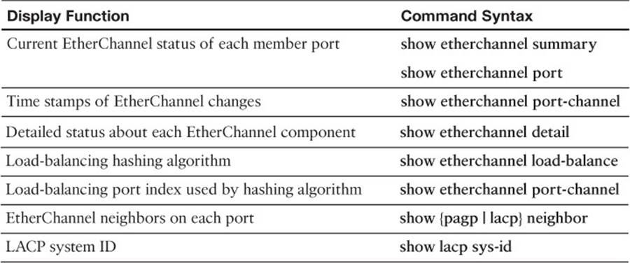
Table 10-5 EtherChannel Troubleshooting Commands
Exam Preparation Tasks
Review All Key Topics
Review the most important topics in the chapter, noted with the Key Topic icon in the outer margin of the page. Table 10-6 lists a reference of these key topics and the page numbers on which each is found.
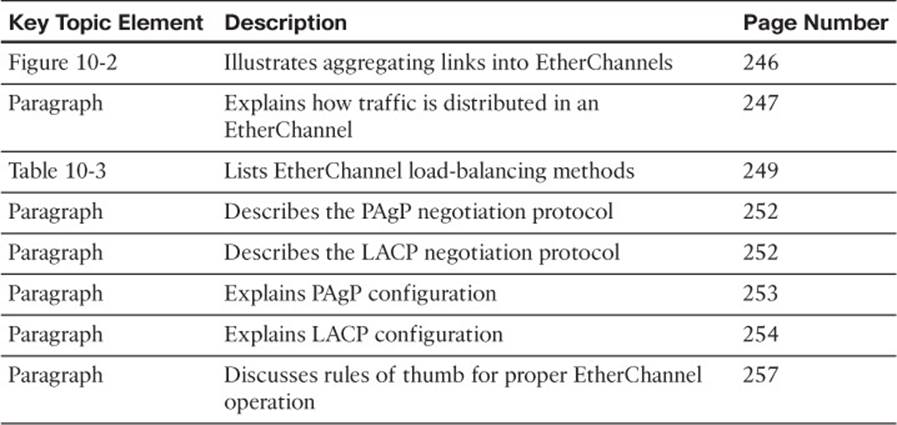
Table 10-6 Key Topics for Chapter 10
Complete Tables and Lists from Memory
Print a copy of Appendix C, “Memory Tables,” (found on the CD), or at least the section for this chapter, and complete the tables and lists from memory. Appendix D, “Memory Table Answer Key,” also on the CD, includes completed tables and lists to check your work.
Define Key Terms
Define the following key terms from this chapter, and check your answers in the glossary:
EtherChannel
PAgP
LACP
multichassis EtherChannel
EtherChannel Guard
Command Reference to Check Your Memory
This section includes the most important configuration and EXEC commands covered in this chapter. It might not be necessary to memorize the complete syntax of every command, but you should be able to remember the basic keywords that are needed.
To test your memory of the commands related to EtherChannels, cover the right side of Table 10-7 with a piece of paper, read the description on the left side, and then see how much of the command you can remember.
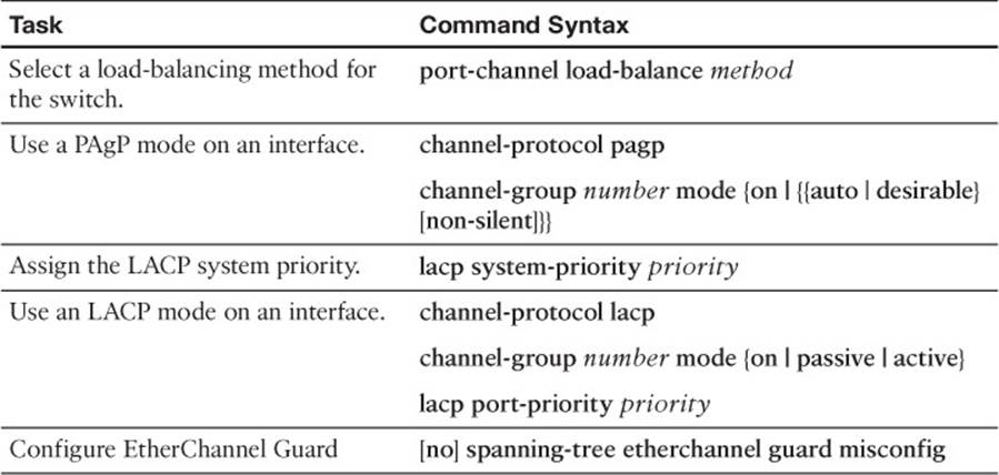
Table 10-7 EtherChannel Configuration Commands
Remember that the CCNP exam focuses on practical or hands-on skills that are used by a networking professional. For the skills covered in this chapter, remember that an EtherChannel is called a port channel interface when you are configuring it. When you are displaying information about an EtherChannel, begin the commands with the show etherchannel keywords.
All materials on the site are licensed Creative Commons Attribution-Sharealike 3.0 Unported CC BY-SA 3.0 & GNU Free Documentation License (GFDL)
If you are the copyright holder of any material contained on our site and intend to remove it, please contact our site administrator for approval.
© 2016-2026 All site design rights belong to S.Y.A.