CCNP Routing and Switching SWITCH 300-115 Official Cert Guide (2015)
Part VI. Implementing High Availability
Chapter 17. Understanding High Availability
This chapter covers the following topics that you need to master for the CCNP SWITCH exam:
![]() Leveraging Logical Switches: This section provides an overview of the StackWise and Virtual Switching System (VSS) techniques that can configure multiple physical switches into a single logical switch. The goals are improved network stability, efficiency, and scalability.
Leveraging Logical Switches: This section provides an overview of the StackWise and Virtual Switching System (VSS) techniques that can configure multiple physical switches into a single logical switch. The goals are improved network stability, efficiency, and scalability.
![]() Supervisor and Route Processor Redundancy: This section covers the methods that can be used on some Catalyst switch platforms to operate an active-standby pair of hardware modules in one chassis. The redundancy modes include route processor redundancy (RPR), RPR+, stateful switchover (SSO), and nonstop forwarding (NSF).
Supervisor and Route Processor Redundancy: This section covers the methods that can be used on some Catalyst switch platforms to operate an active-standby pair of hardware modules in one chassis. The redundancy modes include route processor redundancy (RPR), RPR+, stateful switchover (SSO), and nonstop forwarding (NSF).
This chapter describes the techniques that can make switching hardware more redundant and available. Multiple switches can be configured to act as a single logical switch. Within a single multilayer switch chassis, two supervisor modules with integrated route processors can be used to provide hardware redundancy. If one supervisor module fails, the other module can pick up the pieces and continue operating the switch.
“Do I Know This Already?” Quiz
The “Do I Know This Already?” quiz allows you to assess whether you should read this entire chapter thoroughly or jump to the “Exam Preparation Tasks” section. If you are in doubt based on your answers to these questions or your own assessment of your knowledge of the topics, read the entire chapter. Table 17-1 outlines the major headings in this chapter and the “Do I Know This Already?” quiz questions that go with them. You can find the answers in Appendix A, “Answers to the ‘Do I Know This Already?’ Quizzes.”
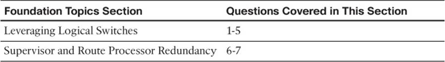
Table 17-1 “Do I Know This Already?” Foundation Topics Section-to-Question Mapping
1. Before a multichassis EtherChannel can be configured and used, which one of the following requirements must be met?
a. All the MEC links must connect to the same physical switch.
b. Only chassis-based switches like the Catalyst 4500 or 6500 can be used.
c. Physical switches must be configured as one logical switch.
d. Logical switches must be configured as one physical switch.
2. The term StackWise refers to which one of the following?
a. Switches that can be physically mounted or stacked upon each other
b. Multiple switches can share a common power bus for PoE
c. Switches that can stack packets and forward them more efficiently
d. Switches that can be configured as one logical switch
3. When StackWise switches are properly connected, they form which one of the following topologies?
a. A bidirectional ring
b. A hub and spoke
c. A star
d. An EtherChannel
4. Which one of the following features makes it possible for a switch to be added or removed from a StackWise switch stack without interrupting service?
a. NSF
b. SSO
c. Stacking ring
d. Multichassis EtherChannel
5. Which one of the following terms refers to two Catalyst 6500 switch chassis that are linked together and configured to act as a single logical switch?
a. RSS
b. VSS
c. ISL
d. SSO
6. Which one of the following features is used to reduce the amount of time needed to rebuild the routing information after a supervisor module failure?
a. NFS
b. NSF
c. RPR+
d. SSO
7. Which one of the following features provides the fastest failover for supervisor or route processor redundancy?
a. SSL
b. SSO
c. RPR+
d. RPR
Foundation Topics
Leveraging Logical Switches
In Chapter 1, “Enterprise Campus Network Design,” you learned that networks should be structured in distinct layers, in a modular fashion. Switches at each network layer should be implemented in pairs to provide redundancy in case of a device failure. Likewise, links between switch layers should be arranged in pairs to mitigate the effects of a link failure.
With so much redundancy and high availability, the network should be robust and efficient, right? Consider the network shown in Figure 17-1, which is a single switch block or module. In Chapters 6, “Traditional Spanning Tree Protocol,” through 9, “Advanced Spanning Tree Protocol,” you learned that the Spanning Tree Protocol (STP) will place some of the redundant links in Blocking mode, preventing bridging loop structures from forming. The end result is a network that still sports redundancy, but not every redundant link can be put to active use forwarding traffic.
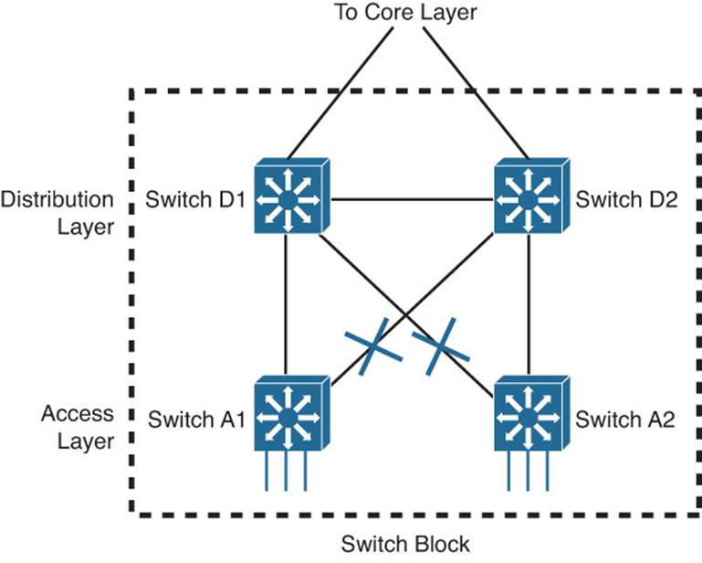
Figure 17-1 A Typical Redundant Network Design
Also notice that arranging the switches in pairs does provide switch redundancy, but only in the distribution and core layers. Pairs of access layer switches cannot provide redundancy for each other. In other words, users and their traffic can be spread across two access switches; if the CPU in one of the switches fails, however, the other switch cannot take over because the stranded users are not directly connected to it.
Having independent access switches also restricts some aspects of the access layer. Usually no direct link exists between two access switches, as shown in Figure 17-1. Therefore, each access switch should support a different VLAN for the end users. If there are many users fed out of one access layer room, you might have to use several switches and several different VLANs to maintain.
One way to improve the situation would be to somehow make two redundant physical switches into one logical switch. The single logical switch can group the redundant links into an EtherChannel, removing the dependence on STP to prevent loops and block links. In Figure 17-2, switches A1 and A2 are configured as one logical switch. The pairs of redundant links to the two distribution switches are configured as two EtherChannels. With no blocked links, all the links can actively transport traffic and increase the available bandwidth.
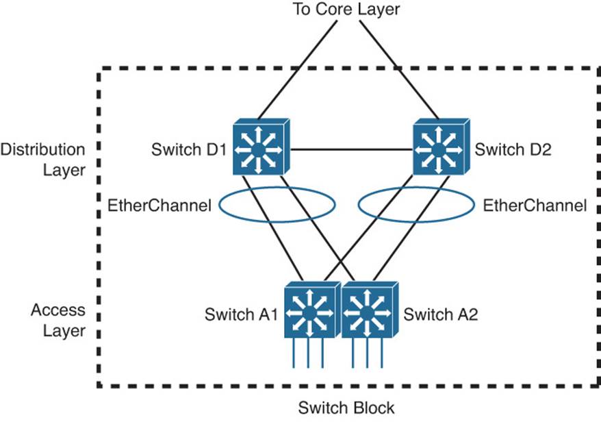
Figure 17-2 Improving Availability by Creating One Logical Switch from Two
Having one logical access switch also allows a single VLAN to be used to support the users. As well, you would have to manage and configure only one logical access switch, rather than two physical switches. The logical switch would support one logical control plane for management, while maintaining two separate data planes that are inherent within the physical switches.
Notice that the single logical access switch in Figure 17-2 still has two uplinks—one to each of the two distribution switches, organized as two EtherChannels. It is possible that one of the two EtherChannels might be blocked by STP or that only one of them will lead to the active gateway address upstream. In either case, all the links might not be fully used.
A further improvement would be to leverage the same logical switch scheme upstream in the distribution layer. As Figure 17-3 shows, the network architecture has been reduced to two logical switches (D1/D2 and A1/A2) that are connected by a single EtherChannel. All of the links can be used all the time. Even if one or more links fail, the rest of the EtherChannel will survive. With a single link between switches, STP should always keep it unblocked. The resulting topology becomes more stable because the EtherChannel will stay active even if STP fails or has a problem.
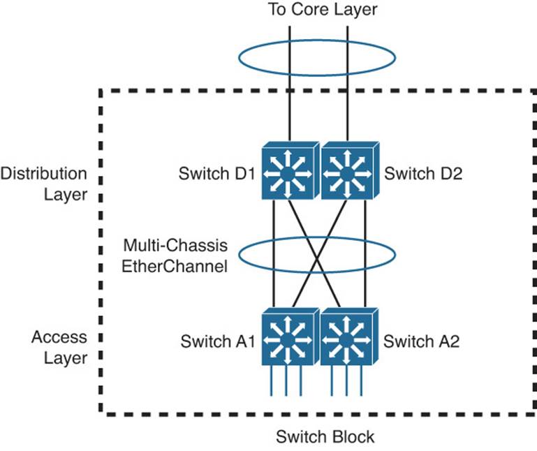
Figure 17-3 Connecting Two Logical Switches with an EtherChannel
To see how the logical switch architecture can simplify a whole network, compare the topologies shown in Figures 17-4 and 17-5. The former is full of redundant links to redundant switches, many not in use because STP blocked them. The latter has similar redundancy, but has a simple tree structure that STP will not have to alter.
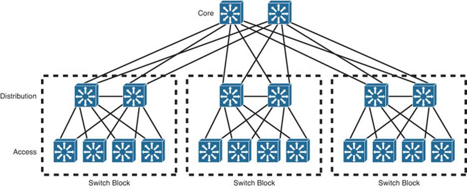
Figure 17-4 Traditional Redundant Switched Network Architecture
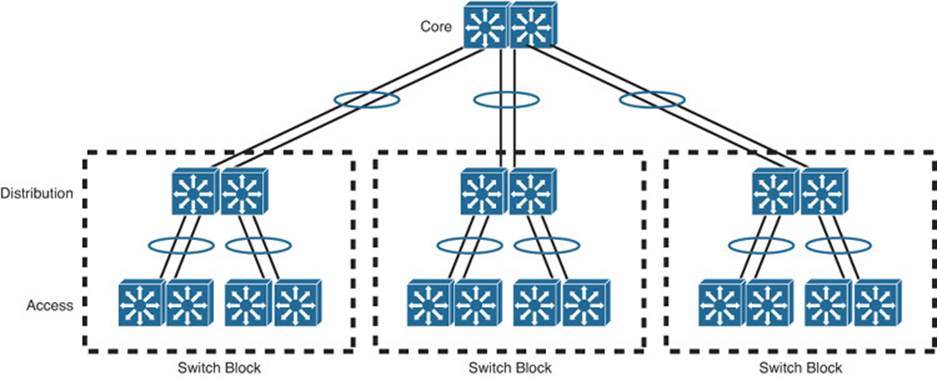
Figure 17-5 Enhanced Logical Switched Network Architecture
Cisco offers two approaches to building logical switches, which are discussed in the following sections.
StackWise
Traditionally, access layer switches have been independent physical devices. If you needed multiple switches in one location, you had to configure links between them. Cisco introduced the StackWise and StackWise Plus technologies to enable separate physical switches to act as a single logical switch. StackWise is available on switch models such as the Cisco Catalyst 3750-E, 3750-X, and 3850 platforms.
To create a logical “stacked” switch, individual physical switches must be connected to each other using special-purpose stacking cables. Each switch supports two stack ports; switches are connected in a daisy-chain fashion, one switch to the next, and one final connection connects the chain into a closed loop. You can think of the stacking cables as an extension of the switching fabric. When frames need to be moved from one physical switch to another, they are sent across the bidirectional stacking cable loop to get there. Figure 17-6 illustrates how two physical switches are cabled to become one logical stack. The same daisy-chain scheme can be used to connect up to nine physical switches in a closed ring fashion, as shown in Figure 17-7.

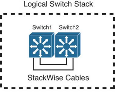
Figure 17-6 Creating a Logical Switch with StackWise
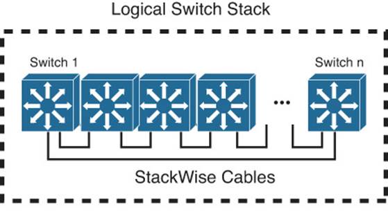
Figure 17-7 Extending StackWise to Include Multiple Physical Switches
One advantage of the closed stacking loop is that individual switches can be inserted or removed without breaking the path between switches completely. The ring can be broken to add or remove a switch, but the remaining switches stay connected over the rest of the ring. In other words, you can make changes to the stack without interrupting its operation.
When the physical switches are not part of a stack, each one operates independently and manages its own functions. When switches are connected as a stack, each one still maintains switching functionality, but only one switch becomes the stack master and performs all of the management functions. In fact, the whole stack is managed through a single IP address. If the master switch fails, other member switches can take over the role.
In Chapter 10, “Aggregating Switch Links,” you learned about multichassis EtherChannels (MECs). Ports on different physical switches in a stack can be bundled into a MEC. Even if one stack member fails, the MEC links connected to other stack members will stay up and functioning.
Virtual Switching System
Cisco also offers switches that are based on a chassis with slots that can contain multiple switching modules. The chassis must contain a supervisor module that handles all the switch management functions, including things like routing updates and forwarding tables. A chassis can also contain a redundant supervisor module, which can take over in case the current supervisor fails.
With platforms like the Cisco Catalyst 4500R, 6500, and 8500, you can configure two identical chassis to work as one logical switch. This is known as a Virtual Switching System (VSS), often called a VSS pair. One supervisor in one of the chassis controls the operation of the logical switch. If it fails, a supervisor in the other chassis can take over. To build the logical switch, the two chassis must be linked together by multiple interfaces that have been configured as a virtual switch link (VSL). Figure 17-8 shows two switch chassis operating as a VSS pair.
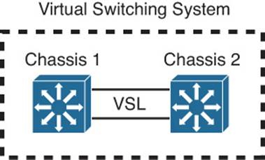
Figure 17-8 Configuring Two Identical Chassis to Work as One Logical Switch via VSS
Supervisor and Route Processor Redundancy
The Hot Standby Router Protocol (HSRP), Virtual Router Redundancy Protocol (VRRP), and Gateway Load Balancing Protocol (GLBP) router or gateway redundancy protocols covered in Chapter 18, “Layer 3 High Availability,” can provide high availability only for the default gateway addresses. If one of the redundant gateway routers fails, another can pick up the pieces and appear to be the same gateway address.
But what happens to the devices that are connected directly to the router that fails? If the switching or routing engine fails, packets probably will not get routed and interfaces will go down. Some Cisco switches have the capability to provide redundancy for the supervisor engine itself. This is accomplished by having redundant hardware in place within a switch chassis, ready to take over during a failure.
You also should consider switch power as a vital part of achieving high availability. For example, if a switch has a single power supply and a single power cord, the whole switch will fail if the power supply fails or if the power cord is accidentally unplugged. Some switch platforms can have multiple power supplies; if one power supply fails, another immediately takes over the load.
Redundant Switch Supervisors
Modular switch platforms such as the Catalyst 4500R, 6500, and 6800 can accept two supervisor modules installed in a single chassis. The first supervisor module to successfully boot becomes the active supervisor for the chassis. The other supervisor remains in a standby role, waiting for the active supervisor to fail.
The active supervisor always is allowed to boot and become fully initialized and operational. All switching functions are provided by the active supervisor. The standby supervisor, however, is allowed to boot and initialize only to a certain level. When the active module fails, the standby module can proceed to initialize any remaining functions and take over the active role.
Redundant supervisor modules can be configured in several modes. The redundancy mode affects how the two supervisors handshake and synchronize information. In addition, the mode limits the standby supervisor’s state of readiness. The more ready the standby module is allowed to become, the less initialization and failover time will be required.
You can use the following redundancy modes on Catalyst switches:

![]() Route processor redundancy (RPR): The redundant supervisor is only partially booted and initialized. When the active module fails, the standby module must reload every other module in the switch and then initialize all the supervisor functions.
Route processor redundancy (RPR): The redundant supervisor is only partially booted and initialized. When the active module fails, the standby module must reload every other module in the switch and then initialize all the supervisor functions.
![]() Route processor redundancy plus (RPR+): The redundant supervisor is booted, allowing the supervisor and route engine to initialize. No Layer 2 or Layer 3 functions are started, however. When the active module fails, the standby module finishes initializing without reloading other switch modules. This allows switch ports to retain their state.
Route processor redundancy plus (RPR+): The redundant supervisor is booted, allowing the supervisor and route engine to initialize. No Layer 2 or Layer 3 functions are started, however. When the active module fails, the standby module finishes initializing without reloading other switch modules. This allows switch ports to retain their state.
![]() Stateful switchover (SSO): The redundant supervisor is fully booted and initialized. Both the startup and running configuration contents are synchronized between the supervisor modules. Layer 2 information is maintained on both supervisors so that hardware switching can continue during a failover. The state of the switch interfaces is also maintained on both supervisors so that links do not flap during a failover.
Stateful switchover (SSO): The redundant supervisor is fully booted and initialized. Both the startup and running configuration contents are synchronized between the supervisor modules. Layer 2 information is maintained on both supervisors so that hardware switching can continue during a failover. The state of the switch interfaces is also maintained on both supervisors so that links do not flap during a failover.
Tip
Sometimes the redundancy mode terminology can be confusing. In addition to the RPR, RPR+, and SSO terms, you might see single-router mode (SRM) and dual-router mode (DRM).
SRM simply means that two route processors (integrated into the supervisors) are being used, but only one of them is active at any time. In DRM, two route processors are active at all times. HSRP usually is used to provide redundancy in DRM.
Although RPR and RPR+ have only one active supervisor, the route processor portion is not initialized on the standby unit. Therefore, SRM is not compatible with RPR or RPR+.
SRM is inherent with SSO, which brings up the standby route processor. You usually will find the two redundancy terms together, as “SRM with SSO.”
Configuring the Redundancy Mode
Table 17-2 details the redundancy modes you can configure on supported switch platforms.
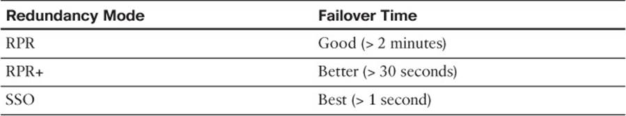
Table 17-2 Redundancy Modes and Failover Time
Figure 17-9 shows how the supervisor redundancy modes compare with respect to the functions they perform. The shaded functions are performed as the standby supervisor initializes and then waits for the active supervisor to fail. When a failure is detected, the remaining functions must be performed in sequence before the standby supervisor can become fully active. Notice how the redundancy modes get progressively more initialized and ready to become active.
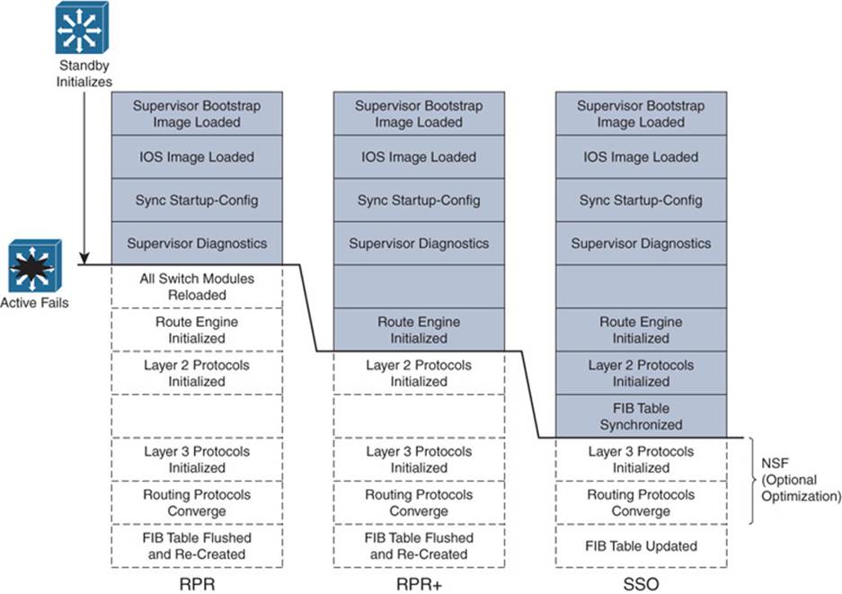
Figure 17-9 Standby Supervisor Readiness as a Function of Redundancy Mode
You can configure the supervisor redundancy mode by entering the redundancy configuration mode with the following command:
Switch(config)# redundancy
Next, select the redundancy mode with one of the following commands:
Switch(config-red)# mode {rpr | rpr-plus | sso}
If you are configuring redundancy for the first time on the switch, you must enter the previous commands on both supervisor modules. When the redundancy mode is enabled, you will make all configuration changes on the active supervisor only. The running configuration is synchronized automatically from the active to the standby module.
Tip
If you configure RPR+ with the rpr-plus keyword, the supervisor attempts to bring up RPR+ with its peer module. The IOS images must be of exactly the same release before RPR+ will work. If the images differ, the supervisor automatically falls back to RPR mode instead.
You can verify the redundancy mode and state of the supervisor modules by using the following command:
Switch# show redundancy states
The output in Example 17-1 shows that the switch is using RPR+ and that the second supervisor module (denoted by unit ID 2 and “my state”) holds the active role. The other supervisor module is in the standby state and is HOT, meaning that it has initialized as far as the redundancy mode will allow.
Example 17-1 Verifying Supervisor Module Redundancy Mode and State
Switch# show redundancy states
my state = 13 -ACTIVE
peer state = 8 -STANDBY HOT
Mode = Duplex
Unit = Secondary
Unit ID = 2
Redundancy Mode (Operational) = Route Processor Redundancy Plus
Redundancy Mode (Configured) = Route Processor Redundancy Plus
Split Mode = Disabled
Manual Swact = Enabled
Communications = Up
client count = 11
client_notification_TMR = 30000 milliseconds
keep_alive TMR = 9000 milliseconds
keep_alive count = 1
keep_alive threshold = 18
RF debug mask = 0x0
Switch#
Configuring Supervisor Synchronization
By default, the active supervisor synchronizes its startup configuration and configuration register values with the standby supervisor. You also can specify other information that should be synchronized.
First, use the following commands to enter the main-cpu configuration mode:
Switch(config)# redundancy
Switch(config-red)# main-cpu
Then use the following command to specify the information that will be synchronized:
Switch(config-r-mc)# auto-sync {startup-config | config-register | bootvar}
You can repeat the command if you need to use more than one of the keywords. To return to the default, use the auto-sync standard command.
Nonstop Forwarding
You can enable another redundancy feature along with SSO. Nonstop forwarding (NSF) is an interactive method that focuses on quickly rebuilding the Routing Information Base (RIB) table after a supervisor switchover. The RIB is used to generate the Forwarding Information Base (FIB) table for CEF, which is downloaded to any switch modules or hardware that can perform Cisco Express Forwarding (CEF).
Instead of waiting on any configured Layer 3 routing protocols to converge and rebuild the FIB, a router can use NSF to get assistance from other NSF-aware neighbors. The neighbors then can provide routing information to the standby supervisor, allowing the routing tables to be assembled quickly. In a nutshell, the Cisco proprietary NSF functions must be built in to the routing protocols on both the router that will need assistance and the router that will provide assistance.
NSF is supported by the Border Gateway Protocol (BGP), Enhanced Interior Gateway Routing Protocol (EIGRP), Open Shortest path First (OSPF), and Intermediate System-to-Intermediate System (IS-IS) routing protocols.
To configure NSF, you must add the commands in Table 17-3 to any routing protocol configuration on the switch.
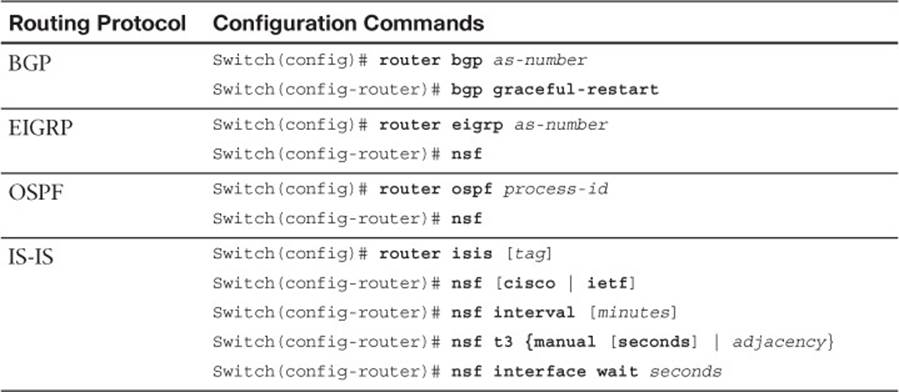
Table 17-3 Configuring NSF (by Routing Protocol)
Exam Preparation Tasks
Review All Key Topics
Review the most important topics in the chapter, noted with the Key Topic icon in the outer margin of the page. Table 17-4 lists a reference of these key topics and the page numbers on which each is found.

Table 17-4 Key Topics for Chapter 17
Complete Tables and Lists from Memory
Print a copy of Appendix C, “Memory Tables” (found on the CD), or at least the section for this chapter, and complete the tables and lists from memory. Appendix D, “Memory Table Answer Key,” also on the CD, includes completed tables and lists to check your work.
Define Key Terms
Define the following key terms from this chapter, and check your answers in the glossary:
StackWise
Virtual Switching System (VSS)
route processor redundancy (RPR)
route processor redundancy plus (RPR+)
stateful switchover (SSO)
nonstop forwarding (NSF)
Use Command Reference to Check Your Memory
This section includes the most important configuration and EXEC commands covered in this chapter. It might not be necessary to memorize the complete syntax of every command, but you should remember the basic keywords that are needed.
To test your memory of the configuration commands presented in this chapter, cover the right side of Tables 17-5 and 17-6 with a piece of paper, read the description on the left side, and then see how much of the command you can remember.
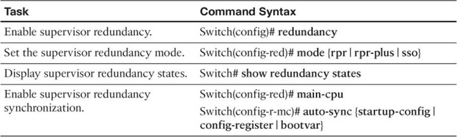
Table 17-5 Supervisor Redundancy Configuration Commands
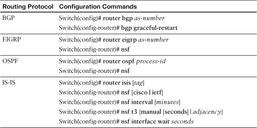
Table 17-6 Configuring NSF (by Routing Protocol)