CCNP Routing and Switching SWITCH 300-115 Official Cert Guide (2015)
Part VI. Implementing High Availability
Chapter 18. Layer 3 High Availability
This chapter covers the following first-hop redundancy protocols that you need to master for the CCNP SWITCH exam:
![]() Hot Standby Routing Protocol (HSRP)
Hot Standby Routing Protocol (HSRP)
![]() Virtual Router Redundancy Protocol (VRRP)
Virtual Router Redundancy Protocol (VRRP)
![]() Gateway Load Balancing Protocol (GLBP)
Gateway Load Balancing Protocol (GLBP)
A multilayer switch can provide routing functions for devices on a network, as described in Chapter 11, “Multilayer Switching.” If that switch happens to fail, clients have no way of having their traffic forwarded; their gateway has gone away.
Other multilayer switches can be added into the network to provide redundancy in the form of redundant router or gateway addresses. This chapter describes the protocols that can be used for redundant router addresses, load balancing across multiple routers, and load balancing into a server farm.
“Do I Know This Already?” Quiz
The “Do I Know This Already?” quiz allows you to assess whether you should read this entire chapter thoroughly or jump to the “Exam Preparation Tasks” section. If you are in doubt based on your answers to these questions or your own assessment of your knowledge of the topics, read the entire chapter. Table 18-1 outlines the major headings in this chapter and the “Do I Know This Already?” quiz questions that go with them. You can find the answers in Appendix A, “Answers to the ‘Do I Know This Already?’ Quizzes.”
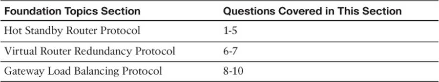
Table 18-1 “Do I Know This Already?” Foundation Topics Section-to-Question Mapping
1. Which one of the following do multilayer switches share when running HSRP?
a. Routing tables
b. ARP cache
c. CAM table
d. IP address
2. What HSRP group uses the MAC address 0000.0c07.ac11?
a. Group 0
b. Group 7
c. Group 11
d. Group 17
3. Two routers are configured for an HSRP group. One router uses the default HSRP priority. What priority should be assigned to the other router to make it more likely to be the active router?
a. 1
b. 100
c. 200
d. 500
4. How many routers are in the Standby state in an HSRP group?
a. 0
b. 1
c. 2
d. All but the active router
5. A multilayer switch is configured as follows:
interface gigabitethernet 1/0/1
no switchport
ip address 192.168.199.3 255.255.255.0
standby 1 ip 192.168.199.2
Which IP address should a client PC use as its default gateway?
a. 192.168.199.1
b. 192.168.199.2
c. 192.168.199.3
d. Any of these
6. Which one of the following is based on an IETF RFC standard?
a. HSRP
b. VRRP
c. GLBP
d. STP
7. What VRRP group uses the virtual MAC address 0000.5e00.01ff?
a. Group 0
b. Group 1
c. Group 255
d. Group 94
8. Which one of the following protocols is the best choice for load balancing redundant gateways?
a. HSRP
b. VRRP
c. GLBP
d. GVRP
9. Which one of the following GLBP functions answers ARP requests?
a. AVF
b. VARP
c. AVG
d. MVR
10. By default, which of the following virtual MAC addresses will be sent to the next client that looks for the GLBP virtual gateway?
a. The GLBP interface’s MAC address
b. The next virtual MAC address in the sequence
c. The virtual MAC address of the least-used router
d. 0000.0c07.ac00
Foundation Topics
Multilayer switches can act as IP gateways for connected hosts by providing gateway addresses at VLAN switch virtual interfaces (SVIs) and Layer 3 physical interfaces. These switches can also participate in routing protocols, just as traditional routers do.
For high availability, multilayer switches should offer a means of preventing one switch (gateway) failure from isolating an entire VLAN. This chapter discusses several approaches to providing router redundancy, including the following:
![]() Hot Standby Router Protocol (HSRP)
Hot Standby Router Protocol (HSRP)
![]() Virtual Router Redundancy Protocol (VRRP)
Virtual Router Redundancy Protocol (VRRP)
![]() Gateway Load Balancing Protocol (GLBP)
Gateway Load Balancing Protocol (GLBP)
These are also commonly called first-hop redundancy protocols (FHRP) because the first router hop is given high availability.
Packet-Forwarding Review
When a host must communicate with a device on its local subnet, it can generate an Address Resolution Protocol (ARP) request, wait for the ARP reply, and exchange packets directly. However, if the far end is located on a different subnet, the host must rely on an intermediate system (a router, for example) to relay packets to and from that subnet.
A host identifies its nearest router, also known as the default gateway or next hop, by its IP address. If the host understands something about routing, it recognizes that all packets destined off-net must be sent to the gateway’s MAC address rather than the far end’s MAC address. Therefore, the host first sends an ARP request to find the gateway’s MAC address. Then packets can be relayed to the gateway directly without having to look for ARP entries for individual destinations.
If the host is not so savvy about routing, it might still generate ARP requests for every off-net destination, hoping that someone will answer. Obviously, the off-net destinations cannot answer because they never receive the ARP request broadcasts; these requests are not forwarded across subnets. Instead, you can configure the gateway to provide a proxy ARP function so that it will reply to ARP requests with its own MAC address, as if the destination itself had responded.
Now the issue of gateway availability becomes important. If the gateway router for a subnet or VLAN goes down, packets have no way of being forwarded off the local subnet. Several protocols are available that allow multiple routing devices to share a common gateway address so that if one goes down, another automatically can pick up the active gateway role. The sections that follow describe these protocols.
Note
IPv6 offers some inherent gateway redundancy because every router connected to a subnet advertises its presence. Hosts overhear the advertisements and use the first router received. If that router fails, hosts have to wait up to 40 seconds to discover a replacement router—an inefficient process.
Hot Standby Router Protocol
HSRP is a Cisco proprietary protocol developed to allow several routers (or multilayer switches) to appear as a single gateway IP address. RFC 2281 describes this protocol in more detail.

Basically, each of the routers that provides redundancy for a given gateway address is assigned to a common HSRP group. One router is elected as the primary, or active, HSRP router; another is elected as the standby HSRP router; and all the others remain in the listen HSRP state. The routers exchange HSRP hello messages at regular intervals so that they can remain aware of each other’s existence and that of the active router.
Figure 18-1 shows a simple network in which two multilayer switches use HSRP Group 1 to provide the redundant gateway address 192.168.1.1. Switch A is the active router, with priority 200, and answers the ARP request for the gateway address. Because Switch B is in the Standby state, it never is used for traffic sent to 192.168.1.1. Instead, only Switch A performs the gateway routing function, and only its uplink to the access layer is utilized.
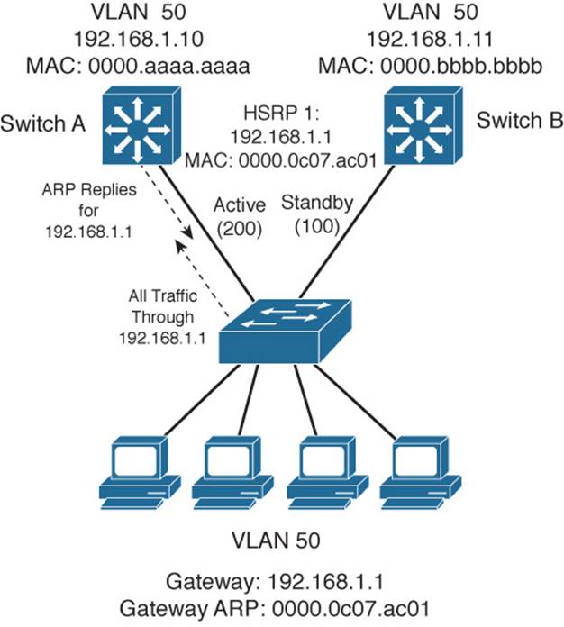
Figure 18-1 Typical HSRP Scenario with One HSRP Group
Note
HSRP sends its hello messages to the multicast destination 224.0.0.2 (“all routers”) using UDP port 1985.
An HSRP group can be assigned an arbitrary group number, from 0 to 255. If you configure HSRP groups on several VLAN interfaces, it can be handy to make the group number the same as the VLAN number. However, most Catalyst switches support only up to 16 unique HSRP group numbers. If you have more than 16 VLANs, you will quickly run out of group numbers. An alternative is to make the group number the same (that is, 1) for every VLAN interface. This is perfectly valid because the HSRP groups are locally significant only on an interface. In other words, HSRP Group 1 on interface VLAN 10 is unique and independent from HSRP Group 1 on interface VLAN 11.
HSRP Router Election
HSRP election is based on a priority value (0 to 255) that is configured on each router in the group. By default, the priority is 100. The router with the highest priority value (255 is highest) becomes the active router for the group. If all router priorities are equal or set to the default value, the router with the highest IP address on the HSRP interface becomes the active router. To set the priority, use the following interface configuration command:
Switch(config-if)# standby group priority priority
For example, suppose that one switch is left at its default priority of 100, while the local switch is intended to win the active role election. You can use the following command to set the HSRP priority to 200:
Switch(config-if)# standby 1 priority 200
When HSRP is configured on an interface, the router progresses through a series of states before becoming active. This forces a router to listen for others in a group and see where it fits into the pecking order. Devices participating in HSRP must progress their interfaces through the following state sequence:
1. Disabled
2. Init
3. Listen
4. Speak
5. Standby
6. Active
Only the standby (the one with the second-highest priority) router monitors the hello messages from the active router. By default, hellos are sent every 3 seconds. If hellos are missed for the duration of the Hold-Time timer (default 10 seconds, or three times the Hello timer), the active router is presumed to be down. The standby router is then clear to assume the active role.
At that point, if other routers are sitting in the Listen state, the next-highest priority router is allowed to become the new standby router.
If you need to change the timer values, use the following interface configuration command. If you decide to change the timers on a router, you should change them identically on all routers in the HSRP group.
Switch(config-if)# standby group timers [msec] hello [msec] holdtime
The hello and holdtime values can be given in seconds or in milliseconds, if the msec keyword precedes a value. The hello time can range from 1 to 254 seconds or from 15 to 999 milliseconds. The holdtime always should be at least three times the Hello timer and can range from 1 to 255 seconds or 50 to 3000 milliseconds.
For example, you can use the following command to set the hello time at 100 milliseconds and the hold time to 300 milliseconds:
Switch(config-if)# standby 1 timers msec 100 msec 300
Note
Be aware that decreasing the HSRP hello time allows a router failure to be detected more quickly. At the same time, HSRP hellos will be sent more often, increasing the amount of traffic on the interface.
Normally, after the active router fails and the standby becomes active, the original active router cannot immediately become active when it is restored. In other words, if a router is not already active, it cannot become active again until the current active router fails—even if its priority is higher than that of the active router. An interesting case arises when routers are just being powered up or added to a network. The first router to bring up its interface becomes the HSRP active router, even if it has the lowest priority of all.
You can configure a router to preempt or immediately take over the active role if its priority is the highest at any time. Use the following interface configuration command to allow preemption:
Switch(config-if)# standby group preempt [delay [minimum seconds] [reload
seconds]]
By default, the local router immediately can preempt another router that has the active role. To delay the preemption, use the delay keyword followed by one or both of the following parameters:
![]() Add the minimum keyword to force the router to wait for seconds (0 to 3600 seconds) before attempting to overthrow an active router with a lower priority. This delay time begins as soon as the router is capable of assuming the active role, such as after an interface comes up or after HSRP is configured.
Add the minimum keyword to force the router to wait for seconds (0 to 3600 seconds) before attempting to overthrow an active router with a lower priority. This delay time begins as soon as the router is capable of assuming the active role, such as after an interface comes up or after HSRP is configured.
![]() Add the reload keyword to force the router to wait for seconds (0 to 3600 seconds) after it has been reloaded or restarted. This is handy if there are routing protocols that need time to converge. The local router should not become the active gateway before its routing table is fully populated; otherwise, it might not be capable of routing traffic properly.
Add the reload keyword to force the router to wait for seconds (0 to 3600 seconds) after it has been reloaded or restarted. This is handy if there are routing protocols that need time to converge. The local router should not become the active gateway before its routing table is fully populated; otherwise, it might not be capable of routing traffic properly.
![]() HSRP also can use an authentication method to prevent unexpected devices from spoofing or participating in HSRP. All routers in the same standby group must have an identical authentication method and key. You can use either plain-text or MD5 authentication, as described in the following sections.
HSRP also can use an authentication method to prevent unexpected devices from spoofing or participating in HSRP. All routers in the same standby group must have an identical authentication method and key. You can use either plain-text or MD5 authentication, as described in the following sections.
Plain-Text HSRP Authentication
HSRP messages are sent with a plain-text key string (up to eight characters) as a simple method to authenticate HSRP peers. If the key string in a message matches the key configured on an HSRP peer, the message is accepted.
When keys are sent in the clear, they can be easily intercepted and used to impersonate legitimate peers. Plain-text authentication is intended only to prevent peers with a default configuration from participating in HSRP. Cisco devices use cisco as the default key string.
You can configure a plain-text authentication key for an HSRP group with the following interface configuration command:
Switch(config-if)# standby group authentication string
MD5 Authentication
A message digest 5 (MD5) authentication hash is computed on a portion of each HSRP message and a secret key known only to legitimate HSRP group peers. The MD5 hash value is sent along with HSRP messages. As a message is received, the peer recomputes the hash of the expected message contents and its own secret key; if the hash values are identical, the message is accepted.
MD5 authentication is more secure than plain-text authentication because the hash value contained in the HSRP messages is extremely difficult (if not impossible) to reverse. The hash value itself is not used as a key; instead, the hash is used to validate the message contents.
You can configure MD5 authentication by associating a key string with an interface, using the following interface configuration command:
Switch(config-if)# standby group authentication md5 key-string [0 | 7] string
By default, the key string (up to 64 characters) is given as plain text. This is the same as specifying the 0 keyword. After the key string is entered, it is shown as an encrypted value in the switch configuration. You also can copy and paste an encrypted key string value into this command by preceding the string with the 7 keyword.
Alternatively, you can define an MD5 key string as a key on a key chain. This method is more flexible, enabling you to define more than one key on the switch. Any of the keys then can be associated with HSRP on any interface. If a key needs to be changed, you simply add a new key to the key chain and retire (delete) an old key.
First define the key chain globally with the key chain command; then add one key at a time with the key and key-string commands. The key-number index is arbitrary, but keys are tried in sequential order. Finally, associate the key chain with HSRP on an interface by referencing its chain-name. You can use the following commands to configure HSRP MD5 authentication:
Switch(config)# key chain chain-name
Switch(config-keychain)# key key-number
Switch(config-keychain-key)# key-string [0 | 7] string
Switch(config)# interface type mod/num
Switch(config-if)# standby group authentication md5 key-chain chain-name
Conceding the Election
Consider an active router in an HSRP group: A group of clients sends packets to it for forwarding, and it has one or more links to the rest of the world. If one of those links fails, the router remains active. If all of those links fail, the router still remains active. But sooner or later, the path to the rest of the world is either crippled or removed, and packets from the clients no longer can be forwarded.
HSRP has a mechanism for detecting link failures and swaying the election, giving another router an opportunity to take over the active role. When a specific interface is tracked, HSRP reduces the router’s priority by a configurable amount as soon as the interface goes down. If more than one interface is tracked, the priority is reduced even more with each failed interface. The priority is incremented by the same amount as interfaces come back up.
This proves particularly useful when a switch has several paths out of a VLAN or subnet; as more interfaces fail and remove the possible paths, other HSRP peers should appear to be more desirable and take over the active role. To configure interface tracking, use the following interface configuration command:
Switch(config-if)# standby group track type mod/num [decrementvalue]
By default, the decrementvalue for an interface is 10. Keep in mind that interface tracking does not involve the state of the HSRP interface itself. Instead, the state of other specific interfaces affects the usefulness of the local router as a gateway. You also should be aware that the only way another router can take over the active role after interface tracking reduces the priority is if the following two conditions are met:
![]() Another router now has a higher HSRP priority.
Another router now has a higher HSRP priority.
![]() That same router is using preempt in its HSRP configuration.
That same router is using preempt in its HSRP configuration.
Without preemption, the active role cannot be given to any other router.
HSRP Gateway Addressing
Each router in an HSRP group has its own unique IP address assigned to an interface. This address is used for all routing protocol and management traffic initiated by or destined to the router. In addition, each router has a common gateway IP address, the virtual router address, which is kept alive by HSRP. This address also is referred to as the HSRP address or the standby address. Clients can point to that virtual router address as their default gateway, knowing that a router always keeps that address active. Keep in mind that the actual interface address and the virtual (standby) address must be configured to be in the same IP subnet.
You can assign the HSRP address with the following interface command:
Switch(config-if)# standby group ip ip-address [secondary]
When HSRP is used on an interface that has secondary IP addresses, you can add the secondary keyword so that HSRP can provide a redundant secondary gateway address.
Note
To use HSRP with IPv6, use the following commands to enable HSRP Version 2 and set the HSRP address:
Switch(config-if)# standby version 2
Switch(config-if)# standby ipv6 autoconfig
Naturally, each router keeps a unique MAC address for its interface. This MAC address is always associated with the unique IP address configured on the interface. For the virtual router address, HSRP defines a special MAC address of the form 0000.0c07.acxx, where xx represents the HSRP group number as a two-digit hex value. For example, HSRP Group 1 appears as 0000.0c07.ac01, HSRP Group 16 appears as 0000.0c07.ac10, and so on.
Example 18-1 shows the configuration commands you can use to configure switches A and B to implement the scenario shown in Figure 18-1.
Example 18-1 Configuring an HSRP Group on a Switch
Switch-A(config)# interface vlan 50
Switch-A(config-if)# ip address 192.168.1.10 255.255.255.0
Switch-A(config-if)# standby 1 priority 200
Switch-A(config-if)# standby 1 preempt
Switch-A(config-if)# standby 1 ip 192.168.1.1
Switch-A(config-if)# no shutdown
Switch-B(config)# interface vlan 50
Switch-B(config-if)# ip address 192.168.1.11 255.255.255.0
Switch-B(config-if)# standby 1 priority 100
Switch-B(config-if)# standby 1 preempt
Switch-B(config-if)# standby 1 ip 192.168.1.1
Switch-B(config-if)# no shutdown
Load Balancing with HSRP
Consider a network in which HSRP is used on two distribution switches to provide a redundant gateway address for access layer users. Only one of the two becomes the active HSRP router; the other remains in standby. All the users send their traffic to the active router over the uplink to the active router. The standby router and its uplink essentially sit idle until a router failure occurs.
Load balancing traffic across two uplinks to two HSRP routers with a single HSRP group is not possible. Then how is it possible to load balance with HSRP? The trick is to use two HSRP groups:
![]() One group assigns an active router to one switch.
One group assigns an active router to one switch.
![]() The other group assigns another active router to the other switch.
The other group assigns another active router to the other switch.
In this way, two different virtual router or gateway addresses can be used simultaneously. The rest of the trick is to make each switch function as the standby router for its partner’s HSRP group. In other words, each router is active for one group and standby for the other group. The clients or end users also must have their default gateway addresses configured as one of the two virtual HSRP group addresses.
Figure 18-2 presents this scenario. Now, Switch A is not only the active router for HSRP Group 1 (192.168.1.1), but it is also the standby router for HSRP Group 2 (192.168.1.2). Switch B is configured similarly, but with its roles reversed. The remaining step is to configure half of the client PCs with the HSRP Group 1 virtual router address and the other half with the Group 2 address. This makes load balancing possible and effective. Each half of the hosts uses one switch as its gateway over one uplink.
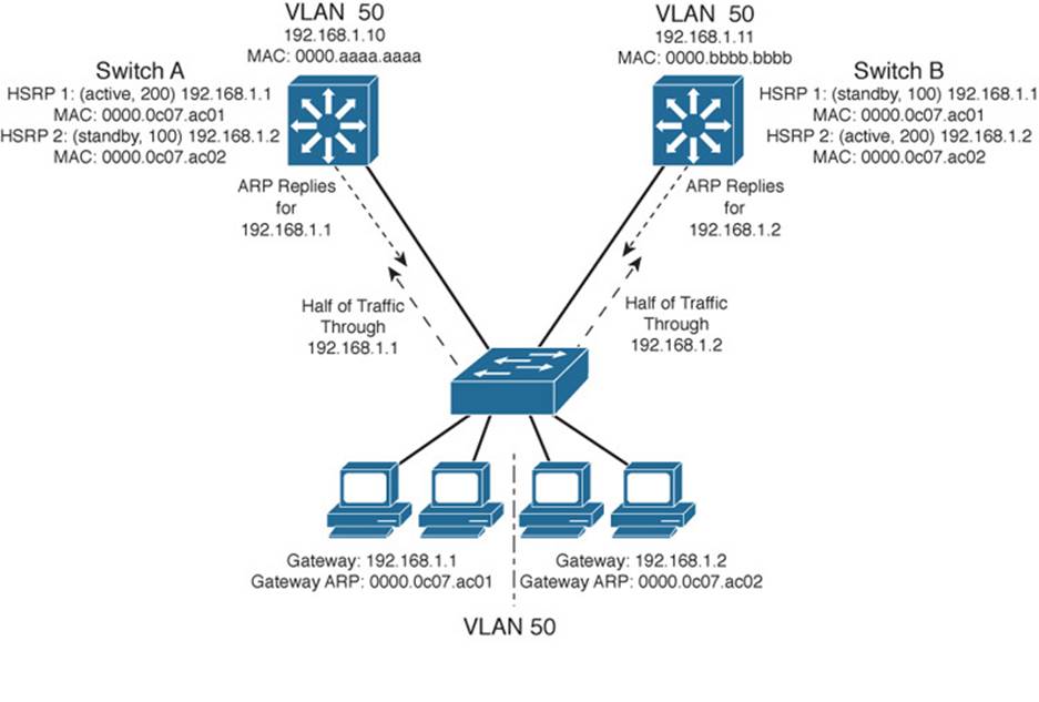
Figure 18-2 Load Balancing with Two HSRP Groups
Example 18-2 shows the configuration commands you can use for the scenario shown in Figure 18-2.
Example 18-2 Configuring Load Balancing Between HSRP Groups
Switch-A(config)# interface vlan 50
Switch-A(config-if)# ip address 192.168.1.10 255.255.255.0
Switch-A(config-if)# standby 1 priority 200
Switch-A(config-if)# standby 1 preempt
Switch-A(config-if)# standby 1 ip 192.168.1.1
Switch-A(config-if)# standby 1 authentication MyKey
Switch-A(config-if)# standby 2 priority 100
Switch-A(config-if)# standby 2 ip 192.168.1.2
Switch-A(config-if)# standby 2 authentication MyKey
Switch-B(config)# interface vlan 50
Switch-B(config-if)# ip address 192.168.1.11 255.255.255.0
Switch-B(config-if)# standby 1 priority 100
Switch-B(config-if)# standby 1 ip 192.168.1.1
Switch-B(config-if)# standby 1 authentication MyKey
Switch-B(config-if)# standby 2 priority 200
Switch-B(config-if)# standby 2 preempt
Switch-B(config-if)# standby 2 ip 192.168.1.2
Switch-B(config-if)# standby 2 authentication MyKey
You can use the following command to display information about the status of one or more HSRP groups and interfaces:
Router# show standby [brief] [vlan vlan-id | type mod/num]
Based on the configuration in Example 18-2, the output in Example 18-3 shows that Switch A is the active router for HSRP Group 1 and the standby router for HSRP Group 2 on interface VLAN 50.
Example 18-3 Displaying the HSRP Router Role of a Switch: Switch A
Switch-A# show standby vlan 50 brief
P indicates configured to preempt.
|
Interface Grp Prio P State Active addr Standby addr Group addr
Vl50 1 200 P Active local 192.168.1.11 192.168.1.1
Vl50 2 100 Standby 192.168.1.11 local 192.168.1.2
Switch-A#
Switch-A# show standby vlan 50
Vlan50 - Group 1
Local state is Active, priority 200, may preempt
Hellotime 3 sec, holdtime 10 sec
Next hello sent in 2.248
Virtual IP address is 192.168.1.1 configured
Active router is local
Standby router is 192.168.1.11 expires in 9.860
Virtual mac address is 0000.0c07.ac01
Authentication text "MyKey"
2 state changes, last state change 00:11:58
IP redundancy name is "hsrp-Vl50-1" (default)
Vlan50 - Group 2
Local state is Standby, priority 100
Hellotime 3 sec, holdtime 10 sec
Next hello sent in 1.302
Virtual IP address is 192.168.1.2 configured
Active router is 192.168.1.11, priority 200 expires in 7.812
Standby router is local
Authentication text "MyKey"
4 state changes, last state change 00:10:04
IP redundancy name is "hsrp-Vl50-2" (default)
Switch-A#
The output from Switch B in Example 18-4 shows that it has inverted roles from Switch A for HSRP Groups 1 and 2.
Example 18-4 Displaying the HSRP Router Role of a Switch: Switch B
Switch-B# show standby vlan 50 brief
P indicates configured to preempt.
|
Interface Grp Prio P State Active addr Standby addr Group addr
Vl50 1 100 Standby 192.168.1.10 local 192.168.1.1
Vl50 2 200 P Active local 192.168.1.10 192.168.1.2
Switch-B#
Switch-B# show standby vlan 50
Vlan50 - Group 1
Local state is Standby, priority 100
Hellotime 3 sec, holdtime 10 sec
Next hello sent in 0.980
Virtual IP address is 192.168.1.1 configured
Active router is 192.168.1.10, priority 200 expires in 8.128
Standby router is local
Authentication text "MyKey"
1 state changes, last state change 00:01:12
IP redundancy name is "hsrp-Vl50-1" (default)
Vlan50 - Group 2
Local state is Active, priority 200, may preempt
Hellotime 3 sec, holdtime 10 sec
Next hello sent in 2.888
Virtual IP address is 192.168.1.2 configured
Active router is local
Standby router is 192.168.1.10 expires in 8.500
Virtual mac address is 0000.0c07.ac02
Authentication text "MyKey"
1 state changes, last state change 00:01:16
Switch-B#
Virtual Router Redundancy Protocol
The Virtual Router Redundancy Protocol (VRRP) is a standards-based alternative to HSRP, defined in IETF standard RFC 2338. VRRP is so similar to HSRP that you need to learn only slightly different terminology and a couple of slight functional differences. When you understand HSRP operation and configuration, you will also understand VRRP. This section is brief, highlighting only the differences between HSRP and VRRP.
VRRP provides one redundant gateway address from a group of routers. The active router is called the master router, whereas all others are in the backup state. The master router is the one with the highest router priority in the VRRP group.
VRRP group numbers range from 0 to 255; router priorities range from 1 to 254. (254 is the highest, 100 is the default.)
The virtual router MAC address is of the form 0000.5e00.01xx, where xx is a two-digit hex VRRP group number.
VRRP advertisements are sent at 1-second intervals. Backup routers optionally can learn the advertisement interval from the master router.
By default, all VRRP routers are configured to preempt the current master router if their priorities are greater.
Note
VRRP sends its advertisements to the multicast destination address 224.0.0.18 (VRRP), using IP protocol 112. VRRP was introduced in Cisco IOS Software Release 12.0(18)ST for routers, but is not supported consistently across all switching platforms.
To configure VRRP, use the interface configuration commands documented in Table 18-2.
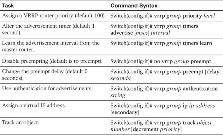
Table 18-2 VRRP Configuration Commands
As an example, the load-balancing scenario shown in Figure 18-2 is implemented using VRRP. You would use the configuration commands in Example 18-5 on the two Catalyst switches.
Example 18-5 Configuring Load Balancing with VRRP
Switch-A(config)# interface vlan 50
Switch-A(config-if)# ip address 192.168.1.10 255.255.255.0
Switch-A(config-if)# vrrp 1 priority 200
Switch-A(config-if)# vrrp 1 ip 192.168.1.1
Switch-A(config-if)# vrrp 2 priority 100
Switch-A(config-if)# no vrrp 2 preempt
Switch-A(config-if)# vrrp 2 ip 192.168.1.2
Switch-B(config)# interface vlan 50
Switch-B(config-if)# ip address 192.168.1.11 255.255.255.0
Switch-B(config-if)# vrrp 1 priority 100
Switch-B(config-if)# no vrrp 1 preempt
Switch-B(config-if)# vrrp 1 ip 192.168.1.1
Switch-B(config-if)# vrrp 2 priority 200
Switch-B(config-if)# vrrp 2 ip 192.168.1.2
You can use the following command to display information about VRRP status on one or more interfaces:
Switch# show vrrp [brief]
Example 18-6 shows this command executed on both Switch A and Switch B, with the output showing the alternating roles for the two VRRP groups configured in Example 18-5.
Example 18-6 Displaying Switch Roles for VRRP Load Balancing
Switch-A# show vrrp brief
Interface Grp Pri Time Own Pre State Master addr Group addr
Vlan50 1 200 3218 Y Master 192.168.1.10 192.168.1.1
Vlan50 2 100 3609 Backup 192.168.1.11 192.168.1.2
Switch-A#
Switch-B# show vrrp brief
Interface Grp Pri Time Own Pre State Master addr Group addr
Vlan50 1 100 3609 Backup 192.168.1.10 192.168.1.1
Vlan50 2 200 3218 Y Master 192.168.1.11 192.168.1.2
Switch-B#
Table 18-3 compares the detailed VRRP status between the Switch A and Switch B switches.
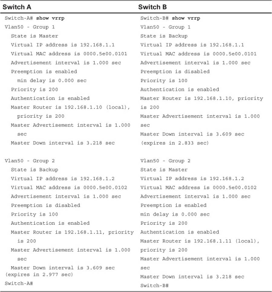
Table 18-3 Verifying VRRP Status for multiple VRRP Groups
Gateway Load Balancing Protocol
You should now know how both HSRP and VRRP can effectively provide a redundant gateway (virtual router) address. You can accomplish load balancing by configuring only multiple HSRP/VRRP groups to have multiple virtual router addresses. More manual configuration is needed so that the client machines are divided among the virtual routers. Each group of clients must point to the appropriate virtual router. This makes load balancing somewhat labor-intensive, having a more or less fixed, or static, behavior.
The Gateway Load Balancing Protocol (GLBP) is a Cisco proprietary protocol designed to overcome the limitations of existing redundant router protocols. Some of the concepts are the same as with HSRP/VRRP, but the terminology is different, and the behavior is much more dynamic and robust.
Note
GLBP was introduced in Cisco IOS Software Release 12.2(14)S for routers, but is not consistently supported across all switching platforms.
To provide a virtual router, multiple switches (routers) are assigned to a common GLBP group. Instead of having just one active router performing forwarding for the virtual router address, all routers in the group can participate and offer load balancing by forwarding a portion of the overall traffic.
The advantage is that none of the clients has to be pointed toward a specific gateway address; they can all have the same default gateway set to the virtual router IP address. The load balancing is provided completely through the use of virtual router MAC addresses in ARP replies returned to the clients. As a client sends an ARP request looking for the virtual router address, GLBP sends back an ARP reply with the virtual MAC address of a selected router in the group. The result is that all clients use the same gateway address but have differing MAC addresses for it.
Active Virtual Gateway
The trick behind this load balancing lies in the GLBP group. One router is elected the active virtual gateway (AVG). This router has the highest priority value, or the highest IP address in the group, if there is no highest priority. The AVG answers all ARP requests for the virtual router address. Which MAC address it returns depends on which load-balancing algorithm it is configured to use. In any event, the virtual MAC address supported by one of the routers in the group is returned.
The AVG also assigns the necessary virtual MAC addresses to each of the routers participating in the GLBP group. Up to four virtual MAC addresses can be used in any group. Each of these routers is referred to as an active virtual forwarder (AVF), forwarding traffic received on its virtual MAC address. Other routers in the group serve as backup or secondary virtual forwarders, in case the AVF fails. The AVG also assigns secondary roles.
Assign the GLBP priority to a router with the following interface configuration command:
Switch(config-if)# glbp group priority level
GLBP group numbers range from 0 to 1023. The router priority can be 1 to 255 (255 is the highest priority), defaulting to 100.
As with HSRP, another router cannot take over an active role until the current active router fails. GLBP does allow a router to preempt and become the AVG if it has a higher priority than the current AVG. Use the following command to enable preempting and to set a time delay before preempting begins:
Switch(config-if)# glbp group preempt [delay minimum seconds]
Routers participating in GLBP must monitor each other’s presence so that another router can assume the role of a failed router. To do this, the AVG sends periodic hello messages to each of the other GLBP peers. In addition, it expects to receive hello messages from each of them.
Hello messages are sent at hellotime intervals, with a default of 3 seconds. If hellos are not received from a peer within a holdtime, defaulting to 10 seconds, that peer is presumed to have failed. You can adjust the GLBP timers with the following interface configuration command:
Switch(config-if)# glbp group timers [msec] hellotime [msec] holdtime
The timer values normally are given in seconds, unless they are preceded by the msec keyword, to indicate milliseconds. The hellotime can range from 1 to 60 seconds or from 50 to 60,000 milliseconds. The holdtime must be greater than the hellotime and can go up to 180 seconds or 180,000 milliseconds. You always should make the holdtime at least three times greater than the hellotime to give some tolerance to missed or delayed hellos from a functional peer.
Tip
Although you can use the previous command to configure the GLBP timers on each peer router, it is not necessary. Instead, just configure the timers on the router you have identified as the AVG. The AVG will advertise the timer values it is using, and every other peer will learn those values if they have not already been explicitly set.
Active Virtual Forwarder
Each router participating in the GLBP group can become an AVF, if the AVG assigns it that role, along with a virtual MAC address. The virtual MAC addresses always have the form 0007.b4xx.xxyy. The 16-bit value denoted by xx.xx represents six 0 bits followed by a 10-bit GLBP group number. The 8-bit yy value is the virtual forwarder number.
By default, GLBP uses the periodic hello messages to detect AVF failures, too. Each router within a GLBP group must send hellos to every other GLBP peer. Hellos also are expected from every other peer. For example, if hellos from the AVF are not received by the AVG before its Hold-Time timer expires, the AVG assumes that the current AVF has failed. The AVG then assigns the AVF role to another router.
Naturally, the router that is given the new AVF role might already be an AVF for a different virtual MAC address. Although a router can masquerade as two different virtual MAC addresses to support the two AVF functions, it does not make much sense to continue doing that for a long period of time. The AVG maintains two timers that help resolve this condition.
The redirect timer is used to determine when the AVG will stop using the old virtual MAC address in ARP replies. The AVF corresponding to the old address continues to act as a gateway for any clients that try to use it.
When the timeout timer expires, the old MAC address and the virtual forwarder using it are flushed from all the GLBP peers. The AVG assumes that the previously failed AVF will not return to service, so the resources assigned to it must be reclaimed. At this point, clients still using the old MAC address in their ARP caches must refresh the entry to obtain the new virtual MAC address.
The redirect timer defaults to 600 seconds (10 minutes) and can range from 0 to 3600 seconds (1 hour). The timeout timer defaults to 14,400 seconds (4 hours) and can range from 700 to 64,800 seconds (18 hours). You can adjust these timers with the following interface configuration command:
Switch(config-if)# glbp group timers redirect redirect timeout
GLBP also can use a weighting function to determine which router becomes the AVF for a virtual MAC address in a group. Each router begins with a maximum weight value (1 to 254). As specific interfaces go down, the weight is decreased by a configured amount. GLBP uses thresholds to determine when a router can and cannot be the AVF. If the weight falls below the lower threshold, the router must give up its AVF role. When the weight rises above the upper threshold, the router can resume its AVF role.
By default, a router receives a maximum weight of 100. If you want to make a dynamic weighting adjustment, GLBP must know which interfaces to track and how to adjust the weight. You must first define an interface as a tracked object with the following global configuration command:
Switch(config)# track object-number interface type member/module/number {line-
protocol | ip routing}
The object-number is an arbitrary index (1 to 500) that is used for weight adjustment. The condition that triggers an adjustment can be line-protocol (the interface line protocol is up) or ip routing. (IP routing is enabled, the interface has an IP address, and the interface is up.)
Next, you must define the weighting thresholds for the interface with the following interface configuration command:
Switch(config-if)# glbp group weighting maximum [lower lower] [upper upper]
The maximum weight can range from 1 to 254 (default 100). The upper (default maximum) and lower (default 1) thresholds define when the router can and cannot be the AVF, respectively.
Finally, you must configure GLBP to know which objects to track so that the weighting can be adjusted with the following interface configuration command:
Switch(config-if)# glbp group weighting track object-number [decrement value]
When the tracked object fails, the weighting is decremented by value (1 to 254, default 10).
Likewise, a router that might serve as an AVF cannot preempt another when it has a higher weight value.
GLBP Load Balancing
The AVG establishes load balancing by handing out virtual router MAC addresses to clients in a deterministic fashion. Naturally, the AVG first must inform the AVFs in the group of the virtual MAC address that each should use. Up to four virtual MAC addresses, assigned in sequential order, can be used in a group.
You can use one of the following load-balancing methods in a GLBP group:
![]() Round robin: Each new ARP request for the virtual router address receives the next available virtual MAC address in reply. Traffic load is distributed evenly across all routers participating as AVFs in the group, assuming that each of the clients sends and receives the same amount of traffic. This is the default method used by GLBP.
Round robin: Each new ARP request for the virtual router address receives the next available virtual MAC address in reply. Traffic load is distributed evenly across all routers participating as AVFs in the group, assuming that each of the clients sends and receives the same amount of traffic. This is the default method used by GLBP.
![]() Weighted: The GLBP group interface’s weighting value determines the proportion of traffic that should be sent to that AVF. A higher weighting results in more frequent ARP replies containing the virtual MAC address of that router. If interface tracking is not configured, the maximum weighting value configured is used to set the relative proportions among AVFs.
Weighted: The GLBP group interface’s weighting value determines the proportion of traffic that should be sent to that AVF. A higher weighting results in more frequent ARP replies containing the virtual MAC address of that router. If interface tracking is not configured, the maximum weighting value configured is used to set the relative proportions among AVFs.
![]() Host dependent: Each client that generates an ARP request for the virtual router address always receives the same virtual MAC address in reply. This method is used if the clients have a need for a consistent gateway MAC address. (Otherwise, a client could receive replies with different MAC addresses for the router over time, depending on the load-balancing method in use.)
Host dependent: Each client that generates an ARP request for the virtual router address always receives the same virtual MAC address in reply. This method is used if the clients have a need for a consistent gateway MAC address. (Otherwise, a client could receive replies with different MAC addresses for the router over time, depending on the load-balancing method in use.)
On the AVG router (or its successors), use the following interface configuration command to define the method:
Switch(config-if)# glbp group load-balancing [round-robin | weighted |
host-dependent]
Enabling GLBP
To enable GLBP, you must assign a virtual IP address to the group by using the following interface configuration command:
Switch(config-if)# glbp group ip [ip-address [secondary]]
If the ip-address is not given in the command, it is learned from another router in the group. However, if this router is to be the AVG, you must explicitly configure the IP address; otherwise, no other router knows what the value should be.
Note
GLBP can also be used with IPv6. Rather than specifying an IPv6 address, use the following command to autoconfigure the address:
Switch(config-if)# glbp group ipv6 autoconfigure
Figure 18-3 shows a typical network in which three multilayer switches are participating in a common GLBP group. Switch A is elected the AVG, so it coordinates the entire GLBP process. The AVG answers all ARP requests for the virtual router 192.168.1.1. It has identified itself, Switch B, and Switch C as AVFs for the group.
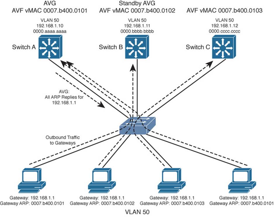
Figure 18-3 Multilayer Switches in a GLBP Group
In this figure, round-robin load balancing is being used. Each of the client PCs sends an ARP request to look for the virtual router address (192.168.1.1) in turn, from left to right. Each time the AVG replies, the next sequential virtual MAC address is sent back to a client. After the fourth PC sends a request, all three virtual MAC addresses (and AVF routers) have been used, so the AVG cycles back to the first virtual MAC address.
Notice that only one GLBP group has been configured, and all clients know of only one gateway IP address: 192.168.1.1. However, all uplinks are being used, and all routers are proportionately forwarding traffic.
Redundancy is also inherent in the GLBP group: Switch A is the AVG, but the next-highest priority router can take over if the AVG fails. All routers have been given an AVF role for a unique virtual MAC address in the group. If one AVF fails, some clients remember the last-known virtual MAC address that was handed out. Therefore, another of the routers also takes over the AVF role for the failed router, causing the virtual MAC address to remain alive at all times.
Figure 18-4 shows how these redundancy features react when the current active AVG fails. Before its failure, Switch A was the AVG because of its higher GLBP priority. After it failed, Switch B became the AVG, answering ARP requests with the appropriate virtual MAC address for gateway 192.168.1.1. Switch A also had been acting as an AVF, participating in the gateway load balancing. Switch B also picks up this responsibility, using its virtual MAC address 0007.b400.0102 along with the one Switch A had been using, 0007.b400.0101. Therefore, any hosts that know the gateway by any of its virtual MAC addresses still can reach a live gateway or AVF.
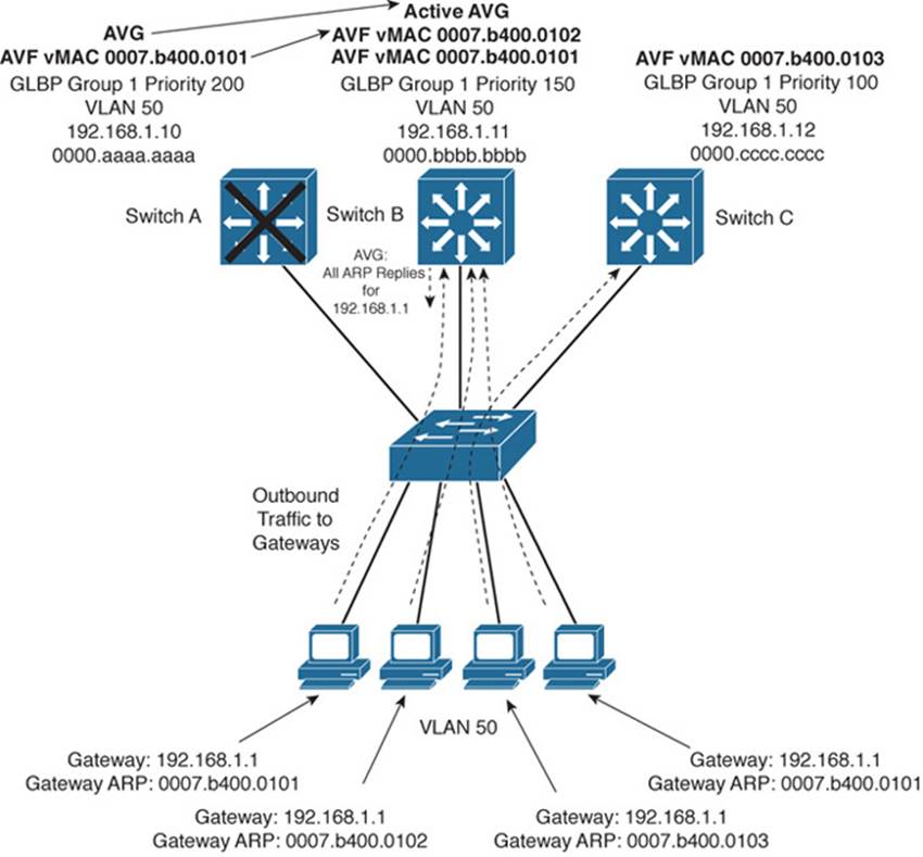
Figure 18-4 How GLBP Reacts to a Component Failure
You can implement the scenario shown in Figures 18-3 and 18-4 with the configuration commands in Example 18-7 for Switch A, Switch B, and Switch C, respectively.
Example 18-7 Configuring GLBP Load Balancing
Switch-A(config)# interface vlan 50
Switch-A(config-if)# ip address 192.168.1.10 255.255.255.0
Switch-A(config-if)# glbp 1 priority 200
Switch-A(config-if)# glbp 1 preempt
Switch-A(config-if)# glbp 1 ip 192.168.1.1
Switch-B(config)# interface vlan 50
Switch-B(config-if)# ip address 192.168.1.11 255.255.255.0
Switch-B(config-if)# glbp 1 priority 150
Switch-B(config-if)# glbp 1 preempt
Switch-B(config-if)# glbp 1 ip 192.168.1.1
Switch-C(config)# interface vlan 50
Switch-C(config-if)# ip address 192.168.1.12 255.255.255.0
Switch-C(config-if)# glbp 1 priority 100
Switch-C(config-if)# glbp 1 ip 192.168.1.1
You can verify GLBP operation with the show glbp [brief] command, as demonstrated in Example 18-8. With the brief keyword, the GLBP roles are summarized showing the interface, GLBP group number (Grp), virtual forwarder number (Fwd), GLBP priority (Pri), state, and addresses.
Example 18-8 Verifying GLBP Operation
Switch-A# show glbp brief
Interface Grp Fwd Pri State Address Active router Standby router
Vl50 1 - 200 Active 192.168.1.1 local 192.168.1.11
Vl50 1 1 7 Active 0007.b400.0101 local -
Vl50 1 2 7 Listen 0007.b400.0102 192.168.1.11 -
Vl50 1 3 7 Listen 0007.b400.0103 192.168.1.12 -
Switch-A#
Switch-B# show glbp brief
Interface Grp Fwd Pri State Address Active router Standby router
Vl50 1 - 150 Standby 192.168.1.1 192.168.1.10 local
Vl50 1 1 7 Listen 0007.b400.0101 192.168.1.10 -
Vl50 1 2 7 Active 0007.b400.0102 local -
Vl50 1 3 7 Listen 0007.b400.0103 192.168.1.12 -
Switch-B#
Switch-C# show glbp brief
Interface Grp Fwd Pri State Address Active router Standby router
Vl50 1 - 100 Listen 192.168.1.1 192.168.1.10 192.168.1.11
Vl50 1 1 7 Listen 0007.b400.0101 192.168.1.10 -
Vl50 1 2 7 Listen 0007.b400.0102 192.168.1.11 -
Vl50 1 3 7 Active 0007.b400.0103 local -
Switch-C#
Notice that Switch A is shown to be the AVG because it has a dash in the Fwd column and is in the Active state. It also is acting as AVF for virtual forwarder number 1. Because the GLBP group has three routers, there are three virtual forwarders and virtual MAC addresses. Switch A is in the Listen state for forwarders number 2 and 3, waiting to be given an active role in case one of those AVFs fails.
Switch B is shown to have the Standby role, waiting to take over in case the AVG fails. It is the AVF for virtual forwarder number 2.
Finally, Switch C has the lowest GLBP priority, so it stays in the Listen state, waiting for the active or standby AVG to fail. It is also the AVF for virtual forwarder number 3.
You also can display more detailed information about the GLBP configuration and status by omitting the brief keyword. Example 18-9 shows this output on the AVG router. Because this is the AVG, the virtual forwarder roles it has assigned to each of the routers in the GLBP group also are shown.
Example 18-9 Displaying Detailed GLBP Configuration and Status Information
Switch-A# show glbp
Vlan50 - Group 1
State is Active
7 state changes, last state change 03:28:05
Virtual IP address is 192.168.1.1
Hello time 3 sec, hold time 10 sec
Next hello sent in 1.672 secs
Redirect time 600 sec, forwarder time-out 14400 sec
Preemption enabled, min delay 0 sec
Active is local
Standby is 192.168.1.11, priority 150 (expires in 9.632 sec)
Priority 200 (configured)
Weighting 100 (default 100), thresholds: lower 1, upper 100
Load balancing: round-robin
There are 3 forwarders (1 active)
Forwarder 1
State is Active
3 state changes, last state change 03:27:37
MAC address is 0007.b400.0101 (default)
Owner ID is 00d0.0229.b80a
Redirection enabled
Preemption enabled, min delay 30 sec
Active is local, weighting 100
Forwarder 2
State is Listen
MAC address is 0007.b400.0102 (learnt)
Owner ID is 0007.b372.dc4a
Redirection enabled, 598.308 sec remaining (maximum 600 sec)
Time to live: 14398.308 sec (maximum 14400 sec)
Preemption enabled, min delay 30 sec
Active is 192.168.1.11 (primary), weighting 100 (expires in 8.308 sec)
Forwarder 3
State is Listen
MAC address is 0007.b400.0103 (learnt)
Owner ID is 00d0.ff8a.2c0a
Redirection enabled, 599.892 sec remaining (maximum 600 sec)
Time to live: 14399.892 sec (maximum 14400 sec)
Preemption enabled, min delay 30 sec
Active is 192.168.1.12 (primary), weighting 100 (expires in 9.892 sec)
Switch-A#
Verifying Gateway Redundancy
To verify the operation of the features discussed in this chapter, you can use the commands listed in Table 18-4. In particular, look for the active, standby, or backup routers in use.
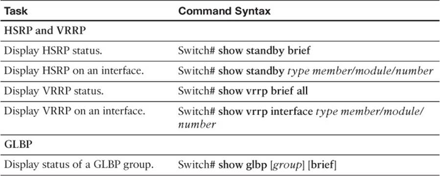
Table 18-4 Gateway Redundancy Verification Commands
Exam Preparation Tasks
Review All Key Topics
Review the most important topics in the chapter, noted with the Key Topic icon in the outer margin of the page. Table 18-5 lists a reference of these key topics and the page numbers on which each is found.
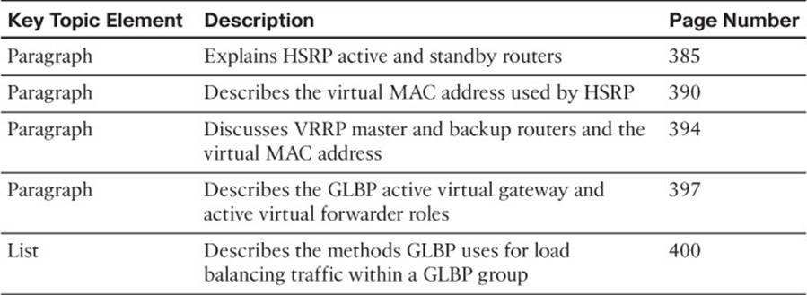
Table 18-5 Key Topics for Chapter 18
Complete Tables and Lists from Memory
Print a copy of Appendix C, “Memory Tables” (found on the CD), or at least the section for this chapter, and complete the tables and lists from memory. Appendix D, “Memory Table Answer Key,” also on the CD, includes completed tables and lists to check your work.
Define Key Terms
Define the following key terms from this chapter, and check your answers in the glossary:
HSRP active router
HSRP standby router
VRRP master router
VRRP backup router
active virtual gateway (AVG)
active virtual forwarder (AVF)
Use Command Reference to Check Your Memory
This section includes the most important configuration and EXEC commands covered in this chapter. It might not be necessary to memorize the complete syntax of every command, but you should remember the basic keywords that are needed.
To test your memory of the configuration commands presented in this chapter, cover the right side of Tables 18-6 through 18-8 with a piece of paper, read the description on the left side, and then see how much of the command you can remember.
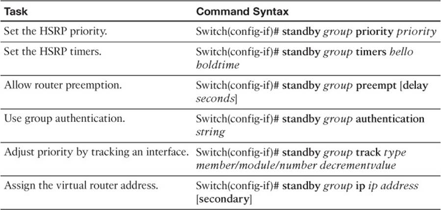
Table 18-6 HSRP Configuration Commands
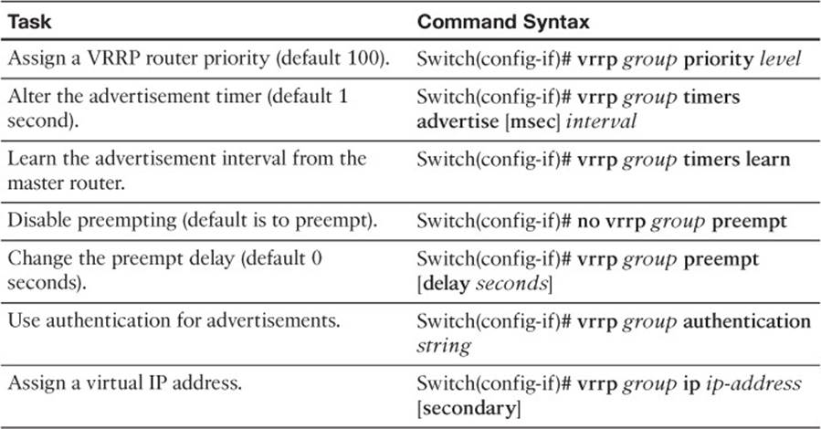
Table 18-7 VRRP Configuration Commands
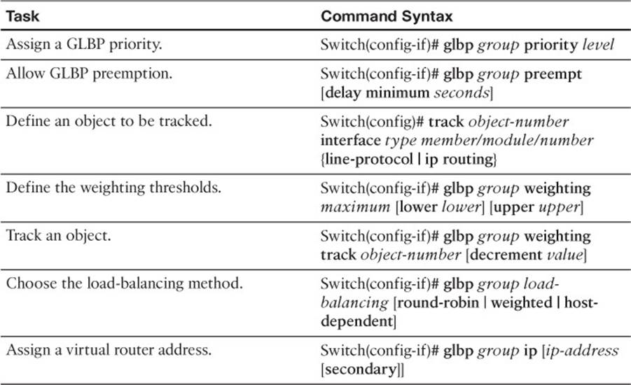
Table 18-8 GLBP Configuration Commands