CCNP Routing and Switching SWITCH 300-115 Official Cert Guide (2015)
Part VII. Securing Switched Networks
Chapter 20. Securing VLANs
This chapter covers the following topics that you need to master for the CCNP SWITCH exam:
![]() VLAN Access Lists: This section discusses how traffic can be controlled within a VLAN. You can use VLAN access control lists (ACL) to filter packets even as they are bridged or switched.
VLAN Access Lists: This section discusses how traffic can be controlled within a VLAN. You can use VLAN access control lists (ACL) to filter packets even as they are bridged or switched.
![]() Private VLANs: This section explains the mechanisms that you can use to provide isolation within a single VLAN. Private VLANs have a unidirectional nature; several of them can be isolated yet share a common subnet and gateway.
Private VLANs: This section explains the mechanisms that you can use to provide isolation within a single VLAN. Private VLANs have a unidirectional nature; several of them can be isolated yet share a common subnet and gateway.
![]() Securing VLAN Trunks: This section covers two types of attacks that can be leveraged against a VLAN trunk link. If a trunk link is extended to or accessible from an attacker, any VLAN carried over the trunk can be compromised in turn.
Securing VLAN Trunks: This section covers two types of attacks that can be leveraged against a VLAN trunk link. If a trunk link is extended to or accessible from an attacker, any VLAN carried over the trunk can be compromised in turn.
Traditionally, traffic has been filtered only at router boundaries, where packets naturally are inspected before being forwarded. This is true within Catalyst switches because access lists can be applied as a part of multilayer switching. Catalysts also can filter packets even if they stay within the same VLAN; VLAN access control lists, or VACLs, provide this capability.
Catalyst switches also have the capability to logically divide a single VLAN into multiple partitions. Each partition can be isolated from others, with all of them sharing a common IP subnet and a common gateway address. Private VLANs make it possible to offer up a single VLAN to many disparate customers or organizations without any interaction between them.
VLAN trunks are commonly used on links between switches to carry data from multiple VLANs. If the switches are all under the same administrative control, it is easy to become complacent about the security of the trunks. A few known attacks can be used to gain access to the VLANs that are carried over trunk links. Therefore, network administrators should be aware of the steps that can be taken to prevent any attacks.
“Do I Know This Already?” Quiz
The “Do I Know This Already?” quiz allows you to assess whether you should read this entire chapter thoroughly or jump to the “Exam Preparation Tasks” section. If you are in doubt based on your answers to these questions or your own assessment of your knowledge of the topics, read the entire chapter. Table 20-1 outlines the major headings in this chapter and the “Do I Know This Already?” quiz questions that go with them. You can find the answers in Appendix A, “Answers to the ‘Do I Know This Already?’ Quizzes.”
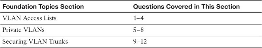
Table 20-1 “Do I Know This Already?” Foundation Topics Section-to-Question Mapping
1. Which one of the following can filter packets even if they are not routed to another Layer 3 interface?
a. IP extended access lists
b. MAC address access lists
c. VLAN access lists
d. Port-based access lists
2. In what part of a Catalyst switch are VLAN ACLs implemented?
a. NVRAM
b. CAM
c. RAM
d. TCAM
3. Which one of the following commands can implement a VLAN ACL called test?
a. access-list vlan test
b. vacl test
c. switchport vacl test
d. vlan access-map test
4. After a VACL is configured, where is it applied?
a. Globally on a VLAN
b. On the VLAN interface
c. In the VLAN configuration
d. On all ports or interfaces mapped to a VLAN
5. Which of the following private VLANs is the most restrictive?
a. Community VLAN
b. Isolated VLAN
c. Restricted VLAN
d. Promiscuous VLAN
6. The vlan 100 command has just been entered. What is the next command needed to configure VLAN 100 as a secondary isolated VLAN?
a. private-vlan isolated
b. private-vlan isolated 100
c. pvlan secondary isolated
d. No further configuration necessary
7. What type of port configuration should you use for private VLAN interfaces that connect to a router?
a. Host
b. Gateway
c. Promiscuous
d. Transparent
8. Promiscuous ports must be ______________ to primary and secondary VLANs, and host ports must be ________________.
a. Mapped, associated
b. Mapped, mapped
c. Associated, mapped
d. Associated, associated
9. In a switch spoofing attack, an attacker makes use of which one of the following?
a. The switch management IP address
b. CDP message exchanges
c. Spanning Tree Protocol
d. DTP to negotiate a trunk
10. Which one of the following commands enables you to prevent a switch spoofing attack on an end-user port?
a. switchport mode access
b. switchport mode trunk
c. no switchport spoof
d. spanning-tree spoof-guard
11. Which one of the following represents the spoofed information an attacker sends in a VLAN hopping attack?
a. 802.1Q tags
b. DTP information
c. VTP information
d. 802.1x information
12. Which one of the following methods can be used to prevent a VLAN hopping attack?
a. Use VTP throughout the network.
b. Set the native VLAN to the user access VLAN.
c. Remove the native VLAN from a trunk link.
d. Avoid using EtherChannel link bundling.
Foundation Topics
VLAN Access Lists
Access lists can manage or control traffic as it passes through a switch. When normal access lists are configured on a Catalyst switch, they filter traffic through the use of the ternary content-addressable memory (TCAM). Recall from Chapter 2, “Switch Operation,” that access lists (also known as router access lists, or RACLs) are merged or compiled into the TCAM. Each ACL is applied to an interface according to the direction of traffic—inbound or outbound. Packets then can be filtered in hardware with no switching performance penalty. However, only packets that passbetween VLANs can be filtered this way.
Packets that stay in the same VLAN do not cross a VLAN or interface boundary and do not necessarily have a direction in relation to an interface. These packets also might be non-IP or completely bridged; therefore, they never pass through the multilayer switching mechanism. VLAN access lists (VACLs) are filters that directly can affect how packets are handled within a VLAN.
VACLs are somewhat different from RACLs or traditional access control lists. Although they, too, are merged into the TCAM, they can permit, deny, or redirect packets as they are matched. VACLs also are configured in a route map fashion, with a series of matching conditions and actions to take.
VACL Configuration

VACLs are configured as a VLAN access map in much the same format as a route map. A VLAN access map consists of one or more statements, each having a common map name. First, you define the VACL with the following global configuration command:
Switch(config)# vlan access-map map-name [sequence-number]
Access map statements are evaluated in sequence according to the sequence number. Each statement can contain one or more matching conditions, followed by an action.
Next, define the matching conditions that identify the traffic to be filtered. Matching is performed by access lists (IP or MAC address ACLs), which you must configure independently. Configure a matching condition with one of the following access map configuration commands:
Switch(config-access-map)# match ip address {acl-number | acl-name}
Switch(config-access-map)# match mac address acl-name
You can repeat these commands to define several matching conditions; the first match encountered triggers an action to take. Define the action with the following access map configuration command:
Switch(config-access-map)# action {drop | forward [capture] | redirect type mod/
num}
A VACL can either drop a matching packet, forward it, or redirect it to another interface. The TCAM performs the entire VACL match and action as packets are switched or bridged within a VLAN or routed into or out of a VLAN.
Finally, you must apply the VACL to a VLAN using the following global configuration command:
Switch(config)# vlan filter map-name vlan-list vlan-list
Notice that the VACL is applied globally to one or more VLANs listed and not to a VLAN interface switch virtual interface (SVI). Recall that VLANs can be present in a switch as explicit interfaces or as inherent Layer 2 entities. The VLAN interface is the point where packets enter or leave a VLAN, so it does not make sense to apply a VACL there. Instead, the VACL needs to function within the VLAN itself, where there is no inbound or outbound direction.
For example, suppose that you need to filter traffic within VLAN 99 so that host 192.168.99.17 is not allowed to contact any other host on its local subnet. Access list local-17 is created to identify traffic between this host and anything else on its local subnet. Then a VLAN access map is defined: If the local-17 access list matches (permits) the IP address, the packet is dropped; otherwise, the packet is forwarded. Example 20-1 shows the commands necessary for this example.
Example 20-1 Filtering Traffic Within the Local Subnet
Switch(config)# ip access-list extended local-17
Switch(config-acl)# permit ip host 192.168.99.17 192.168.99.0 0.0.0.255
Switch(config-acl)# exit
Switch(config)# vlan access-map block-17 10
Switch(config-access-map)# match ip address local-17
Switch(config-access-map)# action drop
Switch(config-access-map)# vlan access-map block-17 20
Switch(config-access-map)# action forward
Switch(config-access-map)# exit
Switch(config)# vlan filter block-17 vlan-list 99
Private VLANs
Normally, traffic is allowed to move unrestricted within a VLAN. Packets sent from one host to another normally are heard only by the destination host because of the nature of Layer 2 switching.
However, if one host broadcasts a packet, all hosts on the VLAN must listen. You can use a VACL to filter packets between a source and destination in a VLAN if both connect to the local switch.
Sometimes it would be nice to have the capability to segment traffic within a single VLAN, without having to use multiple VLANs and a router. For example, in a single-VLAN server farm, all servers should be capable of communicating with the router or gateway, but the servers should not have to listen to each other’s broadcast traffic. Taking this a step further, suppose that each server belongs to a separate organization. Now each server should be isolated from the others but still be capable of reaching the gateway to find clients not on the local network.
Another application is a service provider network. Here, the provider might want to use a single VLAN to connect to several customer networks. Each customer needs to be able to contact the provider’s gateway on the VLAN. Clearly, the customer sites do not need to interact with each other.
Private VLANs (PVLANs) solve this problem on Catalyst switches. In a nutshell, a normal, or primary, VLAN can be logically associated with special unidirectional, or secondary, VLANs. Hosts associated with a secondary VLAN can communicate with ports on the primary VLAN (a router, for example), but not with another secondary VLAN. A secondary VLAN is configured as one of the following types:
![]() Isolated: Any switch ports associated with an isolated VLAN can reach the primary VLAN but not any other secondary VLAN. In addition, hosts associated with the same isolated VLAN cannot reach each other. They are, in effect, isolated from everything except the primary VLAN.
Isolated: Any switch ports associated with an isolated VLAN can reach the primary VLAN but not any other secondary VLAN. In addition, hosts associated with the same isolated VLAN cannot reach each other. They are, in effect, isolated from everything except the primary VLAN.
![]() Community: Any switch ports associated with a common community VLAN can communicate with each other and with the primary VLAN but not with any other secondary VLAN. This provides the basis for server farms and workgroups within an organization, while giving isolation between organizations.
Community: Any switch ports associated with a common community VLAN can communicate with each other and with the primary VLAN but not with any other secondary VLAN. This provides the basis for server farms and workgroups within an organization, while giving isolation between organizations.
All secondary VLANs must be associated with one primary VLAN to set up the unidirectional relationship. Private VLANs are configured using special cases of regular VLANs. However, the VLAN Trunking Protocol (VTP) does not pass any information about the private VLAN configuration. Therefore, private VLANs are only locally significant to a switch. Each of the private VLANs must be configured locally on each switch that interconnects them.
You must configure each physical switch port that uses a private VLAN with a VLAN association. You also must define the port with one of the following modes:
![]() Promiscuous: The switch port connects to a router, firewall, or other common gateway device. This port can communicate with anything else connected to the primary or any secondary VLAN. In other words, the port is in promiscuous mode, in which the rules of private VLANs are ignored.
Promiscuous: The switch port connects to a router, firewall, or other common gateway device. This port can communicate with anything else connected to the primary or any secondary VLAN. In other words, the port is in promiscuous mode, in which the rules of private VLANs are ignored.
![]() Host: The switch port connects to a regular host that resides on an isolated or community VLAN. The port communicates only with a promiscuous port or ports on the same community VLAN.
Host: The switch port connects to a regular host that resides on an isolated or community VLAN. The port communicates only with a promiscuous port or ports on the same community VLAN.
Figure 20-1 shows the basic private VLAN operation. Some host PCs connect to a secondary community VLAN. The two community VLANs associate with a primary VLAN, where the router connects. The router connects to a promiscuous port on the primary VLAN. A single host PC connects to a secondary isolated VLAN, so it can communicate only with the router’s promiscuous port.
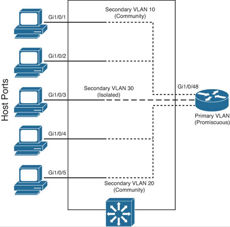
Figure 20-1 Private VLAN Functionality Within a Switch
Private VLAN Configuration
Defining a private VLAN involves several configuration steps. These steps are described in the sections that follow.
Configure the Private VLANs
To configure a private VLAN, begin by defining any secondary VLANs that are needed for isolation using the following configuration commands:
Switch(config)# vlan vlan-id
Switch(config-vlan)# private-vlan {isolated | community}
The secondary VLAN can be an isolated VLAN (no connectivity between isolated ports) or a community VLAN (connectivity between member ports).
Now define the primary VLAN that will provide the underlying private VLAN connectivity using the following configuration commands:
Switch(config)# vlan vlan-id
Switch(config-vlan)# private-vlan primary
Switch(config-vlan)# private-vlan association {secondary-vlan-list | add secondary-vlan-list | remove second
ary-vlan-list}
Be sure to associate the primary VLAN with all its component secondary VLANs using the association keyword. If the primary VLAN already has been configured, you can add (add) or remove (remove) secondary VLAN associations individually.
These VLAN configuration commands set up only the mechanisms for unidirectional connectivity from the secondary VLANs to the primary VLAN. You also must associate the individual switch ports with their respective private VLANs.
Associate Ports with Private VLANs
First, define the function of the port that will participate on a private VLAN using the following configuration command:
Switch(config-if)# switchport mode private-vlan {host | promiscuous}
If the host connected to this port is a router, firewall, or common gateway for the VLAN, use the promiscuous keyword. This allows the host to reach all other promiscuous, isolated, or community ports associated with the primary VLAN. Otherwise, any isolated or community port must receive the host keyword.
For a nonpromiscuous port (using the switchport mode private-vlan host command), you must associate the switch port with the appropriate primary and secondary VLANs. Remember, only the private VLANs themselves have been configured until now. The switch port must know how to interact with the various VLANs using the following interface configuration command:
Switch(config-if)# switchport private-vlan host-association primary-vlan-id
secondary-vlan-id
Note
When a switch port is associated with private VLANs, you do not have to configure a static access VLAN. Instead, the port takes on membership in the primary and secondary VLANs simultaneously. This does not mean that the port has a fully functional assignment to multiple VLANs. Instead, it takes on only the unidirectional behavior between the secondary and primary VLANs.
For a promiscuous port (using the switchport mode private-vlan promiscuous command), you must map the port to primary and secondary VLANs. Notice that promiscuous mode ports, or ports that can communicate with any other private VLAN device, are mapped, whereas other secondary VLAN ports are associated. One (promiscuous mode port) exhibits bidirectional behavior, whereas the other (secondary VLAN ports) exhibits unidirectional or logical behavior.
Use the following interface configuration command to map promiscuous mode ports to primary and secondary VLANs:
Switch(config-if)# switchport private-vlan mapping primary-vlan-id secondary-vlan-list | {add secondary-vlan-
list} | {remove secondary-vlan-list}
Assume, for example, that the switch in Figure 20-1 is configured as in Example 20-2. Host PCs on ports Gigabit Ethernet 1/0/1 and 1/0/2 are in community VLAN 10, hosts on ports Gigabit Ethernet 1/0/4 and 1/0/5 are in community VLAN 20, and the host on port Gigabit Ethernet 1/0/3 is in isolated VLAN 30. The router on port Gigabit Ethernet 1/0/48 is in promiscuous mode on primary VLAN 100. Each VLAN is assigned a role, and the primary VLAN is associated with its secondary VLANs. Then each interface is associated with a primary and secondary VLAN (if a host is attached) or mapped to the primary and secondary VLANs (if a promiscuous host is attached).
Example 20-2 Configuring Ports with PVLANs
Switch(config)# vlan 10
Switch(config-vlan)# private-vlan community
Switch(config-vlan)# vlan 20
Switch(config-vlan)# private-vlan community
Switch(config-vlan)# vlan 30
Switch(config-vlan)# private-vlan isolated
Switch(config-vlan)# vlan 100
Switch(config-vlan)# private-vlan primary
Switch(config-vlan)# private-vlan association 10,20,30
Switch(config-vlan)# exit
Switch(config)# interface range gigabitethernet 1/0/1 - 1/0/2
Switch(config-if)# switchport mode private-vlan host
Switch(config-if)# switchport private-vlan host-association 100 10
Switch(config-if)# exit
Switch(config)# interface range gigabitethernet 1/0/4 - 1/0/5
Switch(config-if)# switchport mode private-vlan host
Switch(config-if)# switchport private-vlan host-association 100 20
Switch(config-if)# exit
Switch(config)# interface gigabitethernet 1/0/3
Switch(config-if)# switchport mode private-vlan host
Switch(config-if)# switchport private-vlan host-association 100 30
Switch(config-if)# exit
Switch(config)# interface gigabitethernet 1/0/48
Switch(config-if)# switchport mode private-vlan promiscuous
Switch(config-if)# switchport private-vlan mapping 100 10,20,30
Associate Secondary VLANs to a Primary VLAN SVI
On switched virtual interfaces, or VLAN interfaces configured with Layer 3 addresses, you must configure some additional private VLAN mapping. Consider a different example, where the SVI for the primary VLAN, VLAN 200, has an IP address and participates in routing traffic. Secondary VLANs 40 (an isolated VLAN) and 50 (a community VLAN) are associated at Layer 2 with primary VLAN 200 using the configuration in Example 20-3.
Example 20-3 Associating Secondary VLANs to a Primary VLAN SVI
Switch(config)# vlan 40
Switch(config-vlan)# private-vlan isolated
Switch(config-vlan)# vlan 50
Switch(config-vlan)# private-vlan community
Switch(config-vlan)# vlan 200
Switch(config-vlan)# private-vlan primary
Switch(config-vlan)# private-vlan association 40,50
Switch(config-vlan)# exit
Switch(config)# interface vlan 200
Switch(config-if)# ip address 192.168.199.1 255.255.255.0
Primary VLAN 200 can forward traffic at Layer 3, but the secondary VLAN associations with it are good at only Layer 2. To allow Layer 3 traffic switching coming from the secondary VLANs as well, you must add a private VLAN mapping to the primary VLAN (SVI) interface, using the following interface configuration command:
Switch(config-if)# private-vlan mapping {secondary-vlan-list | add secondary-vlan-
list | remove secondary-vlan-list}
The primary VLAN SVI function is extended to the secondary VLANs instead of requiring SVIs for each of them. If some mapping already has been configured for the primary VLAN SVI, you can add (add) or remove (remove) secondary VLAN mappings individually.
Continuing with Example 20-3, you would map the private VLAN by adding the following commands:
Switch(config)# interface vlan 200
Switch(config-if)# private-vlan mapping 40,50
Securing VLAN Trunks
Because trunk links usually are bounded between two switches, you might think that they are more or less secure. Each end of the trunk is connected to a device that is under your control, VLANs carried over the trunk remain isolated, and so on.
Some attacks or exploits can be leveraged to gain access to a trunk or to the VLANs carried over a trunk. Therefore, you should become familiar with how the attacks work and what steps you can take to prevent them in the first place.
Switch Spoofing
Recall from Chapter 4, “VLANs and Trunks,” that two switches can be connected by a common trunk link that can carry traffic from multiple VLANs. The trunk does not have to exist all the time. The switches dynamically can negotiate its use and its encapsulation mode by exchanging Dynamic Trunking Protocol (DTP) messages.
Although DTP can make switch administration easier, it also can expose switch ports to be compromised. Suppose that a switch port is left to its default configuration, in which the trunking mode is auto. Normally, the switch port would wait to be asked by another switch in the auto or on mode to become a trunk.
Now suppose that an end user’s PC is connected to that port. A well-behaved end user would not use DTP at all, so the port would come up in access mode with a single-access VLAN. A malicious user, however, might exploit the use of DTP and attempt to negotiate a trunk with the switch port. This makes the PC appear to be another switch; in effect, the PC is spoofing a switch.
After the trunk is negotiated, the attacker has access to any VLAN that is permitted to pass over the trunk. If the switch port has been left to its default configuration, all VLANs configured on the switch are allowed onto the trunk. Figure 20-2 shows this scenario. The attacker can receive any traffic being sent over the trunk on any VLAN. In addition, he can send traffic into any VLAN of his choice.
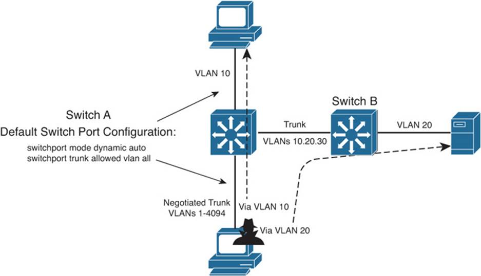
Figure 20-2 An Example of Switch Spoofing to Gain Access to a Trunk
To demonstrate this further, consider the output in Example 20-4, which shows the default access switch port configuration. Notice that trunking is possible because the port is set to dynamic auto mode, awaiting DTP negotiation from a connected device. If a trunk is negotiated, all VLANs are permitted to be carried over it.
Example 20-4 Displaying the Default Switch Port Configuration
Switch# show interfaces gigabitethernet 1/0/46 switchport
Name: Gi1/0/46
Switchport: Enabled
Administrative Mode: dynamic auto
Operational Mode: trunk
Administrative Trunking Encapsulation: negotiate
Negotiation of Trunking: On
Access Mode VLAN: 1 (default)
Trunking Native Mode VLAN: 1 (default)
Administrative Native VLAN tagging: enabled
Voice VLAN: none
Administrative private-vlan host-association: none
Administrative private-vlan mapping: none
Administrative private-vlan trunk native VLAN: none
Administrative private-vlan trunk Native VLAN tagging: enabled
Administrative private-vlan trunk encapsulation: dot1q
Administrative private-vlan trunk normal VLANs: none
Administrative private-vlan trunk private VLANs: none
Operational private-vlan: none
Trunking VLANs Enabled: ALL
Pruning VLANs Enabled: 2-1001
Capture Mode Disabled Capture VLANs Allowed: ALL
Protected: false
Unknown unicast blocked: disabled
Unknown multicast blocked: disabled
Appliance trust: none
Switch#
The solution to this situation is to configure every switch port to have an expected and controlled behavior. For example, instead of leaving an end-user switch port set to use DTP in auto mode, configure it to static access mode with the following commands:
Switch(config)# interface type member/mod/num
Switch(config-if)# switchport access vlan vlan-id
Switch(config-if)# switchport mode access
This way, an end user never will be able to send any type of spoofed traffic that will make the switch port begin trunking.
In addition, you might be wise to disable any unused switch ports to prevent someone from discovering a live port that might be exploited.
VLAN Hopping
When securing VLAN trunks, also consider the potential for an exploit called VLAN hopping. Here, an attacker positioned on one access VLAN can craft and send frames with spoofed 802.1Q tags so that the packet payloads ultimately appear on a totally different VLAN, all without the use of a router.
For this exploit to work, the following conditions must exist in the network configuration:
![]() The attacker is connected to an access switch port.
The attacker is connected to an access switch port.
![]() The same switch must have an 802.1Q trunk.
The same switch must have an 802.1Q trunk.
![]() The trunk must have the attacker’s access VLAN as its native VLAN.
The trunk must have the attacker’s access VLAN as its native VLAN.
Figure 20-3 shows how VLAN hopping works. The attacker, situated on VLAN 10, sends frames that are doubly tagged as if an 802.1Q trunk were being used. Naturally, the attacker is not connected to a trunk; he is spoofing the trunk encapsulation to trick the switch into making the frames hop over to another VLAN.
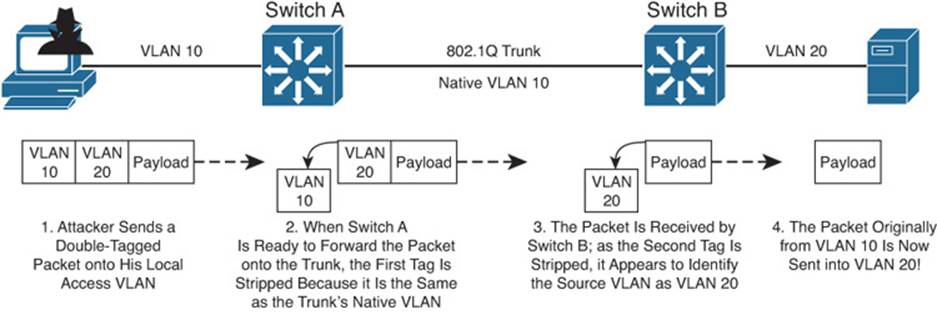
Figure 20-3 VLAN Hopping Attack Process
The regular frame—or malicious payload, in this case—is first given an 802.1Q tag with the VLAN ID of the target VLAN. Then a second bogus 802.1Q tag is added with the attacker’s access VLAN ID.
When the local switch Switch A receives a doubly tagged frame, it decides to forward it out the trunk interface. Because the first (outermost) tag has the same VLAN ID as the trunk’s native VLAN, that tag is removed as the frame is sent on the trunk. The switch believes that the native VLAN should be untagged, as it should. Now the second (innermost) tag is exposed on the trunk.
When Switch B receives the frame, it examines any 802.1Q tag it finds. The spoofed tag for VLAN 20 is found, so the tag is removed and the frame is forwarded onto VLAN 20. Now the attacker successfully has sent a frame on VLAN 10 and gotten the frame injected onto VLAN 20—all through Layer 2 switching.
Clearly, the key to this type of attack revolves around the use of untagged native VLANs. Therefore, to thwart VLAN hopping, you always should carefully configure trunk links with the following steps:
Step 1. Set the native VLAN of a trunk to a bogus or unused VLAN ID.
Step 2. Prune the native VLAN off both ends of the trunk.
For example, suppose that an 802.1Q trunk should carry only VLANs 10 and 20. You should set the native VLAN to an unused value, such as 800. Then you should remove VLAN 800 from the trunk so that it is confined to the trunk link itself. Example 20-5 demonstrates how to accomplish this.
Example 20-5 Configuring the 802.1Q Trunk to Carry Only VLANs 10 and 20
Switch(config)# vlan 800
Switch(config-vlan)# name bogus_native
Switch(config-vlan)# exit
Switch(config)# interface gigabitethernet 1/0/1
Switch(config-if)# switchport trunk encapsulation dot1q
Switch(config-if)# switchport trunk native vlan 800
Switch(config-if)# switchport trunk allowed vlan remove 800
Switch(config-if)# switchport mode trunk
Tip
Although maintenance protocols such as Cisco Discovery Protocol (CDP), Port Aggregation Protocol (PAgP), and Dynamic Trunking Protocol (DTP) normally are carried over the native VLAN of a trunk, they will not be affected if the native VLAN is removed or manually pruned from the trunk. They still will be sent and received on the native VLAN as a special case even if the native VLAN ID is not in the list of allowed VLANs.
One alternative is to force all 802.1Q trunks to add tags to frames for the native VLAN, too. The double-tagged VLAN hopping attack will not work because the switch will not remove the first tag with the native VLAN ID (VLAN 10 in the example). Instead, that tag will remain on the spoofed frame as it enters the trunk. At the far end of the trunk, the same tag will be examined, and the frame will stay on the original access VLAN (VLAN 10).
To force a switch to tag the native VLAN on all its 802.1Q trunks, you can use the following command:
Switch(config)# vlan dot1q tag native
Exam Preparation Tasks
Review All Key Topics
Review the most important topics in the chapter, noted with the Key Topic icon in the outer margin of the page. Table 20-2 lists a reference of these key topics and the page numbers on which each is found.
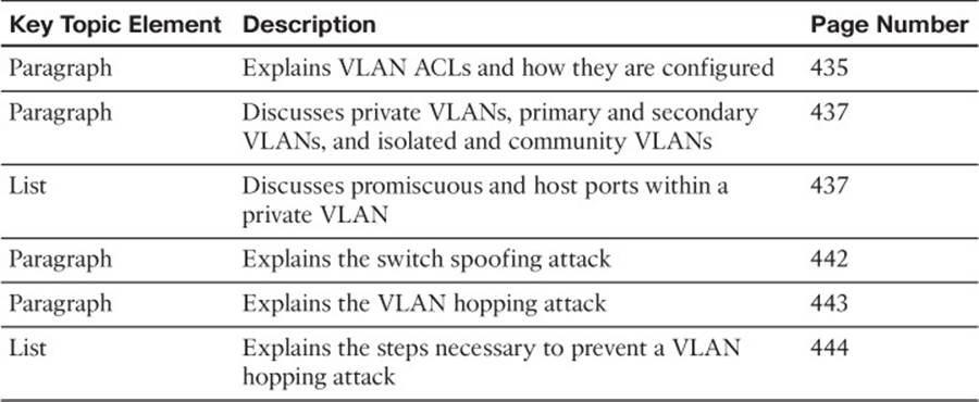
Table 20-2 Key Topics for Chapter 20
Complete Tables and Lists from Memory
There are no memory tables in this chapter.
Define Key Terms
Define the following key terms from this chapter, and check your answers in the glossary:
VACL
private VLAN
primary VLAN
secondary VLAN
isolated VLAN
community VLAN
promiscuous port
host port
switch spoofing
VLAN hopping
Use Command Reference to Check Your Memory
This section includes the most important configuration and EXEC commands covered in this chapter. It might not be necessary to memorize the complete syntax of every command, but you should remember the basic keywords that are needed.
To test your memory of the VLAN ACL and private VLAN configuration, cover the right side of Tables 20-3 and 20-4 with a piece of paper, read the description on the left side, and then see how much of the command you can remember.
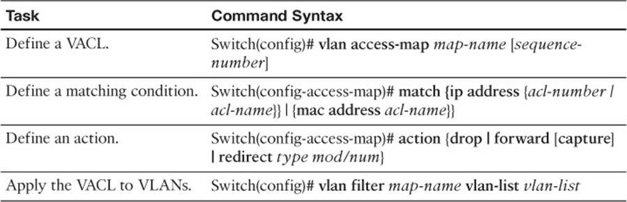
Table 20-3 VLAN ACL Configuration Commands
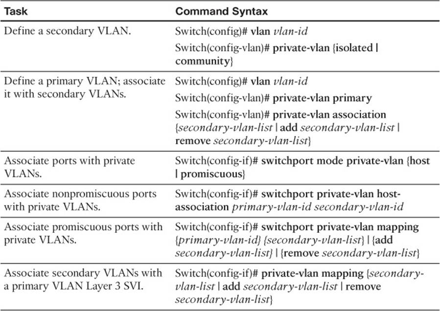
Table 20-4 Private VLAN Configuration Commands