CCNP Routing and Switching TSHOOT 300-135 Official Cert Guide (2015)
Part I. Fundamental Troubleshooting and Maintenance Concepts
Chapter 1. Introduction to Troubleshooting and Network Maintenance
This chapter covers the following topics:
![]() Introduction to Troubleshooting: This section introduces you to troubleshooting and then focuses on a structured troubleshooting approach. It also provides you with some common steps to help you be more efficient.
Introduction to Troubleshooting: This section introduces you to troubleshooting and then focuses on a structured troubleshooting approach. It also provides you with some common steps to help you be more efficient.
![]() Popular Troubleshooting Methods: This section introduces you to various troubleshooting methods that can assist in narrowing your focus during your troubleshooting efforts.
Popular Troubleshooting Methods: This section introduces you to various troubleshooting methods that can assist in narrowing your focus during your troubleshooting efforts.
![]() Introduction to Network Maintenance: This section introduces you to maintenance tasks and identifies a few well-known network maintenance models that you can adopt.
Introduction to Network Maintenance: This section introduces you to maintenance tasks and identifies a few well-known network maintenance models that you can adopt.
![]() Common Maintenance Procedures: This section reviews the common network maintenance tasks that all organizations should perform.
Common Maintenance Procedures: This section reviews the common network maintenance tasks that all organizations should perform.
![]() The Troubleshooting and Network Maintenance Relationship: This section identifies the importance of aligning maintenance tasks with troubleshooting goals.
The Troubleshooting and Network Maintenance Relationship: This section identifies the importance of aligning maintenance tasks with troubleshooting goals.
Business operations, without a doubt, depend on the reliable operation of data networks (which might also carry voice and video traffic). This statement holds true regardless of the business size. A structured and systematic maintenance approach significantly contributes to the uptime for all networks. In addition, having a sound troubleshooting methodology in place helps ensure that when issues arise you are confident and ready to fix them.
Consider a vehicle as an example. Regular maintenance such as oil changes, joint lubrication, and fluid top-offs are performed on a vehicle to ensure that problems do not arise and the life of that vehicle is maximized. However, if an issue does arise, it is taken to a mechanic so that they may troubleshoot the issue using a structured troubleshooting process and ultimately fix the vehicle. Similarly, the number of issues in a network can be reduced by following a maintenance plan, and troubleshooting can be more effective with a structured approach in place.
This chapter discusses the importance of having a structured troubleshooting approach and a solid network maintenance plan. It identifies many popular models, structures, and tasks that should be considered by all organizations. However, as you will see, there is no “one-stop shop for all your needs” when it comes to troubleshooting and network maintenance. It is more of an art that you will master over time.
“Do I Know This Already?” Quiz
The “Do I Know This Already?” quiz allows you to assess whether you should read this entire chapter thoroughly or jump to the “Exam Preparation Tasks” section. If you are in doubt about your answers to these questions or your own assessment of your knowledge of the topics, read the entire chapter. Table 1-1 lists the major headings in this chapter and their corresponding “Do I Know This Already?” quiz questions. You can find the answers in Appendix A, “Answers to the ‘Do I Know This Already?’ Quizzes.”
Table 1-1 “Do I Know This Already?” Section-to-Question Mapping
Caution
The goal of self-assessment is to gauge your mastery of the topics in this chapter. If you do not know the answer to a question or are only partially sure of the answer, you should mark that question as wrong for purposes of the self-assessment. Giving yourself credit for an answer that you correctly guess skews your self-assessment results and might provide you with a false sense of security.
1. Identify the three steps in a simplified troubleshooting model.
a. Problem replication
b. Problem diagnosis
c. Problem resolution
d. Problem report
2. Which of the following is the best statement to include in a problem report?
a. The network is broken.
b. User A cannot reach the network.
c. User B recently changed his PC’s operating system to Microsoft Windows 7.
d. User C is unable to attach to an internal share resource of \\10.1.1.1\Budget, although he can print to all network printers, and he can reach the Internet.
3. What troubleshooting step should you perform after a problem has been reported and clearly defined?
a. Propose an hypothesis
b. Collect information
c. Eliminate potential causes
d. Examine collected information
4. What are the two primary goals of troubleshooters as they are collecting information?
a. Eliminate potential causes from consideration
b. Identify indicators pointing to the underlying cause of the problem
c. Propose an hypothesis about what is most likely causing the problem
d. Find evidence that can be used to eliminate potential causes
5. When performing the “eliminate potential causes” troubleshooting step, which caution should the troubleshooter be aware of?
a. The danger of drawing an invalid conclusion from the observed data
b. The danger of troubleshooting a network component over which the troubleshooter does not have authority
c. The danger of causing disruptions in workflow by implementing the proposed solution
d. The danger of creating a new problem by implementing the proposed solution
6. A troubleshooter is hypothesizing a cause for an urgent problem, and her hypothesis involves a network device that she is not authorized to configure. The person who is authorized to configure the network device is unavailable. What should the troubleshooter do?
a. Wait for authorized personnel to address the issue.
b. Attempt to find a temporary workaround for the issue.
c. Override corporate policy, based on the urgency, and configure the network device independently because authorized personnel are not currently available.
d. Instruct the user to report the problem to the proper department that is authorized to resolve the issue.
7. Experienced troubleshooters with in-depth comprehension of a particular network might skip the examine information and eliminate potential causes steps in a structured troubleshooting model, instead relying on their own insight to determine the most likely cause of a problem. This illustrates what approach to network troubleshooting?
a. Ad hoc
b. Shoot from the hip
c. Crystal ball
d. Independent path
8. Which of the following troubleshooting models requires access to a specific application?
a. Bottom-up
b. Divide-and-conquer
c. Comparing configurations
d. Top-down
9. Based on your analysis of a problem report and the data collected, you want to use a troubleshooting model that can quickly eliminate multiple layers of the OSI model as potential sources of the reported problem. Which of the following troubleshooting methods would be most appropriate?
a. Following the traffic path
b. Bottom-up
c. Divide-and-conquer
d. Component swapping
10. Which of the following are considered network maintenance tasks? (Choose the three best answers.)
a. Troubleshooting problem reports
b. Attending training on emerging network technologies
c. Planning for network expansion
d. Hardware installation
11. Network maintenance tasks can be categorized into one of which two categories?
a. Recovery tasks
b. Interrupt-driven tasks
c. Structured tasks
d. Installation tasks
12. Which letter in the FCAPS acronym represents the maintenance area responsible for billing end users?
a. F
b. C
c. A
d. P
e. S
13. The lists of tasks required to maintain a network can vary widely, depending on the goals and characteristics of that network. However, some network maintenance tasks are common to most networks. Which of the following would be considered a common task that should be present in any network maintenance model?
a. Performing database synchronization for a network’s Microsoft Active Directory
b. Making sure that digital certificates used for PKI are renewed in advance of their expiration
c. Using Cisco Prime to dynamically discover network device changes
d. Performing scheduled backups
14. Which of the following statements is true about scheduled maintenance?
a. Scheduled maintenance helps ensure that important maintenance tasks are not overlooked.
b. Scheduled maintenance is not recommended for larger networks, because of the diversity of maintenance needs.
c. Maintenance tasks should only be performed based on a scheduled maintenance schedule, to reduce unexpected workflow interruptions.
d. Scheduled maintenance is more of a reactive approach to network maintenance, as opposed to a proactive approach.
15. Which of the following questions are appropriate when defining your change management policies?
a. What version of operating system is currently running on the device to be upgraded?
b. What is the return on investment (ROI) of an upgrade?
c. What measureable criteria determine the success or failure of a network change?
d. Who is responsible for authorizing various types of network changes?
16. Which three of the following components would you expect to find in a set of network documentation?
a. Logical topology diagram
b. Listing of interconnections
c. Copy of IOS image
d. IP address assignments
17. What is the ideal relationship between network maintenance and troubleshooting?
a. Networking maintenance and troubleshooting efforts should be isolated from one another.
b. Networking maintenance and troubleshooting efforts should complement one another.
c. Networking maintenance and troubleshooting efforts should be conducted by different personnel.
d. Networking maintenance is a subset of network troubleshooting.
18. Which three of the following suggestions can best help troubleshooters keep in mind the need to document their steps?
a. Require documentation
b. Keep documentation in a hidden folder
c. Schedule documentation checks
d. Automate documentation
19. Which three troubleshooting phases require clear communication with end users?
a. Problem report
b. Information collection
c. Hypothesis verification
d. Problem resolution
20. What are two elements of a change management system?
a. Determine when changes can be made
b. Determine potential causes for the problem requiring the change
c. Determine who can authorize a change
d. Determine what change should be made
Foundation Topics
Introduction to Troubleshooting
Troubleshooting is a skill, and like all skills, you will get better at it the more you have to perform it. The more troubleshooting situations you are placed in, the more your skills will improve, and as a result of this, the more your confidence will grow. However, don’t start wishing for issues to happen in your organization just so that you can get more experience. Although there is no right or wrong way to troubleshoot, there is definitely a more efficient and effective way to troubleshoot that all experienced troubleshooters follow. This section begins by introducing you to troubleshooting. It then focuses on a structured troubleshooting approach that provides you with some common methods to enhance your efficiency.
Defining Troubleshooting
Troubleshooting at its essence is the process of responding to a problem report (sometimes in the form of a trouble ticket), diagnosing the underlying cause of the problem, and resolving the problem. Although you normally think of the troubleshooting process as beginning when a user reports an issue, you need to understand that through effective network monitoring you may detect a situation that could become a troubleshooting issue and resolve that situation before it impacts users.
After an issue is reported, the first step toward resolution is clearly defining the issue. When you have a clearly defined troubleshooting target, you can begin gathering further information related to it. From this information, you should be able to better define the issue. Then based on your diagnosis, you can propose an hypothesis about what is most likely causing the issue. Then the evaluation of these likely causes leads to the identification of the suspected underlying root cause of the issue.
After you identify a suspected underlying cause, you next define approaches to resolving the issue and select what you consider to be the best approach. Sometimes the best approach to resolving an issue cannot be implemented immediately. For example, a piece of equipment might need replacing, or a business’s workflow might be disrupted by implementing such an approach during working hours. In such situations, a troubleshooter might use a temporary fix until a permanent fix can be put in place.
Let’s look at an example. It is 3:00 p.m. at a luxury hotel in Las Vegas. On this day, the hotel cannot register guests or create the keycards needed for guest rooms. After following the documented troubleshooting procedures, the network team discovers that Spanning Tree Protocol (STP) has failed on a Cisco Catalyst switch, resulting in a Layer 2 topological loop. Thus, the network is being flooded with traffic, preventing registrations and keycards from being completed because the server is not accessible. The network team now has to decide on the best course of action at this point. The permanent fix of replacing the failed equipment immediately would disrupt the network further and take a considerable amount of time, thus delaying the guest registrations further. A temporary fix would be to disconnect the redundant links involved in the loop so that the Layer 2 loop is broken and guests can be registered at that point. When the impact on guests and guest services is minimal, the network team can implement the permanent fix. Consider Figure 1-1, which depicts a simplified model of the troubleshooting steps previously described.
![]()
Figure 1-1 Simplified Troubleshooting Flow

This simplified model consists of three steps:
Step 1. Problem report
Step 2. Problem diagnosis
Step 3. Problem resolution
Of these three steps, most of a troubleshooter’s efforts are spent in the problem diagnosis step. For example, your child reports that the toaster won’t work. That is the problem report step. You have it clarified further, and your child indicates that the toaster does not get hot. So, you decide to take a look at the toaster and diagnose it. This is the problem diagnosis step, which is broken up into multiple subcomponents. Table 1-2 describes key components of this problem diagnosis step.
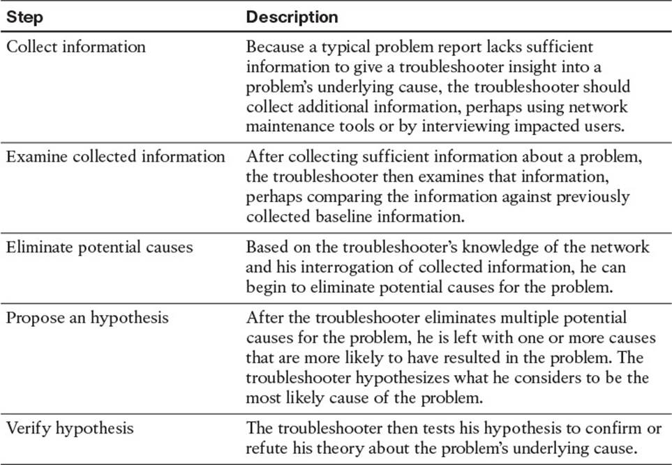
Table 1-2 Steps to Diagnose a Problem
After collecting, examining, and eliminating, you hypothesize that the power cable for the toaster is not plugged in. You test your hypothesis, and it is correct. Problem solved. This was a simple example, but even with a toaster, you spent the majority of your time diagnosing the problem. Once you determined that there was no electricity to the toaster, you had to figure out whether it was plugged in. If it was plugged in, you then had to consider whether the wall outlet was damaged, or the circuit breaker was off, or the toaster was too old and it broke. All of your effort focused on the problem diagnosis step.
By combining the three main steps with the five substeps, you get the following structured troubleshooting procedure:
Step 1. Problem report
Step 2. Collect information
Step 3. Examine collected information
Step 4. Eliminate potential causes
Step 5. Propose an hypothesis
Step 6. Verify hypothesis
Step 7. Problem resolution
The Value of Structured Troubleshooting
Troubleshooting skills vary from administrator to administrator, and as mentioned earlier, your skills as a troubleshooter will get better with experience. However, as a troubleshooter, your primary goal is to be efficient. Being fast comes with experience, but it is not worth much if you are not efficient. To be efficient, you need to follow a structured troubleshooting method. A structured troubleshooting method might look like the approach depicted in Figure 1-2.
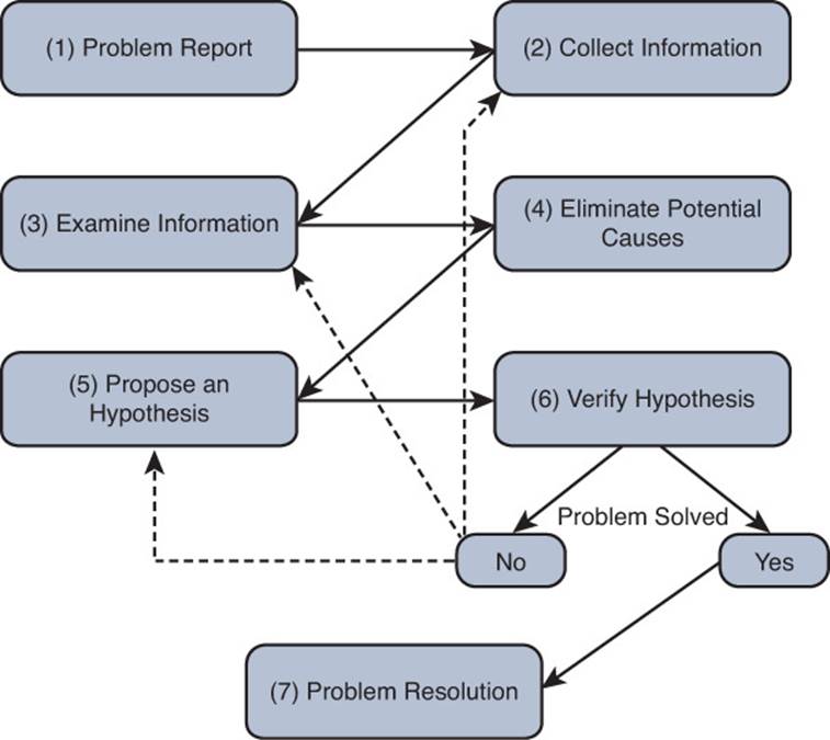
Figure 1-2 Example of a Structured Troubleshooting Approach
If you do not follow a structured approach, you might find yourself moving around troubleshooting tasks in a fairly random way based on instinct. Although in one instance you might be fast at solving the issue, in the next instance you end up taking an unacceptable amount of time. In addition, it can become confusing to remember what you have tried and what you have not. Eventually, you find yourself repeating solutions you have already tried, hoping it works. Also, if another administrator comes to assist you, communicating to that administrator the steps you have already gone through becomes a challenge. Therefore, following a structured troubleshooting approach helps you reduce the possibility of trying the same resolution more than once and inadvertently skipping a task. It also aids in communicating to someone else possibilities that you have already eliminated.
With experience, you will start to see similar issues. In addition, you should have exceptional documentation on past network issues and the steps used to solve them. In such instances, spending time methodically examining information and eliminating potential causes might actually be less efficient than immediately hypothesizing a cause after you collect information about the problem and review past documents. This method, illustrated in Figure 1-3, is often called the shoot from the hip method.
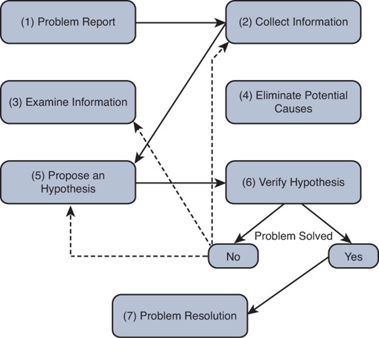
Figure 1-3 Example of a Shoot from the Hip Troubleshooting Approach
The danger with the shoot from the hip method is that if your instincts are incorrect, and the problem is not solved, you waste valuable time. Therefore, you need to be able to revert back to the structured troubleshooting approach as needed and examine all collected information.
A Structured Approach
No single collection of troubleshooting procedures is capable of addressing all conceivable network issues because there are too many variables (for example, user actions). However, having a structured troubleshooting approach helps ensure that the organization’s troubleshooting efforts are following a similar flow each time an issue arises no matter who is assigned the task. This will allow one troubleshooter to more efficiently take over for or assist another troubleshooter if required.
This section examines each step in a structured approach in more detail as shown in Figure 1-4.
Figure 1-4 A Structured Troubleshooting Approach
1. Problem Report
A problem report from a user often lacks sufficient detail for you to take that problem report and move on to the next troubleshooting process (that is, collect information). For example, a user might report, “The network is broken.” If you receive such a vague report, you probably need to contact the user and ask him exactly what aspect of the network is not functioning correctly.
After your interview with the user, you should be able to construct a more detailed problem report that includes statements such as, when the user does X, she observes Y. For example, “When the user attempts to connect to a website on the Internet, her browser reports a 404 error. However, the user can successfully navigate to websites on her company’s intranet.” Or, “When the user attempts to connect to an FTP site using a web browser, the web browser reports the page can’t be displayed.”
After you have a clear understanding of the issue, you might need to determine who is responsible for working on the hardware or software associated with that issue. For example, perhaps your organization has one IT group tasked with managing switches and another IT group charged with managing routers. Therefore, as the initial point of contact, you might need to decide whether this issue is one you are authorized to address or if you need to forward the issue to someone else who is authorized. If you are not sure at this point, start collecting information so that the picture can become clearer, and be mindful that you might have to pass this information on to another member of your IT group at some point, so accurate documentation is important.
2. Collect Information
When you are in possession of a clear problem report, the next step is gathering relevant information pertaining to the problem, as shown in Figure 1-5.
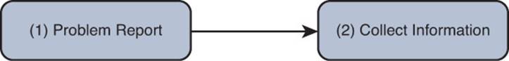
Figure 1-5 A Structured Troubleshooting Approach (Collect Information)
Efficiently and effectively gathering information involves focusing information gathering efforts on appropriate network entities (for example, routers, servers, switches, or clients) from which information should be collected. Otherwise, the troubleshooter could waste time wading through reams of irrelevant data. For example, to be efficient and effective, the troubleshooter needs to understand what is required to access the resources the end user is unable to access. With our FTP site problem report, the FTP resources are accessible through an FTP client. Troubleshooters not aware of that might spend hours collecting irrelevant data with debug, show, ping, and traceroute commands, when all they had to do was point the user to the FTP client installed on the client’s computer.
In addition, perhaps a troubleshooter is using a troubleshooting model that follows the path of the affected traffic (as discussed in the “Popular Troubleshooting Methods” section of this chapter), and information needs to be collected from a network device over which the troubleshooter has no access. At that point, the troubleshooter might need to work with appropriate personnel who have access to that device. Alternatively, the troubleshooter might switch troubleshooting models. For example, instead of following the traffic’s path, the troubleshooter might swap components or use a bottom-up troubleshooting model.
3. Examine Collected Information
After collecting information about the problem report (for example, collecting output from show or debug commands, performing packet captures, using ping, or traceroute), the next structured troubleshooting step is to analyze the collected information as shown in Figure 1-6.
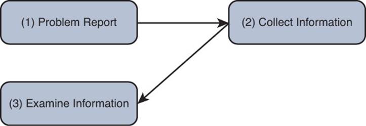
Figure 1-6 A Structured Troubleshooting Approach (Examine Information)
A troubleshooter has two primary goals while examining the collected information:
![]() Identify indicators pointing to the underlying cause of the problem
Identify indicators pointing to the underlying cause of the problem
![]() Find evidence that can be used to eliminate potential causes
Find evidence that can be used to eliminate potential causes
To achieve these two goals, the troubleshooter attempts to find a balance between two questions:
![]() What is occurring on the network?
What is occurring on the network?
![]() What should be occurring on the network?
What should be occurring on the network?
The delta between the responses to these questions might give the troubleshooter insight into the underlying cause of a reported problem. A challenge, however, is for the troubleshooter to know what currently should be occurring on the network.
If the troubleshooter is experienced with the applications and protocols being examined, the troubleshooter might be able to determine what is occurring on the network and how that differs from what should be occurring. However, if the troubleshooter lacks knowledge of specific protocol behavior, she still might be able to effectively examine the collected information by contrasting that information with baseline data or documentation.
Baseline data might contain, for example, the output of show and debug commands issued on routers when the network was functioning properly. By contrasting this baseline data with data collected after a problem occurred, even an inexperienced troubleshooter might be able to see the difference between the data sets, thus providing a clue as to the underlying cause of the problem under investigation. This implies that as part of a routine network maintenance plan, baseline data should periodically be collected when the network is functioning properly.
Documentation plays an extremely important role at this point. Accurate and up-to-date documentation can assist a troubleshooter in examining the collected data to determine whether anything has changed in relation to the setup or configuration. Going back to the FTP example, if the troubleshooter was not aware that an FTP client was required, a quick review of the documentation related to FTP connectivity would indicate so. This would allow the troubleshooter to move on to the next step.
4. Eliminate Potential Causes
Following an examination of collected data, a troubleshooter can start to form conclusions based on that data. Some conclusions might suggest a potential cause for the problem, whereas other conclusions eliminate certain causes from consideration (see Figure 1-7).
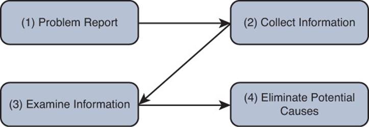
Figure 1-7 A Structured Troubleshooting Approach (Eliminate Potential Causes)
It is imperative that you not jump to conclusions at this point. Jumping to conclusions can make you less efficient as a troubleshooter as you start formulating hypotheses based on a small fraction of collected data, which leads to more work and slower overall response times to problems. As an example, a troubleshooter might jump to a conclusion based on the following scenario, which results in wasted time:
A problem report indicates that PC A cannot communicate with server A, as shown in Figure 1-8. The troubleshooter is using a troubleshooting method that follows the path of traffic through the network. The troubleshooter examines output from the show cdp neighbor command on routers R1 and R2. Because those routers do not recognize each other as Cisco Discovery Protocol (CDP) neighbors, the troubleshooter leaps to the conclusion that Layer 2 and Layer 1 connectivity is down between R1 and R2. The troubleshooter then runs to the physical routers to verify physical connectivity, only to see that all is fine. Reviewing further output and documentation indicates that CDP is disabled on R1 and R2 interfaces for security reasons. Therefore, the output of show cdp neighbors alone is insufficient to conclude that Layer 2 and 1 connectivity was the problem.

Figure 1-8 Scenario Topology
On another note, a caution to be observed when drawing conclusions is not to read more into the data than what is actually there. As an example, a troubleshooter might reach a faulty conclusion based on the following scenario:
A problem report indicates that PC A cannot communicate with server A, as shown in Figure 1-8. The troubleshooter is using a troubleshooting method that follows the path of traffic through the network. The troubleshooter examines output from the show cdp neighbor command on routers R1 and R2. Because those routers recognize each other as Cisco Discovery Protocol (CDP) neighbors, the troubleshooter leaps to the conclusion that these two routers see each other as Open Shortest Path First (OSPF) neighbors and have mutually formed OSPF adjacencies. However, the show cdp neighbor output is insufficient to conclude that OSPF adjacencies have been formed between routers R1 and R2.
In addition, if time permits, explaining the rationale for your conclusions to a coworker can often help reveal faulty conclusions. As shown by the previous examples, continuing your troubleshooting efforts based on a faulty conclusion can dramatically increase the time required to resolve a problem.
5. Propose an Hypothesis
By eliminating potential causes of a reported problem, as described in the previous process, troubleshooters should be left with one or a few potential causes that they can focus on. At this point, troubleshooters should rank the potential causes from most likely to least likely. Troubleshooters should then focus on the cause they believe is most likely to be the underlying one for the reported problem and propose an hypothesis, as shown in Figure 1-9.
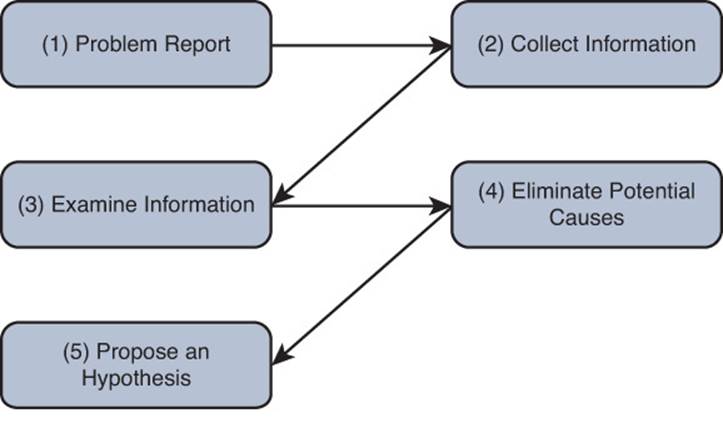
Figure 1-9 A Structured Troubleshooting Approach (Propose an Hypothesis)
After proposing an hypothesis, troubleshooters might realize that they are not authorized to access a network device that needs to be accessed to resolve the problem report. In such a situation, a troubleshooter needs to assess whether the problem can wait until authorized personnel have an opportunity to resolve the issue. If the problem is urgent and no authorized administrator is currently available, the troubleshooter might attempt to at least alleviate the symptoms of the problem by creating a temporary workaround. Although this approach does not solve the underlying cause, it might help business operations continue until the main cause of the problem can be appropriately addressed.
6. Verify Hypothesis
After troubleshooters propose what they believe to be the most likely cause of a problem, they need to develop a plan to address the suspected cause and implement it. Alternatively, if troubleshooters decide to implement a workaround, they need to come up with a plan and implement it while noting that a permanent solution is still needed. However, implementing a plan that resolves a network issue often causes temporary network outages for other users or services. Therefore, the troubleshooter must balance the urgency of the problem with the potential overall loss of productivity, which ultimately affects the financial bottom line. There should be a change management procedure in place that helps the troubleshooter determine the most appropriate time to make changes to the production network and the steps required to do so. If the impact on workflow outweighs the urgency of the problem, the troubleshooter might wait until after business hours to execute the plan.
A key (and you should make it mandatory) component in implementing a problem solution is to have the steps documented. Not only does a documented list of steps help ensure the troubleshooter does not skip any, but such a document can serve as a rollback plan if the implemented solution fails to resolve the problem. Therefore, if the problem is not resolved after the troubleshooter implements the plan, or if the execution of the plan resulted in one or more additional problems, the troubleshooter should execute the rollback plan. After the network is returned to its previous state (that is, the state prior to deploying the proposed solution); the troubleshooter can then reevaluate her hypothesis.
Although the troubleshooter might have successfully identified the underlying cause, perhaps the solution failed to resolve that cause. In that case, the troubleshooter could create a different plan to address that cause. Alternatively, if the troubleshooter had identified other causes and ranked them during the propose an hypothesis step, she can focus her attention on the next most likely cause and create an action plan to resolve that cause and implement it.
This process can be repeated until the troubleshooter has exhausted the list of potential causes or is unable to collect information that can point to other causes, as shown in Figure 1-10. At that point, a troubleshooter might need to gather additional information or enlist the aid of a coworker or the Cisco Technical Assistance Center (TAC).
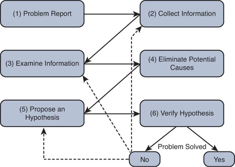
Figure 1-10 A Structured Troubleshooting Approach (Verify Hypothesis)
7. Problem Resolution
This is the final step of the structured approach, as shown in Figure 1-11. Although this is one of the most important steps, it is often forgotten or overlooked. After the reported problem is resolved, the troubleshooter should make sure that the solution becomes a documented part of the network. This implies that routine network maintenance will maintain the implemented solution. For example, if the solution involves reconfiguring a Cisco IOS router, a backup of that new configuration should be made part of routine network maintenance practices.
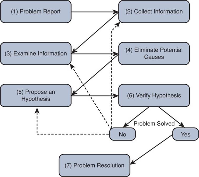
Figure 1-11 A Structured Troubleshooting Approach (Problem Resolution)
As a final task, the troubleshooter should report the problem resolution to the appropriate party or parties. Beyond simply notifying a user that a problem has been resolved, the troubleshooter should get user confirmation that the observed symptoms are now gone. This task confirms that the troubleshooter resolved the specific issue reported in the problem report, rather than a tangential issue.
Popular Troubleshooting Methods
As shown in the structured approach, the elimination of potential causes is a key step. You can use several common troubleshooting methods to narrow the field of potential causes:

![]() The top-down method
The top-down method
![]() The bottom-up method
The bottom-up method
![]() The divide-and-conquer method
The divide-and-conquer method
![]() Following the traffic path
Following the traffic path
![]() Comparing configurations
Comparing configurations
![]() Component Swapping
Component Swapping
This section defines each of these methods in greater detail. However, keep in mind that there is no single best method. Depending on your situation and the issue you are troubleshooting, you may use one or multiple methods.
The Top-Down Method
The top-down troubleshooting method begins at the top layer of the Open Systems Interconnection (OSI) seven-layer model, as shown in Figure 1-12. The top layer is numbered Layer 7 and is named the application layer.
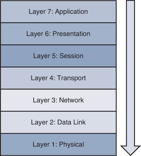
Figure 1-12 Top-Down Troubleshooting Method
The top-down method first checks the application residing at the application layer and moves down from there. The theory is, when the troubleshooter encounters a layer that is functioning, the assumption can be made that all lower layers are also functioning. For example, if you can ping a remote IP address, because ping uses Internet Control Message Protocol (ICMP), which is a Layer 3 protocol, you can assume that Layers 1–3 are functioning properly. Otherwise, your ping would have failed. A potential downside to this approach is that the troubleshooter needs access to the specific application experiencing a problem to test Layer 7.
The Bottom-Up Method
The reciprocal of the top-down method is the bottom-up method, as illustrated in Figure 1-13. The bottom-up method seeks to narrow the field of potential causes by eliminating OSI layers beginning at Layer 1, the physical layer.
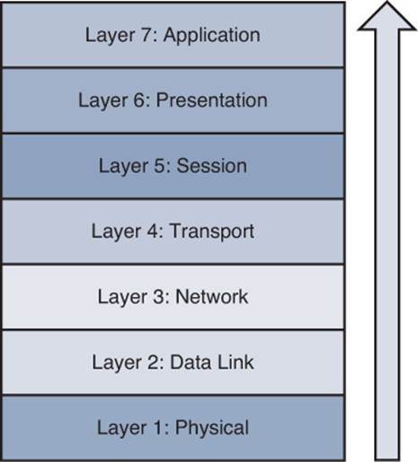
Figure 1-13 Bottom-Up Troubleshooting Method
Although this is a highly effective method, the bottom-up approach might not be efficient in larger networks because of the time required to fully test lower layers of the OSI model. Therefore, the bottom-up method is often used after employing some other method to narrow the scope of the problem.
The Divide-and-Conquer Method
After analyzing the information collected for a problem, you might not see a clear indication as to whether the top-down or bottom-up approach would be most effective. In such a situation, you might select the divide-and-conquer approach, which begins in the middle of the OSI stack, as shown in Figure 1-14.
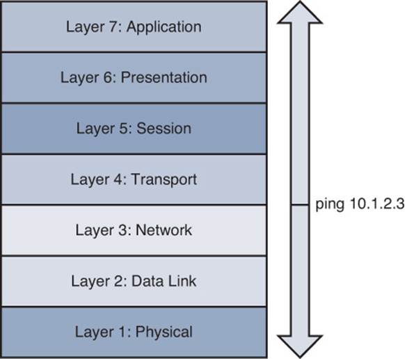
Figure 1-14 Divide-and-Conquer Troubleshooting Method
In Figure 1-14, the network administrator issued the ping 10.1.2.3 command. If the result was successful, the administrator could conclude that Layers 1–3 were operational, and a bottom-up approach could begin from that point. However, if the ping failed, the administrator could begin a top-down approach at Layer 3.
The Following the Traffic Path Method
Another useful troubleshooting approach is to follow the path of the traffic experiencing a problem. For example, if the client depicted in Figure 1-15 is unable to reach its server, you could first check the link between the client and switch SW1. If everything looks good on that link, you could then check the connection between the switch SW1 and router R1. Next, you would check the link between router R1 and switch SW2, and finally the link between switch SW2 and the server.
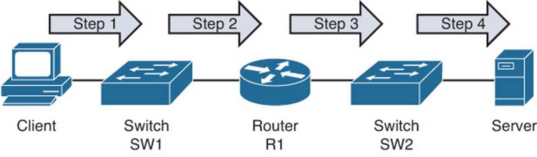
Figure 1-15 Following the Traffic Path Troubleshooting Method
The Comparing Configurations Method
Did you ever find yourself looking through a Highlights magazine as a child? This magazine often featured two similar pictures, and you were asked to spot the differences. This childhood skill can also prove valuable when troubleshooting some network issues. For example, imagine that you have multiple remote offices, each running the same model of Cisco router. Clients at one of those remote offices cannot obtain an IP address via Dynamic Host Configuration Protocol (DHCP). One troubleshooting approach is to compare that site’s router configuration with the router configuration of another remote site that is working properly. You can also look at the configuration stored in a document (Word, Notepad) to see whether it is the same. This methodology is often an appropriate approach for a less-experienced troubleshooter not well versed in the specifics of the network. However, the problem might be resolved without a thorough understanding of what caused the problem. Therefore, the problem is more likely to recur. In addition, what if the documentation is outdated? Now, in addition to the original issue, there are additional issues introduced based on an invalid configuration.
Can you spot the difference in the outputs of Example 1-1a and Example 1-1b?
Example 1-1a show run
R1#show run
...OUTPUT OMITTED...
ip dhcp excluded-address 10.8.8.1 10.8.8.10
!
ip dhcp pool POOL-A
network 10.8.8.0 255.255.255.0
default-router 10.8.8.11
dns-server 192.168.1.1
netbios-name-server 192.168.1.2
...OUTPUT OMITTED...
Example 1-1b more tftp://10.1.1.10/R1.cfg
R1#more tftp://10.1.1.10/R1.cfg
...OUTPUT OMITTED...
ip dhcp excluded-address 10.8.8.1 10.8.8.10
!
ip dhcp pool POOL-A
network 10.8.8.0 255.255.255.0
default-router 10.8.8.1
dns-server 192.168.1.1
netbios-name-server 192.168.1.2
...OUTPUT OMITTED...
In Example 1-1a, show run is displaying the current running configuration. Example 1-1b has the more tftp://10.1.1.10/R1.cfg output displaying the archived configuration that was produced as a baseline and stored on a TFTP server. The default router has been changed from 10.8.8.1 to 10.8.8.11.
The Component Swapping Method
Yet another approach to narrowing the field of potential causes of a problem is to physically swap out components. If a problem’s symptoms disappear after swapping out a particular component (for example, a cable or a switch), you can conclude that the old component was faulty (either in its hardware or its configuration).
As an example, consider Figure 1-16. A problem report states that the connection between laptop A and switch SW1 is not bringing up a link light on either the laptop or the switch.
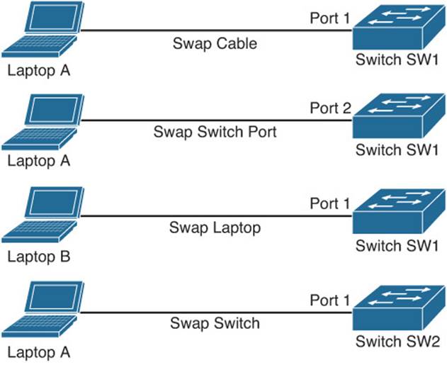
Figure 1-16 Component Swapping
As a first step, you might swap out the cable interconnecting these two devices with a known working cable.
If the problem persists, you will want to undo the change you made and then move the cable from switchport 1 to switchport 2. As a next step, you could connect a different laptop to switch SW1. If the problem goes away, you could conclude that the issue is with laptop A. However, if the problem continues, you could swap out switch SW1 with another switch (SW2 in this example). As you test each component and find it is not the problem, undo the change.
Although swapping out components in this fashion might not provide great insight into the specific problem, it could help focus your troubleshooting efforts. For example, if swapping out the switch resolved the issue, you could start to investigate the configuration of the original switch, checking for configuration or hardware issues.
Practice Exercise: Selecting a Troubleshooting Approach
As a troubleshooter, you might use one of the previously discussed troubleshooting methods or perhaps a combination of methods to eliminate causes. To illustrate how you might select an appropriate troubleshooting approach, consider the following problem report:
A computer lab at a university contains 48 PCs. Currently, 24 of the PCs cannot access the Internet; the other 24 PCs can. The 24 PCs that cannot currently access the Internet were able to access the Internet yesterday.
Consider which of the previously discussed troubleshooting models might be appropriate for an issue such as the one reported. After you reach your own conclusions about which method or methods would be most appropriate, consider the following rationale:
![]() Top-down: Because the application is working on some PCs in the same location, starting at the application layer will probably not be effective. Although it is possible that 24 of the PCs have some setting in their Internet browser (for example, a proxy configuration) that prevents them from accessing the Internet, these PCs were working yesterday. Therefore, it is unlikely that these 24 PCs were all recently reconfigured with an incorrect application configuration.
Top-down: Because the application is working on some PCs in the same location, starting at the application layer will probably not be effective. Although it is possible that 24 of the PCs have some setting in their Internet browser (for example, a proxy configuration) that prevents them from accessing the Internet, these PCs were working yesterday. Therefore, it is unlikely that these 24 PCs were all recently reconfigured with an incorrect application configuration.
![]() Bottom-up: Based on the symptom reported, it is reasonable to guess that there might be an issue with an Ethernet switch (perhaps with a port density of 24). Therefore, a bottom-up approach stands a good chance of isolating the problem quickly.
Bottom-up: Based on the symptom reported, it is reasonable to guess that there might be an issue with an Ethernet switch (perhaps with a port density of 24). Therefore, a bottom-up approach stands a good chance of isolating the problem quickly.
![]() Divide-and-conquer: The problem seems to be related to a block of PCs, and the problem is probably not application related. Therefore, a divide-and-conquer approach could be useful. Starting at Layer 3 (that is, the network layer), you could issue a series of pings to determine whether a next-hop gateway is reachable. If the next-hop gateway is not reachable, you could start to troubleshoot Layer 2, checking the Cisco Catalyst switch to which these 24 PCs are attached.
Divide-and-conquer: The problem seems to be related to a block of PCs, and the problem is probably not application related. Therefore, a divide-and-conquer approach could be useful. Starting at Layer 3 (that is, the network layer), you could issue a series of pings to determine whether a next-hop gateway is reachable. If the next-hop gateway is not reachable, you could start to troubleshoot Layer 2, checking the Cisco Catalyst switch to which these 24 PCs are attached.
![]() Following the traffic path: The symptom seems to indicate that these 24 PCs might share a common switch. Therefore, following the traffic path to the other end of the cabling (that is, to a switch) could prove useful. Perhaps the switch has lost power resulting in this connectivity issue for the 24 PCs.
Following the traffic path: The symptom seems to indicate that these 24 PCs might share a common switch. Therefore, following the traffic path to the other end of the cabling (that is, to a switch) could prove useful. Perhaps the switch has lost power resulting in this connectivity issue for the 24 PCs.
![]() Comparing configurations: If a previous troubleshooting method (for example, bottom-up, divide-and-conquer, or following the traffic path) reveals that the 24 PCs that are not working are connected to one Cisco Catalyst switch, and the 24 PCs that are working are connected to another Cisco Catalyst switch, comparing the configuration of those two switches could prove helpful.
Comparing configurations: If a previous troubleshooting method (for example, bottom-up, divide-and-conquer, or following the traffic path) reveals that the 24 PCs that are not working are connected to one Cisco Catalyst switch, and the 24 PCs that are working are connected to another Cisco Catalyst switch, comparing the configuration of those two switches could prove helpful.
![]() Component swapping: Because the 24 PCs are experiencing the same problem within a short time frame (since yesterday), it is unlikely that swapping cables would be useful. However, if these 24 PCs connect to the same Cisco Catalyst switch, swapping out the switch could help isolate the problem.
Component swapping: Because the 24 PCs are experiencing the same problem within a short time frame (since yesterday), it is unlikely that swapping cables would be useful. However, if these 24 PCs connect to the same Cisco Catalyst switch, swapping out the switch could help isolate the problem.
As you can see from the analysis of the different methods, each has the possibility of providing valuable information that will help you solve this issue. Therefore, you will not usually rely on just one method while you are troubleshooting. You will combine the different methods to produce the most accurate picture possible.
Introduction to Network Maintenance
Network maintenance is an inherent component of a network administrator’s responsibilities. However, that network administrator might be performing maintenance tasks in response to a reported problem. This reactive approach is unavoidable, because unforeseen issues do arise. However, the occurrence of these interrupt-driven maintenance tasks can be reduced by proactively performing regularly scheduled maintenance tasks.
You could think of regularly scheduled tasks, such as performing backups and software upgrades, as important but not urgent. Spending more time on the important tasks can help reduce time spent on the urgent tasks (for example, responding to user connectivity issues or troubleshooting a network outage).
This section begins by identifying several common network maintenance tasks that are seen in most organizations. It introduces us to standard network maintenance models; however, these off-the-shelf models might not be a perfect fit for the organization. So, this section discusses how to adapt a well-known model to individual needs. It concludes by discussing several procedures that are a must for maintenance success.
Defining Network Maintenance
Network maintenance, at its essence, is doing whatever is required to keep the network functioning and meeting the business needs of an organization. Therefore, you need to analyze the business needs of the organization and determine which maintenance tasks are necessary for the success of the business. Time and money need to be spent wisely, and critical business processes need more attention. For example, are you going to back up each PC in the company on a nightly basis or are you going to have all users store resources on a central server and back up the central server?
Some examples of the tasks that fall under the umbrella of network maintenance are as follows:
![]() Hardware and software installation and configuration
Hardware and software installation and configuration
![]() Troubleshooting problem reports
Troubleshooting problem reports
![]() Monitoring and tuning network performance
Monitoring and tuning network performance
![]() Planning for network expansion
Planning for network expansion
![]() Documenting the network and any changes made to the network
Documenting the network and any changes made to the network
![]() Ensuring compliance with legal regulations and corporate policies
Ensuring compliance with legal regulations and corporate policies
![]() Securing the network against internal and external threats
Securing the network against internal and external threats
![]() Backing up files and databases
Backing up files and databases
Obviously, this listing is only a sampling of network maintenance tasks. Also, keep in mind that the list of tasks required to maintain your network could differ significantly from the list of tasks required to maintain another network. You need to align your maintenance tasks with your business needs.
Proactive Versus Reactive Network Maintenance
Network maintenance tasks can be categorized as one of the following:
![]() Interrupt-driven tasks: Involve resolving issues as they are reported
Interrupt-driven tasks: Involve resolving issues as they are reported
![]() Structured tasks: Performed as a predefined plan
Structured tasks: Performed as a predefined plan
Interrupt-driven tasks are not planned. They result from something happening in the network that requires your attention. It may be your immediate attention, or it may be something you can put off until later. Interrupt-driven tasks can never be completely eliminated; however, you can significantly reduce their occurrence when you have a strategic structured approach in place.
Implementing a structured maintenance approach confers many benefits. It reduces total network downtime because you are aware of problems and fix them before they become a major issue. It is more cost-effective because fewer major problems occur, resulting in less resources being consumed for problem resolution. If you do have an unplanned network outage (interrupt-driven), you can resolve it more quickly because a predefined plan is in place to handle that type of outage. In addition, you will also know which tools are required and how to use them to solve the problem. A structured maintenance approach also includes planning for future network capacity; therefore, appropriate hardware and software purchases can be made early on, reducing obsolescence of relatively new purchases.
A structured approach also takes into consideration underlying business goals. Therefore, resources can be allocated that complement business drivers. Security vulnerabilities are more likely to be discovered through ongoing network monitoring, which is another component of a structured maintenance approach, as discussed later in this chapter.
Well-Known Network Maintenance Models
The subtleties of each network should be considered when constructing a structured network maintenance model. However, rather than starting from scratch, you might want to base your maintenance model on one of the well-known maintenance models and make adjustments as appropriate.
The following is a sampling of some of the more well-known maintenance models:
![]() FCAPS: FCAPS (which stands for fault management, configuration management, accounting management, performance management, and security management) is a network maintenance model defined by the International Organization for Standardization (ISO).
FCAPS: FCAPS (which stands for fault management, configuration management, accounting management, performance management, and security management) is a network maintenance model defined by the International Organization for Standardization (ISO).
![]() ITIL: IT Infrastructure Library (ITIL) defines a collection of best practice recommendations that work together to meet IT business management goals.
ITIL: IT Infrastructure Library (ITIL) defines a collection of best practice recommendations that work together to meet IT business management goals.
![]() Cisco Lifecycle Services: The Cisco Lifecycle Services maintenance model defines distinct phases in the life of a Cisco technology in a network. These phases are prepare, plan, design, implement, operate, and optimize. As a result, the Cisco Lifecycle Services model is often referred to as the PPDIOO model.
Cisco Lifecycle Services: The Cisco Lifecycle Services maintenance model defines distinct phases in the life of a Cisco technology in a network. These phases are prepare, plan, design, implement, operate, and optimize. As a result, the Cisco Lifecycle Services model is often referred to as the PPDIOO model.
Example of Adapting a Network Maintenance Model
The maintenance model you use in your network should reflect business drivers, resources, and expertise unique to your network. Once you choose the model, you must adapt the model to your environment. Suppose, for example, that you have selected the ISO FCAPS model as the foundation for your maintenance model. To adapt the FCAPS model for your environment, you should identify specific tasks to perform on your network for each element of the FCAPS model. Table 1-3 provides a sampling of tasks that might be categorized under each of the FCAPS management areas.
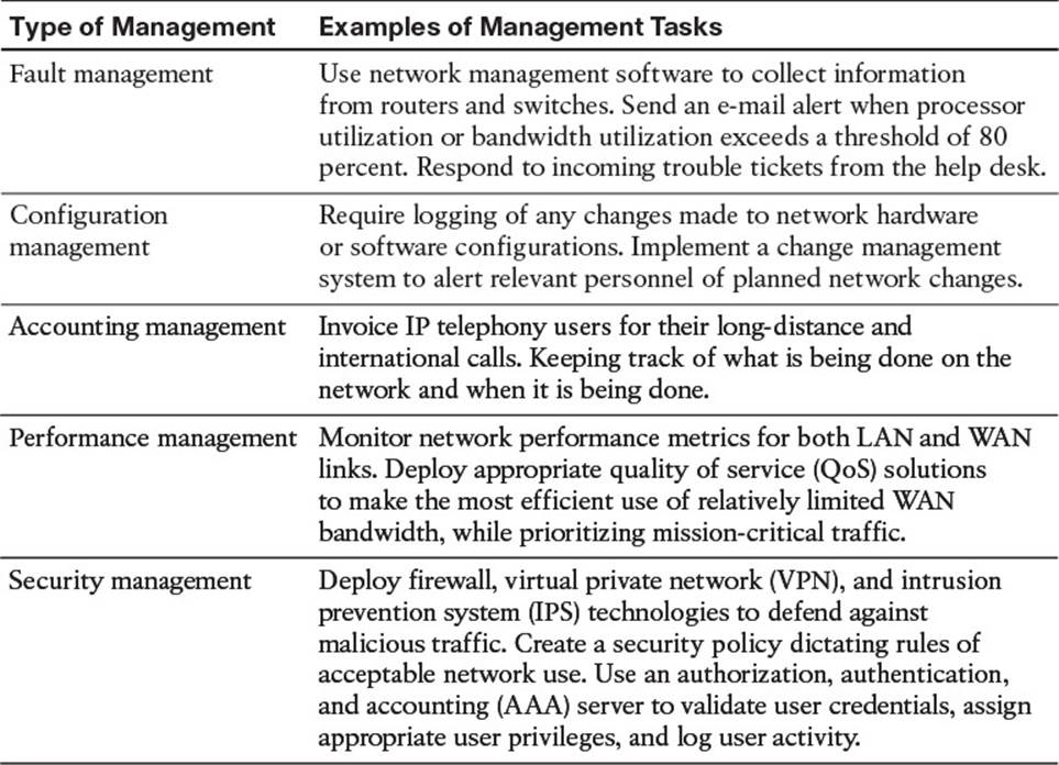
Table 1-3 FCAPS Management Tasks
By clearly outlining a maintenance methodology and defining actionable and measurable processes you can reduce network downtime and more effectively perform interrupt-driven tasks.
Common Maintenance Procedures
No two network maintenance models will be exactly the same, and no two organizations will implement them in exactly the same way, because of the different business drivers involved. However, there are tasks common to nearly all network maintenance models that will be implemented by all organizations regardless of the business drivers. This section discusses common maintenance tasks that all organizations should be performing.
Routine Maintenance Tasks
Regardless of the organization, there will be maintenance tasks in each organization that occur routinely. This routine can be hourly, daily, weekly, monthly, per quarter, or per year. As you can see, the routine can be frequent or infrequent, but it can also be regular or irregular. For example, adding users or moving users and updating the network based on the user changes is going to be different each time. We cannot have a regular schedule for these types of tasks because they are infrequent and irregular. However, backing up a server on a daily basis at 10:00 p.m. is frequent and regular.
The key with all these tasks is that they are routine regardless of them being frequent, infrequent, regular, or irregular and should be present in a listing of procedures contained in a network maintenance model. Following is a listing of such common maintenance tasks:
![]() Configuration changes: Businesses are dynamic environments, where relocation of users from one office space to another, the addition of temporary staffers, and new hires are commonplace. In response to organizational changes, network administrators need to respond by performing appropriate reconfigurations and additions to network hardware and software. These processes are often referred to as moves, adds, and changes.
Configuration changes: Businesses are dynamic environments, where relocation of users from one office space to another, the addition of temporary staffers, and new hires are commonplace. In response to organizational changes, network administrators need to respond by performing appropriate reconfigurations and additions to network hardware and software. These processes are often referred to as moves, adds, and changes.
![]() Replacement of older or failed hardware: As devices age, their reliability and comparable performance tend to deteriorate. Therefore, a common task is the replacement of older hardware, typically with better performing and more feature-rich devices. Occasionally, production devices fail, thus requiring immediate replacement.
Replacement of older or failed hardware: As devices age, their reliability and comparable performance tend to deteriorate. Therefore, a common task is the replacement of older hardware, typically with better performing and more feature-rich devices. Occasionally, production devices fail, thus requiring immediate replacement.
![]() Scheduled backups: Recovery from a major system failure can occur much quicker if network data and device configurations have been regularly backed up. Therefore, a common network maintenance task is to schedule, monitor, and verify backups of selected data and configuration information. These backups can also be useful in recovering important data that was deleted.
Scheduled backups: Recovery from a major system failure can occur much quicker if network data and device configurations have been regularly backed up. Therefore, a common network maintenance task is to schedule, monitor, and verify backups of selected data and configuration information. These backups can also be useful in recovering important data that was deleted.
![]() Updating software: Updates to operating system software (for servers, clients, and even network devices) are periodically released. The updates often address performance issues and security vulnerabilities. New features are also commonly offered in software upgrades. Therefore, performing routine software updates becomes a key network maintenance task.
Updating software: Updates to operating system software (for servers, clients, and even network devices) are periodically released. The updates often address performance issues and security vulnerabilities. New features are also commonly offered in software upgrades. Therefore, performing routine software updates becomes a key network maintenance task.
![]() Monitoring network performance: The collection and interpretation of traffic statistics, bandwidth utilization statistics, and resource utilization statistics for network devices are common goals of network monitoring. Through effective network monitoring (which might involve the collection and examination of log files or the implementation of a high-end network management server), you can better plan for future expansion (that is, capacity planning), anticipate potential issues before they arise, and better understand the nature of the traffic flowing through your network.
Monitoring network performance: The collection and interpretation of traffic statistics, bandwidth utilization statistics, and resource utilization statistics for network devices are common goals of network monitoring. Through effective network monitoring (which might involve the collection and examination of log files or the implementation of a high-end network management server), you can better plan for future expansion (that is, capacity planning), anticipate potential issues before they arise, and better understand the nature of the traffic flowing through your network.
Scheduled Maintenance
Take a moment and define the network maintenance tasks for your network. After doing so, rank them in order of priority. Some tasks will undoubtedly be urgent in nature and need a quick response when things go wrong (for example, replacing a failed router that connects the business to the Internet). Other tasks can be scheduled. For example, you might schedule weekly full backups of your network’s file servers, and you might have a monthly maintenance window, during which time you apply software patches.
By having such a schedule for routine maintenance tasks, network administrators are less likely to forget an important task, because they were busy responding to urgent tasks. Also, users can be made aware of when various network services will be unavailable, due to maintenance windows, thus minimizing the impact on workflow.
Managing Network Changes
Making changes to a network often has the side effect of impacting the productivity of users relying on network resources. In addition, a change to one network component might create a problem for another network component. For example, perhaps a firewall was installed to provide better security for a server farm. However, in addition to common protocols that were allowed to pass through the firewall (for example, DNS, SMTP, POP3, HTTP, HTTPS, and IMAP), one of the servers in the server farm acted as an FTP server, and the firewall configuration did not consider that server. Therefore, the installation of a firewall to better secure a server farm resulted in a troubleshooting issue, where users could no longer reach their FTP server.
The timing of network changes should also be considered. Rather than taking a router down to upgrade its version of Cisco IOS during regular business hours, such an operation should probably be performed during off hours.
Making different organization areas aware of upcoming maintenance operations can also aid in reducing unforeseen problems associated with routine maintenance. For example, suppose that one information technology (IT) department within an organization is responsible for maintaining WAN connections that interconnect various corporate offices, whereas another IT department is charged with performing network backups. If the WAN IT department plans to upgrade the WAN link between a couple of offices at 2:00 a.m. next Tuesday, the IT department in charge of backups should be made aware of that planned upgrade, because a backup of remote data (that is, data accessible over the WAN link to be upgraded) might be scheduled for that same time period.
Some organizations have a formalized change management process, where one department announces online their intention to perform a particular maintenance task during a specified time period. Other departments are then notified of this upcoming change, and determine whether the planned change will conflict with that department’s operations. If a conflict is identified, the departments can work together to accommodate one another’s needs.
Of course, some network maintenance tasks are urgent (for example, a widespread network outage). Those tasks need timely responses, without going through a formalized change management notification process and allowing time for other departments to respond.
When defining a change management system for your organization, consider the following:
![]() Who is responsible for authorizing various types of network changes?
Who is responsible for authorizing various types of network changes?
![]() Which tasks should only be performed during scheduled maintenance windows?
Which tasks should only be performed during scheduled maintenance windows?
![]() What procedures should be followed prior to making a change (for example, backing up a router’s configuration prior to installing a new module in the router)?
What procedures should be followed prior to making a change (for example, backing up a router’s configuration prior to installing a new module in the router)?
![]() What measurable criteria determine the success or failure of a network change?
What measurable criteria determine the success or failure of a network change?
![]() How will a network change be documented, and who is responsible for the documentation?
How will a network change be documented, and who is responsible for the documentation?
![]() How will a rollback plan be created, such that a configuration can be restored to its previous state if the changes resulted in unexpected problems?
How will a rollback plan be created, such that a configuration can be restored to its previous state if the changes resulted in unexpected problems?
![]() Under what circumstances can formalized change management policies be overridden, and what (if any) authorization is required for an override?
Under what circumstances can formalized change management policies be overridden, and what (if any) authorization is required for an override?
Maintaining Network Documentation
Network documentation typically gets created as part of a network’s initial design and installation. However, keeping that documentation current, reflecting all changes made since the network’s installation, should be part of any network maintenance model. Keeping documentation current helps more effectively isolate problems when troubleshooting. In addition, accurate documentation can prove to be valuable to designers who want to scale the network.
At a basic level, network documentation could consist of physical and logical network diagrams, in addition to a listing of network components and their configurations. However, network documentation can be much more detailed, including such components as formalized change management procedures, a listing of contact information (for example, for service providers and points of contact in an organization’s various IT groups), and the rationale for each network change made.
While the specific components in a set of network documentation can vary, just as the procedures in a network maintenance model vary, the following list outlines common elements found in a set of network documentation:
![]() Logical topology diagram: A logical topology diagram shows the interconnection of network segments, the protocols used, and how end users interface with the network, deployed VLANs, and IP addressing, to name a few. However, this diagram is not concerned with the physical locations of network components.
Logical topology diagram: A logical topology diagram shows the interconnection of network segments, the protocols used, and how end users interface with the network, deployed VLANs, and IP addressing, to name a few. However, this diagram is not concerned with the physical locations of network components.
![]() Physical topology diagram: Unlike a logical topology diagram, a physical topology diagram shows how different geographical areas (for example, floors within a building, buildings, or entire sites) interconnect. The diagram reflects where various network components are physically located.
Physical topology diagram: Unlike a logical topology diagram, a physical topology diagram shows how different geographical areas (for example, floors within a building, buildings, or entire sites) interconnect. The diagram reflects where various network components are physically located.
![]() Listing of interconnections: A listing of interconnections could be, for example, a spreadsheet that lists which ports on which devices are used to interconnect network components or connect out to service provider networks. Circuit IDs for service provider circuits might be included in this documentation.
Listing of interconnections: A listing of interconnections could be, for example, a spreadsheet that lists which ports on which devices are used to interconnect network components or connect out to service provider networks. Circuit IDs for service provider circuits might be included in this documentation.
![]() Inventory of network equipment: An inventory of network equipment would include such information as the equipment’s manufacturer, model number, version of software, and modules installed, in addition to information about the licensing of the software, serial number, and an organization’s asset tag number.
Inventory of network equipment: An inventory of network equipment would include such information as the equipment’s manufacturer, model number, version of software, and modules installed, in addition to information about the licensing of the software, serial number, and an organization’s asset tag number.
![]() IP address assignments: An organization might use private IP address space internally and use Network Address Translation (NAT) to translate those private IP address space numbers into publicly routable IP addresses. Alternatively, an organization might have public IP addresses assigned to some or all of their internal devices. A classful IP address space (either public or private) might be subdivided within an organization, resulting in subnets with a nondefault subnet mask. For IPv6 the organization might be manually assigning the interface ID to each device, using EUI-64, or a combination of both. These types of IP addressing specifications would be included in a set of network documentation.
IP address assignments: An organization might use private IP address space internally and use Network Address Translation (NAT) to translate those private IP address space numbers into publicly routable IP addresses. Alternatively, an organization might have public IP addresses assigned to some or all of their internal devices. A classful IP address space (either public or private) might be subdivided within an organization, resulting in subnets with a nondefault subnet mask. For IPv6 the organization might be manually assigning the interface ID to each device, using EUI-64, or a combination of both. These types of IP addressing specifications would be included in a set of network documentation.
![]() Configuration information: When a configuration change is made, the current configuration should be backed up. With a copy of current configuration information, a device could be replaced quicker, in the event of an outage. Beyond having a backup of current configuration information, some network administrators also maintain archival copies of previous configurations. These older configurations could prove useful when attempting to roll back to a previous configuration state or when trying to duplicate a previous configuration in a new location. It is a good practice to name archival copies of previous configurations based on a certain format that makes sense to you. For example, some companies name their archival copies by date, others by function, and still others by a combination of both.
Configuration information: When a configuration change is made, the current configuration should be backed up. With a copy of current configuration information, a device could be replaced quicker, in the event of an outage. Beyond having a backup of current configuration information, some network administrators also maintain archival copies of previous configurations. These older configurations could prove useful when attempting to roll back to a previous configuration state or when trying to duplicate a previous configuration in a new location. It is a good practice to name archival copies of previous configurations based on a certain format that makes sense to you. For example, some companies name their archival copies by date, others by function, and still others by a combination of both.
![]() Original design documents: Documents created during the initial design of a network might provide insight into why certain design decisions were made and how the original designers envisioned future network expansion.
Original design documents: Documents created during the initial design of a network might provide insight into why certain design decisions were made and how the original designers envisioned future network expansion.
Larger network environments often benefit from having step-by-step guidelines for troubleshooting a given network issue. Such a structured approach to troubleshooting helps ensure that all troubleshooting personnel use a common approach. Although a network issue might be successfully resolved through various means, if different personnel troubleshoot using different approaches, at some point those approaches might conflict with one another, resulting in further issues.
For example, consider one network administrator that configures IEEE 802.1Q trunking on Cisco Catalyst switches by disabling Dynamic Trunking Protocol (DTP) frames and forcing a port to act as a trunk port. Another network administrator within the same company configures 802.1Q trunking by setting a port’s trunk state to desirable, which creates a trunk connection only if it receives a DTP frame from the far end of the connection. These two approaches are not compatible, and if each of these two network administrators configured different ends of what they intended to be an 802.1Q trunk, the trunk connection would never come up. This example illustrates the criticality of having clear communication among IT personnel and a set of standardized procedures to ensure consistency in network configuration and troubleshooting practices.
Restoring Operations After a Failure
Although most modern network hardware is very reliable, failures do occur from time to time. Aside from hardware failures, environmental factors could cause a network outage. As a few examples, the failure of an air conditioner unit could cause network equipment to overheat, water leakage due to flooding or plumbing issues could cause hardware failures, and a fire could render the network equipment unusable.
Planning and provisioning hardware and software for such outages before they occur can accelerate recovery time. To efficiently replace a failed (or damaged) device, you should be in possession or have the ability to acquire relatively quickly the following:
![]() Duplicate hardware: The hardware can be stored locally or it can be attainable through a supplier that can get you the device within a certain time based on a service level agreement (SLA).
Duplicate hardware: The hardware can be stored locally or it can be attainable through a supplier that can get you the device within a certain time based on a service level agreement (SLA).
![]() Operating system and application software (along with any applicable licensing) for the device: Although you can get this from the manufacturer (such as Cisco), it is advisable to have an exact copy of the operating systems and application software stored locally for each device you are using in the organization.
Operating system and application software (along with any applicable licensing) for the device: Although you can get this from the manufacturer (such as Cisco), it is advisable to have an exact copy of the operating systems and application software stored locally for each device you are using in the organization.
![]() Backup of device configuration information: When a failure happens, you need to restore your device to its last known good configuration. It is ideal to have a backup of the configuration files on a server in the organization. However, if that is not possible, at a minimum have the configurations documented in Notepad somewhere. You do not want to be caught in a situation where you have no information related to the configuration of a device being restored.
Backup of device configuration information: When a failure happens, you need to restore your device to its last known good configuration. It is ideal to have a backup of the configuration files on a server in the organization. However, if that is not possible, at a minimum have the configurations documented in Notepad somewhere. You do not want to be caught in a situation where you have no information related to the configuration of a device being restored.
Measuring Network Performance
Network monitoring is a proactive approach to network maintenance, enabling you to be alerted to trends and utilization statistics (as a couple of examples). These statistics can forecast future issues, allowing you to be proactive and fix problems before they affect network users. Also, if you work for a service provider, network performance monitoring can ensure that you are providing an appropriate service level to a customer. Conversely, if you are a customer of a service provider, network monitoring can confirm that the service provider is conforming to the SLA for which you are paying.
The Troubleshooting and Network Maintenance Relationship
A structured troubleshooting approach provides step-by-step processes that offer a repeatable consistent plan that makes the troubleshooter more efficient and effective. During our coverage of the structured approach you might have noticed that documentation, baselines, change control, and communication were mentioned. All of these are fundamental assets to your success as a troubleshooter. However, they do not simply appear from the ether, as you have seen from the discussion of network maintenance. For example, documentation and baselines are created at a specific point in time for a device and provide a snapshot of the health and configuration of that device at that point. As a result, we will heavily rely on these resources when issues occur. What happens if someone neglects to update the documentation or baselines based on changes that may have occurred during scheduled maintenance or some past issue? What happens if we have difficulty communicating with others or they withhold information from us? These assets become liabilities as they are unable to address the question: What should be occurring in the network?
As you have seen, network maintenance tasks often include troubleshooting tasks, and vice versa. For example, when installing a new network component as part of ongoing network maintenance, an installer is often required to troubleshoot the installation until the new network component is functioning properly. Also, when troubleshooting a network issue, the troubleshooter might use network documentation (for example, a physical topology diagram created as part of a network maintenance task) to help isolate a problem.
This interrelationship between maintenance and troubleshooting suggests that the effectiveness of your troubleshooting efforts is influenced by the effectiveness of your routine network management tasks. Because these tasks are so interrelated, you might want to take proactive measures to ensure your structured maintenance and troubleshooting processes complement one another. For example, both network troubleshooting and maintenance include a documentation component. Therefore, the value of a centralized repository of documentation increases as a result of its use for both maintenance and troubleshooting efforts.
Maintaining Current Network Documentation
A set of maintained network documentation can dramatically improve the efficiency of troubleshooting efforts. For example, if a troubleshooter is following the path that specific traffic takes through a network, physical and logical topology diagrams could help identify the next network component to check.
A danger with relying on documentation is that if the documentation is dated (not maintained), troubleshooters could be led down an incorrect path because of their reliance on that documentation. Such a scenario is often worse than not having documentation at all, because in the absence of documentation, troubleshooters are not led down the wrong path during the troubleshooting process; they have to create their own path.
Although few argue with the criticality of maintaining current documentation, documenting troubleshooting efforts, in practice, often falls by the wayside. The lack of follow-through when it comes to documenting what happened during a troubleshooting scenario is understandable. The troubleshooter’s focus is on resolving a reported issue in a timely manner (that is, an urgent task) rather than documenting what they are doing at the time (that is, an important task). Following are a few suggestions to help troubleshooters keep in mind the need to document their steps:
![]() Require documentation: By making documentation a component in the troubleshooting flow, troubleshooters know that before a problem report or a trouble ticket can be closed out, they must generate appropriate documentation. This knowledge often motivates troubleshooters to perform some level of documentation (for example, scribbling notes on the back of a piece of paper) as they are performing their tasks, as opposed to later trying to recall what they did from memory, thus increasing the accuracy of the documentation.
Require documentation: By making documentation a component in the troubleshooting flow, troubleshooters know that before a problem report or a trouble ticket can be closed out, they must generate appropriate documentation. This knowledge often motivates troubleshooters to perform some level of documentation (for example, scribbling notes on the back of a piece of paper) as they are performing their tasks, as opposed to later trying to recall what they did from memory, thus increasing the accuracy of the documentation.
![]() Schedule documentation checks: A structured maintenance plan could include a component that routinely requires verification of network documentation and when it was last updated based on timestamps.
Schedule documentation checks: A structured maintenance plan could include a component that routinely requires verification of network documentation and when it was last updated based on timestamps.
![]() Automate documentation: Because manual checks of documentation might not be feasible in larger environments, automated processes could be used to, for example, compare current and backup copies of device configurations. Any difference in the configurations indicates that someone failed to update the backup configuration of a device after making a configuration change to that device. To assist with the automation of backups, Cisco IOS offers the Configuration Replace and Configuration Rollback feature and the Embedded Event Manager.
Automate documentation: Because manual checks of documentation might not be feasible in larger environments, automated processes could be used to, for example, compare current and backup copies of device configurations. Any difference in the configurations indicates that someone failed to update the backup configuration of a device after making a configuration change to that device. To assist with the automation of backups, Cisco IOS offers the Configuration Replace and Configuration Rollback feature and the Embedded Event Manager.
Establishing a Baseline
As previously mentioned, troubleshooting involves knowing what should be happening on the network, observing what is currently happening on the network, and determining the difference between the two. To determine what should be happening on the network, a baseline of network performance should be measured as part of a routine maintenance procedure and updated on a regular basis.
For example, a routine network maintenance procedure might require that a show processes cpu command be periodically issued on all routers in a network, with the output logged and archived. As shown in Example 1-2, the show processes cpu command demonstrates the 5-second, 1-minute, and 5-minute CPU utilization averages. When troubleshooting a performance problem on a router, you could issue this command to determine how a router is currently operating. However, without a baseline as a reference before troubleshooting, you might not be able to draw a meaningful conclusion based on the command output.
Example 1-2 Monitoring Router CPU Utilization
R1# show processes cpu
cpu utilization for five seconds: 18%/18%; one minute: 22%; five minutes: 22%
PID Runtime(ms) Invoked uSecs 5Sec 1Min 5Min TTY process
1 0 1 0 0.00% 0.00% 0.00% 0 chunk Manager
2 4 167 23 0.00% 0.00% 0.00% 0 Load Meter
3 821 188 4367 0.00% 0.13% 0.14% 0 Exec
4 4 1 4000 0.00% 0.13% 0.00% 0 EDDRI_MAIN
5 43026 2180 19736 0.00% 4.09% 4.03% 0 Check heaps
...OUTPUT OMITTED...
Communication
Each of the troubleshooting steps outlined in the structured approach requires clear communication. Table 1-4 describes how communication plays a role in each troubleshooting phase.
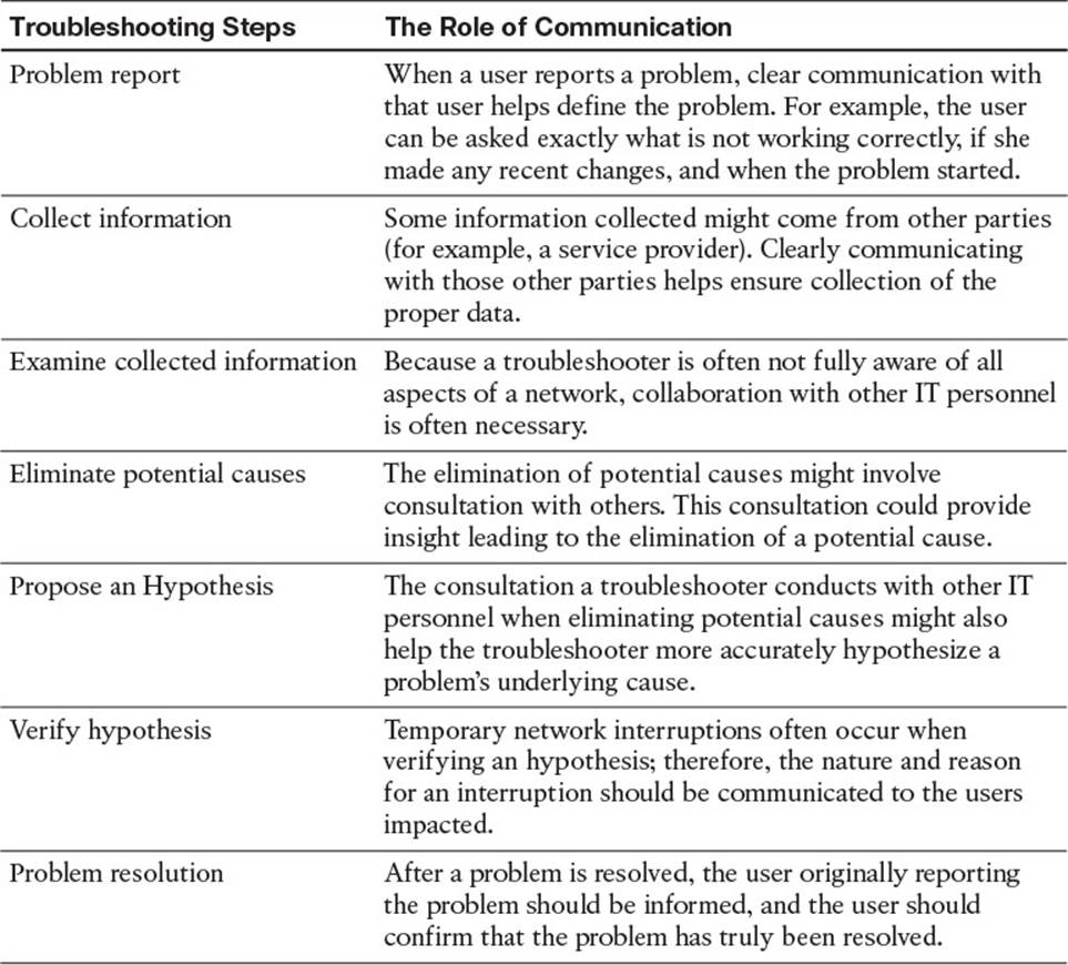
Table 1-4 Importance of Clear Communication During Troubleshooting
Also, depending on the severity of an issue, multiple network administrators could be involved in troubleshooting a problem. Because these troubleshooters might be focused on different tasks at different times, it is possible that no single administrator can report on the overall status of the problem. Therefore, when managing a major outage, those involved in troubleshooting the outage should divert user inquiries to a manager who is in frequent contact with the troubleshooting personnel. As a side benefit, being able to quickly divert user requests for status reports to a manager helps minimize interruptions from users.
Change Management
Managing when changes can be made and by whose authority helps minimize network downtime. In fact, these two factors (that is, when a change is allowed and who can authorize it) are the distinguishing factors between making a change as part of a routine maintenance plan and making a change as part of a troubleshooting process.
The process of change management includes using policies that dictate rules regarding how and when a change can be made and how that change is documented. Consider the following scenario, which illustrates how a maintenance change could be a clue while troubleshooting a problem report:
Last week, a network administrator attempted to better secure a Cisco Catalyst switch by administratively shutting down any ports that were in the down/down state (that is, no physical layer connectivity to a device). This morning, a user reported that her PC could not access network resources. After clearly defining the problem, the troubleshooter asked whether anything had changed, as part of the collect information troubleshooting phase. Even though the user was unaware of any changes, she mentioned that she had just returned from vacation, thus leading the troubleshooter to wonder if any network changes had occurred while the user was on vacation. Thanks to the network’s change management system, the troubleshooter was able to find in the documentation that last week an administrator had administratively shut down this user’s switchport because it was down/down while the user was on vacation and his computer was shut off.
The previous scenario is an excellent example of how following a structured troubleshooting approach, having accurate documentation, and a sound change management policy minimized the total time it took the troubleshooter to solve the problem.
Exam Preparation Tasks
As mentioned in the section “How to Use This Book” in the Introduction, you have a couple of choices for exam preparation: the exercises here; Chapter 22, “Final Preparation;” and the exam simulation questions on the CD-ROM.
Review All Key Topics
Review the most important topics in this chapter, noted with the Key Topic icon in the outer margin of the page. Table 1-5 lists a reference of these key topics and the page numbers on which each is found.
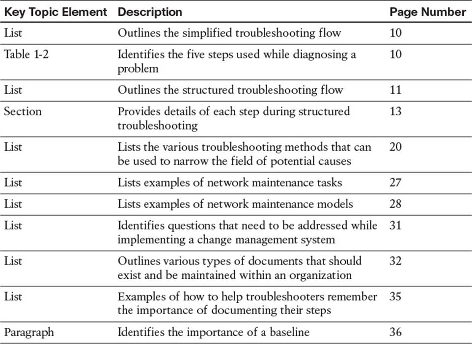
Table 1-5 Key Topics for Chapter 1
Define Key Terms
Define the following key terms from this chapter and check your answers in the glossary:
interrupt-driven task
structured maintenance task
FCAPS
ITIL
Cisco Lifecycle Services
shoot from the hip
top-down method
bottom-up method
divide-and-conquer method
following the traffic path method
comparing configurations method
component swapping method
baseline
change management
documentation
All materials on the site are licensed Creative Commons Attribution-Sharealike 3.0 Unported CC BY-SA 3.0 & GNU Free Documentation License (GFDL)
If you are the copyright holder of any material contained on our site and intend to remove it, please contact our site administrator for approval.
© 2016-2026 All site design rights belong to S.Y.A.