Beginning Arduino Programming (Technology in Action) (2011)
Chapter 10. Serial and I2C
In the last chapter, we looked at how packages of commonly used code called libraries can be useful for working with a range of different kinds of hardware. Usually, these libraries are written for very specific devices or hardware that uses particular components. In this chapter, we will look at a few more libraries for working with more standardized communication protocols that can be used to communicate between many different types of devices that speak the same language. In Chapter 6 we got a taste for using hardware serial communications for monitoring an analog input, although this was a fairly basic one-way communication.
We will revisit hardware serial in this chapter, looking at different functions that can be used to not only send but receive information as well, using Project 9 Serial to Servo, for our discussion. We will then move on to serial communications using a software library instead of the Arduino's built-in hardware to expand the number of things that we can talk to with serial, including the tag reader used in Project 10 RFID Reader. After that, we should have a look at another useful serial communication in the form of the Inter-Integrated Circuit (I2C) data bus, useful for talking with other hardware devices like sensors, displays, and the real-time clock used in Project 11 Serial Time Clock.
What's needed for this chapter:
• Arduino Uno
• Hobby servo (Hitec HS-322 or similar)
• Innovations ID-12 or ID-20 RFID reader and breakout board
• Assorted 125kHz RFID tags
• Piezoelectric speaker or LED and appropriate 220-ohm resistor
• DS1307 real time clock breakout board (SparkFun or Adafruit both make these)
• Hookup wires
• Solderless breadboard
Using Hardware Serial
Every Arduino has at least one hardware serial port. We have already used this port to send our compiled sketches to the Arduino board each time we upload our code. The single hardware serial port on the Arduino Uno is connected to both the USB to Serial convertor chip on the interface board, as well as
digital pins 0 and 1. This allows us to either communicate from our computer's USB port to the Arduino board or for the Arduino board to communicate with other devices.
Serial communication is a process of sending and receiving bytes of data in a sequential manner. Two of the microcontroller's pins are needed for this communication: pin 0 is the receive pin marked RX and pin 1 is the transmit pin marked TX. These pins are also connected to two of those blinking lights that go mad each time we upload a sketch. When connecting two serial devices to each other, it is necessary to cross-connect the TX pin from Device 1 to the RX pin of Device 2 and vice versa. This also means that anytime we are using the hardware serial communications to talk to things, we cannot have anything else connected to pins 0 and 1. Likewise, if an external device is connected to the Arduino RX or TX pins, then we will not be able to upload a new sketch until those pins have been disconnected.
The serial communications protocol sends data in 8-bit chunks, or 1-byte at a time. In the hardware implementation, the serial bus has an available buffer of 128 bytes, meaning that data up to this size will not be lost if the Arduino is busy doing something else and will be available the next time the data is read. Owing to the usefulness of serial for displaying information in terminal windows and other display devices, there are two ways to send this data: as a numerical value and as a character value. As a byte data type, we can send numerical values between 0 and 255 in each transmitted packet.
Instead of using simple numerical values, we can use the char data type to send a character value that corresponds to a standard protocol called ASCII, short for American Standard Code for Information and Interchange. ASCII is a method of coding characters with a value from 0 to 255. For example, the character 'a՛ translates to the value 97. We will revisit this shortly but for now, Table 10-1 provides a chart of the ASCII character codes and the corresponding characters.
Table 10-1. ASCII Character Codes
|
Code |
Character |
Code |
Character |
Code |
Character |
Code |
Character |
Code |
Character |
|
32 |
(sp) |
51 |
3 |
70 |
F |
89 |
Y |
108 |
l |
|
33 |
! |
52 |
4 |
71 |
G |
90 |
Z |
109 |
m |
|
34 |
“ |
53 |
5 |
72 |
H |
91 |
[ |
110 |
n |
|
35 |
# |
54 |
6 |
73 |
I |
92 |
\ |
111 |
o |
|
36 |
$ |
55 |
7 |
74 |
J |
93 |
] |
112 |
p |
|
37 |
% |
56 |
8 |
75 |
K |
94 |
Л |
113 |
q |
|
38 |
& |
57 |
9 |
76 |
L |
95 |
- |
114 |
r |
|
39 |
58 |
77 |
M |
96 |
՝ |
115 |
s |
||
|
40 |
( |
59 |
; |
78 |
N |
97 |
a |
116 |
t |
|
41 |
) |
60 |
< |
79 |
O |
98 |
b |
117 |
u |
|
42 |
* |
61 |
= |
80 |
P |
99 |
c |
118 |
v |
|
Code |
Character |
Code |
Character |
Code |
Character |
Code |
Character |
Code |
Character |
|
43 |
+ |
62 |
> |
81 |
Q |
100 |
d |
119 |
w |
|
44 |
, |
63 |
? |
82 |
R |
101 |
e |
120 |
x |
|
45 |
- |
64 |
@ |
83 |
S |
102 |
f |
121 |
y |
|
46 |
65 |
A |
84 |
T |
103 |
g |
122 |
z |
|
|
47 |
/ |
66 |
B |
85 |
U |
104 |
h |
123 |
{ |
|
48 |
0 |
67 |
C |
86 |
V |
105 |
i |
124 |
| |
|
49 |
1 |
68 |
D |
87 |
W |
106 |
j |
125 |
} |
|
50 |
2 |
69 |
E |
88 |
X |
107 |
k |
126 |
~ |
The ASCII codes also contain something called escape codes. These characters have been around for a while and control things like character returns, tabs, and line feeds or newlines. Later in our example code, we use the sequence '/n', which is one of the control characters, a non-printable character that controls the behavior of a device, to signal when a line has been entered. Table 10-2 provides some of the common escape codes.
Table 10-2. Escape Codes
|
ASCII |
Sequence |
Description |
|
8 |
\b |
Backspace |
|
9 |
\t |
Tab |
|
10 |
\n |
Newline or line feed |
|
13 |
\r |
Carriage return |
Finally, how fast we send our packets of information is called the data rate or sometimes the baud rate. This is a measure of how many pulses are being sent or received in one second, also known as bits per second (bps). A sort of de facto standard baud rate for the Arduino is 9600 bps although the microcontroller is capable of communications at a range of speeds up to 115,200 bps, as needed by whatever specific devices that the Arduino is connected to. Both the sending and receiving device need to be set to the same data rate to ensure that both devices are speaking at the same speed.
With the boring basics for using serial communications out of the way, let's turn our attention to the next project and some of the Serial functions available to us.
Project 9: Serial to Servo
Sending information to the Arduino board to control how it functions is as useful and almost as easy as sending information from the Arduino board. For this project, we will look at the Servo project from the last chapter so that we can use the Serial functions to send data to the Arduino board to control the servo's position. For our sketch to work properly, we need to change the communication mode from No line ending to Newline in the drop-down menu at the bottom of the Serial Monitor.
Hooking It Up
Because the circuit should be familiar, we won't dwell on it too much. Figures 10-1 and 10-2 show the standard servo schematic and illustration that we used before with nothing else needed. The following source code, however, will give us something new and fun to talk about.
SERVO
|
PIN 10 Г |
— |
SIGNAL |
|
+5 VDC — |
+5 VDC |
|
|
GND |
GND
Figure 10-1. Serial Servo schematic
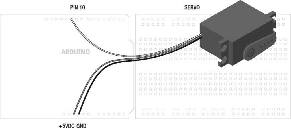
Figure 10-2. Serial Servo illustration
Uploading the Source Code
Where before we have used the Serial functions to send data from the Arduino board to our Serial Monitor, for the purpose of monitoring analog values, the sketch in Listing 10-1 will instead allow us to send data to the Arduino board that has been entered in the Serial Monitor. On the surface, all we need to do is type in an angle for our servo from 0 to 180, corresponding to the angle that we want to position a servo, and hit enter. When the Arduino receives this information, it will process it and move the servo to the proper angle.
We see that because serial communications happens in one-byte chunks and because of the habit of serial to send information in characters rather than numerical values (more on that shortly), we need to do a little work to get the characters that are received converted to proper numbers that can be used to position a servo. So let's upload the following code and have a look at how all this works.
Listing 10-1. Serial Servo Source Code
#include <Servo.h>
Servo servo;
void setup() {
Serial.begin(9600); servo.attach( 10);
}
void loop() { int angle = 0; if (Serial.available()) { byte incomingByte = Serial.read();
while (incomingByte != '\n') {
if (incomingByte >= '0' && incomingByte <= '9') angle = angle * 10 + (incomingByte - '0'); incomingByte = Serial.read();
}
if (angle >= 0 && angle <= 180) { servo.write(angle);
Serial.println(angle);
} else Serial.println("Choose an angle between 0 and 180.");
}
}
Source Code Summary
Just like our example from the last chapter, at the beginning of our sketch we include and create a new instance for the Servo library. While it acts like any other library, we do not need to create an instance of Serial because it is already included as a part of our sketch as standard. In our setup() function, we have the necessary statements to establish the speed of our serial communications and attach our servo to a pin number. Our loop() function begins by starting our servo angle off at 0° and then checks to see if data is available in our serial buffer. If so, it reads the first byte and, so long as the newline escape code has not been sent, will check to see if that value of the byte represents a digit from 0 to 9. This sketch uses the Newline option in the Serial Monitor, so that each time we hit the Enter key, the Serial Monitor sends the escape code '/n' for a new line. We can test for this in our if statement like any other value to know when all of the digits for our angle have been entered.
At this point, the code will put together our angle integer digit-by-digit or byte-by-byte using a little math to convert the ASCII character into its numerical value, and then increases the angle value by a power of ten for each byte received. Once it receives the newline character or '/n' from the Serial Monitor, it will move on to check the angle value that was received to make sure it falls within the capabilities of the servo. If so, it moves the servo to that angle and sends that angle value to the Serial Monitor. If not, it will send a message letting us know to try again. Now let's look at how this is done.
Serial Library
The Serial library is a little different from the other libraries that are a part of the standard Arduino distribution. First, the library is automatically included in our sketches along with the normal Arduino library without us needing to do anything. Second, an instance of the Serial library is already created for us in the background that, on the Arduino Uno, is called Serial, and on the Arduino Mega might be Seriall, Serial2, or Serial3. So when we use one of the upcoming functions, it will be preceded by the instance name Serial and a period to separate the library name from the procedural or function name. As an aside, you might have noticed by now that many of the different libraries have similar procedures, including begin(), print(), write(), and others, so it is important that we get the instance of the library correct or who knows what will happen! Enough posturing, let's move onward with our first Serial function.
beginO
With the Serial library already included for us and an instance called Serial already created, the first thing we need to do to work with the Serial functions is to establish a data transfer speed. To do that we use the begin() function.
Serial.begin(datarate)
Again, our instance name on the Arduino Uno is Serial, so we will stick with that for our instance name. The datarate parameter is the speed measured in bits per second that, for communicating with our computer, should be one of the following speeds: 300, 1200, 2400, 4800, 9600, 14400, 19200, 28800, 38400, 57600, or 115200. Generally, you'll find that 9600 is a fairly common speed and is more than fast enough to do what we want to do. In our project sketch, this function took the following form:
Serial.begin(9600);
This sets up our communication to occur at a speed of 9600 bps. You might have a reason to set a more esoteric speed if your device calls for it, but whatever speed is set, both devices need to be set for the same speed. To do this in the built-in Serial Monitor, there is a drop-down menu in the bottom-right corner of the window where these speeds can be selected.
available()
Since we have already looked at sending data to our computer a few chapters ago, we will first talk about reading data and get back to sending it later in this chapter. Before we can read data from the serial line, we need to know if data is available or not. That's where the appropriately named available() function comes in.
Serial.available()
This function has no parameters but will instead return the number of available bytes waiting in the serial buffer. Remember, the hardware serial port on the Arduino microcontroller has a buffer that can store up to 128 bytes of information so that it doesn't get lost. If no data is waiting for us, it will return 0 and we can use this in an if statement like we did in our project code, as follows:
if (Serial.available()) {
If no data is available in the buffer, then this function will return 0 and evaluate as false. On the other hand, if any data is available, the function will return a value other than 0 that will evaluate as true and we can proceed to read from the buffer. In our example, it didn't matter how much data is in the buffer, only that there was data to be read.
read()
Now that we know there is data waiting for us in our buffer, we can use the read() function to do something with it. While the syntax is simple enough, there are some unusual characteristics that we will need to work through before moving on.
Serial.read()
This function simply returns the first byte of information available in the serial buffer. Because the way our serial communications are structured, each character that we send to the Arduino through the Serial Monitor will be converted to that character's ASCII character value. See, I warned you this would come up again. For example, if we were to send the Arduino the number 1, instead of receiving the numerical integer 1, the Arduino will actually receive the numerical value 49 corresponding to that character's ASCII character code. I know, this is not the most intuitive process here but bear with me.
■ Note As we continue our discussion of characters, remember that the use of single and double quotes is not interchangeable. Single quotes are used for characters, as in the character ‘a’, while double quotes are used for strings of text, as in “Hello, world!”
When we read a byte from the serial line, we are reading one of the ASCII values from 0 to 127 that correspond to the ASCII characters, shown in Table 10-1, that are received through the serial hardware one byte at a time. We can either leave the numerical value alone by assigning it to a numerical data type, or we could store it as a character by using the char data type. From our example code, it is as follows:
byte incomingByte = Serial.read();
This statement assigns the numerical value of the byte that is read from the serial buffer to the variable named incomingByte of the byte data type. We used the byte data type because that is the largest data type that will be returned by the read() function. In this example, if we send the character '0' to the Arduino it will assign the value 48 to the variable incomingByte. Likewise, if we send the character '9', then the value 57 is assigned instead. While these are not the numbers we would initially expect, we can still work with them to do what we need to do. But first, let's look at what would happen hypothetically if we changed the data type to the following:
char incomingByte = Serial.read();
While the read() function will still read the incoming byte as an ASCII character code, by storing this value in a char data type, we will keep the character as a character. So rather than storing the numerical value 97, we would store the character 'a'; instead of 49 we would have the character '1'. It's important to remember that this is not a numerical value—adding two characters may not give you the expected outcome. For example the character '1' added twice is not equal to 2. Written another way, '1' + '1'
!= 2. Instead, it would result in a value of 98, which, if we sent that value back to the Arduino Serial Monitor would gives us the character 'b' .
To make things worse, serial communication happens one byte or one character at a time. So we would not be able to send the numerical value 180 straight from the Serial monitor. What would happen is the Arduino would receive three bytes that correspond to the characters '1' , '8' , and '0' . That's not going to work for the servo. If we refer back to the ASCII Character Codes chart in Table 10-1, we will see that the character '0' has the code 48, '1' is 49, and so on. So if we either subtract the numerical value of 48 from the character code for a number, or subtract the character '0' then we will end up with the actual numerical value that corresponds to the character. For example, we might write a statement like the following:
incomingByte = incomingByte - 48;
Using this statement, we might receive the character '5' that has the ASCII code 53. Subtract 48 from 53 and we end up with 5—a number that can be used with more predictable results. That's nifty, right? We might also write the same statement as the following:
incomingByte = incomingByte - '0';
Every time the compiler sees the single quotes it knows we are talking about the character '0' and not the numerical value 0 and so it makes the substitution for us. Now that we have converted a single digit from a character to a numerical value, we need a way to stitch them together so to speak so that we can get a value like 180. In our earlier code we used the following statement:
angle = angle * 10 + (incomingByte - '0');
The last bit of the statement should look familiar from our previous discussion, so let's look at the operation angle = angle * 10 and what happens in this statement when we send 180 from the Serial Monitor. The first time through our loop it is angle == 0, so angle * 10 will also equal 0. We then add the result of the first incomingByte alter it has been subtracted by the character '0' to get its numerical value, in this case 49 - 48 for a result of 1. That's the first digit. The second time through the loop it is angle == 1; we then multiply by 10 to get a result of 10, and then add the result of the character '0' subtracted from the character '8', or 56 - 48, which is the numerical value 8, when added to 10 is 18.
The third time through the loop, angle == 18, angle * 10 == 180, and then we add the value 0 and now angle == 180. If we hit the Enter key, with the Newline option selected at the bottom of the window, our sketch will quickly work all this out and send the byte value 180 to the servo function. It's not too bad if you just think it through a few times.
Now our code only has a way of converting the character of numbers to actual numerical values. For the most part it will ignore any character other than a digit from 0 through 9.
print()
Now that we know how to read various characters coming in from the Serial input, let's look at a few functions that will send information out through Serial, beginning with the print() function. These functions work a little differently from the read() function, so we will try to be thorough at the risk of putting our readers to sleep. The syntax for this function follows:
Serial.print(data);
The print() function is used for printing ASCII characters to the connected serial device. The data we specify as a parameter can take many different forms, so we need to make sure that the data we want to send is in a format of our choosing. The print() function makes the general assumption that if you specify a value like 33, what you really want to send are the characters ՚3՚ and '3' not the ASCII character code for '!'. There's another function for that, but first, Table 10-3 looks at some of the different examples of various statements and what output will be displayed.
Table 10-3. Examples of Serial.printO
|
Statement |
Output |
|
Serial.print(33); |
33 |
|
Serial.print(3.1459); |
3.15 |
|
Serial.print(‘A'); |
A |
|
Serial.print(“a brave new world”); |
a brave new world |
|
Serial.print(3.1459, 4); |
3.1459 |
|
Serial.print(char(33)); |
! |
These examples begin with the default behavior of the print() function in that by providing a numerical value to the function, the function will display each of the characters that make up each digit of the number. It is important to note that our example does not print the integer 33 but rather the characters '3' and '3'. The second example shows that by default, the print() function will print to two decimal places. Characters like the letter 'a' are enclosed with single quotes while text strings such as "a brave new world" are bracketed in double quotes. Finally, we bend the function a little by specifying additional decimal places for displaying floats and the last example shows how to force a char data type on a numerical value to display the ASCII character for that value.
Each time the print() function is called, data is displayed in one continuous line. To create spacing between multiple values we might use one of the three following statements:
Serial.print(" ");
Serial.print(char(9));
Serial.print ('\t');
The first of these three statements prints the text string of five spaces. Instead, we could use the ASCII code for the escape sequence for tab. By forcing the char() data type, the print() function will tabulate the next printed data. Alternatively, we could use the '/t' escape sequence to create a tab as
well. Likewise, we could use escape sequences to create a new line, but to do that we usually use the following println() function instead.
printlnO
The println() function is short for print line. After printing the specified data, it will return to the next line and start again. Its syntax is the same as print():
Serial.println(data)
This function is the equivalent to either of the following groups of two statements that print the ASCII codes or escape sequence for both return and new line:
Serial.print(char(l3));
Serial.print(char(l0));
or
Serial.print('/r');
Serial.print('/n');
The println() function is a little easier to use and helps to clean up the output that we receive with the Serial Monitor. You'll often see both the print() and println() functions used in conjunction to format the output, making the text easier to read.
writeO
Where the print() function made one assumption about the type of data that we wanted to send, the write() function will make the opposite assumption. Its syntax is also similar to the print() function.
Serial.write(data)
However in this case, the assumption is made that if we specify the value 33 we obviously mean the ASCII character code 33, so this function will display the character '!'. This function effectively replaces the statements Serial.print(33, BYTE); or Serial.print(byte(33)); from versions of the Arduino software prior to 1.0. As these statements are no longer valid, any time we want to display a character by calling its character code, we will need to use the write() function for that. Finally, the write() function can only send data in a single byte, limiting the values to 0–255 or the ASCII codes listed earlier.
And with that, we wrap up the last of the hardware based Serial functions that we will discuss in this chapter. There's a lot we can do with our new form of speaking to the world, but with only one serial port we are a little limited. Say we wanted to connect a new serial device, such as a reader for RFID tags that also uses serial to communicate, we would need to disconnect the device, upload our sketch, and reconnect the device to use it. Needless to say, we would not be able to fully use both the RFID reader and any other serial devices at the same time.
To get around this, we can use a new library called SoftwareSerial to create a software-based serial port on any of the Arduino's digital pins. This is hugely helpful for expanding the number of devices that we can talk to, but it's not without its limits. Our next section will look at how the Software Serial library works and use it to read data embedded in tiny little RFID tags that we can use for all sorts of things.
Project 10: RFID Reader
In this project we will use the Innovations ID-12 Radio Frequency Identification, or RFID reader to read unique identification numbers from cards, key fobs, stickers, and even little capsules. These tags have circuitry in them that when in proximity to a reader, powers up and broadcasts their unique 12-digit hexadecimal ID number. The reader transmits this data through its serial TX pin in 16-byte packets, one byte at a time. Because these tags are each unique, we can use them to inventory the beer in our fridge or to let only our cats in through our cat door.
The Innovations ID-12 is a common RFID reader that uses 125kHz tags and sends its data over a serial connection at a 9600 bps data rate. Other readers in the company's line include the ID-2 and ID-20, with similar functionality but different ranges and antenna requirements. The pins on the bottom of the device are an unusual spacing that is incompatible with our breadboard. So to make things easier for us, we are using a breakout board supplied by SparkFun Electronics that we have soldered some male pins to before soldering in the reader.
Hooking It Up
By using the breakout board from SparkFun, we can plug the reader into our breadboard easily enough, although, with only one row of open pins available, there is not much room to connect wires. So to make the connections, we are using a little area of the breadboard off to the side to connect common wires like +5VDC and Ground. Past the RFID reader, the only other part to connect is a piezo speaker that we used in our Noisy Cricket project to give us a little audible chirp whenever a card has been read, although an LED would work just as well. The wiring for this is stretching things a little, so double-check the schematic and drawings in Figures 10-3 and 10-4 to make sure the correct connections are being made.
+5 VDC
|
GND |
+5 VDC |
|
RST |
BZ |
|
NC |
D0 |
|
NC |
NC |
|
NC |
FS |
|
NC |
ID-12 RFID
+5 VDC
PIEZO
SPEAKER
GND
GND
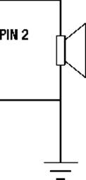
Figure 10-3. RFID Reader schematic
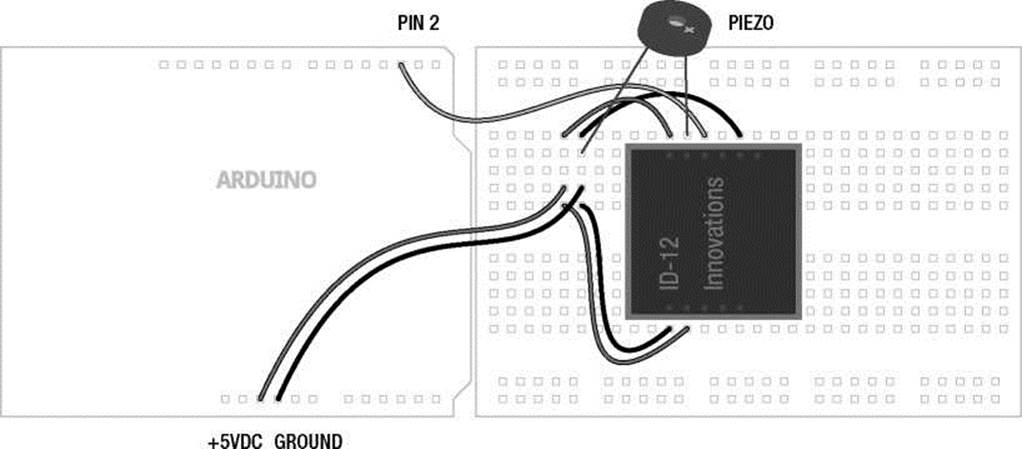
Figure 10-4. RFID Reader illustration
Uploading the Source Code
The source code in Listing 10-2 builds on the basic principals of serial communications that we have been discussing so far, but adds some new wrinkles. First, the reader sends a 16-byte stream of data in the form of hexadecimal ASCII characters each time a tag has been read, but we only really want the unique 12-digit hexadecimal ID number. Second, because this data is sent one byte at a time, we need to read each byte individually and piece it together into a single character string. Finally, we might want to know the tag's ID, compare different tags to known ID numbers, and do certain things based on the tag number. For example, maybe we want to let one cat inside but not the other, or we want our fridge to tell us when we drank the last beer. Following is our source code for this project and a discussion of how it works and the functions that we've used.
Listing 10-2. RFID Reader Source Code
#include <SoftwareSerial.h>
SoftwareSerial rfid(2,3);
char tag01[] = "4500B8F08489"; char tag02[] = "4500B8D36947";
char tagString[13];
void setup() {
Serial.begin(9600);
rfid.begin(9600);
}
void loop() { if (rfid.available()) { if (getTag()) printTag();
}
}
boolean getTag() { char startByte = rfid.read(); delay(20);
if (startByte == 2) { int index = 0; while (index < 12) {
char incomingByte = rfid.read();
tagString[index] = incomingByte; index++;
}
}
rfid.flush(); return true;
}
void printTag() {
for (int i=0; i<12; i++) Serial.print(tagString[i]); Serial.println(compareTags());
}
const char* compareTags() {
if (strncmp(tag01, tagString, 12) == 0) return " Tag 1"; else if (strncmp(tag02, tagString, 12) == 0) return " Tag 2"; else return " Not recognized.";
}
Source Code Summary
To begin with, we need to include the SoftwareSerial library so that we can use it. If we're using a version of the Arduino programming environment prior to 1.0, we need to download and install the library from Mikal Hart's web site (provided later). We then tell the library what to name our instance and what pins we will use. The RFID reader only uses one communication pin, but the library won't let us have an RX pin without a TX pin. We then have a list of known tags that you will definitely want to replace with tags that you own, adding additional arrays as needed. We then set up a place to store the tag that we are currently reading so that we can later compare it to the known tags.
Our normal setup() and loop() functions are as simple as can be, setting up the data rate for both types of serial, and then in the loop() function, checking to see if any data is available. If there is data available, then we make the assumption that a tag has been read. At this point the code calls the getTag() function that will be used to read the incoming 16-byte packet for the tag ID. This packet begins with a start byte that is ignored by our function with the the next 12 bytes to be assigned to the character string tagString[]. The complete format for this packet is as follows:
Start byte (2), 12 bytes (0-9, A-F), Newline (ASCII 10), Return (ASCII 13), End byte (3)
The start of the packet will always contain the ASCII character code for 2 and the end of the packet will be the ASCII code for 3. We check for the start code by reading the first byte after serial is available and compare that to the value 2. After the start byte, we will read the next 12 bytes that will contain one of 16 hexadecimal values including 0 through 9 and the letters A through F. These are added one byte at a time to the tagString[] array, incrementing index each time through the while loop. The remaining three characters, a newline character, carriage return, and the end byte, are unimportant for our purposes and are cleared from the buffer to prevent any problems later.
If everything has been read correctly, the function will return the boolean value true, which is then used to call the printTag() function. This function will print each of the 12 hexadecimal digits to our Serial Monitor so that we can see the value of the tag before printing a call to the compareTags() function. Assuming that we want to do more than just print the value of the tag read, it might be nice to compare that value to known tag IDs. Our last function uses the C function strncmp() (discussed later) to compare the incoming ID with a list of known IDs and will then return a text string or a name for that tag. Rather than returning the text "Tag 1" or "Tag 2", we could as easily change the color of some lighting, print this information to a display, store the information somehow, or even open a door for a cat.
Most of the code should look familiar, even if it appears in a slightly different manner than you might have seen before. We will look at the specific functions of the SoftwareSerial library that are used in our example project that differ from the Serial functions discussed earlier.
SoftwareSerial Library
While Listing 10-2 could work fine with the RFID reader connected to the RX pin, or pin 0 on the Arduino board, it would be a pain to have to disconnect the reader each time we want to upload a new sketch. Or we might have a second serial device that we need to talk to in addition to the RFID reader. In order to have more serial ports than what our hardware comes with, we can use a library that will create a software serial port for us that act almost like the hardware version. To create software-based serial ports, we need to use the SoftwareSerial library, an all-new library as of Arduino version 1.0, based on the previous library formally known as NewSoftSerial, written by Mikal Hart. This new library replaces the old library of the same name and brings with it many improvements and a couple of trade-offs. At the time of this writing, the best place to find out more about the SoftwareSerial library is at the NewSoftSerial web page at http://arduiniana.org/libraries/newsoftserial.
The SoftwareSerial library will allow us to emulate the serial RX and TX pins of a serial port on any of the available I/O pins on the Arduino Uno board. (This library may only work on certain pins on other versions of the Arduino hardware.) While this “virtual” serial port lacks the buffer memory like the native hardware serial (so it cannot receive data in the background), it does share most of the same functions that the Serial library contains, with similar syntax and functionality. The newest version of this library is interrupt driven, which means that it will conflict with hardware interrupts like we used in Chapter 7, as well as the newest Servo library, which is also interrupt driven. If we absolutely must use interrupts in our code, we would either need to use a different or older version of either the SoftwareSerial or Servo libraries. Finally, SoftwareSerial also slows things down a bit, so we should avoid excessively slow data rates and generally stick with hardware serial—unless we absolutely need the extra serial port.
So, let's look at a few of the functions that make our project code work. If we don't discuss most of the functions that we used, that's because they work identically to those same functions in the Serial library.
SoftwareSerial()
To create a new instance of this library we need to use the SoftwareSerial() function to give it a name and specify the RX and TX pin numbers. The syntax follows:
SoftwareSerial name(rxPin, txPin)
The first thing we need to set is the name for our instance. We could use mySerial, softSerial, or anything else we want that's not already taken, including George, but it's probably a good idea to give it a name that relates to the device connected to the serial port and to avoid any confusion should we want to use the hardware Serial functions as well. In our example we used the following statement:
SoftwareSerial rfid(2,3);
Here, we are calling our software serial port rfid to remind us which device that we're talking to. While it is possible to have multiple instances of the SoftwareSerial library, we can only read from or send to one at a time. The timing of these operations could get tricky as we get more devices going at the same time. For example, if we were sending data through a wireless adapter on one serial port, we might miss an incoming tag that needed to be read from the RFID serial port.
The final two parameters that we specified in our example as 2 and 3 are the pin numbers that we will use as receive, RX, and transmit, TX, pins. These can be any of the I/O pins on the Arduino Uno, so long as they are not in use by anything else.
begin()
The begin() function is identical in form to the same function found in the Serial library. Give the function an instance name, in our example rfid, and specify a data rate in bits per second and all should be fine. Although because we are using software on an already burdened microcontroller to emulate what is often done with dedicated hardware, things don't always go according to plan. Data rates of 300 bps or 1200 bps are nearly unusable and you might be pushing your luck with 57,600 bps and over. Just keep in mind that when specifying data rates for software serial ports, if unusual behavior crops up, this data rate may be suspect.
flush()
While the flush() function is the same for the Serial library, we didn't talk about it before because we didn't have a good reason for it. The syntax is another simple one, as follows:
name.flush()
Where name is the name of your serial instance and beyond that there are no parameters and nothing is returned. This function's sole purpose in life is to clear the serial buffer of any waiting data or in the case of SoftwareSerial, to clear any forthcoming data on the serial line. We used this function in our most recent sketch so that we didn't need to worry about the last three characters that the RFID reader sends down the line, whether we want it to or not. We have to do something to either read this data and put it somewhere or simply get rid of it because our code is executed so quickly that these remaining bytes will be taken for tag information and consequently confuse things. Since we know there are 12 bytes that we are interested in and our communications are reasonably accurate, this gives us a way to just get rid of the extra data.
strncmpO
Our last function to talk about here is not actually a function of the Serial libraries, but is rather a part of the standard C library on which Arduino is built. The function strncmp() is used to compare two text strings and is an example of string manipulation. We use this function in our example code to compare the text strings from two different tags to see if they match—kind of like a lock and key. While the Arduino has a String class available with much more advanced capabilities, this function works well enough for our purposes. It has the following syntax:
strncmp(stringl, string2, numberOfCharacters)
This function will compare string1 to string2 up to the maximum number of characters specified.
If the two strings are identical, this function will return the value 0. Take the following hypothetical example:
if (strncmp("goodnight", "room", 4) == 0) Serial.print("goodnight moon");
In this example, the strncmp() function would compare the string "goodnight" to the string "moon" up to a maximum four characters. If these two strings were the same, then the expression would evaluate as true and the following call to Serial.print would be executed. Each of these strings needs to be specified as either the string itself or a pointer to the string. In our example code, it is as follows:
if (strncmp(tag01, tagString, 12) == 0) return " Tag 1";
Here we are using the names of the arrays tag01[] and tagString[] as pointers to the first byte in the array and are then comparing the full 12 digits of each array. If these arrays match, then we can perform an action such as printing the tag's name or some other activity. If they do not match, we can continue to compare the tag that we just read with other known tags to see if there is a match.
While not generally discussed through the official Arduino channels, string manipulation and other functions of the standard C library can be quite useful in the right circumstances. There are many more string functions as well that can be found in a good book on C programming or with a little digging in the great interweb.
From here though, we are going to look at a little different kind of serial communication called I2C that is designed to talk with other kinds of hardware. While many different devices exist, we will start with an easy-to-use, real-time clock module that keeps an accurate time and date with a battery backup for standby operation. With the right commands, it will fairly accurately tell us “when” we are.
Project 11: Serial Time Clock
The Arduino has a fairly precise internal clock, but it's not the most well-suited device to keep track of the date and time. This can be a fairly useful ability to have if we want to keep track of the time the cat comes in to the house or we want to make another digital clock. To get a reasonably accurate date and time with a little backup, we need to use a real-time clock or RTC module. For this project, we will use the venerable DS1307 RTC available on a breakout board from SparkFun Electronics and Adafruit Industries.
The DS1307 is a relatively simple device that uses the Inter-Integrated Circuit communication protocol, or I2C, or sometimes Two Wire—although these two terms are not always interchangeable—to send a 7-bit binary number for the current date and time. I2C is an interesting serial protocol that uses two wires, SDA for data and SCL for clock, to control up to 112 slave devices such as sensors, clocks, FM radios, and smart LEDs, from one master device like our microcontroller. In addition to the data and clock pins, each I2C device will also need a positive and ground connection to a power supply rated for the device. The I2C pins on the Arduino interface board, although not explicitly marked as such, are pins
A4 for SDA (data) and A5 for SCL (clock). These two pins can be connected to multiple devices on a single bus, where all the SDA pins share a common connection, as do all of the SCL pins.
For the following project, we will use the DS1307 RTC connected to the Arduino's I2C bus to display the current date and time. Because we might not want Mountain Standard Time (if you bought the version from SparkFun), we will also provide a sketch for setting the current date and time. This is also useful because, while the RTC is extremely accurate, it has a tendency to shift about ±1 minute every month. The sketches provided try to keep things as simple as possible, leaving the creative application up to the reader.
Hooking It Up
The following schematic and illustration in Figures 10-5 and 10-6 will make the assumption that the RTC is the only device connected to the I2C bus. If we needed to add additional I2C devices, we would need to also add a pair of 10 kilohm pull-up resistors connecting each line of the I2C bus to the positive supply. Otherwise, the wiring is fairly straightforward with a total of four wires needed to get our clock up and running.
|
PIN A4 |
SDA |
|
|
PIN A5 |
SCL |
|
|
NC |
||
|
GND |
||
|
+5 VDC |
+5 VDC |
|
DS1307
GND
Figure 10-5. Serial Time Clock schematic
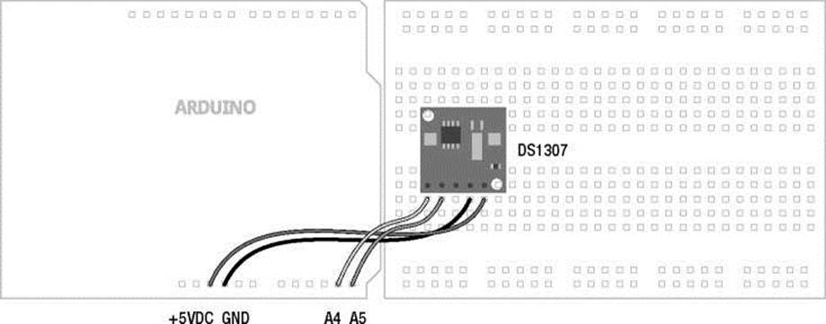
Figure 10-6. Serial Time Clock illustration
Uploading the Source Code
For this project, we have two different sketches—one to simply display the time from the RTC in a text-based, easily readable format and a second to let us set the time in the device using the Serial Monitor. The code might seem a little overwhelming at first, but the first sketch is written to be modular, allowing readers to use it for whatever nefarious means they might dream up. The second sketch is more of a utility than anything, although seeing how to set the time and date from within the code could be handy for something I haven't considered. The format for the text to be displayed should look like the following:
Thursday July 7, 2011 8:35 PM
While the RTC is a 24-hour clock by default, we have used a little if statement to convert this to 12-hour format rather than trying to set the 12-hour clock in the device. To read the date and time, we need to read 7 bytes of data in a row corresponding to a specific order of units, such as second, hour, minute, and so on. The data is inconveniently sent in Binary Coded Decimal or BCD format. This means that each digit is sent as a 4-bit binary number so a decimal 1 would be sent as 0001 and 5 would be sent as 0101. We don't have to worry too much about this as we have a nifty little function to convert this for us. The rest of the code consists of fairly basic print() functions so that we can see the data on our serial monitor.
Following in Listings 10-3 and 10-4 are the two sketches for this project. We can start with the simpler sketch to see how to read the data from the real-time clock and see what kind of data is spit back out. When we have a sense for this code, we will move on to the sketch in Listing 10-4 that really only needs to be run once to set the time for your location. This will demonstrate how to send the time to the device and all of the code that goes along with it. Listing 10-3 will concentrate the discussion on the first sketch while pointing out significant differences in the second.
Listing 10-3. Serial Time Clock Display Source Code #include <Wire.h> const int DS1307 = 0x68;
"Friday", "Saturday"}; "July", "August",
const char* days[] =
{"Sunday", "Monday", "Tuesday", "Wednesday", "Thursday", const char* months[] =
{"January", "February", "March", "April", "May", "June", "September", "October", "November", "December"};
byte second = 0; byte minute = 0; byte hour = 0; byte weekday = 0; byte monthday = 0; byte month = 0; byte year = 0;
byte lastMinute = 0;
void setup() {
Wire.begin();
Serial.begin(9600);
}
void loop() { readTime();
if (minute != lastMinute) { printTime(); lastMinute = minute;
}
}
byte bcdToDec(byte val) { return ((val/16*10) + (val%16));
}
void printTime() { char buffer[3]; const char* aMPm = 0;
Serial.print(days[weekday-1]); Serial.print(" "); Serial.print(months[month-1]); Serial.print(" "); Serial.print(monthday); Serial.print(", 20"); Serial.print(year); Serial.print(" ");
if (hour > 12) { hour -= 12;
AMPM = " PM";
} else AMPM = " AM";
Serial.print(hour);
Serial.print(":");
sprintf(buffer, "%02d", minute);
Serial.print(buffer);
Serial.println(AMPM);
}
void readTime() { Wire.beginTransmission(DS1307); Wire.write(byte(0)); Wire.endTransmission();
Wire.requestFrom(DS1307, 7);
second = bcdToDec(Wire.read()); minute = bcdToDec(Wire.read());
hour = bcdToDec(Wire.read()); weekday = bcdToDec(Wire.read()); monthday = bcdToDec(Wire.read()); month = bcdToDec(Wire.read()); year = bcdToDec(Wire.read());
}
Source Code Summary
This one sketch might seem overwhelming so let's focus on our first sketch in Listing 10-3 before we talk about the following version in Listing 10-4. I promise that it's not too complicated. The code has been broken down into functions, so it's not too hard to understand what each chunk of code does. To start things off, the manufacturer of every I2C device will assign it a unique address for that device. Rather than referring to the hexadecimal value 0x68, a rather confusing number for the address of our RTC, we assign the value a name that relates to our device, or in the following case DS1307:
const int DS1307 = 0x68;
We then set up a pair of character arrays to contain text strings for both the names of the days of the week and the months of the year. We also have a block of byte data type variables where we will assign data for seconds, minutes, hours, and so on.
Our setup() function uses the Wire.begin() and Serial.begin() functions to start both of these communication protocols, one for talking to the RTC and the other for talking to our computer. The loop() function shows one way that an RTC might be useful in place of long delays and in fact, there are no delays in the loop() function at all. We don't even need to display the time, instead we could have an event occur every 5 minutes, every hour on the hour, or even once daily at 7:00 a.m., like a cuckoo clock. We do this by reading the data from the RTC and comparing one of the values against a condition. For example, we decided to only update our time every minute, as follows:
if (minute != lastMinute) {
Here we are checking to see if the minute has changed or a minute has passed before reprinting the current time to the Serial Monitor. This is only one small way of using the RTC as a timer and there could be many, many more. It has the advantage of being very precise and because of the battery backup, is reliable even when the power is off. So let's look at the two functions called in the loop() function of our sketch.
The first function that we call is readTime(), which is used to read the date and time data from our I2C device. This function quite simply starts the communication with the assigned device and then reads the 7 bytes of data that is sent from the device. This is performed in a particular sequence according to the device. The readTime() function also calls another function called bcdToDec(), which nicely converts the BCD-formatted data to decimal-formatted data that we can better put to use.
The second function called is printTime(), which takes six of the seven time measurements and formats them for printing to the screen. This function jumps through some hoops that are not entirely necessary, but make the time a little easier to read. This includes fudging the array position a little, the RTC starts at 1 while our arrays start at 0, so we subtract one from the array position to get the names for the days and months, converting the 24-hour clock to 12-hour, and then buffering the minutes value with another one of those C functions, sprintf(), to create leading zeros so that instead of a time reading of 12:4 we would get the more proper display of 12:04.
So now let's look at the next sketch in Listing 10-4 to see how we can go about setting the time in our real-time clock.
Listing 10-4. Serial Time Clock Setting Source Code #include <Wire.h> const int DS1307 = 0x68; const char* days[] =
{"Sunday", "Monday", "Tuesday", "Wednesday", "Thursday", "Friday", "Saturday"}; const char* months[] =
{"January", "February", "March", "April", "May", "June", "July", "August", "September", "October", "November", "December"};
byte second = 0; byte minute = 0; byte hour = 0; byte weekday = 0; byte monthday = 0; byte month = 0; byte year = 0;
void setup() {
Wire.begin();
Serial.begin(9600);
delay(2000);
Serial.print("The current date and time is: "); printTime();
Serial.println("To set the date and time please select Newline ending to continue."); Serial.println("Would you like to set the date and time now? Y/N"); while (!Serial.available()) delay(10); if (Serial.read() == 'y' || Serial.read() == 'Y') {
Serial.read();
setTime();
Serial.print("The current date and time is now: "); printTime();
}
Serial.println("Goodbye.");
}
void loop() {}
byte decToBcd(byte val) { return ((val/10*16) + (val%10));
}
byte bcdToDec(byte val) { return ((val/16*10) + (val%16));
}
void setTime() {
minute = readByte();
Serial.println(minute); second = 0;
Serial.println("Thank you.");
Wire.beginTransmission(DS1307);
Wire.write(byte(0));
Wire.write(decToBcd(second));
Wire.write(decToBcd(minute));
Wire.write(decToBcd(hour));
Wire.write(decToBcd(weekday));
Wire.write(decToBcd(monthday));
Wire.write(decToBcd(month));
Wire.write(decToBcd(year));
Wire.write(byte(0));
Wire.endTransmission();
}
byte readByte() {
while (!Serial.available()) delay(10); byte reading = 0;
byte incomingByte = Serial.read(); while (incomingByte != '\n') {
if (incomingByte >= '0' && incomingByte <= '9') reading = reading * 10 + (incomingByte - '0'); else;
incomingByte = Serial.read();
}
Serial.flush(); return reading;
}
void printTime() { char buffer[3]; const char* aMPm = 0;
readTime();
Serial.print(days[weekday-1]); Serial.print(" "); Serial.print(months[month-1]); Serial.print(" "); Serial.print(monthday); Serial.print(", 20"); Serial.print(year);
Serial.print(" ");
if (hour > 12) { hour -= 12;
AMPM = " PM";
} else AMPM = " AM";
Serial.print(hour);
Serial.print('':'');
sprintf(buffer, "%02d", minute);
Serial.print(buffer);
Serial.println(AMPM);
}
void readTime() { Wire.beginTransmission(DS1307); Wire.write(byte(0)); Wire.endTransmission();
Wire.requestFrom(DS1307, 7);
second = bcdToDec(Wire.read()); minute = bcdToDec(Wire.read()); hour = bcdToDec(Wire.read()); weekday = bcdToDec(Wire.read()); monthday = bcdToDec(Wire.read()); month = bcdToDec(Wire.read()); year = bcdToDec(Wire.read());
}
Whew. Yeah this one is a lot longer. Although most of this sketch is just repeated from the previous version in Listing 10-3 and the rest of it is taken up in setting the date and time and providing an interface so that we can enter the details. With this sketch uploaded and the Serial Monitor opened, we should be presented with something similar to the following text:
The current date and time is: Thursday July 7, 2011 9:53 PM To set the date and time please select Newline ending to continue.
Would you like to set the date and time now? Y/N
For anyone familiar with Zork1, this is along the same lines with a few text prompts to enter the data to set the real-time clock. With Newline again selected in our Serial Monitor, pressing Y and Enter will start the process of setting the date and time beginning with the year and working down to the minutes. There are no time limits, so we can take as long as we need to enter each number, but there also is no error correction so the sketch will provide feedback as to what was entered. We start the process in the setup() function with a series of statements to print the message. From here we use a while loop in the following line to wait until data has been entered:
while (!Serial.available()) delay(io);
This statement will loop continuously until data has been placed in the serial buffer, signaling user feedback. Once the character 'Y' or 'y' has been entered, we begin with the setT ime () function. This function walks through a series of prompts to input each unit of time. A call to readByte() is used to translate the incoming ASCII characters to decimal values, much like we did at the beginning of this chapter, and then assigns that value to the corresponding unit. Once this is done for all seven units, seconds is automatically assigned 0, each value is then converted using a new function decToBcd() to write each value to our RTC as BCD values.
When all of this has been completed, the time and date are permanently stored in the RTC, at least until the battery backup is removed or it runs out, and then we are returned to the setup() function, where we print the revised date and time and say good-bye. Fairly long and drawn out, at least maybe a bit, but each part of the sketch has a specific job to do to make things a little easier for us to understand. So let's now have a brief look at some of the functions from the Wire library that make all this happen.
Wire Library
The Wire library provides access to a multitude of I2C devices, not just the DS1307 real-time clock, and we used it in Chapter 8 to talk to the BlinkM MinM smart LED. Likewise, while we have typically used analog sensors for input in our projects, these could be replaced with I2C devices that would offer us many benefits that outweigh the added complexity of talking to them. I2C can be used to read from many different devices, such as accelerometers, electronic compasses, and even FM radios. Because every device will have its own requirements, we will only briefly discuss the standard functions of the Wire library here.
beginO
Like other libraries, we need to call the begin() function once in our code, in this case to join the I2C data bus. Its syntax depends on whether the Arduino is to be the master or slave device.
Wire.begin(address)
The address is not needed for the master device, which is usually the Arduino, but there might be reason to set the Arduino as a slave, which would need an address assigned to it. For most things, the address in this parameter is not used.
beginTransmission()
Because we can have so many devices connected on a single data bus, we need to identify the device that we intend to write data to using beginTransmission().
Wire.beginTransmission(address)
The single parameter is the address of the slave device specified in the devices data sheet that we want to transmit data to. This function will create a queue for the write() function to temporarily place data into. In our example code, it is as follows:
Wire.beginTransmission(DSl307);
We defined the variable DS1307 at the beginning of our sketch to contain the address of 0x68 for the DS1307 device. The function needs to be called to transmit data to that device and then ended before sending data to another device on the I2C bus.
endTransmission()
The endTransmission closes the communication with a slave device that was opened with the beginTransmission() function. This function will also send the data that was previously queued up using the write() function.
write()
After opening a connection to a slave device, we can then use the write() function to send bytes of data to the device. The syntax depends on the type of data that we want to send, as follows:
Wire.write(value)
Wire.write(string)
Wire.write(value, quantity)
The data to be written can include a byte or char data type and we can optionally set the number of bytes to be sent. In our example code we used this a couple of ways, as follows:
Wire.write(byte(0));
Wire.write(decToBcd(second));
The first statement is used in our examples in several places, usually to wake up the device and let it know that we are waiting to read data. It is also used in the Time Clock Setting source code to set the date and time by writing the seconds, minutes, hours, and units one byte at a time to the device. We needed to specify the data type byte() in the first example to avoid any problems with ambiguity in the data type.
requestFrom()
We've opened up a channel to our device and written data to it. Now let's look at how to get data from an I2C device. To start, we need to request that data be sent from the device using the requestFrom() function. It's syntax follows:
Wire.requestFrom(address, quantity)
All we need to do is specify the address of the device along with the quantity of bytes that the device should send. From our example code, it is as follows:
Wire.requestFrom(DSl307, 7);
Here we are addressing the DS1307 device and requesting a total of 7 bytes to be sent. Once this data has been sent, we can use the read() function to do something with it.
readO
Now that we should have data waiting for us, we can use the read() function to pull in one byte of data at a time. Since there are no parameters for this function, and it only returns the next available byte to be read, let's look at the following example from our code:
second = bcdToDec(Wire.read());
In this statement, beginning at the far right, we are calling the Wire.read() function to read the first available byte from the slave device. Because this device sends data in BCD format, we need to convert this number to decimal and then assign the value to the variable second. We will later use these variables that contain the various units of time and print their values to the Serial Monitor.
And with that, we have wrapped up our whirlwind tour of I2C and the Wire library. It would be really nice if we had to the space to look even a small percentage of the I2C devices available to us, but sadly, we have to call it a day at some point.
Summary
In this chapter we had a good look at a few different forms of serial communications, from the hardware serial port on the Arduino microcontroller; to the software emulation of serial on any of the general purpose I/O pins; and I2C, a serial communication protocol for talking to various sensors, displays, and other devices. This was only the tip of the iceberg because there are even more communication protocols, like Serial Peripheral Interface, or SPI, and OneWire among others. Hopefully, though, this chapter has shown some of the similarities and a few of the differences between these few protocols to make learning new ones easier than before.
Speaking of learning new things, in the next chapter we are going to continue on with a loose collection of ideas for new projects, new hardware, and new programming languages. We'll even show a few ways that you might contribute back to the open hardware community by sharing what you've learned. With a solid framework for programming the Arduino firmly established, we will open up our discussion to include many of the things that we haven't yet been able to cover in depth. We'll show you some neat things and how they might be put to use, hopefully to inspire even greater projects than previously imagined. No more lengthy sketches and source code summaries, instead we will provide a brief overview of some of the many directions you might want to take with your newfound Arduino knowledge, and leave the rest in your capable hands.
All materials on the site are licensed Creative Commons Attribution-Sharealike 3.0 Unported CC BY-SA 3.0 & GNU Free Documentation License (GFDL)
If you are the copyright holder of any material contained on our site and intend to remove it, please contact our site administrator for approval.
© 2016-2026 All site design rights belong to S.Y.A.