Beginning Arduino Programming (Technology in Action) (2011)
Chapter 11. Continuing On
Hopefully, at this point you might have started to think that programming can actually be a lot of fun and you might be looking for new challenges. Naturally, everything that can be done with the Arduino can't be shown in one book, however, in this chapter we will continue on with new project ideas, new hardware, and new programming languages. We will even look at a few ways that you might get involved with the Arduino and open-source communities to share what you've learned and the projects you've made.
Rather than detail complete projects in this chapter, we will look at a few directions to take your learning and experimentation. These topics are loosely related to programming the Arduino—whether it's through compatible hardware or similar ideologies. I will provide you with a general introduction to each of these topics, as well as some resources for learning more, and give you a sense of how these things can interface with the Arduino. This is the bonus round really, just enough to keep you continuing on.
Build More Projects
The first thing to do, of course, with your newfound Arduino skills is build more projects! We couldn't cover every project idea in this one book and I tried to keep what we did talk about to the very basics. So, here are a few things that I would have loved to have previously discussed in more depth that you might be able to try out.
Bonus Project 1: Make Something Tweet
Remember that Arduino Ethernet Shield I suggested was a good idea when we learned how to log data on an SD card? Well, if you have this shield, or maybe one of the new boards called the Arduino Ethernet, then you can make your next project tweet. Maybe you're inspired by the functionality of the Botanicalls shown in Chapter 1, but rather than knowing that your plants need water, you want to know instead when the coffee in the office is ready or the beer keg has been emptied, maybe you really need to keep track of the irregular hours that your cat (or teenager?) enters and leaves the house, or maybe you just want to display an updated status of your whereabouts on a display in your office no matter where you are.
What’s Needed
To get started tweeting with the Arduino, we need to use a few libraries and the appropriate hardware on the Arduino, along with a Twitter account and a little utility that was written especially for this that can be found at www.arduino.cc/playground/Code/TwitterLibrary. To begin, we will need the Arduino Ethernet Shield, as shown in Figure 11-1.
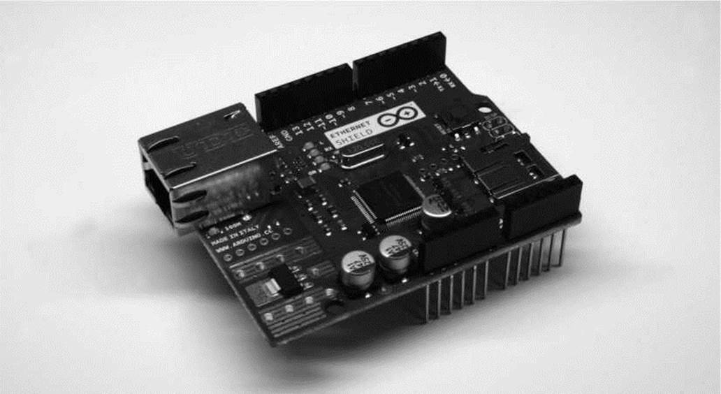
Figure 11-1. Arduino Ethernet Shield
With that in hand, we need to plug it into the Arduino and connect it to our network using an Ethernet cable. Next up, we need to install two of the four Arduino libraries, available from the earlier link, used in this application: Twitter and EthernetDNS. The other two libraries, SPI and Ethernet, come with Arduino versions 0019 and newer. Next up, we can start with the example sketch, SimplePost, included with the Twitter library and shown in Figure 11-2.
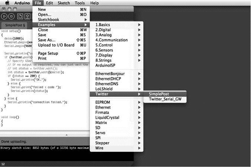
Figure 11-2. Twitter library example
When the libraries are placed correctly in the libraries folder, the example sketch will show up in the File > Examples > Twitter menu, as shown. If not, you might need to hunt down the correct library folder.
■ Note You might have noticed that we’re using the 0022 version of Arduino in Figure 11-2. At the time of this writing, the Twitter library did not play nice with the 1.0 beta but the Arduino developers are working hard and I’m sure this will be fixed by the time this book is published.
Making It Work
With our sketch open, we need to set three things to make this work. The first thing to set is the MAC address of the Ethernet adapter. This is usually printed on a little label on the bottom of the Ethernet shield and entered in the array mac[]. Second, we need to find an available IP address on our network and enter it into the array named ip[]. Finally, we need to obtain an authorization token from Twitter to be able to use its services and enter this token in the Twitter twitter() object. To obtain this token, our example sketch uses the Arduino-tweet application at http://arduino-tweet.appspot.com. With all of that in place, we can upload the sketch to the interface board and then open up the Serial Monitor to see what's going on. When everything works, we should see the tweet posted by our Arduino, as shown in Figure 11-3.
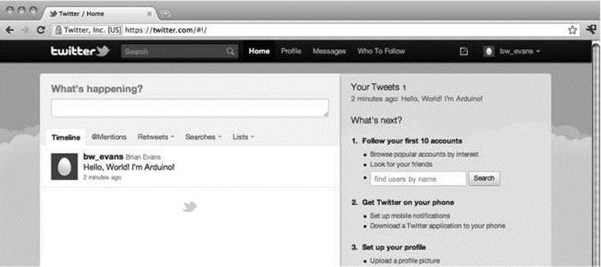
Figure 11-3. Something tweeted
Okay, so “Hello, World!I'm Arduino!”is perhaps not the most exciting thing to tweet, but it's a start right? With the right kind of sensors, I'm sure you can find something interesting to make tweet using these libraries. Or maybe instead, you can get the Arduino to display incoming tweets on an LCD or other form of display. For more ideas on what to do with the Arduino Ethernet Shield, check out the following tutorials from bildr, the modular tutorial site:
http://bildr.org/20ll/06/arduino-ethernet-pin-control/
http://bildr.org/20ll/06/arduino-ethernet-client/
Bonus Project 2: Make Something Move
We also didn't get a chance to talk much about making things move. We did have a look at connecting a small DC fan back in Chapter 6, and in Chapter 9 we discussed servo and stepper motors as way to make something move with fairly precise positioning. You might instead want to make something move using common and very popular DC motors. As explained in more depth in the next chapter, DC motors come with and without gearboxes and run at a variety of speeds with different current requirements. The following are three possible things that we can look for when connecting DC motors to the Arduino:
• The motor can run at variable speeds
• The motor can run at high currents
• The motor can switch directions
Of these three things—in a simple circuit that we are not throwing the kitchen sink at—we can usually do two of these at any one time. So for example, we can run a motor at high currents and at a range of speeds, but it's a little more difficult to get it to switch directions. Instead, we could have a motor change direction, but we would then need to decide whether a high current or variable speeds is more important.
The code to work with DC motors is fairly simple using a combination of digital and/or analog outputs, which we covered somewhat thoroughly in Chapters 5 and 6. The circuits, however, are a little more complex, and we won't be able to go into all the complexities here, but let's cover three simple ways to interface DC motors that illustrate the rule of variable speeds/high currents/switching directions with a general explanation on how to make each circuit work. We'll leave the specifics up to you for further exploration.
MOSFETs
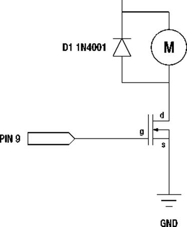
The Metal Oxide Field Effect Transistor, or MOSFET, is one of the simpler components to use with DC motors along with the basic transistor shown in Figure 6-4 of Chapter 6. The following circuit in Figures 11-4 and 11-5 uses an IRL540 MOSFET, although others would work as well, to switch a motor with a load of up to about 20 amps. That's a pretty big motor! The IRL540 can also switch at a very fast rate of speed, so we can use PWM to control the speed of a motor connected in this circuit. This circuit also uses a 1N4001 diode connected to the positive and negative side of the motor to prevent any electrical surges from the motor damaging the MOSFET.
■ Note In all of these motor circuits, we have a pin that is marked +V MOTOR. While we have connected these to our standard +5 VDC supply because our motors worked on +5 volts, you may need to connect these pins to a larger power supply, depending on the needs of your motor.
+V MOTOR
MOTOR
Q1 IRL540
Figure 11-4. MOSFET and DC Motor schematic
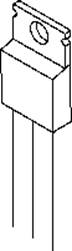
ց d s
GROUND PIN 9
+5VDC
Figure 11-5. MOSFET and DC Motor illustration
When connected to pin 9 on the Arduino board, we can either control the motor digitally, meaning turn it on or off, using the digitalWrite() function or we could instead control the speed of the motor using PWM and the analogWrite() function with 0 being off and 255 being full speed forward. This high current and variable speed comes with the drawback that we can only control the motor in one direction.
H-Bridges
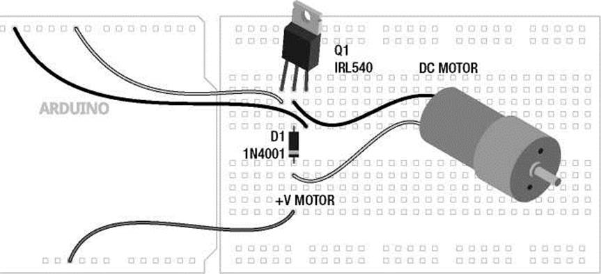
We have already used the SN754410 H-bridge integrated circuit in Chapter 9 to control a bipolar stepper motor, but we can also use it to control up to two DC motors, although we have only shown it with one in Figures 11-6 and 11-7. By using a couple of the Arduino's digital outputs, we can control the direction of the motor as well as its speed using one of the PWM pins. This, however, comes at the cost of the size of the motor, with the SN754410 only capable of 1-amp output capacity.
GND
GND
PIN 10 PIN 8
MOTOR M
PIN 9 +V MOTOR
|
1,2 EN |
+5 VDC |
|
1 IN |
4 IN |
|
1 OUT |
4 OUT |
|
GND |
GND |
|
GND |
GND |
|
2 OUT |
3 OUT |
|
2 IN |
3 IN |
|
+V MOTOR 3,4 EN |
|
SN754410
+5 VDC
Figure 11-6. H-Bridge and DC Motor schematic
PINS 8, 9, 10
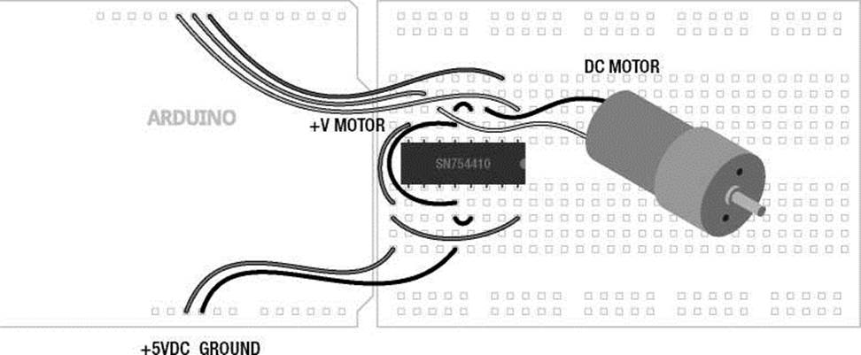
Figure 11-7. H-Bridge and DC Motor illustration
When configured as shown, pins 8 and 9 will control the direction of the motor using digital outputs and the digitalWrite() function, while pin 10 will control the motor's speed using analogWrite() with 0 being off and 255 being full speed ahead. To get a sense of how these two pins control the direction of the motor, see Table 11-1.
Table 11-1. H-Bridge Function
|
Input 1 |
Input 2 |
Function |
|
HIGH |
LOW |
Spin motor clockwise |
|
LOW |
HIGH |
Spin motor counter-clockwise |
|
LOW |
LOW |
Disable motor / free spin |
|
HIGH |
HIGH |
Motor brake / full stop |
By writing a HIGH signal on pin 8 and a LOW signal on pin 9, then the motor will spin one direction and will reverse direction when pin 8 is LOW and pin 9 is HIGH. If both pins are LOW, then the motor will have 0 voltage and will spin freely—assuming it's not a gear motor. If both pins are set to HIGH, then current will be applied to both sides of the motor, locking the motors position just like an electronic brake.
From here, all you need to do is set the direction using pins 8 and 9, then control the speed with analogWrite() on Pin 10, and you're up and running with an H-bridge.
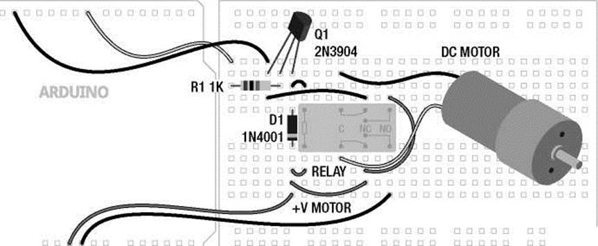
Relays
In this project, we will briefly look at using a mechanically switching relay to handle high currents and switch directions with a DC motor. Relays work a little like the light switches in our walls, with little metal contacts inside the switch, which are physically moved whenever the switch is activated, completing a circuit. This is done by sending a digital signal to a little magnetic coil inside the relay that activates the switch for us. In Figures 11-8 and 11-9 we are using the Axicom D2N V23105 relay with a +5v coil that can control a motor of up to 3 amps at a ridiculously high voltage of +220 volts.
+5 VDC +V MOTOR
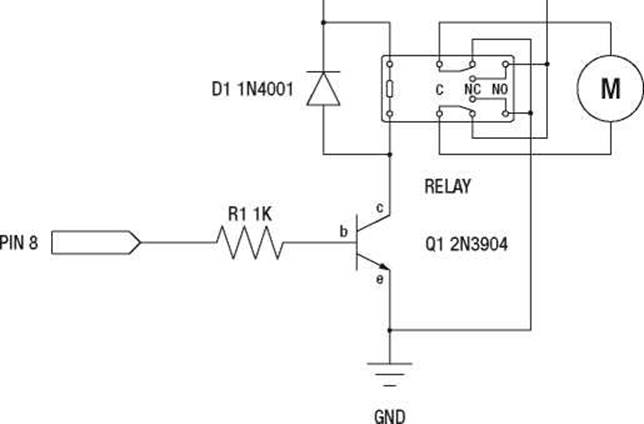
MOTOR
Figure 11-8. Relay and DC Motor schematic
e b c
GROUND
PIN 8
□ □ □ □ □ □
+5VDC GROUND
Figure 11-9. Relay and DC Motor illustration
This circuit is a little more complex, but it gives us bi-directional control of the motor using a single digital output, and we have a high amount of current to play with. Alas, this is at the cost of the ability to control the speed of the motor because the relay simply cannot switch at a very fast speed. Inside of the relay there are actually two switches with two positions each: normally open and normally closed. With the wiring as shown, when the relay is activated, the motor will be connected to the power supply in one direction and when the relay is off the motor will be connected in the opposite direction. This also means that the motor will always spin in one direction or another. This circuit doesn't quit!
While the coil of the relay is rated for +5v, I don't trust it with the microcontroller, so we've used a 2N3904 transistor to switch the relay on or off and a 1N4001 diode to protect the transistor from surges, like we did with the MOSFET. And finally, no two relays are ever really the same, so double-check the wiring for your relay before wiring this up.
That might have been a lot to take in, but the code is really simple and this brief little introduction to motors and the Arduino should be enough to send you on your way to find more information and give it a try.
Bonus Project 3: Mega-Size Something
Our final project idea isn't so much a project as it is a neat piece of hardware. Throughout this book, our projects have been written for the standard Arduino interface board, the Arduino Uno. The Uno, however, has a bigger brother called the Arduino Mega 2560, shown in Figure 11-10, and its capabilities should inspire new projects.
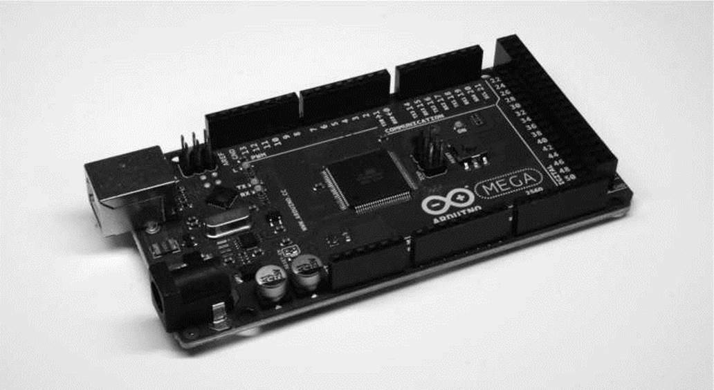
Figure 11-10. Arduino Mega 2560
The Mega 2560 is bigger than the little Uno in every way—it has 54 input and output pins, more than four times that of the Uno, 14 of which can be used for PWM; ten more analog inputs, for 16 total; four hardware serial ports instead of one; eight times the program memory at 256 kilobytes and four times the RAM and EEPROM space. Not only can it hold bigger sketches, it can, for example, control the speed of 14 DC motors, read from 16 different analog sensors, or even easily switch 128 LEDs with no additional hardware or tricky wiring needed. While there are always extra hardware components that can give the Uno similar levels of capabilities, the Mega 2560 doesn't need them, simplifying your wiring and your code.
Speaking of code, the Arduino Mega 2560 works pretty much just like its little brother. The pins used for I2C are in a different location and there are extra hardware serial ports, but otherwise the same code should work just fine on the Mega. The Mega is also compatible with most of the shields made for the Uno, including the Ethernet Shield, so the next time you need to blink a ton of LEDs, you might want to consider using the Arduino Mega 2560.
Learn Another Language
Now that you've got a decent handle on programming Arduino C, there is a world of new open source programming languages out there ready to be taken on. While altogether different from the Arduino's C-based language, we're going to have a quick glance over a couple of these programming languages that work really well with the Arduino platform and have complementary design ideologies. These languages will open up possibilities for using the Arduino to generate sound and images, manipulate video, and make things even more interactive. In addition to introducing the languages here, we will also have a look at a group of Arduino sketches called Firmata that make using inputs and outputs on the Arduino a whole lot easier.
Firmata
Firmata is an Arduino firmware that is loaded onto the Arduino board to allow other programming languages to easily communicate with sensors, motors, and other devices. Rather than writing a custom sketch for the Arduino each time we need to communicate with a computer, like we did in our Serial-based projects in Chapter 10, we can use the standard communication protocols that have been written for us already in Firmata, along with code that is freely available for many of the more popular programming languages. Getting started with Firmata is easy enough, as the most recent versions are included with the standard Arduino distribution. There are several different versions of Firmata available, so it might take a little experimentation to find the version that works for your purposes. All we need to do is open a version of Firmata as shown in Figure 11-11; we're using the version called StandardFirmata_2_2_forUno_0_3. Upload this sketch to the Arduino interface board, as usual.
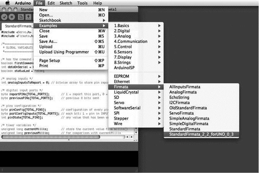
Figure 11-11. Opening Firmata
With Firmata loaded on the Arduino board, we need to find a matching object or test program for the language we want to use with it. We'll get to using Firmata with other languages in a moment, so just to test that everything works, we can use the Firmata Test Program, available from http: //firmata.org/ wiki/Main_Page (see Figure 11-12).
|
Firmata Test |
|
|
Pin 2 Output |
i 1 Low |
|
Pin 3 Output |
HI to» 1 |
|
Pin 4 Output |
i ^ Low |
|
Pin 5 Output |
i ] Low |
|
Pin 6 ! Output |
7Ц low "1 |
|
Pin 7 Output |
Til Low 1 |
|
Pin 8 Output |
Tl low 1 |
|
Pin 9 Servo |
*i=о |
|
Pin 10 Output |
i ] Low 1 |
|
Pin 11 PWM |
3=o- |
|
Pin 12 Output |
Tl Low 1 |
|
Pin 13 Output |
|
|
Pin 16 Analog |
; 1 AO: 75 |
|
Pin 17 Analog |
Таі: 88 |
|
Pin 18 Analog |
T A2: 93 |
|
Pin 19 Analog |
Ta3: 98 |
|
Pin 20 Analog |
1A4: 71 |
|
Pin 21 Analog |
'i i AS: 81 |
|
Pin 22 1 Analog |
T A6: 79 |
|
Pin 23 [ Analog |
T A7: 115 |
/dev/cu.usbmodemfdl41 StandardFirmata_2_2_forUNO_0_3-2.2 Tx:577 Rx:106003
Figure 11-12. Firmata test program
With this simple program running, we can configure any of the I/O pins as Input, Output, PWM (for analog output), Servo, and Analog (for analog input). Once configured, we can toggle the state of digital outputs from Low to High, read the state of digital inputs, change the PWM value of PWM pins, move a servo to a different position, and read the values from our Analog inputs. Pretty nifty for a simple little test program, but it also shows some of the versatility in using Firmata with our computer in that it allows us to concentrate on learning a new language without getting bogged down in writing new Arduino code each time we need to do something.
While Firmata host software has been written for a range of software, including Visual Basic, .NET framework, C++/openFrameworks, C#, Perl, Python, Flash, and more, we will look at the use of Firmata on two of the more like-minded programming languages as a way to introduce these packages as candidates for where to go next.
Processing
Processing is the free and open-source programming language that in many ways started things off for the Arduino. Processing was designed by two MIT students, Casey Reas and Ben Fry, as a way to initially make programming visual design and graphics easier for the non-programmer through a text-based language used to generate images. Unlike Arduino, Processing is based off of Java, loosely related to C by lineage; however, like the Arduino, Processing gets its power and usability from carefully-written libraries of code. Processing has gained wide acclaim and has been used in commercials for Nike and Hewlett-Packard, music videos for Modest Mouse and Radiohead, and all manner of art installations everywhere. It is a really good language for visualizing data, creating immersive and interactive graphics, and generating moving images.
To get started using Processing with the Arduino, we need to download Processing and the Arduino Library for Processing from http://processing.org/download and
www.arduino.cc/playground/Interfacing/Processing respectively. Figure 11-13 shows the arduino_output sketch included with this last download.
arduino_output
arduino_output | Processing 1.5
OO BK3K3B
import processing.serial.*;
import cc.arduino.*;
Arduino arduino;
color off = color(4, 79, 111); color on > color(84, 145, 158)
int[] values = { Arduino.LOW, Arduino.LOW, Arduino.LOW, Arduinol Arduino.LOW, Arduino.LOW, Arduino.LOW, Arduino.LOW, Arduino.L0| Arduino.LOW, Arduino.LOW, Arduino.LOW, Arduino.LOW, Arduino.L0|
println(Arduino.list()); arduino = new Arduino(thi
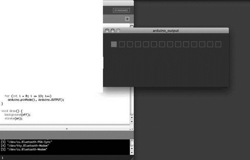
Figure 11-13. Simple Processing sketch
If Processing looks familiar, that's because the Processing development environment is the same one that the Arduino environment is built from. Things are a little different and the language will take some getting used to, but once you have a firm grasp of programming the Arduino, it's not overly difficult to get up to speed on Processing.
That is only the briefest introduction to working with Processing. For more information on using the Firmata, Arduino, Processing triumvirate check out the Arduino Playground site, as well as the (somewhat outdated) tutorial from Golan Levin at www.flong.com/blog/2010/installing-arduino-with-firmata-for-maxmsp-and-processing-in-osx. The creators of Processing, Casey Reas and Ben Fry, have also done outstanding jobs writing about the language with their books Getting Started with Processing (O'Reilly Media, 2010) and Processing: A Programming Handbook for Visual Designers and Artists (MIT Press, 2007). Both are great books to pick up if you are interested in learning more about Processing.
PureData
PureData, or PD, is quite the departure from the text-based programming of Arduino and Processing. PD is a graphical programming environment where lines of code and functions are replaced by reusable objects that are connected together with actual lines that link one object to another—kind of like the patches from an analog synthesizer. PD is particularly adept at audio, image, and video manipulation, and is a loosely related, free and open-source alternative to Max/MSP. If you are interested in using the Arduino to interface with sound and video generated on a computer, then PD would be a good choice. More information and downloads can be found at http://puredata.info.
Figure 11-14 shows a simple PD patch that reads sensor data from an analog sensor connected to pin A0 on an Arduino board with the SimpleAnalog version of Firmata loaded on it. It then uses this sensor data to control the amplitude and frequency of a band pass filter applied to a static noise signal.
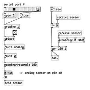
Figure 11-14. Simple PureData patch
This simple patch demonstrates some of the basic capabilities of PD and gives you a taste for what it's like to program in a graphical language. For this patch to work, we need to download the Pduino object available from http://at.or.at/hans/pd/objects.html. For some help getting started with Pduino, check out the FLOSS Manual on PureData at http://en.flossmanuals.net/pure-data/ch061_starting-pduino. Included with the Pduino download are several example files, including arduino-test.pd, shown in Figure 11-15.
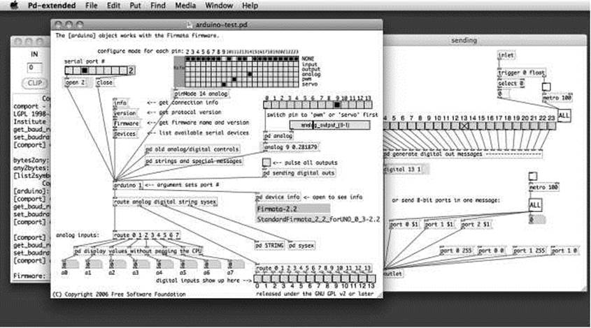
Figure 11-15. PureData Pduino object
This patch is a good place to start, as it shows many of the possibilities of interfacing an Arduino running Firmata and PureData. Here we can configure the various states for each of the I/O pins, toggle the states of outputs, change the PWM values or servo positions using a slider, and read the states and values of input pins. Again, the best place to read up on PD is at the FLOSS Manuals web site on PureData at http://en.flossmanuals.net/pure-data.
Contribute to the Community
As we discussed way back in the first chapter, the Arduino community is one of the greatest strengths of the Arduino platform and constantly drives further improvement and development of the platform as a whole. Everyone needs a question answered at one point or another so one of the easiest ways to contribute back to the community is by being there with friendly advice on various online forums. Alternatively, just sharing the types of projects that you've made using the Arduino can provide inspiration and answers to someone that didn't even know they needed help. This section will provide a few specific ways that you can contribute back to the community—each one of these communities are not only a great place to share your projects, they are also a great place for getting inspired by new project ideas.
Participate in Online Forums
There are all sorts of online forums where all manner of makers post questions, share project ideas, suggest changes to the platform, and contribute to general discussions of all things Arduino. Nowhere is this more prevalent than straight from the source itself —the official Arduino forum at http://arduino.cc/forum/, shown in Figure 11-16.
|
՝ ^"V/ ^Arduino Forum - Index |
|||
|
0 © arduino.cc/forum/index.php |
_____ |
||
|
ѲѲ ARDUINO FORUM |
1C Searchj Hello bwevans 0 new messages I unread posts I replie: are you looking for our old forum? |
||
|
~ 1 Arduino Forum |
|||
|
Using Arduino |
* |
1 |
|
|
Installation & Troubleshooting For problems with Arduino itself, NOT your project Last post: Re: Program corruption?... by AWOL on Today at 11:02:27 AM |
5610 Posts |
1009 |
|
|
Project Guidance Advice on general approaches or feasibility Last post: Re: multiple references by CrossRoads on Today at 12:46:41 PM |
16101 Posts |
2183 |
|
|
Programming Questions Understanding the language, error messages, etc. Last post: Re Need an if statement... by AWOL on Today at 12:50:13 PM |
22125 Posts |
2807 |
|
|
General Electronics Resistors, capacitors, breadboards, soldering, etc. Last post: Re need help to identif... by The_Bongmaster on Today at 11:33:19 AM |
8337 Posts |
976 |
|
|
Microcontrollers Standalone or alternative microcontrollers, in-system programming, bootloaders, etc. Last post: Re ATmega 328 with Uno ... by Magician on Today at 07:39:12 AM |
3533 Posts |
432 |
|
|
LEDs and Multiplexing Controlling lots of inputs and outputs Last post: Re: Multiplex 30 outputs... by CrossRoads on Today at 12:11:20 PM |
3294 Posts |
427 |
|
|
Displays ■■ LCDs, OLEDs, PAL, NTSC, etc. Last post: Re 4D LABS pLCD-32PT(SG... by smatthew on Today at 08:06:34 AM |
2928 Posts |
375 |
|
|
Audio Sound processing and generation, using WAV and MP3 players, using MIDI Last post: Re Arduino and LM386 by Magician on Today at 10:39:55 AM |
1408 Posts |
199 |
|
|
Motors, Mechanics, and Power Controlling big heavy things that move, need high voltages, high current, or both Ust post Re L298n Hbridge + Pote... by hullaitl on Today at 10:14:26 AM |
4384 Posts |
632 |
|
|
Sensors sensors, anatog inputs, filtering, etc. Last post Re: Using accelerometer... by cydegadget on Today at 12:45:20 PM |
4901 Posts |
711 |
|
|
Networking, Protocols, and Devices ■■ I2C, SPI, XBee, GPS, etc. Last post Re 2 XBees, 2 Arduinos,... by czyskows on Today at 08:29:53 AM |
4962 Posts |
847 |
|
|
Storage Using Arduino to interface SD cards, floppy drives, harddrives, EEPROMs, etc Ust post Re: Interfacing to SD ca... by fatl6lib on July 21, 2011, 07:21:55 AM |
1271 Posts |
167 |
|
|
Interfacing w/ Software on the Computer Firmata, Processing, Max/MSP, PureData, WW, etc. Ust post Re: Java + Arduino by war_of_hades on Today at 12:35:43 PM |
1896 Posts |
402 |
|
|
Topics |
1 |
||
|
E-Textiles and Craft Smart textiles, flexible conductive materials, electroluminiscent materials Ust post Re: conductive rubber by trendski on July 11, 2011,08:52:16 AM |
56 |
T10 |
1 |
|
__ Science and Measurement |
m |
||
Figure 11-16. Arduino forum
With a multitude of categories for discussion and topics that range from electronics, programming, e-textiles, and even interactive art, there is always something to talk about on the Arduino forums. There are even international forums of a few different varieties. Sign up for a username so you can participate in the discussions and even use your username to contribute to the Arduino Playground, a wiki for contributed content at http://arduino.cc/playground/.
In addition to the main Arduino forum, two favorite retailers have very active communities in their forums as well. These include the forums of SparkFun Electronics and Adafruit Industries, listed in our Appendix. Because these forums are not exclusively limited to Arduino content, you never know what you might stumble onto. Who knows, you might find yourself drawn into making a new kind of digital clock or designing a Geiger counter. There are also forums galore for all sorts of projects that have derived from or are closely related to the Arduino project. Maybe you want to use the Arduino for 3D printing or maybe you need a little help picking up that new programming language, or maybe instead you are finally biting the bullet and want to program the AVR microcontrollers without Arduino's help. Whatever it is that you are into, these forums, also listed in the Appendix, are worthy of further investigation.
Publish Your Project
In addition to contributing to online forums, you could give back to the open-source hardware community by publishing your work in other venues. Simply blogging about your Arduino adventures or posting comments to social networking sites will help and inspire others to try out the Arduino platform. There are also other places that your projects could find a home. For example, you might want to post a how-to article on Instructables, the DIY collaboration site. The link to the dedicated Arduino channel, shown in Figure 11-17, is www.instructables.com/tag/type-id/category-technology/channel-arduino.
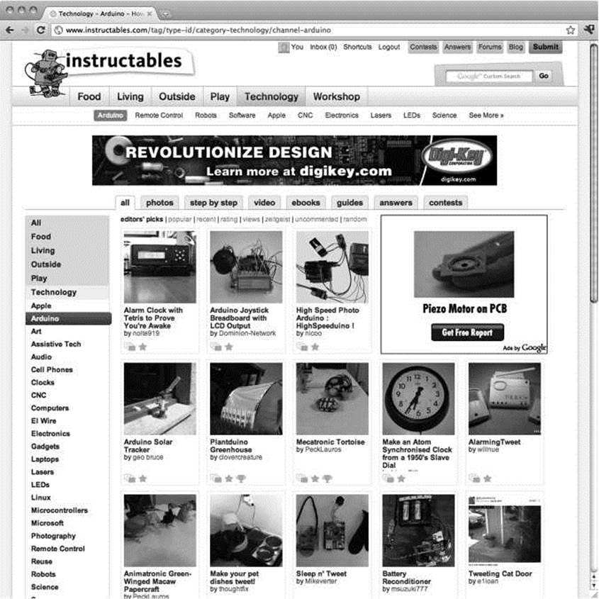
Figure 11-17. Instructables
Not only is Instructables a great place to share your projects, it is also pretty useful for finding answers to some unique problems. Another site for publishing and sharing projects that has gained a lot of ground especially with the 3D-printing crowd is Thingiverse, www.thingiverse.com, shown in Figure 11-18.
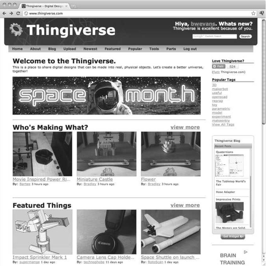
Figure 11-18. Thingiverse
Thingiverse allows you to post a page on anything you make, including images of the finished thing, design files, source code, and instructions for assembly. This allows other users to build a copy of your thing and to even create a derivative of your thing if they make changes or improvements to your design. The centrality of the derivative on Thingiverse is fundamental to a community that encourages friendly reuse and remaking of just about anything that is posted.
If you've developed a neat, simple, modular circuit and some extensible code for the Arduino that can be made into other projects, you should try writing a tutorial for bildr at http://bildr.org (see Figure 11-19).
Home Forum Wiki Code
RSS Twitter Facebook
bildr
•blog
Login / Register
One Wire Digital Temperature. DS18B20 + Arduino
0:0
I know... you are probably thinking “Another Thermometer! How many do you need to cover?" - WeB... All of them. But reaBy, they aB have something different to offer. For instance this guy, the DS18B20, has a unique serial-number sent with it’s data, so if you needed to have 50 of these on one bus, you could and stiB know exactly where the reading came from. And... It’s digital serial bus it uses to transmit the date is just one wire.
For this tutorial we wiB be using just one of them, and our code wiB only support the one. So if you need to read from a few or a lot of these, contact us in the forum and we can help you out. There is also a good amount of code out there for using a bunch of these at once, but no examples of just the one.
Hoolang it up
This is by far one of the more simple digital sensors to hookup. Aside from power and ground, it has a single digital signal pin that we wiB be connecting to digital pin 2 on our arduino. It also requires a 4.7kpull-up resistor between the signal and power pin as shown in the iBustration. (I tried the internal puB-ups on the arduino but it did not work)
; fno DowerL but it
ւ be hooked ud with iust 2 ՛
Figure 11-19. bildr.org
bildr is the place for short and simple tutorials that show how to build the parts that might be used in a larger project. It's a great resource for finding out how to connect a particular device and a little bit of code to get started with it. They are always looking for new writers, so as you learn how to connect new and interesting things to the Arduino, consider writing a tutorial to help others with that same gizmo.
Summary
Well, that pretty much wraps up our suggestions for some ways to continue on with your Arduino knowhow, including some new project ideas, introductions to new programming languages, and a little encouragement for getting involved with the open hardware community. Hopefully, you've got some new ideas for projects that you can't wait to get started on. Or maybe you will pick up a new language now that you've got a handle on this one and introduce your Arduino to new capabilities it never knew
before. Or maybe I'll see that you have contributed to the community in some way, like posting a project that you're working on or by answering someone's question on some forum.
We're not done with the book just quite yet. Up to now, we have really focused on the topic of beginning Arduino programming, leaving the electronics that we use as a secondary focus. For me though, what makes programming microcontrollers way more interesting than programming other things is the way that code can affect physical things—fading lights, changing the speed of motors, and firing off blenders when your cat gets on the counter. To better understand these things, we will finish our book with a review of some basic principals of working with electronics, taking a closer look at various components and what they do, how to read schematics, discussing techniques for prototyping, and a little simple soldering to better stick two things together. Armed with your understanding of Arduino programming and a fundamental grasp of basic electronics, you'll be ready for anything.