Beginning Arduino Programming (Technology in Action) (2011)
Chapter 4. Making Decisions
In the last chapter, we explored variables and how to declare them, their data types, assigning values, and performing simple operations using them. In this chapter, we will put the variables to work with some fundamental structures that the Arduino uses to make decisions and perform repetitive operations. This could include reading a switch or sensor and doing something based on its input, performing one or a set of operations for a defined number of times or until a different condition is met, or performing a range of operations depending on a range of conditions.
Our next project, Tilt Blink, adds a tilt switch to our RGB LED to form the basis for the rest of the chapter's in-depth discussions of the various statements for making decisions, such as the if, for, and switch statements and other control structures. We've also changed our code some, just to make things more interesting.
What's needed for this chapter:
• Arduino Uno
• 5mm RGB LED with common cathode
• Rolling ball tilt switch or other mechanical switch
• 1x 330 ohm , 2x 220 ohm, and 1x 10 kilohm У watt resistor or similar
• Hookup wires
• Solderless breadboard
Project 3: Tilt Blink
For this project, we are building on our 7-Color Blink project from the last chapter with the addition of a simple tilt sensor. Let's say we want to quickly blink through the seven basic colors when our device is tilted or shaken, but otherwise turn off the LEDs when it's left alone. The tilt switch we are using to make this happen is a small metal tube with two wires coming out the bottom. Inside is a small metal ball that, when flat makes contact with the two wires closing the switch, but when tilted, the ball rolls away— opening the switch. This will be our way to turn on and off the RGB LED. Alternatively, any number of mechanical switches could be used instead if you can't find a tilt switch.
Hooking It Up
For this project, we are adding a simple circuit for the tilt switch (or other type of mechanical switch) to work as a very basic sensor. In this circuit, when the switch is open, a resistor connects the input pin to ground, providing a LOW signal. When the switch is closed it creates a connection to +5v, providing a HIGH signal. We will use these two states to light up our LED. Figures 4-1 and 4-2 show how to wire it up.
+5 VDC
SW1
1234
1- RED
2- GROUND
3- BLUE
4- GREEN
PIN 11
LED2 GND
Figure 4-1. Tilt Blink schematic
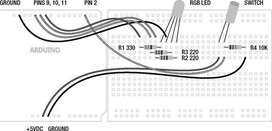
Figure 4-2. Tilt Blink illustration
Uploading the Source Code
In our last project, we managed to cycle through seven different colors with our LED in a fairly simple and straightforward manner. And that's generally a good thing, except when you start to try to do two or more things at once like cycling through different colors all the while waiting for a tilt switch to be triggered. In the last example, it would take 8 seconds to make it through all of the colors once. In that amount of time we could have easily missed a switch being triggered because our code was not smart enough, or fast enough, to do two things at once. In our source code for this project, shown in Listing 41, we have attempted to solve this by speeding things up a bit, reducing our time between readings from 8 seconds to a half of a second. We've also compartmentalized our code a bit more, introducing many of the concepts that I will explain further in this chapter.
Listing 4-1. Tilt Blink Source Code
const int rgb[] = {9,10,11}; const int time = 250; const int switchPin = 2;
void setup() {
for (int i=0; i<3; i++) pinMode(rgb[i], OUTPUT); pinMode(switchPin, INPUT);
}
void loop() { int newPin = 0; int oldPin = 0;
digitalRead(switchPin);
int bouncel delay(25); int bounce2
digitalRead(switchPin);
while ((bounce1 == bounce2) && (bounce1 == LOW)) { oldPin = newPin; newPin++;
if (newPin == 3) newPin = 0;
digitalWrite(rgb[oldPin], HIGH); delay(time);
digitalWrite(rgb[newPin], HIGH); delay(time);
digitalWrite(rgb[oldPin], LOW);
if (newPin == 0) {
for (int i=0; i<3; i++) digitalWrite(rgb[i], HIGH); delay(time);
for (int i=0; i<3; i++) digitalWrite(rgb[i], LOW);
}
bounce1 = digitalRead(switchPin); delay(25);
bounce2 = digitalRead(switchPin);
}
for (int i=0; i<3; i++) digitalWrite(rgb[i], LOW); delay(25);
}
Source Code Summary
This sketch looks dramatically different from our last one, so let's take it one step at a time to see how it works beginning our summary at the top with variable declarations. We start with the following three, constant, global variables that we will use throughout our sketch:
const int rgb[] = {9,10,11}; const int time = 250; const int switchPin = 2;
The variable rgb[] is actually a special type of variable called an array that will be explained fully in Chapter 8. It contains the three pin numbers for our RGB LED (9, 10, 11) and each position in the array can be accessed by an index number (0, 1, 2). The variable time is used for the delay between each color—we speed it up here to make it more interesting. Finally switchPin is the pin that our tilt switch is connected to.
We use our setup() function to set the mode for each of the I/O pins that we are using, as follows:
for (int i=0; i<3; i++) pinMode(rgb[i], OUTPUT); pinMode(switchPin, INpUt);
The first line uses a little trick with a for loop to step through each index of the array to configure each pin as an output. The next line establishes the input pin for our switch.
One of the challenges of quickly stepping through all seven colors is that we need to alternate between one color on, and then two colors on, and then back to one, moving through a specific sequence. For example, if we start with red, then we need to add green to make yellow, and then turn off red to leave green. To keep track of these alternating colors, or pin numbers, we set up two local variables in our loop() function:
int newPin = 0; int oldPin = 0;
We'll come back to these variables in a moment. The next thing we need to do is to read the state of the switch to see if it has been triggered or not. The challenge here is that because switches are mechanical devices, whenever a switch is triggered, the metal contacts inside the switch have a tendency to “bounce,” creating false or multiple triggers. To get around this, we can very quickly read the state of the digital input twice with a short pause between each reading and compare the results. If the two readings are the same, chances are pretty good that the switch has indeed been triggered. If not, it's probably a false reading. This is called debouncing. To do this we use the following:
int bouncel = digitalRead(switchPin); delay(25);
int bounce2 = digitalRead(switchPin);
In this section of code, we declare a variable called bounce1 and assign it the value of the switch reading, pause for a very short amount of time, 25 milliseconds, and then declare a second variable called bounce2 and assign it the value of a second reading. That's just enough time to ensure a good reading from the switch. We can then compare these readings in a while loop:
while ((bounce1 == bounce2) && (bounce1 == LOW)) {
For as long as both readings are the same, and they are both LOW (the tilt switch is normally closed so it only opens, creating a LOW signal in our circuit when the switch is tilted) the following code in the while loop will continuously run. Once the switch has been triggered, we begin the process of quickly blinking through each of the seven colors. To do this we bring back the following two variables:
oldPin = newPin; newPin++;
What these two lines do is to assign the old value of newPin to oldPin and then increment newPin by 1. This way newPin is always one value ahead of oldPin. From the declaration of these two variables earlier, each start at 0, oldPin stays at 0 while newPin becomes 1. These values will be used as the index in the array and correspond to pin numbers for the RGB LED, so index 0 is pin 9, index 1 is pin 10, and index 2 is pin 11. Each time through the loop these numbers will increment by 1. If newPin ever reaches 3, an index that does not exist, this line will reset newPin to the value 0, as follows:
if (newPin == 3) newPin = 0;
This might make more sense when we look at the following business end of this loop:
digitalWrite(rgb[oldPin], HIGH); delay(time);
digitalWrite(rgb[newPin], HIGH); delay(time);
digitalWrite(rgb[oldPin], LOW);
Each time through the while loop, we will start with turning on the old pin, delay, then turn on the new pin, delay, and finally turn off the old pin. This is what will allow us to not only make the primary colors, but also the intermediate colors, as well. The one color that will not work this way is white. To get around that we use the following block of code:
if (newPin == 0) {
for (int i=0; i<3; i++) digitalWrite(rgb[i], HIGH); delay(time);
for (int i=0; i<3; i++) digitalWrite(rgb[i], LOW);
}
This if statement will turn on all of the colors of the LED to make white, delay, and then turn them all off, using that neat little trick from earlier to step through each pin in a for loop. This happens so fast that it simply appears that each color turns on or off at the exact same time.
The last thing to do in our while loop is to check if the state of our switch has changed at all by running our debounce code again, and if the state has changed, the while loop will exit. Finally, the last thing in our sketch is a line to make sure that all of the colors are off if the switch has not been triggered, and then we add a short delay just to make sure our readings stay in line.
Now, much of that may or may not have made a whole lot of sense. Don't worry too much about that for now because we will spend the rest of the chapter trying to explain how these control structures work in much greater depth. You might want to come back to this and see if it makes more sense after reading through the rest of this chapter.
Comparative and Logical Operators
Conditional statements like the for loop and if statement discussed in this chapter use comparison and logical operators to test for conditions. Comparative operators are used to compare the left side of an expression against the right side to produce a value of true or false. With this piece of information, the Arduino can use it to make decisions depending on the type of control structure being used. So if you wanted to test whether or not a variable held a particular value, you might use an expression like the following:
myValue == 5
Here we use the == comparative operator to test if the variable or value on the left of the operator is equal to the variable or value on the right. In this case, the expression would return as true if myValue contained the value 5, and false if it did not. You should note that we use the phrase “is equal to” instead of “equals”. This helps us to differentiate the comparison operator (==) from the assignment operator (=), with the former referred to as “is equal to” and the later “equals”.
Table 4-1 lists other comparative operators that we will discuss in greater depth and provide examples for in this chapter and beyond.
Table 4-1. Comparative Operators
|
Symbol |
Description |
Is true if... |
|
== |
is equal to |
the left side is |
|
!= |
is not equal to |
the left side is |
|
< |
less than |
the left side is |
|
> |
greater than |
the left side is |
|
<= |
less than or equal to |
the left side is |
|
>= |
greater than or equal to |
the left side is |
equal to the right side
not equal to the right side
less than the right side
greater than the right side
less than or equal to the right side
greater than or equal to the right side
Comparative operators work great if needing to compare two values against each other, but you might need to make some more complex logical comparisons. In this way, you could use a logical operator, for example, to make two separate comparisons, and only do something if both comparisons are true. Consider the following example expression:
myValue >= 10 && myValue <= 20
This expression uses the logical and (&&) operator, returning true if and only if the conditional statements on both the left and the right are true. In this case, this statement will be true if myValue contains a value greater than or equal to 10 and less than or equal to 20. This creates a range of numbers between 10 and 20 that could be true.
Conversely, the logical or (||) operator will return a value of true if either of the conditional statements on the left or right is true. Take this following example:
myValue < 10 || myValue > 20
This line would only return true if myValue contained a value that was less than 10 or greater than 20, excluding the values from 10 through 20.
The final logical operator is the not (!) operator. This one is a little different from the others in that it works on only one operand and returns true only if the expression is false. Take the following example:
!myValue
This line will return true only if myValue is false or contains the numerical value of 0.
Comparative and logical operators are going to play a crucial part in the Arduino decision-making process. Table 4-2 provides a quick reference of the logical operators to refer back to.
Table 4-2. Logical Operators
|
Symbol |
Description |
Is true if... |
|
&& |
logical and |
both expressions are true |
|
|| |
logical or |
either expression is true |
|
! |
logical not |
the expression is false |
Control Statements
Up until this chapter, our source code has been relatively straightforward. The Arduino microcontroller reads the lines of code in our sketches from the top of the code until it reaches the end at the bottom, and, when there are no more commands to execute, will bounce back to the top of the loop() function and start over again. The order or direction in which code is executed is called program flow and the ability to alter this order of executing commands is something called flow control.
There are two kinds of statements available in Arduino C for controlling program flow: conditional statements that make decisions based on whether or not a condition is true and iterative statements that perform things a certain number of times or until a condition becomes false. Conditional statements that include the if and switch statements selectively perform certain actions based on the state of a condition. Iterative statements that include the for and while statements are often called loops because, just like our loop() function, they will loop to the beginning of the statement and repeat their code when a condition has been met.
If
The if statement is the simplest of the control structures and is among the most prominent method for Arduino decision making. It will perform a block of code if a specific condition is met. The basic syntax for an if statement looks as follows:
if (condition) { statements
}
Following the keyword if, a pair of parentheses encloses a conditional expression. If we wanted to test a certain variable to see if it is equal to the value 5, we would begin the statement like the following:
if (myValue == 5)
In this example, if myValue is equal to 5, the statement would execute any following simple statement or block of statements enclosed by curly braces. If the condition is not met, in that they return the value false, then the following statement(s) will be ignored and are not executed.
A common use for the if statement is to read the state of a digital pin and perform an action based on its condition. As a hypothetical example, this could look something like the following:
tiltSwitch = digitalRead(switchPin); if (tiltSwitch == HIGH) digitalWrite(13, HIGH);
This is a simple example that reads the value of switchPin assigning that value to the variable tiltSwitch and then tests the condition of tiltSwitch. If tiltSwitch is equal to the constant HIGH, then it will call the digitalWrite() function to change the state of the digital pin 13 to HIGH, which would have the effect of turning on the pin 13 LED on the Arduino interface board. Notice that this is another example of a simple statement that does not require curly braces.
If we wanted the LED to only turn on when the switch is activated and to remain off the rest of the time, we would use an if...else statement. Take the following example:
tiltSwitch = digitalRead(switchPin); if (tiltSwitch == HIGH) digitalWrite(l3, HIGH); else digitalWrite(l3, LOW);
Like the previous example, this statement will turn on the LED if the switch has been activated, however, by using the else keyword it is possible to turn off the LED the rest of the time. Essentially, if the condition is true, only the first statement will be executed and if it is false, only the second statement will be executed. In plain English, this statement would be similar to saying
"If the switch is on then turn on the LED, otherwise turn off the LED.”
So far, our if statements have been checking for a specific condition using the == (is equal to) operator although any of the comparative or logical operators as shown could be used instead. Take for example, the following:
if (myValue >= 10 && myValue <= 20) { statements
}
This if statement will check for a range of values, only executing the following statements if the value of myValue is somewhere between 10 and 20.
if (ImyValue) { statements
}
This sample uses the I (not) operator so that the enclosed statements will only be executed if the variable myValue is false, which also corresponds to 0 or LOW, but we will get to that a little later in the next chapter.
For
The for statement, or for loop, is an iterative statement that allows the Arduino to repeatedly execute lines of code in a loop a specified number of times. What makes the for loop unique is that it is based on a counter, or a specific variable that is incremented each time the loop is repeated. This counter is even quite useful, as the counter itself can be used just like any other variable by statements that reside inside the loop, as you will see in later examples. The basic syntax of a for loop follows:
for (declaration; condition; increment) { statements
}
The for loop begins with three statements that include: variable declaration, conditional statement, and incremental statement. Of these, the first is the counter variable declaration or initialization and is run only once the first time through the loop. The second statement is the conditional statement using comparative operators just like those found in the if statement and is tested each time through the loop.
If the condition remains true, the following code bracketed by the curly braces will be executed. If, however, the condition returns false, the for loop will end. The third and final statement increments the counter variable each time the enclosed block of code is executed.
Let's say we wanted to blink an LED five times quickly, we could use a for loop similar to the following:
for (int i = 0; i < 5; i++) { digitalWrite(l3, HIGH); delay(250);
digitalWrite(13, LOW); delay(250);
}
In this sample code, the first time through the for loop, we declare an integer type variable to serve as our index or counter and assign it the value 0 in this statement:
int i = 0;
Each time through the loop, the conditional statement will be checked to see if the condition remains true. Take, for example, the following:
i < 5;
In this statement as long as i is less than 5, the enclosed statements will be executed, turning on pin 13, waiting for 250 milliseconds, turning pin 13 off, then waiting another 250 milliseconds.
Each time through the loop, after all of the statements within the curly braces have been executed, the variable i is incremented, in an increment statement:
i++;
In this case we add 1 to the value of i and reassign this new value back to i so that each time through the loop i increases by 1. Remember the compound operator i++ is functionally identical to i = i + 1. In this way, i starts at 0 the first time through the loop, incrementing 5 times each time through the loop until its value is no longer less than 5, consequently ending the loop. In our project code, an example of the for loop in action includes the following example:
for (int i=0; i<3; i++) pinMode(rgb[i], OUTPUT);
Here, we are using a local variable i declared inside the loop to be used as a counter and assigned the value 0. For as long as i remains less than 3, expressed in the conditional statement i<3;, the code following the for statement will be executed. The for loop will then repeat three times, and each time the pinMode () function will be executed, setting a pin, as defined by the rgb [ ] array, as an output. Because we only needed a single simple statement to be executed, the curly braces are not required.
You can also see that we have used the counter i to increment the position of the array rgb[] being referenced. After that statement has been executed, the counter i will be incremented by one. Once i has reached the value 3, the for loop will terminate and proceed with the standard program flow to the following line of code.
While
The for statement is fairly common to Arduino programmers, but there are other ways to structure iterative loops. Where the if statement executed a statement once if a condition was met, and the for loop cycles through a specified number of times, the while statement, or while loop, is used to continuously execute a statement so long as the condition remains true. The basic syntax of a while statement looks like the following:
while (condition) { statements
}
Using the while statement, we could rewrite the previous for loop example to blink an LED five times in the following manner:
int i = 0; while (i < 5) { digitalWrite(13, HIGH); delay(250);
digitalWrite(13, LOW);
delay(250);
i++:
}
The first line, int i = 0; declares the index variable and assigns the value 0. The program flow reaches the while statement and compares the value 5 to the variable i, with the first time evaluating as true. The enclosed statements are then executed, which includes the line i++; used to increment the value of i at the end of the block of code.
When the end of the statements is reached, it loops back to the conditional statement of the while loop and if the condition remains true, the following statements are executed all over again. If, however, the condition is false, then the while loop ends and control passes to the following statements in the program.
So with the for loop, why would you need the while loop? If the previous example was all you were ever going to do with it, then no there is really not much use for it. However, if you think of the while statement more as a continuous if statement, then it becomes quite useful in the right situation. From our project code, we needed to do one thing over and over again while the switch remained triggered and to prevent the continuation of normal program flow until that condition is no longer met. In other words, as long as the switch was triggered in our project example, we wanted to continue to cycle through each of the seven colors until such time as the switch was no longer triggered.
A simpler way to write this code would be something like the following:
while (digitalRead(2) == HIGH) digitalWrite(13, HIGH);
In this example, for as long as the digital input on pin 2 is equal to HIGH, if for example a switch has been activated and is on, then the while loop will continue to keep pin 13 on, or HIGH, and will never exit the loop. Only when the conditional expression digitalRead(2) == HIGH returns false will the next following line of code be executed.
Do
Like the for statement, the while statement evaluates its condition before executing its block of code so that if the condition is not met, its code will never run. Sometimes it would be nice to always run the enclosed code at least once before evaluating its condition and for that we would use the do statement, or do loop. The do loop is like a modified while statement in that it executes a line or lines of code and then tests for a condition at the end of the loop rather than the beginning before deciding to loop to the beginning again or not. The following is the basic syntax for a do loop:
do {
statements } while (condition);
Rethinking the last code sample, we might want to make sure that the LED is off if the switch is off before continuing on with the rest of our sketch. Using the do...while loop we could write the statement like the following:
do digitalWrite(l3, LOW); while (digitalRead(2) == LOW);
In this sample, no matter the condition, the do statement will turn off the LED on pin 13 at least once and then test the input pin 2. While the expression digitalRead(2) == LOW remains true, the do loop will repeat infinitely, keeping the LED off. When the condition is no longer true, the do loop will exit and return to normal program flow.
Switch
The switch statement is like a really nifty version of the if statement in that it can execute one or more blocks of code, depending on a range of conditions. Basically, the switch statement compares the value of an expression against a list of cases executing whatever code begins after that case when a match is found. switch is a fairly powerful and complex control structure so we will only scratch the surface here, revisiting it in later chapters when we can better apply it. The basic syntax of the switch statement follows:
switch (expression) { case constant: statements; case constant: statements; default: statements;
}
The number of cases can be as many as you need (or have the memory for), but each one should have a unique constant or single-byte character following it—variables like myValue are not allowed as a case. After the colon that defines the case, we can have a block of code that is executed when that case is true. The default case allows for code to be executed when a specific case has not been previously specified.
To get a better idea for how the switch statement works, let's say we want to modify the early LED blink sketch using the switch statement so that when the tilt switch is activated, the LED will stay on rather than blink. To do that we could use the following code sample:
switch (digitalRead(2)) { case 0:
digitalWrite(13, LOW); delay(1000); case 1:
digitalWrite(13, HIGH); delay(1000);
}
Beginning with the expression following the switch statement, we will read the state of the digital input pin 2. If the tilt switch is activated then the pin will read as HIGH, which if you remember is basically equal to the value 1, and the code for case 1 will be executed. If the tilt switch is not activated it will read as LOW or 0, so the code beginning with case 0 will be executed until the end of the switch statement. This will also include the code following case 1 because the normal program flow did not reach the closing curly brace yet.
What this means is that, assuming the switch statement is the only code in our loop() function, when the tilt switch is off, the LED will blink on and off every 1 second but when the tilt switch is on, the LED will stay on and not turn off again until the tilt switch is turned off.
Break
The break statement can be used inside other control statements to immediately end the loop or statement. If we borrow our five-blink sample from before, we could add an if statement followed by the break statement to exit out of the loop if a switch is activated. This would look like the following:
for (int i = 0; i < 5; i++) { if (digitalRead(2) == HiGh) break; digitalWrite(13, HlGH); delay(250);
digitalWrite(13, LOW); delay(250);
}
Normally, in this example the for loop will complete its cycle five times before continuing on with the rest of the program. The additional line if (digitalRead(2) == HIGH) break; will check the status of pin 2 and if it is equal to HIGH, from a switch being activated, the break statement will cause the for loop to quit immediately and program control will resume with the next line of code after the for loop.
To go back to the earlier example for the switch statement, if rather than the LED blinking when the switch is LOW, we could use the break statement to break out of the switch statement by adding the break keyword at the end of case 0, like in the following modified example:
switch (digitalRead(2)) { case 0:
digitalWrite(13, LOW); delay(1000); break; case 1:
digitalWrite(13, HIGH); delay(1000);
}
Using break, when the code for case 0 has been executed, the statement is broken and program flow continues with the code after the end of the switch statement. With the modified code, we should be left with an LED that is on when the switch is on and off when the switch is off. The added bonus with the break statement is that it gives us the ability to have a loop that is conditional on multiple factors or behaviors. This is also effectively a way to end any loop structure through external sources.
Continue
The continue statement does not exit or quit an iterative loop like break does, but rather it skips over any remaining statements inside the loop and goes on to the next repetition of the loop. The continue statement only works on iterative statements like the for, while, and do loops and can be used among other things to skip odd or even numbers in a for loop. For example, if we had five separate LEDs connected to the Arduino on pins 9 through 13 and wanted to turn on and off only the odd number LEDs in sequence, we could use something like the following:
for (int i = 9; i <= 13; i++) { if (i % 2 == 0) continue; digitalWrite(i, HIGH); delay(500); digitalWrite(i, LOW); delay(500);
}
In the line of code, if (i % 2 == 0) continue;, we have added a conditional test based on the modulus operator in i % 2 so that if the number in the loop is an even number, it will evenly divide by 2 leaving a 0 remainder. If that condition is true, the continue statement will skip any further instructions inside of the loop and head back to the increment component of the for statement and resume normal operation.
In this example we also started our for loop with the value 9 (i = 9), incrementing i by 1 each time through the loop (i++), so long as i is less than or equal to 13 (i <= 13) for a total of five possible iterations. We are also using the indexing variable to correspond to a specific digital pin by using i in the statements like digitalWrite(i, HIGH);. In the end, the even numbers will be ignored and the LEDs connected to pins 9, 11, and 13 will turn on and off in sequence.
Summary
In this chapter, we explored all manner of ways in which the Arduino can alter the standard top-to-bottom program flow using various methods to make decisions and perform repetitive actions. You should have a basic understanding of how to make decisions using conditional statements and how to perform repetitive tasks in iterative statements, or loops. Of course, we will continue to work with these concepts in later discussions, building out from our foundational understanding of how we can structure Arduino sketches. But for now, that about wraps up the discussion of the generally more C-based structural programming syntax.
From here, we will discover more of the uniquely Arduino aspects of programming the Arduino microcontroller board that specifically relate to sensing and controlling the physical world. These are the parts of the Arduino library that make Arduino C unique. This is going to be the really fun stuff.