Beginning Arduino Programming (Technology in Action) (2011)
Chapter 6. Analog In, Analog Out
The Arduino interface board, just like most other computers, is a digital system that operates on binary values: 1 and 0, on and off, true and false. What if we wanted to know not just whether it was hot or cold outside but rather how hot or cold it was? Or instead of turning an LED on or off, maybe we want to dim or even fade an LED? To do this we need to either convert an analog reading into something that the Arduino can understand or, vice versa, approximate an analog output using digital signals. Where a digital signal has two possible states, an analog signal has many. Because we are dealing with electrical signals, digital states on the Arduino are usually considered to be 0v for LOW or off and +5v for HIGH or on. Analog signals on the other hand might represent any voltage between 0 and +5 volts, infinitely more than just on and off.
This chapter will specifically address the available hardware and the functions that we need to use them, in order to read, interpret, and output analog signals. We will discuss how a digital microcontroller can use both analog and pseudo-analog signals—pseudo-analog signals are signals simulated by digital means—converting and manipulating these signals as needed. We will look at a project called Telematic Breath that takes advantage of both reading and writing analog signals, followed by a more in-depth discussion of the various analog functions and how they work. We will also look at a way to “see” the analog input as the Arduino sees it, wrapping up the chapter with methods for mapping these values to more usable forms.
What's needed for this chapter:
• Arduino Uno
• Modern Device MD0550 wind sensor
• 2N2222 or 2N3904 NPN transistor or similar
• 5 volt DC brushless fan 50mm x 50mm or similar
• 10 kilohm CdS photocell or similar
• 10 kilohm and 1 kilohm У watt resistors
• Hookup wires
• Solderless breadboard
Analog Demystified
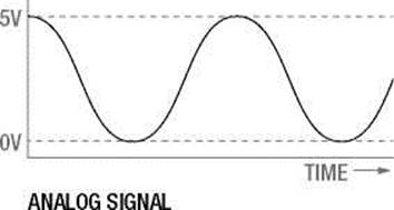
To get our heads around the concept of what analog is, we should compare the difference between analog and digital signals beginning with Figure 6-1.
5V
0V
TIME-
DIGITAL SIGNAL Figure 6-1. Digital versus analog signals
Looking at these two graphs that show the effect of the different signals types over time, you can see that where a digital signal abruptly shifts from high to low, an analog signal can gradually move through a multitude of steps in between these two extremes. This varying, or analog signal, is what we can use to determine how cold it is, how much pressure is being exerted, or to change the brightness of a light or the speed of a motor. In order for the digital microcontroller that likes 1s and 0s to be able to input and output analog signals we need to use some additional hardware built onto the chip to convert or interpret these signals for us.
In order to receive an analog input, we need to use the microcontroller's analog to digital converter, usually called an A/D converter or ADC, to convert a continuous analog voltage applied to one of the analog pins into a digital integer proportional to the amount of voltage at that pin. This is a specialized bit of hardware that is connected to 6 of Arduino's general I/O pins, marked on the board as A0–A5. The Arduino ADC has a 10-bit resolution, meaning that it will return a linear value from 0 to1023 corresponding to 0v and +5v respectively. With this resolution, the Arduino ADC can read levels of voltage down to 4.88 millivolts per level. Keep in mind, however, that where an analog signal is a continuous signal, the ADC will only take a single reading at the very instant that the function is called.
Because it is a digital device, the Arduino is actually incapable of providing a true analog output. Instead, it approximates an analog signal by turning on and off a pin very quickly in a process called pulse width modulation (PWM). This happens so fast it is nearly imperceptible to the eye, instead looking like a dim LED or a slow motor. The hardware that does this is connected to pins 3, 5, 6, 9, 10, and 11 on the Arduino Uno and has an 8-bit resolution, meaning that values between 0 and 255 will simulate voltages between 0v and +5v. While not a smooth continuous analog signal, by alternating the amount of time that the pin is on, or its pulse width, in relation to the time off, it will emulate an analog signal. The average voltage created by quickly alternating between on and off is called the duty cycle as illustrated in Figure 6-2.
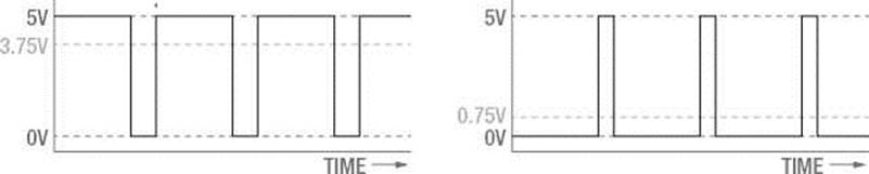
75% DUTY CYCLE FOR 3.75V 15% DUTY CYCLE FOR 0.75V
Figure 6-2. Pulse width modulation duty cycle
Figure 6-2 shows how a PWM signal that is on, or +5v, for 75% of the time and off, or 0v, for 25% will simulate an analog voltage of +3.75v. This would be referred to as a 75% duty cycle. Likewise, a duty cycle of 15%, where the pin is on for 15% of the time and off 85% of the time, would result in only an average of +0.75v. This is how we can use PWM to give an LED the appearance of fading or with the right hardware to change the speed of a motor. Now that we have a handle on how analog works on the Arduino, let's look at our next project.
Project 5: Telematic Breath
In our fifth project, we will sense and re-create or “broadcast” a breath or gentle breeze from one location to another using a simple wind sensor and a small fan. Breathe on the sensor and the fan will spin at a speed that correlates to the force of your breath. In this way, applying the data from an analog sensor to the speed of a fan will provide a very tangible experience of transmitting data from one source to another.
Hooking It Up
While the hardware is a little more complex than previous projects, it's not really all that bad, with a total of four components. We have specified a very particular sensor and fan at the beginning of this chapter to complete this project, although just about any analog sensor could be used in place of the wind sensor and about any other DC fan, motor, solenoid, or other actuator could be used to substitute the fan. Likewise you might change out the transistor for another switching device like a relay or MOSFET, detailed later in Chapters 11 and 12.
This particular wind sensor is a low-cost thermal anemometer developed by Paul Badger at Modern Device to measure wind speed. Specifically, it measures the electricity needed to maintain a specific temperature on a heating element as the wind changes. This sensor is remarkably sensitive and can detect the slightest breath. We will couple this with a fan to re-create the wind speed input by controlling the speed of the fan through PWM.
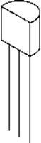
The fan we chose will run on +5v DC, but it exceeds the current available to the Arduino's output pins, so to power it safely, we need to use a small transistor to switch the bigger load. The transistor we are using is the 2N3904, although the 2N2222 is pin compatible and you could even substitute any of a number of other similar devices. The 2N3904 has 3 pins labeled e, b, and c—for emitter, base, and collector respectively. These names refer to what each pin does: emitter is connected to ground; collector to the negative side of the load, in this case the black wire on the fan; and base connects to a series resistor and to the PWM pin on the Arduino.
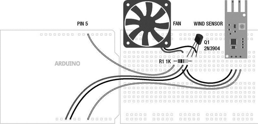
It is possible to use a higher voltage fan, say +12v DC, using a transistor to switch it on and off. To do this you need to connect a higher voltage power supply into your Arduino and instead of connecting the positive or red wire to +5v, you would connect it to a pin on the Arduino interface board labeled Vin. Just be sure to be careful as you wire up the circuit shown in Figures 6-3 and 6-4, taking it slow and doublechecking everything to make sure you get the pins correct on the sensor and the transistor, and you will be fine.
+5 VDC
(^FAN^)
R1 1K
PIN 5
b
c
e
GND
Q1 2N3904
ebc
PIN A0 +5 VDC
>
![]()
GND
OUT +5 VDC GND
WIND SENSOR
Figure 6-3. Telematic Breath schematic
+5VDC GND PIN A0
Figure 6-4. Telematic Breath illustration
Uploading the Source Code
After the crazy source code in the last chapter, this sketch will seem tame in comparison. Although while there is not much length to the code, there are a lot of new things going on that we will spend the rest of the chapter trying to explain. So let's get the circuit wired up, upload the source code in Listing 6-1, and see what it does.
Listing 6-1. Telematic Breath Source Code
const int fanPin = 5; const int sensorPin = A0;
const int minReading = 25; const int maxReading = 400; const int fanStart = 100;
int analogValue = 0;
void setup() {
Serial.begin(9600);
}
void loop() {
analogValue = analogRead(sensorPin);
analogValue = constrain(analogValue, minReading, maxReading); analogValue = map(analogValue, minReading, maxReading, 0, 255);
Serial.print("analog value = " ); Serial.println(analogValue, DEC);
if ((analogValue > minReading) && (analogValue < fanStart))
analogWrite(fanPin, fanStart);
else analogWrite(fanPin, analogValue);
delay(250);
}
Source Code Summary
Like nearly all of our sketches, we begin this one with a declaration of variables for the pins that we will use, giving them descriptive names. In this case, fanPin and sensorPin.
const int fanPin = 5; const int sensorPin = A0;
Our next block of variables pertain to some general thresholds that relate to our sensor readings and what it takes to get the fan spinning.
const int minReading = 25; const int maxReading = 400; const int fanStart = 100;
The first variable minReading can be adjusted to reflect the minimum reading that our sensor is providing. Likewise, maxReading is used for the same purpose on the other end of the spectrum. This is, after all, a telematic breath, not telematic gale-force wind. To make the sensor even more sensitive, you might try a smaller value for maxReading, like 200. The last variable, fanStart, is the minimum value that it takes to get our particular fan up and spinning. Yours may be different.
int analogValue = 0;
Our last variable is the container we will use to store and manipulate our analog value obtained from reading our analog input pin.
void setup() {
Serial.begin(9600);
}
The setup() function is a little sparse in this sketch. I think I can hear you now: “Hey, wait, isn't something missing?” The short answer is not really, because the analog functions make use of very specific hardware in the Arduino microcontroller, there is no need to set them up using the pinMode() function inside our setup() function. If we try to send an analog signal to a pin that isn't made for it, it simply won't work exactly as expected. So then all we are left with is a function that begins a communication protocol that we can use to let the Arduino talk to us.
analogValue = analogRead(sensorPin);
analogValue = constrain(analogValue, minReading, maxReading); analogValue = map(analogValue, minReading, maxReading, 0, 255);
The first three lines of the loop() function are where the magic happens in this sketch. The first line obtains a numerical value from the analog input pin correlating to the voltage our sensor is putting out, which should indicate a general presence of a breath. The second line lobs off unusable values at either
end of the spectrum that don't really work for us. In other words, this line limits our activity to the “sweet spot” of the sensor, making it as sensitive as we can get it to a gentle breeze. The third line takes this larger value and remaps it to a more useable range for output to our fan.
Serial.print("analog value = " );
Serial.println(analogValue, DEC);
These two lines can be used to see what values we are working with using something called the Serial Monitor, explained in more detail later in this chapter. Seeing these values is helpful in adjusting the thresholds defined at the beginning of the sketch.
if (analogValue > minReading && analogValue < fanStart)
analogWrite(fanPin, fanStart);
else analogWrite(fanPin, analogValue);
Now we reach the business end of the sketch—the part that actually does something. Our fan needs a little kick to get it going at first, so the first line checks to see if we have an analog value that we should do something with, but that might be too low for the fan to work with. In our case, we found that the value 100 is about the lowest number to guarantee that the fan would spin. So if that's true, we will send the minimum number to start the fan out to the output pin.
Otherwise, if the value is greater than or less than our fanStart and minReading values, we will send that value straight out to the output pin. If it's a small number, the fan will most likely not spin. If it's a bigger number, it will spin with greater speed up until it hits the ceiling at 255, which is full on.
delay(250);
Finally, our last line of code ends with a simple delay() just to slow things down some. Basically, it takes a little bit of time to get the fan up to speed, so a quarter-second pause is good for that. Now what does it all mean?
Analog Functions
The analog functions are a little different from the digital ones. First, as we discussed earlier, they do not need to be set up using pinMode() beforehand. Second, we are dealing with integer numbers that range from 0 to 255 or 0 to 1023, rather than digital states like HIGH and LOW, so we need to keep that in mind while working with them. So anyway, let's proceed onward with a discussion of the analog functions.
analogReadO
The counterpart to the digitalRead() function, analogRead() is equally as simple at first. Its syntax follows:
analogRead(pin)
When we call this function, we need to specify the analog pin that we are reading data from, in the format of A0–A5. The “A” is placed in front of the pin number to remind us that we are using one of the analog input pins, also marked on the board A0–A5. The reading returns a 10-bit value with a range of integers from 0 to1023 corresponding to the input voltage on the pin.
Also like the digitalRead() function, what we do with this value depends on the context in which we use the function. This includes assigning the reading to a variable to be used later in the code or to use the function in place of a variable. A common usage of this function to assign a value to a variable would appear as follows:
sensorValue = analogRead(Ao);
Or we might use the function inside another. Say for instance, we wanted our pin 13 LED to blink slowly when it was dark and quickly when there was light. With a light sensor connected to pin A0, our code could look as follows:
delay(analogRead(Ao));
Here we will delay for the amount of time as specified by the integer received from analog input pin A0 in an amount from 0 to a little over 1 second. To extrapolate this into a full code example, have a look at Listing 6-2.
Listing 6-2. analogReadO Example
int analogValue = 0; int ledPin = 13;
void setup() {
pinMode(ledPin, OUTPUT);
}
void loop() {
analogValue = analogRead(A0); digitalWrite(ledPin, HIGH); delay(analogValue); digitalWrite(ledPin, LOW); delay(analogValue);
}
This is the basic blink sketch, except now the LED will blink slowly when an analog sensor provides a low-voltage reading and blink quickly when the sensor provides a higher voltage reading. This works by adding an analogRead() statement that assigns an analog value to the variable analogValue that we use as a length of time in the delay() function. What analog sensor is used for in this example is up to you, but our wind sensor from our project would work great. So, now that we can read these values, let's look at how can we output analog values.
analogWriteO
The function analogWrite() will allow us to access the pulse width modulation hardware on the Arduino microcontroller. The basic syntax for this function follows:
analogWrite(pin, duty cycle)
In using this function we need to give it two pieces of information. The first is the pin number, which can only include one of the following pins on the Arduino Uno: 3, 5, 6, 9, 10, and 11. These are marked as PWM on the interface board. Other versions of the Arduino may have fewer or more PWM pins available, so double-check your hardware's documentation. The second bit of information is the duty cycle expressed as an 8-bit numerical integer ranging between the values of 0 and 255. The value 0 corresponds to off or 0% duty cycle and 255 is basically full on or 100% duty cycle. Any value in between these two endpoints provides a corresponding duty cycle approximating an analog output.
It is a common practice to express the duty cycle value using a variable instead of a constant value. One way that we could do this would be to use a for loop, as in the following code sample:
for (int i=0; i<=255; i+=5) { analogWrite(5, i); delay(20);
}
This sample code uses a for loop to increment a counter, i, in steps of five beginning with 0 and ending with 255. This value expressed as a variable is then output to PWM pin 5 using analogWrite() followed by a brief 20-millisecond delay. If connected to an LED, this would have the effect of starting with the LED off and gradually increasing brightness until the LED was at full brightness. Likewise, if we used our fan circuit, the fan would start at off and increase in speed until it is spinning at full speed.
We could even combine analog output with analog input, as in the following simple sketch in Listing 6-3.
Listing 6-3. analogWriteO Example
int analogValue = 0; int ledPin = 5;
void setup() {
}
void loop() {
analogValue = analogRead(A0) / 4; analogWrite(ledPin, analogValue); delay(20);
}
This simple little sketch is the most basic form of our source code for the project, although if you try it you'll see it doesn't work quite as well. This code simply takes an analog reading and routes that value to an analog output. Again, there are no statements needed in the setup() function because we are using only analog functions.
One challenge that we face when using a value from an analog input and sending it to an analog output, is that the analogRead() function returns a value in the range of 0 to 1023, while analogWrite() only works with values in the range of 0 to 255. To get around this, when assigning the value to the variable analogValue in the first line of this most recent loop() function, we take the reading from analog pin A0 and divide this by 4 before assigning to our variable. All should work fine because 1024, the total number of possible values in a 10-bit reading, divided by 4 will result in 255, which is the maximum number of values that we can use in the 8-bit PWM function.
Now depending on the sensor we are using on our analog input, this may not result in either the most accurate or the prettiest results. To fix this, we will need to make use of some techniques and functions, some of which were used in our project earlier, to find out what our readings actually are and increase their accuracy, beginning with the next analog function and proceeding on through the rest of the chapter.
analogReferenceO
By using the analogRead() function, the Arduino assumes a voltage range of between 0v and +5v. Increasingly though, more and more sensors are using lower operating voltages from +3.3v to as low as +1.8v, and as a result, will only return values up to their maximum operating voltages. The Arduino interface board, however, has a convenient pin called AREF located near digital pin 13 along with a function called analogReference() to give the Arduino's ADC a reference voltage other than +5v. This function will effectively increase the resolution available to analog inputs that operate at some other range of lower voltages below +5v. The syntax for this function follows.
analogReference(type)
The function is only called once in a sketch, but must be declared before analogRead() is used for the first time, making it a suitable candidate for placing in the setup() function. The type specified relates to the kind of reference voltage that we want to use. There are three possible reference voltage types on the Arduino Uno to be used for analogReference(), as listed in Table 6-1.
Table 6-1. Analog Reference Types
Type Description
INTERNAL Selects an internal reference voltage of+1.1v
EXTERNAL Selects the external voltage reference connected to the AREF pin
DEFAULT Returns to the default internal +5v voltage reference
While there are many reasons and methods for using a different voltage reference, many of these get very complex very quickly. The one we are most interested in providing is an external +3.3v reference when we use an accelerometer sensor to detect movement, discussed in greater detail in a later chapter. In order to get accurate readings from this sensor, we will make the following statement once at the beginning of our source code:
analogReference(EXTERNAL);
We will then need to connect the AREF pin to the output pin labeled 3.3V using a jumper wire. This will use the Arduino's Uno secondary onboard voltage regulator to provide an accurate external analog reference of +3.3v. With this setup, it is important to call the analogReference() function before the analogRead() function, or it is possible to short the internal and external voltages—perhaps damaging the microcontroller. Finally, it is also important to remember to never connect the AREF pin to a voltage source greater than +5v because it could also damage the microcontroller.
Analog Serial Monitor
So far, we have made the general assumption that the readings we are receiving from the analog input pins are providing a range of values from 0 to1023, but this is rarely the case, as you can see in our opening project's source code. The reason for this is that every sensor is a little different and will provide a varying range of voltages depending on what they are sensing. In order to better understand the range of values that a particular sensor is providing, we need to create a sketch to give us some visual representation of the values reported by the ADC. Before getting to that, let's back up again and look at a simpler analog sensor, as shown in Figures 6-5 and 6-6.
+5 VDC
-//
R1 PHOTOCELL
PIN A0 I >֊
R2 10K
GND
Figure 6-5. Photocell schematic
R1 PHOTOCELL
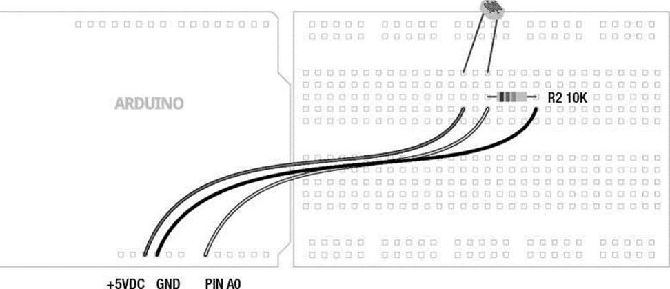
Figure 6-6. Photocell illustration
This schematic uses a variable resistor known as a photocell or light dependant resistor that changes its resistance based on how much or how little light reaches it. Photocells will have a maximum specified resistance for its darkness state and a minimum resistance at full light. For best results, the pull down resistor should match the maximum resistance of the photocell, although this is not mission critical. With this simple schematic wired up, we can use it to sense how light or dark it is in our environment. The question remains, how do we know what range of values our little light sensor is giving us?
Reading Analog Values
To find a solution to this problem, we can write a little code to read the values coming from the microcontroller's analog inputs, using several new functions that are part of the Serial library, itself part of the standard built-in Arduino library. Serial is used by two digital devices to talk to each other and is loosely related to a collection of communication protocols that includes USB. We've actually been using serial communications since the very beginning to upload our source code to the Arduino interface board. Now, using the following code in Listing 6-4, we can use the Serial Monitor included in the Arduino programming environment to actually “see” the values that the ADC is reading.
Listing 6-4. Analog Serial Monitor
const int analogPin = A0; int analogValue = 0;
void setup() {
Serial.begin(9600);
}
void loop() {
analogValue = analogRead(analogPin);
Serial.print("analog value = " );
Serial.println(analogValue, DEC); delay(125);
}
This little sketch borrows quite a bit from our project sketch from before. It will read the value from analog pin A0 and send that value back to our computer using some of the functions that are a part of the Serial library. In order to see what the Arduino has to say, we need to use the Arduino Serial Monitor to listen to the interface board.
Using the Serial Monitor
The Serial Monitor is accessed through the button at the far right of the toolbar, as shown in Figure 6-7.
analog_serial_monitor | Arduino 1.0-betal
opn
Serial V
-
I anaic*g_senai_roni։or ^
const int onalogPin = Д0; int analogValue = 0j
void setupQ •{
Ser i al.beg i n(9600);
}
void loop() £
analogValue = analogPead(analogPin); Serial.print("analog value = " ); Serial.printlri(analogValue, DEC); del ay(125);
>
|
Done uploading. |
|
|
Binary sketch size: 260+ bytes (of a 32256 byte maximum) |
|
|
7 |
Figure 6-7. Accessing the Serial Monitor
After clicking the Serial Monitor button, a new window will open and begin displaying anything that it happens to be receiving from the serial connection to the Arduino interface board, as shown in Figure 6-8.
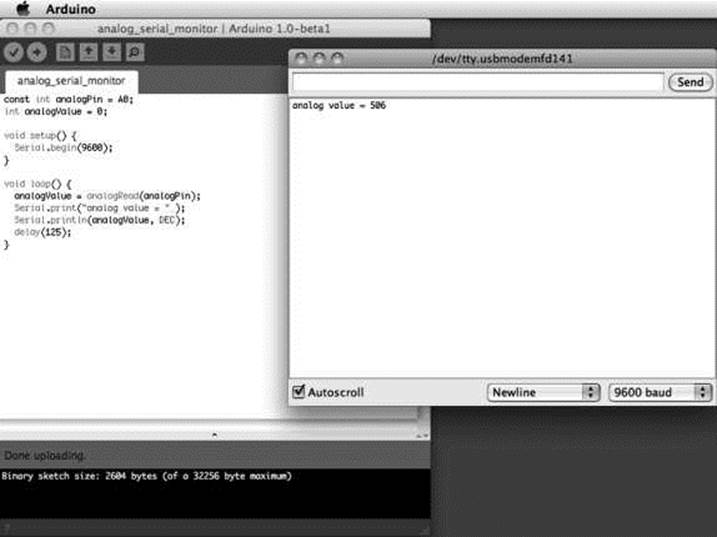
Figure 6-8. Serial Monitor window
Inside the Serial Monitor window, we have a large central white space that displays whatever information it receives from the serial port. We also have a text entry area at the top that would allow us to send data out to a serial device. Along the bottom of the window is a check box to enable the Autoscroll feature, an option for the end-of-line character when sending data from the Serial Monitor, and a setting for the speed of the communications between the two serial devices. While we will discuss serial communications in much greater depth in Chapter 10, now that we have the code uploaded to the interface board, and the Serial Monitor is open, let's briefly look at how our code works.
How It Works
To get the Serial library working with the Arduino interface board, and for it to send data through the hardware serial port, we need to first establish the communications speed between the two devices using the Serial.begin() function. This is generally done inside the setup() function, as was shown in our example code with the following line:
Serial.begin(9600);
Here, we tell the Arduino board at what speed to establish communications; in this case, our communication speed has been set to 9600 bits per second (bps or baud), a fairly common communication speed for these purposes. Basically, this helps the two digital devices agree on how fast they are going to talk to one another and this matching speed setting should also be selected in the Serial Monitor.
The text in the main window in Figure 6-8 that displays “analog value = 506” is created by the following two lines of code in the loop() function:
Serial.print("analog value = " );
Serial.println(analogValue, DEC);
The first line uses the Serial.print() function to tell the Arduino to send down the serial connection the characters "analog value = ” with the double quotations signifying that the string of text should be displayed exactly as written. The second line uses the function Serial.println(), which is very similar to the first, but inserts a line return after it has sent its information so that the next time we send up a value it will start on the next line. This line will display the current value of the variable analogValue in decimal format (DEC).
That's about all there is to this simple little sketch. Now, with an analog sensor wired up to pin A0, the source code uploaded to the Arduino, and the Serial Monitor up and running, we should see a long list of analog values being updated every eighth of a second. This is pretty useful for what we are going to do with these values next.
Mapping Values
Once we see what kinds of values our analog sensor can give us, we can then decide what to do with those numbers. Sometimes we might want to drive a PWM pin using the analog input and so will need to change from a 10-bit value to an 8-bit one. Maybe instead of receiving values that we think we should get, like 0 to 1023, we get something more like 12 for the lowest number and 861 for the highest. It's even possible that although we have all these numbers, all we want to do are a few simple things depending on certain thresholds being reached. To make these unwieldy numbers more manageable, we can use several Arduino functions to map the values we get to the values that we want. Let's keep the photocell wired up and look at these functions in more detail.
map()
Previously, to convert from a 10-bit value to an 8-bit one, we simply divided the analog reading by 4 and applied that value to our analog output. An alternative method would be to use the map() function, which appropriately enough, is one of the more useful functions for mapping sensor values. There are several ways that it can be used, but let's look at its syntax first.
map(value, fromLow, fromHigh, toLow, toHigh)
The way it works is that we pass the function a total of five values, beginning by first defining the value that we want to map. This is most often a variable, but could also be a call to another function. It should be a whole number integer value, as floating-point math is ignored after the decimal point. The second and third values are the low and high values that we are beginning with expressed as constants or variables. This is where the Analog Serial Monitor comes in handy, allowing us to better plan for the values coming from our sensors. Finally, the fourth and fifth values are the new low and high values that we want to map the old values to. A good example of this is using map() to convert a 10-bit reading to an 8-bit value, as follows:
analogValue = map(analogValue, 0, 1023, 0, 255);
This statement will take the value from the variable analogValue with expected values that begin at 0 and go up to a maximum of 1023, and map these values to the new values of 0 to 255. This line effectively converts a range of values from 0 to1023 to 0 to 255. That's pretty handy for driving an analog output with an analog input.
Another thing that comes up frequently is the need to reverse a range of values. For example, using the code in Listing 6-3, the LED gets brighter when the light in the room is brighter. What if we wanted the LED to get brighter when it actually gets darker in the room? To do this we would need to reverse the range of values so that instead of outputting 0–255 we would flip it to 255–0. The map() function can be used to do exactly that.
analogValue = map(analogValue, 0, 1023, 255, 0);
By flipping the last two values, we are functionally flipping the values that we plan to use from the analog input. We can also use the map() function to set up ranges or thresholds of values that can trigger different events. This works well with the switch statement, just like the following code fragment:
analogValue = map(analogRead(analogPin), 0, 1023, 1, 3); switch (analogValue) { case 1:
;
case 2:
;
case 3:
;
}
In this fragment, we are taking an analog reading and boiling it down to three possible states. Think of it as near, not too far, and far away; cold, warm, and too hot; dark, just right, and bright. What we do with those three states, I leave up to you.
constraint)
While the map() function is useful for changing the start and end values of a variable, it does not limit them to only those values. Leaving values outside of the map() function might be handy if we only want to map a small part of a range of values, but leave the rest of the possible values intact. If, though, we wanted to force the values to a very specific, limited range instead, we could use the constrain() function. The syntax for this function follows.
constrain(value, min, max)
The first value is the value that we want to constrain to a specified range. This can be specified as any data type and is not only limited to whole-number integers. The next two values represent the minimum and maximum values in the range.
So hypothetically speaking, if after analyzing our data, looking at the ranges returned by our sensor we find the minimum reported values average around 10 and the maximum tops out at around 900, we could constrain these values before remapping them to a new range. Take the following example code:
analogValue = constrain(analogValue, 10, 900); analogValue = map(analogValue, 10, 900, 0, 255);
This code would limit the readings to anything between 0 and 900, ignoring any stray readings that exceed this minimum or maximum, followed by remapping analogValue to a more useable range of 0 to 255. Likewise, this same code could be used to, say, ignore readings from a proximity sensor that detects something that is far away, or a light reading beyond a level normally experienced.
Summary
This wraps up the basics behind some of the fun stuff that can be done in an analog world that consists of more than just on and off. You should have a pretty good grasp on how to read an analog sensor, and use these readings to change the brightness of an LED or adjust the speed of a motor. We also talked about how to see these numbers and once you know what they are, how to manipulate them into forms that are more useable for one purpose or another. For a little more information on this subject, you might also check out some of the example analog sketches included with the Arduino programming environment.
For now we are going to move on to a more advanced discussion of functions that includes some functions we haven't discussed before; writing and using custom functions; and a special kind of function that will allow us to stop what we are doing in a sketch and do something else all together. These can be pretty useful as we develop a deeper understanding of writing code. We will, of course, continue to return to both digital and analog functions throughout the rest of the book because they are not only fundamental to what we are doing, but entirely essential.
All materials on the site are licensed Creative Commons Attribution-Sharealike 3.0 Unported CC BY-SA 3.0 & GNU Free Documentation License (GFDL)
If you are the copyright holder of any material contained on our site and intend to remove it, please contact our site administrator for approval.
© 2016-2025 All site design rights belong to S.Y.A.