Beginning Arduino Programming (Technology in Action) (2011)
Chapter 7. Advanced Functions
So far we've covered not only the structure and syntax of programming Arduino's C-based programming language, but we've also examined many of the Arduino library's basic functions for reading and writing to digital and analog input and output pins. In this chapter, we will build on this foundation to catch up with some of the more advanced topics surrounding functions, including a look at a few functions that we haven't had the opportunity to cover so far in this book. We'll also cover how to write our own functions, including how functions work, as well as how to use a special kind of function called an interrupt service routine that works with the Arduino's hardware interrupt pins.
Let's begin with a discussion of the timing functions, such as delay() and millis(), followed by the functions for generating random numbers, before looking at our next project, Ambient Temps. We will then discuss writing and using your own functions followed by a second project, HSB Color Mixer, to demonstrate hardware interrupts in action.
What's needed for this chapter:
• Arduino Uno
• BlinkM MinM smart LED
• TMP36 temperature sensor
• 1 microfarad electrolytic capacitor or similar
• 10 kilohm trimpot or linear potentiometer
• 10 kilohm У watt resistor or similar
• Momentary pushbutton or switch
• Hookup wires
• Solderless breadboard
Timing Functions
Because the Arduino's microcontroller can move fairly quickly, at least relative to what we can perceive, it is often necessary to make use of various delays to slow things down. We have already briefly mentioned some of the functions and techniques used for slowing things down, but this section will go into them in greater detail and provide some examples of why you might look at other methods for creating a delay beyond the standard Arduino functions.
delay()
From the very beginning with our first Blink sketch, we have made use of the delay() function to create a short pause in the middle of a program. There's really not a whole lot to the function, but there are some things we need to be aware of. The syntax for the function follows.
delay(time)
Time is specified in milliseconds, where a delay of 1000 milliseconds equals 1 second, 2000 milliseconds equals 2 seconds, and so on. This value can be expressed as a constant or variable in the unsigned long data type. Yes, that means as an unsigned long, it is theoretically possible to express a delay of 4,294,967,295 milliseconds, or roughly seven weeks long. In the interest of full disclosure, I have not personally verified this.
The delay time period needs to be expressed in a positive or unsigned value, or the delay() function will freak out and do things you would not expect, like rolling over a negative number to a really large positive number—and then you find yourself waiting seven weeks to find out. Likewise, you might, possibly through an arithmetic operation, specify a time delay that is equal to the expression 60 * 1000 in an attempt to create a delay that is 1 minute long. Because both of these values are expressed as signed integer constants, the result of 60 * 1000 is not 60,000 as you might expect, but rather something like -5, 536. This is a little glitch in how these values are processed—because both are signed integers, the result is also expressed as a signed integer.
Since now is as good of a time as any, let's look at how to fix this problem by forcing a specific data type using an integer formatter to get a result more compatible with our function. Table 7-1 provides several integer formatters that pertain to this discussion.
Table 7-1. Integer Constant Data Type Formatters
|
Formatter |
Example |
Description |
|
“u” or“U” |
255u |
Forces constant into an unsigned data type |
|
“l” or “L” |
1000L |
Forces constant into a long data type |
|
“ul” or “UL” |
32767ul |
Forces constant into an unsigned long-data type |
Given our example of wanting to create a hypothetical delay of 60 seconds, or 1 minute, through the expression 60 * 1000, we would need to force one of these constants into a long data type to keep the value in the positive range by tacking on the L formatter, as in: 60 * 1000L. Because one of the values in this expression is now of the larger, long-data type, results from this expression will remain in the long data type, giving us the value of 60,000 that we were looking for.
Now that we are somewhat aware of problems with excessive delays created by the wrong data types, we can move on to using counter variables in place of integer constants to create a changing delay period. Take the following code sample:
for (int i=250; i>0; i-=5) { digitalWrite(l3, HIGH); delay(i);
digitalWrite(13, LOW); delay(i);
}
for (int i=0; i<250; i+=5) { digitalWrite(l3, HIGH); delay(i);
digitalWrite(13, LOW); delay(i);
}
This sample code uses multiple for loops to vary the speed at which the LED on pin 13 blinks. Beginning with a quarter second on and a quarter second off, the first for loop will decrement the counter variable i until it hits 0. Using this variable in our delay() function, we can speed up and slow down how quickly the LED blinks.
delayMicroseconds ()
Rather than a long delay, we can use the delayMicroseconds() function to delay for a much shorter time like we did in Chapter 5. As with delay(), there is not much to its syntax, as follows:
delayMicroseconds(time)
Unlike delay(), time here is specified in microseconds, or millionths of a second, where a time period of 1000 microseconds would equal 1 millisecond or 0.001 of a second, 10,000 would equal 10 milliseconds or 0.01 of a second, and so on. While the value for time is specified as a long integer, it is only known to work up to a maximum delay value of 16,383. Likewise, delays below 3 microseconds don't work reliably either. Instead, use the delay() function for reliable operation for anything over a few thousand microseconds.
Like we did in the Noisy Cricket project to create a different tone, it is possible to use delayMicroseconds() to create a low-tech PWM for pins without PWM available to them. Take the following sample code:
digitalWrite(13, HIGH); delayMicroseconds(100); digitalWrite(13, Low); delayMicroseconds(900);
By turning on and off the pin very quickly it is possible to simulate a dim LED, just as we did with PWM except that this time it is on pin 13. In this sample code, in the time span of 1 millisecond, we turn on the LED for 100 microseconds and off for 900 microseconds for a 10% duty cycle resulting in a fairly dim LED.
So that's two simple methods for creating a delay using the built-in Arduino functions; however, the problem with delay functions in the Arduino library is that nothing else can run while the delay is in effect. Imagine a while loop that cycles through for as many milliseconds as we specify and does nothing else other than check the current time until the delay time has passed. Of course, that's not entirely true as some hardware-based functions will still function normally including PWM, hardware serial, and hardware interrupts. Regardless, there is no reason for the Arduino just sitting there doing nothing when we can use it for other things. To create a delay without a delay function we can use something called a hardware timer.
millisO
Inside the microcontroller on the Arduino board there are three on-board hardware timers that work in the background to handle repetitive tasks like incrementing counters or keeping track of program
operations. Each of these timers is already being used in one capacity or another, usually for handling hardware PWM and system timing. The millis() function makes use of one of these hardware timers to keep a running counter of how many milliseconds the microcontroller has been running since the last time it was turned on or reset. Because this function uses a hardware timer, it does its counting in the background with no impact on the flow or resources of our source code. The millis() function should look familiar from Chapter 5, where we used it to count button presses.
There is no additional syntax or parameters for the millis() function. By calling the function, it returns a value in milliseconds that can be used like any other variable as part of a conditional test, to perform arithmetic operations on, or assigned to other variables. Because this function returns a value in an unsigned long data type, it will overflow, or reset to 0, in about 50 days. It can also create strange problems if an expression is performed on it using other data types like integers. To make use of the millis() function, we might write a line of code like the following:
unsigned long startTime = millis();
In this example, we declared a variable called startTime as an unsigned long data type and assigned the current value of millis() to this variable. This way we can keep track of the starting time of some statements or event that might need to be compared to later. Because the delay() function stops all other code from running for the entire time period of the delay, we can keep track of time using millis() to avoid using the delay() function. In way of example, Listing 7-1 provides an alternative blink example that uses millis() instead of the conventional delay().
Listing 7-1. Blink Without delayO
const int ledPin = 13;
int state = LOW;
unsigned long startTime = 0; unsigned long interval = 500;
void setup() {
pinMode(13, OUTPUT);
}
void loop() {
if (startTime + interval < millis()) { state = !state; digitalWrite(ledPin, state); startTime = millis();
}
}
This example code can be combined with other things—like reading switches or sensors, or turning on motors or other actuators, or creating a pattern of LED flashes all operating at different intervals— and because it does not use a delay() function, everything else in the sketch will continue to work. In our example, it does this by keeping track of the amount of time that the Arduino interface board has been on and compares this to an interval. If the interval has passed, then it will toggle the state of the LED and write that state to the LED pin—alternating between HIGH and LOW each time through the compound statement. Let's take a look at the following few lines of the code:
unsigned long startTime = 0; unsigned long interval = 500;
This declares our counter and interval numbers in the unsigned long data type to avoid any weirdness with performing arithmetic or comparison operations using the millis() function.
if (startTime + interval < millis()) {
This line starts our counter by adding our interval to the start time and checking to see if this value has been exceeded by the time recorded by the millis() function. If millis() is the larger number, then the allotted time has passed and we should execute the enclosed statements. If the interval hasn't passed then we will skip this block of code and continue on to the rest of the sketch, which for this example is empty.
state = !state; digitalWrite(ledPin, state); startTime = millis();
Inside the if statement, these three lines begin by toggling the state of the LED so that if it starts as LOW it will now be HIGH and vice versa. The second line outputs whatever state we are on currently to the LED pin. Then we end the block of code by starting our timer over again, assigning the current time to our new start time.
By having multiple intervals and multiple start times we could theoretically have multiple or even staggered “delays” happening simultaneously with no real impact to any of them. As neat as this is, this technique is not necessarily a better delay() because there will be times when disabling inputs or otherwise stopping the normal program flow is necessary, or if the added complexity is simply not worth it. Debouncing a switch in code, as shown earlier, is one good example where it is necessary to stop reading the inputs for a very brief time just to make sure the signal received was the intended signal.
microsO
Where the millis() function returns the current operating time in milliseconds, the micros() function does the same, but in microseconds. This could be used in exactly the same manner as millis(), just on a much smaller scale, effectively returning the value 1000 for every 1 that millis() would return.
Unlike millis(), micros() will overflow, or reset back to 0, every 70 minutes or so. It also only has a resolution of 4 microseconds on the Arduino Uno, meaning that every value returned by the micros() function will be a multiple of 4.
Random Functions
Armed with a decent grasp of how to handle the Arduino delay functions, as well as an advanced method for creating a delay without one, let's look now at some ways to make things less precise with a little randomness. Up to this point, our timing has been fairly straightforward: turn on the LED, wait for 1 second, turn off the LED, wait for another second, and so forth. Each of our delays has been specified to a relatively accurate degree of precision so that a delay of 1000 milliseconds will be reasonably sure to give us a delay of 1 second. But what if we wanted a delay that was somewhere between 250 and 1000 milliseconds and not only that, but this value changed somewhat randomly every time it is accessed?
This is possible using a couple of the advanced Arduino functions for generating randomness. At least these functions generate something of a form of semi-randomness, which is kind of, sort of randomness. Let's now look at how we can use the random functions in our sketches as a form of timing and for some other uses, as well.
randomO
The random() function returns a semi-random number up to the parameters specified. If no parameters are specified, it will return a value in the signed long data type, with a range of -2,147,483,648 to 2,147,483,647. Its syntax follows:
random(min, max)
The first parameter, if expressed, is the minimum possible value expected from the random() function. This value will be included in the possible outcomes. Likewise, the second value would be the maximum value expected. This value, however, will be excluded from the possible outcomes. So, to generate a random number with 10 possible values you could use the following statement:
int randomNumber = random(0, 10);
The possible values will include the integers 0 through 9. If this were all we wanted to do, it would be simpler to only specify the maximum value like the following:
int randomNumber = random(io);
This last statement is functionally the same as the previous one. It is even possible to receive negative random values, although if no minimum has been specified, the random() function will assume a value of 0 for its minimum value. As an example of creating a random delay, Listing 7-2 takes our blink without delay example and adds a single line to create some unpredictability.
Listing 7-2. Random Blink Without Delay
const int ledPin = 13;
int state = LOW;
unsigned long startTime = 0; unsigned long interval = 500;
void setup() {
pinMode(13, OUTPUT);
}
void loop() {
if (startTime + interval < millis()) { state = !state; digitalWrite(ledPin, state); startTime = millis(); interval = random(250, 1001);
}
}
While we start with an interval of 500 milliseconds for the first time through our code (inside the if statement), we have added this line at the bottom:
interval = random(250, 1001);
This will generate a random delay between a quarter second and 1 second by assigning a random value between 250 and 1000 to the variable interval, even though we do not always need to assign the random value to a variable for it to work. Instead, because the function works in a similar way as millis() in that it returns a value to the place in the program where it was called, we can use it in place of a variable. Take the following code fragment:
for (int i=0; i<=255; i+=5) { analogWrite(5, i); delay(random(50));
}
for (int i=255; i>=0; i-=5) { analogWrite(5, i); delay(random(50));
}
In this sample code we fade an LED connected to pin 5 up to full brightness and back to off again with a random delay between each step in brightness. By placing the random() function with a specified maximum of 50 inside of the delay() function, each iteration through the for loop will pause for a random time period between 0 and 49 milliseconds.
Generating random numbers in our sketches has so many possible uses that we are only scratching the surface here. One last possibility before we look at how we can make our semi-random numbers a little better, is using the random function to choose one of several possible outcomes using a switch statement. Take this modified code fragment borrowed from the last chapter:
randomNumber = random(1,4); switch (randomNumber) { case 1:
;
case 2:
;
case 3:
;
}
In this fragment, we generate a random number that includes the possible values 1, 2, and 3 and assign that value to the variable randomNumber. Referencing this variable in the switch statement will allow for one of three randomly chosen possible outcomes to be chosen depending on the value that was generated.
randomSeed()
Now because our random numbers are only semi-random, the random() function doesn't produce the most random numbers—depending, of course, on how you look at it. That's because the Arduino microcontroller—being a stubborn little computer that is fairly deterministic—uses a set formula to create a sequence of values that, while a fairly long sequence, only appears random and will inevitably repeat. It also means that each time you power on the Arduino interface board or give it a reset, the random() junction will begin with the very same numbers every time. That can be a little predictable. To take this predictability out we need to use the randomSeed() function with a syntax as follows:
randomSeed(value)
By feeding the randomSeed() function a seed value, we can kick off the random generation at a more unexpected point somewhere in the depths of the random sequence. This seed value can be either an integer or long data type while the initial call to the randomSeed() function often happens in the setup() function although this is not entirely necessary. So, consider the following single line statement:
randomSeed(42);
This line is a reasonable example of using randomSeed() to start the sequence off in a little different direction than it would without it. However, with a fixed seed value, in this case the integer 42, the sequence will still repeat exactly the same each time the sketch is ran. This can be occasionally useful, but to make things even more random we can use a reading of a disconnected, or floating, analog pin as our seed value. An example of this would be the following line:
randomSeed(analogRead(A0));
Remember earlier in this book when we discussed how a floating pin is a bad thing? In this case the odd gibberish that we get from reading an unconnected analog input pin is just the thing we need to increase the “randomness” of our random numbers. By placing the analogRead() function inside of the randomSeed() function, and pointing it to an unconnected analog in pin, A0 in this case, we will get a more arbitrary starting point for our random sequence. This also has the benefit that every time the sketch starts over by turning on or being reset, or simply the next time we call the function in the same manner, we will usually get completely different results. Remember, though, that in order for this to function properly, the pin must be disconnected from any circuitry.
■ Note As of the summer of 2011, the Arduino Uno interface board is available in an SMD edition that features a smaller surface mount version of the ATmega328 microcontroller chip. A little undocumented bonus of this version of the chip is that it has an additional two ADC pins, A6 and A7. While these pins are not accessible on the Arduino pin headers, we can still use them for seed values because they are not connected to anything. The next time you need to use this function, try randomSeed(analogRead(A6)); if you have this version of the board.
That wraps up a few additional functions that we have not previously been able to talk about in a sufficient depth. As you probably have noticed, we use delays of one form or another a lot in our example code and randomness can come in handy on occasion. Let's move on from using built-in Arduino functions to writing our own by looking at our next project, which is followed by a discussion of writing and using functions.
Project 6: Ambient Temps
This project will provide a visual indication of the ambient temperature in our immediate location by pairing a simple temperature sensor with an RGB LED. You might want to embed this project in a glass jar, a lamp, or other object. When it gets hot, our LED will fade to a deep red color; when it's cold, a deep blue color; and when the temperature is about right, the LED will change to green, with all of the colors possible between the two extremes. To make this work, we are going to need more complex color-mixing than we have done previously with seven colors. Rather than make our lives more difficult than they need to be, we will replace our RGB LED with the BlinkM MinM smart LED for this project. The BlinkM is an RGB LED, like we have previously used, that has been coupled with a small Arduino-like microcontroller with some secret software, or firmware, that has been preloaded on the device. This means that the BlinkM is capable of handling all of the color mixing for us using, at least in our example, the Hue Saturation Brightness or HSB color model shown in Figure 7-1.
RED YELLOW GREEN CYAN BLUE MAGENTA RED

0 64 128 192 255
HUE

0 255
SATURATION

0 255
BRIGHTNESS
Figure 7-1. HSB color model
Again, we have black-and-white images of color models, but if you remember back to Chapter 2 where we discussed the RGB color wheel, HSB handles color values by specifying the colors hue with a value from 0 to 255, beginning with red and rotating through all the colors in the rainbow until we get back to red on the other end. We can also specify a color's saturation (the vividness of the color) and the color's brightness (the lightness or darkness of the color). This will work nicely in our project code because we can keep the saturation and brightness at the same level while fading through multiple colors with red at 0 on one end and blue at 170 on the other.
Hooking It Up
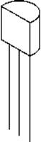
This basic circuit combines the BlinkM MinM smart LED with the TMP36 temperature sensor that comes in a package similar to our transistor from the last project, but with a different pin connection. It's still super-easy to hook up and, once connected to +5 volts and ground, the output pin will provide a linear reading that corresponds to the temperature measured in Celsius, as shown in Figure 7-2.
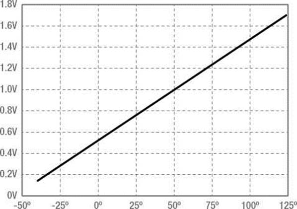
Figure 7-2. TMP36 output voltage versus temperature Celsius
The TMP36 has a 0.5v offset that we will have to compensate for, but because of the linearity of the output signal only a little math is needed to determine the ambient temperature to within ± 2° Celsius. There are many other temperature sensors like these that we could use or we could add additional sensors, like ones for measuring humidity or barometric pressure, but we are going to keep it simple for this project. You might also want a little more power out of your LEDs, so you could substitute one of the other varieties of the BlinkM, even connecting a MaxM to an entire string of LEDs. For more information and to download the data sheet and quick-start guide, check out ThingM's web site at http://thingm.com/products/blinkm/. Now, let's connect our project, as shown in Figures 7-3 and 7-4.
+5 VDC
1
PIN A0
>
2
3
TMP36
1 23
BLINKM
|
GND |
||
|
+5 VDC |
+5 VDC |
|
|
PIN A4 |
SDA |
|
|
PIN A5 |
SCL |
GND
GND
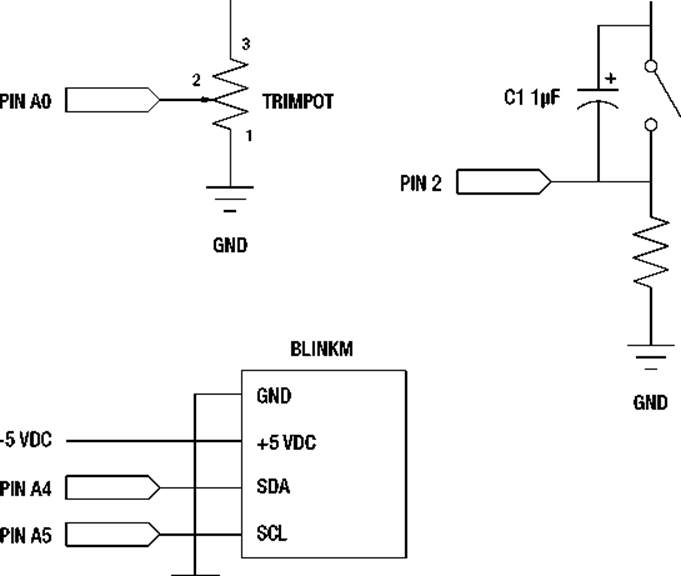
Figure 7-3. Ambient Temps schematic
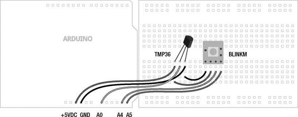
Figure 7-4. Ambient Temps illustration
Uploading the Source Code
This sketch for this project will serve as a good example of how to compartmentalize our code by writing and using custom functions, which a good part of this chapter is dedicated to. There are three main parts to this code: reading and calculating the current temperature; mapping that reading to a usable HSB color value; and then sending the appropriate commands to the BlinkM to get it to respond with the color that we want. Let's get this project wired up and the source code in Listing 7-3 uploaded, and continue our discussion from there.
Listing 7-3. Ambient Temps Source Code
#include <Wire.h>
const int blinkM = 0x09; const int temperaturePin = A0;
const boolean degreesF = true;
const int hot = 100; const int cold = 40; const int hotColor = 0; const int coldColor = 170; const int brightness = 255;
void setup() {
Wire.begin(); stopScript(blinkM); setFadeSpeed(blinkM, 1);
}
void loop() {
int hue = map(temperature(), hot, cold, hotColor, coldColor); hue = constrain(hue, hotColor, coldColor); fadeToHSB(blinkM, hue, 255, brightness); delay(10000);
}
float temperature() {
float voltage = (analogRead(temperaturePin) / 1024.0) * 5.0;
float celsius = (voltage - 0.5) * 100.0;
float fahrenheit = (celsius * 1.8) + 32.0;
if (degreesF == true) return fahrenheit;
else return celsius;
}
void stopScript(byte address) {
Wire.beginTransmission(address);
Wire.write('o');
Wire.endTransmission();
}
void setFadeSpeed(byte address, byte fadespeed) { Wire.beginTransmission(address);
Wire.write('f');
Wire.write(fadespeed);
Wire.endTransmission();
}
void fadeToHSB(byte address, byte hue, byte saturation, byte brightness) { Wire.beginTransmission(address);
Wire.write('h');
Wire.write(hue);
Wire.write(saturation);
Wire.write(brightness);
Wire.endTransmission();
}
Source Code Summary
The first line of our sketch is necessary for using the Wire library that will allow the Arduino and BlinkM to talk to each other using a protocol called I2C, discussed at length in Chapter 10. Since we don't need to worry about that for now, let's jump to the variable declarations and see what they do.
const int blinkM = 0x09; const int temperaturePin = A0;
These first two lines set up the locations for the BlinkM and our temperature sensor. The first is an address to identify which BlinkM to talk to. This value comes as the default and if we only use one BlinkM, will not need to be changed. The second line establishes that our temperature sensor is connected to pin A0.
const boolean degreesF = true;
const
const
const
const
const
int hot = 100; int cold = 40; int hotColor = 0; int coldColor = 170; int brightness = 255;
This block of code declares the variables that can be used to configure various settings in our sketch. The first of these turns on Fahrenheit temperatures using true and by using false will revert to Celsius temperatures. The variable hot and cold allows us to specify what we think is hot and cold for our location—hot in London is perhaps not the same as hot in Phoenix. With these values set, any temperature below the cold limit will remain blue while any temperature hotter than the hot value will stay red. Since it is entirely possible that hot being red and cold being blue might be too obvious for you, you can change the values for hotColor and coldColor to establish the two extreme colors in HSB values. Finally, the BlinkM can be insanely bright, so we have an option to specify a different brightness level that will dim the LED without changing its color.
Wire.begin(); stopScript(blinkM); setFadeSpeed(blinkM, 1);
Because we are using several new functions in our sketch, the code in our setup() function is a little sparse. The first line starts the communication protocol that we will use for the BlinkM. Again, this will be covered in greater detail later in this book. The stopScript() and setFadeSpeed() functions are two of our custom functions used for setting options in the BlinkM. We'll talk about these in a moment, so let's move on to the code in our loop() function.
int hue = map(temperature(), hot, cold, hotColor, coldColor);
We begin here with mapping whatever value is returned from the temperature () function, as defined by the hot and cold endpoints, to whatever hue value will correspond to that temperature, as defined by the hotColor and coldColor variables. Because it is possible for these values to end up outside of this range, we will also need the constrain() function:
hue = constrain(hue, hotColor, coldColor);
This line will keep the LED from suddenly turning pink if the values were to get a little wonky (technically speaking). Once we have our hue value established, we need to send this out to our BlinkM as we did in the following:
fadeToHSB(blinkM, hue, 255, brightness); delay(10000);
The function fadeToHSB() will send a command to the BlinkM, telling it to fade to whatever color is specified in the hue that we just worked out; a saturation of 255, although you could play with this number; and the brightness that we established at the beginning of our sketch. We then delay for 10 seconds just to keep the LED from flickering because of small fluctuations in temperature. Now let's look at our functions.
float temperature() {
float voltage = (analogRead(temperaturePin) / 1024.0) * 5.0;
float celsius = (voltage - 0.5) * 100.0;
float fahrenheit = (celsius * 1.8) + 32.0;
if (degreesF == true) return fahrenheit;
else return celsius;
}
The temperature() function is a different data type than what we normally see, so it can return a value that is of the float data type. The first line of this function reads the temperature sensor and converts the values from a range of 0–1024 to a voltage from 0 to 5 volts. To obtain the degrees in Celsius we need to offset 0.5v for the TMP36, as described in the device's data sheet, and then multiply this value by 100.0, as shown in Figure 7-2. Once we have the degrees Celsius, we can convert this value to Fahrenheit by multiplying 1.8 and adding 32. The function ends by checking whether or not we wanted degrees in Fahrenheit and returns the appropriate temperature value.
Our next three functions are used to send specific commands to the BlinkM to change its default settings and output the correct color. The specific commands can be found in the BlinkM data sheet available from ThingM's web site. Our first function, stopScript(), disables the default startup script by sending it the character “o” as follows:
void stopScript(byte address) {
Wire.beginTransmission(address);
Wire.write('o');
Wire.endTransmission();
}
Our next function is not entirely necessary, but it sets the BlinkM to its slowest fade speed. Each time we tell the BlinkM to change color, it will fade from its current color to the new one. This is a nice little feature and by slowing it down even more, we help make our device more ambient, slowly changing colors in the background. The setFadeSpeed() function will send the BlinkM the character “f” followed by the fade speed with a possible range of 1–255, with 1 being the slowest and 255 being instantaneous. The default speed is 15.
void setFadeSpeed(byte address, byte fadespeed) {
Wire.beginTransmission(address);
Wire.write('f');
Wire.write(fadespeed);
Wire.endTransmission();
}
The last function, fadeToHSB(), is what makes things so easy for us and is the reason for choosing the BlinkM over the standard RGB LED.
void fadeToHSB(byte address, byte hue, byte saturation, byte brightness) { Wire.beginTransmission(address);
Wire.write('h');
Wire.write(hue);
Wire.write(saturation);
Wire.write(brightness);
Wire.endTransmission();
}
Using this function, we send it four pieces of information: the BlinkM's address followed by the values for hue, saturation, and brightness. The function will send the character “h” to the BlinkM followed by the HSB values, and the BlinkM will work out the math for fading from one color to another.
Well, that was a fairly lengthy overview of how the code works, but we should back up now and look at what's involved in writing and working with functions like those in our project example.
Writing Functions
So far in this chapter, we have seen some additional functions that are part of the main Arduino library, as well as some that we have written. We've also looked at how these functions can extend the capabilities of our code. Functions provide the programmer with the ability to compartmentalize chunks of code that are related by a very specific purpose. We are not limited to only those functions that are provided in the Arduino programming environment, as in fact, writing functions is the bread and butter of writing source code for C and something that any seasoned Arduino programmer will do to make their code function better, take less memory space, make the code better organized, reduce the possibilities for errors, and generally make it easier to read.
The uses for functions are really endless and we have already been using them from the very beginning. Maybe we need to perform certain arithmetic conversions on a particular analog reading. We could write a specific function to perform these tasks for us and return the finished converted values back to the main loop() function. Maybe we want to turn on a set of digital outputs all at the same time or in a sequence any time a certain condition has been met. We could make a function that we could pass a condition or value to and have the function decide what to do with it. For example, let's say we wanted to create a function that will turn on and off the pin 13 LED. That could look something like the following:
void blinkLED() { digitalWrite(l3, HIGH); delay(l000); digitalWrite(13, LOW); delay(1000);
}
Now, every time we call the blinkLED() function in our sketch, the pin 13 LED will turn on and off once before returning to whatever the code was doing before. Now, let's looks at exactly what's involved in making these functions work.
Declaring Functions
To begin working with a new function, we need to first declare it. A function declaration involves establishing the function's return data type, the function's name, and any parameters that are being passed to the function bracketed by parenthesis. We will discuss returns and parameters in a moment, but for now you should be comfortable with what a function declaration looks like. In our last example, the function declaration is fairly simple, as follows:
void blinkLED() {
The keyword void is our function's return data type. The name given to our function in this case is blinkLED. This provides an understandable name for our function that tells us at a quick glance what we can expect the function to do. Since we are not talking about parameters at the moment, the parentheses are left empty. Finally, we have the first of two curly braces that enclose the code needed in the function.
Any new function that we add to our sketch must be done outside any other function that we might have, including the setup() and loop() functions that every sketch using the Arduino libraries will have. For the most part, it really doesn't mater where a function is declared within the sketch, although we often find ourselves usually declaring them after the loop() function, more out of habit than anything.
Calling Functions
With a function written, such as our blinkLED() function from earlier, we need to call the function when we want it to do its job. The thing is, whenever we have talked about a function in this book, we have been calling it in our code. So to call our function, we would write a simple statement like the following:
blinkLED();
And that is all there is to it. When the function is called, program flow jumps to that function, executes the block of code, and when the function has ended, program flow returns to the next line after our function call. So, building on our new function, if in our loop() function we only had the following:
void loop() { blinkLED();
}
This would effectively rewrite our blinking LED sketch by using a function. Each time through the loop, the blinkLED() function is called, and inside that function, the LED on pin 13 is turned on for 1 second and turned off for 1 second. When all of the statements inside the function have been executed, program flow returns to the loop() function and it all starts over again.
Function Returns
Our example function blinkLED() doesn't admittedly do all that much. To make things more interesting, we could ask our function to perform some sort of operation and give us a result back in a nice value that we could then do something with. This act of calling a function and passing a value from that function back to its calling function is known as a function return.
In declaring a function, the first thing we need to declare is the function's return data type. For the most part in this book, when a function has been declared, it has been done using the void data type. I know, void wasn't one of the options when we looked at variable data types. That's because it's not really that useful for variables, but when it comes to functions, it's a good idea to tell the compiler that the function being declared will have no value. In order for our function to have a value though, we need to declare a data type that matches the expected value to be returned. Take the following, for example:
int readSensor() {
Here we are declaring a new function called readSensor() of the int, or integer data type. Just as with integer type variables, this will give us an expected range of values from -32,768 to 32,767. We can pretty much use any of the data types discussed earlier for variables, including long, unsigned, or even boolean.
Now let's look at how the function can actually return a value. Let's say that we want our readSensor() function to not only read a sensor, but to also smooth out our sensor readings by taking 5 samples very quickly, averaging those samples, and returning that value in a format that we can use for PWM. The following is the function:
int readSensor() { int sensorValue = 0; for (int i=0; i<5; i++) {
sensorValue = sensorValue + analogRead(A0); delay(10);
}
sensorValue = map(sensorValue, 0, 5115, 0, 255); return sensorValue;
}
In this function, we first create a new local variable called sensorValue. Then we start a for loop that will loop five times. Each time through the loop, it will add the current sensor reading to the running total and pause for 10 milliseconds just to get a better average. Once we have our new total, we will use the map() function to map our reading to a value with a new range of 0–255. That odd number 5115 is equal to 5 * 1023, or the total value that we could possibly get by reading an analog pin five times and adding all those values together. We could have divided sensorValue by 5 and then divided the result by 4, but the map() function gives us some options to adjust these reading later on. We end the readSensor() function with the return statement, as follows:
return sensorValue;
This line returns the value of sensorValue back to the calling function. Let's say we had the following statement in our loop() function:
int sensorValue = readSensor();
This line calls the readSensor() function and returns the final conditioned sensor reading back to the loop() function, assigning that value to the variable sensorValue. In this case, we have used the variable sensorValue twice but that's okay because if you remember, a function's scope is dependant on where it was declared. In each case here, we have declared them locally and so their scope does not extend beyond the function that they were declared in.
In addition to that, a value that is returned by a function is immediately forgotten by that function. We will need to do something with that returned value in our main loop() function or it will be lost to us.
Now we have made the assumption here that we want to use a function return to specifically return a value. We could also use the return keyword to immediately exit a function if a certain condition was met. The following is a hypothetical example:
if (sensorValue < 100) return;
Maybe we want to ignore readings that are below a certain threshold, so we could use the return keyword to exit a function without returning a value. Here we do that using an if statement with a condition that if true, will result in leaving the function and returning to normal program flow.
Function Parameters
In our last example we assumed that the analog pin being used was A0, but that might be a little shortsighted. Instead we can use function parameters to pass data like a pin number to the function, in this case to tell the function which pin to read from. Let's look at that function again, as follows:
int readSensor(int sensorPin) { int sensorValue = 0; for (int i=0; i<5; i++) {
sensorValue = sensorValue + analogRead(sensorPin); delay(10);
}
sensorValue = map(sensorValue, 0, 5115, 0, 255); return sensorValue;
}
Function parameters are kind of like variables, but they are declared inside the parenthesis in the function declaration. Let's look at the following revised function declaration:
int readSensor(int sensorPin) {
Here we have added the function parameter of sensorPin and assigned it the integer data type. That tells the function what kind of value to expect being passed to it. Elsewhere in the function we can use the function parameter just like we would another variable. We did that in the following line:
sensorValue = sensorValue + analogRead(sensorPin);
Here, sensorPin will correspond to the function parameter being passed to the function. As long as we make sure that the specified data type matches the value being sent to the function, all should be fine. The following is what the function call would look like in the loop() function:
int sensorValue = readSensor(A0);
All we have done is given the function call the expected data inside the parenthesis, in this case the pin number we want to get our value from. With this modified function, it will now work for all six analog input pins just by specifying which pin we want to read from as a function parameter.
Now, this example only has one function parameter, but it is also possible to have multiple function parameters as long as commas separate them as we did in our project code with the fadeToHSB() function. It is also possible to specify parameters with any valid data type, not just integers. Remember though, just like a function return value, the parameters passed to a function are only temporary—they will not be remembered by that function once the function ends.
Building on this idea of writing functions, we can use a type of function that is triggered by a condition in hardware called an interrupt. This would be pretty handy for interrupting the code for a short time to perform a specific action. Let's look at a second project, HSB Color Mixer, using the BlinkM again to see how interrupts work.
Project 7: HSB Color Mixer
In this project, we've kept the BlinkM MinM, but we replaced the TMP36 temperature sensor with a pushbutton like we used in Chapter 5 in addition to a trimpot, also known as a potentiometer, although some other variable resistor could work as well. This project will allow us to cycle through hue, saturation, and brightness on the BlinkM to set a specified color. Better yet, it gives us a good excuse for using a special kind of function that uses hardware interrupts, which we will explain in this chapter.
Hooking It Up
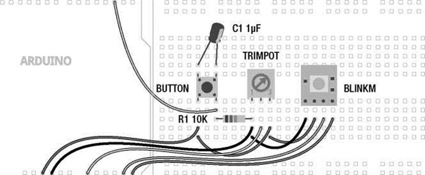
The circuit shown in Figures 7-5 and 7-6 adds a pushbutton and trimpot, or other analog sensor, to our BlinkM to make an HSB Color Mixer. We have increased the complexity of our circuit a bit, but each of the components is fairly basic, using principles that you've seen before. We did have to make a slight modification to our pushbutton circuit by adding a small electrolytic capacitor across the positive and negative sides of the pushbutton. Electrolytic capacitors are polarized, so it is important that the white stripe attaches to the ground side of the switch. It's maybe not the best solution for hardware debouncing, but it will work for now, although other options can be found through a quick search online. While we had gotten away without using this before, the hardware interrupt happens so quickly that we need to debounce our switch using additional hardware to slow the switch down a little. This will prevent false readings without using a delay—which is necessary, as you will see in a moment.
+5 VDC +5 VDC
SW1
R4 10K
GND
Figure 7-5. HSB Color Mixer schematic
PIN 2
+5VDC GND A0 A4 A5
Figure 7-6. HSB Color Mixer illustration
Uploading the Source Code
Our sketch for this project will build from the first project code in this chapter, bringing back a few of the functions that we need to control the BlinkM. The source code in Listing 7-4 uses a hardware interrupt and a switch... case statement, so that we will be able to switch through the hue, saturation, and brightness for the BlinkM using the button and the trimpot to set each value. Let's upload the code and see how it works.
Listing 7-4. HSB Color Mixer Source Code
#include <Wire.h>
const int blinkM = 0x09; const int buttonInterrupt = 0; const int analogIn = A0;
int hue=0, saturation=0, brightness=0;
volatile int i = 0;
void setup() {
Wire.begin(); stopScript(blinkM); setFadeSpeed(blinkM, 15);
attachInterrupt(buttonInterrupt, selectHSB, RISING);
}
void loop() { switch (i) { case 0:
hue = map(analogRead(analogIn), 0, 1024, 0, 255); fadeToHSB(blinkM, hue, 255, 255); break; case 1:
saturation = map(analogRead(analogIn), 0, 1024, 0, 255); fadeToHSB(blinkM, hue, saturation, 255); break; case 2:
brightness = map(analogRead(analogIn), 0, 1024, 0, 255); fadeToHSB(blinkM, hue, saturation, brightness);
}
delay(50);
}
void selectHSB() {
++i %= 4;
}
void stopScript(byte address) {
Wire.beginTransmission(address);
Wire.write('o');
Wire.endTransmission();
}
void setFadeSpeed(byte address, byte fadespeed) { Wire.beginTransmission(address);
Wire.write('f');
Wire.write(fadespeed);
Wire.endTransmission();
}
void fadeToHSB(byte address, byte hue, byte saturation, byte brightness) { Wire.beginTransmission(address);
Wire.write('h');
Wire.write(hue);
Wire.write(saturation);
Wire.write(brightness);
Wire.endTransmission();
}
Source Code Summary
Since a lot of this code looks the same as from earlier, we'll keep this summary limited to the new things, beginning with the following variable declarations:
const int buttonInterrupt = 0;
const int analogIn = A0;
int hue=0, saturation=0, brightness=0;
The first line sets up our interrupt pin, although as will be explained in a moment, this number is not the same as the Arduino pin number that our button is connected to. We then set up our analog input, followed by some variables to set the values for hue, saturation, and brightness. Our next variable, which follows, is a little different:
volatile int i = 0;
As we discussed earlier, a variable's value is not kept inside of a function that uses it, so we would loose track of which button state we were on unless we told the compiler to save this information for us. We've done that here with the volatile variable qualifier attached to our index variable, so that we can keep track of the value—hue, saturation, or brightness—we are currently adjusting.
Our setup function is the same as in our last project, except for the addition of the following line:
attachInterrupt(buttonInterrupt, selectHSB, RISING);
Here is the function that establishes which interrupt we will be using, the function to call when the interrupt is triggered, and what condition will trigger the interrupt. This will be explained shortly.
Our loop function predominately features a switch... case statement that will adjust the hue, saturation, or brightness depending on the number of button presses. So, beginning with the switch statement and the first case, as follows:
switch (i) { case 0:
hue = map(analogRead(analogIn), 0, 1024, 0, 255);
fadeToHSB(blinkM, hue, 255, 255);
break;
The switch statement has been tied to the value of the variable i, which will be incremented later in the code. If i is equal to 0, then case 0 will execute. This case will read the value of the analog input pin and map that value from a range of 0–1024 to 0–255. This value is then sent to the BlinkM using the fadeToHSB() function that will also set the saturation and brightness to their highest setting while we adjust the hue. Finally, we've used the break statement to exit the switch statement without running the other cases.
Cases 1 and 2 will respectively adjust the saturation and brightness, but only when the buttons index had been incremented. Otherwise, for as long as i is equal to a value between 0 and 2, then that corresponding case will run. To increment i, we use an interrupt service routine, which is a special kind of function, as follows:
void selectHSB() {
++i %= 4;
}
This is the extent of our interrupt service routine. It's one and only job is to increment the index variable i by one each time the button is pressed and to keep the numbers to within four possible outcomes, 0, 1, 2, and 3. This line is a little tricky... By placing the ++ in front of the variable i, we first increment i by one before taking the modulo of i and then reassigning the new value back to i. This is a little different from the normal i++ but it's a fairly convenient way to condense a couple lines of code into one.
The rest of the functions are the same BlinkM functions that we used before, so let's skip over these to have a little closer look at how advanced functions work with hardware interrupts.
Hardware Interrupts
With an idea as to what functions can do for us, we can move on to a different kind of function—one that is driven by specific hardware in the microcontroller. The reasons for using interrupts are many; maybe we have a lot of code in our loop () function and sitting there waiting for a button press would slow things down too much or maybe we might even miss the button press all together. Or instead we might be using a photo sensor or interrupter that triggers when something gets close and it is important to stop a motor right at that exact time. These things are possible with a hardware interrupt that can be configured on one of two digital pins to trigger a unique kind of advanced function called an interrupt service routine (ISR). When the interrupt is triggered, the ISR will be called regardless of whatever the program is in the middle of. Like using one of the internal timers, monitoring of the hardware interrupt pin happens in the background and the jump to the ISR can happen within four instructions, so fairly quickly. After the ISR has been executed, program flow returns back to where it left off before the interrupt and, if done correctly, with little effect on the rest of the code.
An ISR looks a lot like a regular function but there are a few rules that we need to stick to. First, as was shown in our second project code, the ISR should be kept as short as possible, often only three to four lines of code at the maximum, so as to not overly disrupt the program flow and prevent the interrupt from being triggered again while executing the ISR. If we have a longer ISR than that, we need to disable the interrupt briefly while the ISR is running. Likewise, timing related functions would not work properly within the ISR because they use the same hardware timer. For example, millis () will not increment and delay() will not work at all. Other than that, an ISR is declared just like a normal function, but in order to use a hardware interrupt we need to first attach it in our code.
attachInterrupt()
The attachInterrupt() function enables hardware interrupts and links a hardware pin to an ISR to be called when the interrupt is triggered. This function also specifies the type of state change that will trigger the interrupt. Its syntax follows:
attachInterrupt(interrupt, function, mode)
The first parameter is the number of the interrupt. On the Arduino Uno there are only two possible hardware interrupts, 0 and 1, which correspond to digital pins 2 and 3 respectively. Note that this parameter refers to the interrupt number and not the pin number. The second parameter is the name of the function that will serve as the interrupt service routine that we will want to execute when the interrupt is triggered. Finally, we have the mode that represents the specific state change that will cause the interrupt to trigger. There are four possible modes, as shown in Figure 7-7, which include LOW,
CHANGE, RISING, and FALLING.
0V----------
t
RISING
5V
5V
ttttttttt ttttt
LOW
5V
0V--------- ---------
է է t
CHANGE
5V ---------
0V--------- ---------
է t
FALLING
Figure 7-7. State changes
LOW triggers when the interrupt pin is in the LOW state. This mode will continuously trigger the interrupt for as long as it remains in this condition and because of this is not used as much as the other modes. CHANGE will trigger when the state of an interrupt pin changes either from HIGH to LOW or from LOW to HIGH. RISING will only trigger the interrupt when the signal goes from LOW to HIGH while FALLING will trigger on the reverse going from HIGH to LOW. Because of how our example circuit is connected, the button will send a signal of HIGH when triggered so we used the RISING mode to trigger the interrupt when the digital pin's state changes from LOW to HIGH.
Once the interrupt has been properly configured, often but not always in the setup() function, we need to write the ISR function. The function selectHSB() is a fairly good example of a short and succinct ISR. Its entire job is to increment the counter i and keep those values to a possible range of 0–3. Remember though, that in order for us to use the indexing variable i elsewhere in our sketch, we need to first use the volatile variable qualifier at the beginning of our sketch. Because the interrupt could sneak in there and change the value of a variable without the rest of the sketch knowing it, by using the volatile keyword we can tell the compiler to put the variable data in a more secure place in memory to prevent weird things from happening to our number.
detachInterruptO
With our hardware interrupt enabled, it is possible that in a given application, we might need to change the mode of an interrupt, for example to change it from RISING to FALLING. To do this we would need to first stop the interrupt by using the detachInterrupt() function. Its syntax is fairly straightforward, as follows:
detachInterrupt(interrupt)
With only one parameter to determine which interrupt we are disabling, this parameter is specified as either 0 or 1. Once the interrupt has been disabled, we can then reconfigure it using a different mode in the attachInterrupt() function.
Summary
With that, we wrap up our discussion of advanced junctions. Now we know how to create a hardware interrupt and the corresponding interrupt service routine that will cause the Arduino to drop everything and perform the code in the specified function when the interrupt is triggered. We looked at how to write our own functions, which included talking about how functions work along with function parameters and function returns. And, we even checked out a few functions for timing and randomness that we had not been able to discuss properly before now.
From here, we are going to explore a unique type of variable called an array and because inevitably arrays will begin to consume large chunks of the Arduino microcontroller's memory, we will also discuss the different kinds of memory available and how to put these storage spaces to use. This will also bring us into some areas of code not given the full Arduino treatment, so it might be a good idea to take a little breather before we keep going, but I'm sure you'll handle things just fine.