Programming Arduino Getting Started with Sketches (2012)
6
Input and Output
The Arduino is about physical computing, and that means attaching electronics to the Arduino board. So you need to understand how to use the various options for your connection pins.
Outputs can be digital, which just means switched between being at 0V or at 5V, or analog, which allows you to set the voltage to any voltage between 0V and 5V—although it’s not quite as simple as that, as we shall see.
Likewise, inputs can either be digital (for example, determining whether a button pressed or not) or analog (such as from a light sensor).
In a book that is essentially about software rather than hardware, we are going to try and avoid being dragged into too much discussion of electronics. However, it will help you to understand what is happening in this chapter if you can find yourself a multimeter and a short length of solid core wire.
Digital Outputs
In earlier chapters, you have made use of the LED attached to digital pin 13 of the Arduino board. For example, in Chapter 5, you used it as a Morse code signaler. The Arduino board has a whole load of digital pins available.
Let’s experiment with one of the other pins on the Arduino. You will use digital pin 4, and to see what is going on, you will fix some wire to your multimeter leads and attach them to your Arduino. Figure 6-1 shows the arrangement. If your multimeter has crocodile clips, strip the insulation off the ends of some short lengths of solid core wire and attach the clip to one end, fitting the other end into the Arduino socket. If your multimeter does not have crocodile clips then wrap one of the stripped wire ends around the probe.
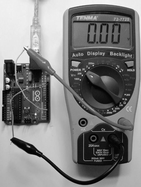
Figure 6-1 Measuring outputs with a multimeter
The multimeter needs to be set to its 0-20V direct current (DC) range. The negative lead (black) should be connected to the ground (GND) pin and the positive to D4. The wire is just connected to the probe lead and poked into the socket headers on the Arduino board.
Load sketch 6-01:
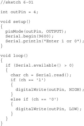
At the top of the sketch, you can see the command pinMode. You should use this command for every pin that you are using in a project so that Arduino can configure the electronics connected to that pin to be either an input or an output, as in the following example:
![]()
As you might have guessed, pinMode is a built-in function. Its first argument is the pin number in question (an int), and the second argument is the mode, which must be either INPUT or OUTPUT. Note that the mode name must be all uppercase.
This loop waits for a command of either 1 or 0 to come from the Serial Monitor on your computer. It it’s a 1, then pin 4 will be turned on; otherwise, it will be turned off.
Upload the sketch to your Arduino and then open the Serial Monitor (shown in Figure 6-2).
So, with the multimeter turned on and plugged into the Arduino, you should be able to see its reading change between 0V and about 5V as you send commands to the board from the Serial Monitor by either pressing 1 and then Return or pressing 0 and then Return. Figure 6-3 shows the multimeter reading after a 1 has been sent from the Serial Monitor.
If there are not enough pins labeled “D” for your project, you can actually use the pins labeled “A” (for analog) as digital outputs too. To do this, you just have to add 14 to the analog pin number. You could try this out by modifying the first line in sketch 6-01 to use pin 14 and moving your positive multimeter lead to pin A0 on the Arduino.
That is really all there is to digital outputs, so let’s move on swiftly to digital inputs.
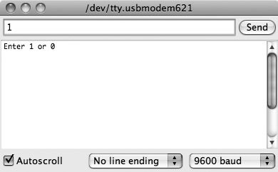
Figure 6-2 The Serial Monitor
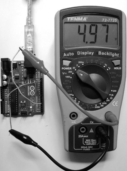
Figure 6-3 Setting the output to High
Digital Inputs
The most common use of digital inputs is to detect when a switch has been closed. A digital input can either be on or off. If the voltage at the input is less than 2.5V (halfway to 5V), it will be 0 (off), and if it is above 2.5V, it will be 1 (on).
Disconnect your multimeter and upload the sketch 6-02 onto your Arduino board:
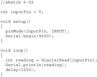
As with using an output, you need to tell the Arduino in the setup function that you are going to use a pin as an input. You get the value of a digital input using the digitalRead function. This returns 0 or 1.
Pull-up Resistors
The sketch reads the input pin and writes its value to the Serial Monitor once per second. So upload the sketch and open the Serial Monitor. You should see a value appear once per second. Push one end of your bit of wire into the socket for D5 and pinch the end of the wire between your finger, as shown in Figure 6-4.
Continue pinching for a few seconds and watch the text appear on the Serial Monitor. You should see a mixture of ones and zeros appear in the Serial Monitor. The reason for this is that the inputs to the Arduino board are very sensitive. You are acting as an antenna, picking up electrical interference.
Take the end of the wire that you were holding and push it into the socket for +5V as shown in Figure 6-5. The stream of text in the Serial Monitor should change to ones.
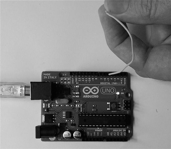
Figure 6-4 A digital input with a human antenna
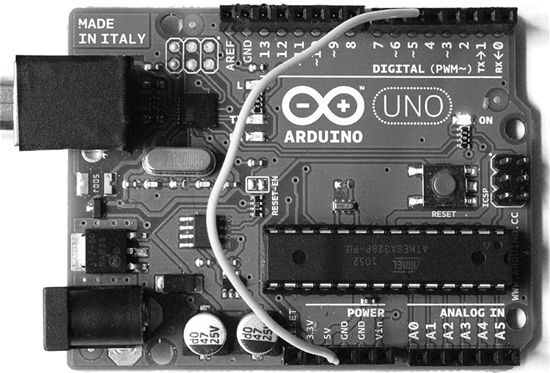
Figure 6-5 Pin 5 connected to +5V
Now take the end that was in +5V and put it into one of the GND connections on the Arduino. As you would expect, the Serial Monitor should now display zeros.
A typical use for an input pin is to connect a switch to it. Figure 6-6 shows how you might be expecting to connect your switch.
The problem with this is that if the switch is not closed, then the input pin is not connected to anything. It is said to be floating, and could easily give you a false reading. You need your input to be more predictable, and the way to do this is with what is called a pull-up resistor. Figure 6-7 shows the standard use of a pull-up resistor. It has the effect that if the switch is open, then the resistor pulls up the floating input to 5V. When you press the switch and close the contact, the switch overrides the effect of the resistor, forcing the input to 0V. One side-effect of this is, while the switch is closed, 5V will be across the resistor, causing a current to flow. So, the value of the resistor is selected to be low enough to make it immune from any electrical interference, but at the same time high enough to prevent excessive current drain when the switch is closed.
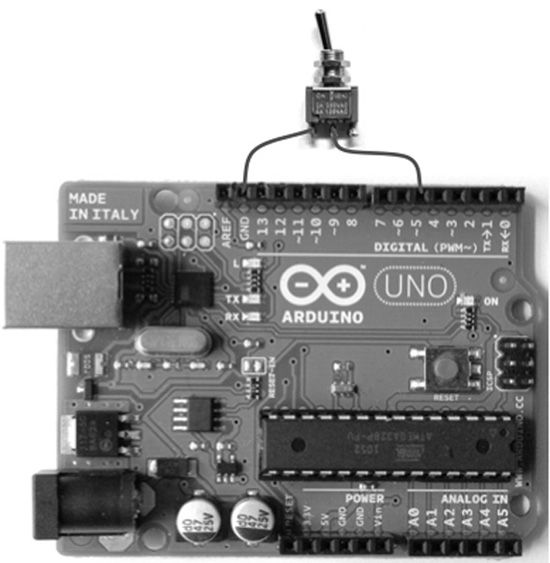
Figure 6-6 Connecting a switch to an Arduino board
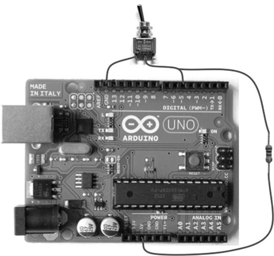
Figure 6-7 Switch with a pull-up resistor
Internal Pull-up Resistors
Fortunately, the Arduino board has software-configurable pull-up resistors built into the digital pins. By default, they are turned off. So all you need to do to enable the pull-up resistor on pin 5 for sketch 6-02 is to add the following line:
![]()
This line goes in the setup function right after you define the pin as an input. It may seem a little strange to do a digitalWrite to an input, but this is just the way it works.
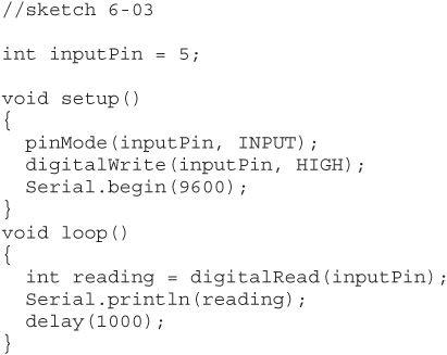
Sketch 6-03 is the modified version. Upload it to your Arduino board and test it by acting like an antenna again. You should find that this time the input stays at 1 in the Serial Monitor.
Debouncing
When you press a pushbutton, you would expect that you would just get a single change from 1 (with a pull-up resistor) to 0 as the button is depressed. Figure 6-8 shows what can happen when you press a button. The metal contacts in the button bounce. So a single button press becomes a series of presses that eventually stabilize.
All this happens very quickly; the total time span of the button press on the oscilloscope trace is only 200 milliseconds. This is a very “ropey” old switch. A new tactile, click-type button may not even bounce at all.
Sometimes bouncing does not matter at all. For instance, sketch 6-04 will light the LED while the button is pressed. In reality, you would not use an Arduino to do this; we are firmly in the realms of theory rather than practice here.
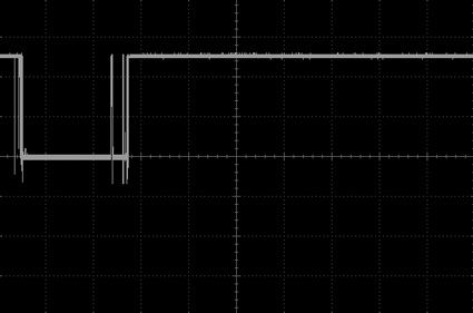
Figure 6-8 Oscilloscope trace of a button press
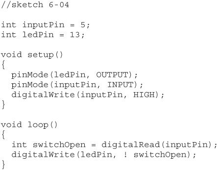
Looking at the loop function of sketch 6-04, the function reads the digital input and assigns its value to a variable switchOpen. This is a 0 if the button is pressed and a 1 if it isn’t (remember that the pin is pulled up to 1 when the button is not pressed).
When you program digitalWrite to turn the LED on or off, you need to reverse this value. You do this using the ! or not operator.
If you upload this sketch and connect your wire between D5 and GND (see Figure 6-9), you should see the LED light. Bouncing may be going on here, but it is probably too fast for you to see and does not matter.
One situation where key bouncing would matter is if you were making your switch toggle the LED on and off. That is, if you press the button, the LED comes on and stays on, and when you press the button again, it turns off. If you had a button that bounced, then whether the LED was on or off would just depend on whether you had an odd or even number of bounces.
Sketch 6-05 just toggles the LED without any attempt at “debouncing.” Try it out using your wire as a switch between pin D5 and GND:
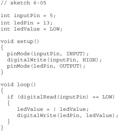
You will probably find that sometimes the LED toggles, but other times it appears not to toggle. This is bouncing in action!
A simple way to tackle this problem is simply to add a delay after you detect the first button press, as shown in sketch 6-06:
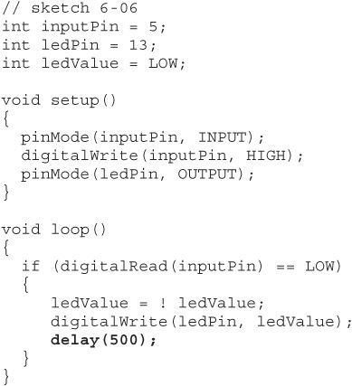
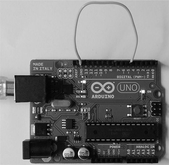
Figure 6-9 Using a wire as a switch
By putting a delay here, nothing else can happen for 500 milliseconds, by which time any bouncing will have subsided. You should find that this makes the toggling much more reliable. An interesting side-effect is that if you hold the button down, the LED just keeps flashing.
If that is all there is to the sketch, then this delay is not a problem. However, if you do more in the loop, then using a delay can be a problem; for example, the program would be unable to detect the press of any other button during that 500 milliseconds.
So, this approach is sometimes not good enough and you will need to be a bit more sophisticated. You can write your own advanced debouncing code by hand, but doing so gets complicated and fortunately some fine folks have done all the work for you.
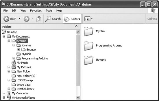
Figure 6-10 Adding the Bounce library in Windows
After downloading the file, unzip it and place the unzipped folder, called Bounce, into the libraries subfolder in the folder where all your sketches are saved. On Windows, this folder is My Documents\Arduino, and on Mac and Linux, it is Documents/Arduino. If there is no libraries subfolder, then you will need to create one. Figure 6-10 shows the folder structure in Windows after a library has been added.
After adding the library, you need to restart the Arduino application for the changes to take effect. Once you do so, you can use the Bounce library in any sketches that you write.
Sketch 6-07 shows how you can use the Bounce library. Upload it to your board and see how reliable the LED toggling has become.
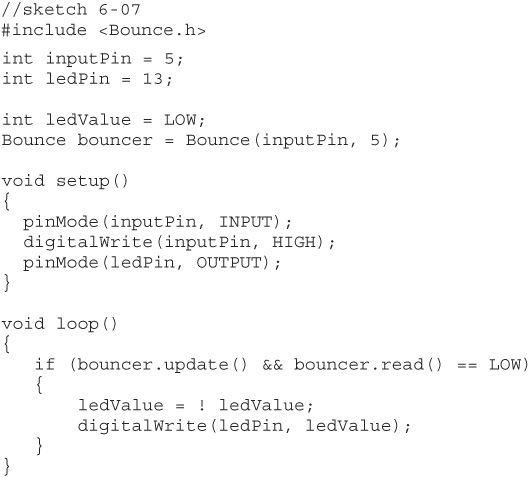
Using the library is pretty straightforward. The first thing that you will notice is this line:
![]()
This is necessary to tell the compiler to use the Bounce library.
You then have the following line:
![]()
Do not worry about the syntax of this line at the moment; it is actually C++ rather than C syntax, and you will not be meeting C++ until Chapter 11. For now, you will just have to be content to know that this sets up a bouncer object for the pin specified, with a debounce period of 5 milliseconds.
From now on, you use that bouncer object to find out what the key is doing rather than reading the digital input directly. It has put a kind of debouncing wrapper around your input pin. So, deciding whether a button has been pressed is wrapped up in this line:
![]()
The function update returns true if something has changed with the bouncer object and the second part of the condition checks whether the button went LOW.
Analog Outputs
A few of the digital pins—namely digital pins 3, 5, 6, 9, 10, and 11—can provide variable output other than just 5V or nothing. These are the pins on the board with a ~ or “PWM” next to them. PWM stands for Pulse Width Modulation, which refers to the means of controlling the amount of power at the output. It does so by rapidly turning the output on and off.
The pulses are always delivered at the same rate (roughly 500 per second), but the length of the pulses is varied. If you were to use PWM to control the brightness of an LED, then if the pulse were long, your LED would be on all the time. If, however, the pulses are short, then the LED is actually lit only for a small portion of the time. This happens too fast for the observer even to tell that the LED is flickering, and it just appears that the LED is lighter or dimmer.
Before you try using an LED, you can test this out with your multimeter. Set the multimeter up to measure the voltage between GND and pin D3 (see Figure 6-11).
Now upload sketch 6-08 to your board and open the Serial Monitor (see Figure 6-12). Enter the single digit 3 and press Return. You should see your volt meter register about 3V. You can then try any other number between 0 and 5.
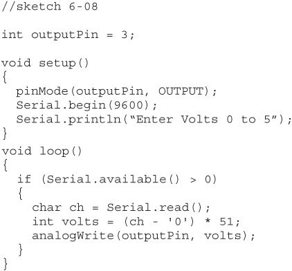
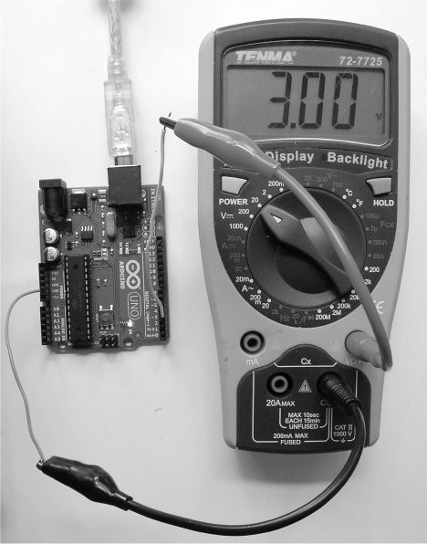
Figure 6-11 Measuring the analog output
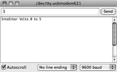
Figure 6-12 Setting the voltage at an analog output
The program determines the value of PWM output between 0 and 255 by multiplying the desired voltage (0 to 5) by 51. (Readers may wish to refer to Wikipedia for a fuller description of PWM.)
You can set the value of the output by using the function analogWrite, which requires an output value between 0 and 255, where 0 is off and 255 is full power. This is actually a great way to control the brightness of an LED. If you were to try to control the brightness by varying the voltage across the LED, you would find that nothing would happen until you got to about 2V; then the LED would very quickly get quite bright. By controlling the brightness using PWM and varying the average amount of time that the LED is on, you achieve much more linear control of the brightness.
Analog Input
Digital inputs just give you an on/off answer as to what is happening at a particular pin on the Arduino board. Analog inputs, however, give you a value between 0 and 1023 depending on the voltage at the analog input pin.
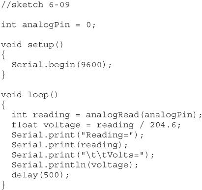
The program reads the analog input using the analogRead function. Sketch 6-09 displays the reading and actual voltage at the analog pin A0 in the Serial Monitor every half second, so open the Serial Monitor and watch the readings appear.
When you run this sketch, you will notice that the readings change quite a bit. As with the digital inputs, this is because the input is floating.
Take one end of the wire and put it into a GND socket so that A0 is connected to GND. Your readings should now stay at 0. Move the end of the lead that was in GND and put it into 5V and you should get a reading of around 1023, which is the maximum reading. So, if you were to connect A0 to the 3.3V socket on the Arduino board, the Arduino volt meter should tell you that you have about 3.3V.
Conclusion
This concludes our chapter on the basics of getting signals into and out of the Arduino. In the next chapter, we will look at some of the features provided in the standard Arduino library.
All materials on the site are licensed Creative Commons Attribution-Sharealike 3.0 Unported CC BY-SA 3.0 & GNU Free Documentation License (GFDL)
If you are the copyright holder of any material contained on our site and intend to remove it, please contact our site administrator for approval.
© 2016-2026 All site design rights belong to S.Y.A.