How to Use Objects: Code and Concepts (2016)
Part III: Events
Chapter 9. Structuring Applications with Graphical Interfaces
Chapter 7 introduced the technical and conceptual basis for building user interfaces using the SWT framework that comes with Eclipse. At the core, development comprises two aspects: setting up a widget tree with layout information to create the visual appearance, and attaching event-listeners to the individual widgets to implement the application’s reaction to user input. Although this seems simple enough, this basis alone is too weak for building larger applications: Since the application’s functionality tends to be scattered throughout event-listeners, one will almost certainly end up with a code base that cannot be maintained, extended, and ported to different platforms—in other words, software that must be thrown away and redeveloped from scratch.
This chapter investigates the architectural building block that keeps applications with user interfaces maintainable and portable: In the code, one always separates the application’s business logic strictly from its graphical interface. Section 9.1 introduces this approach, called model-view separation, and traces it through different examples within the Eclipse platform. Next, Section 9.2 discusses its conceptual and technical basis, the classical MODEL-VIEW-CONTROLLER pattern. Section 9.3 introduces the JFace framework, which complements the basic SWT widgets by connecting them to the application’s data structures. Section 9.4 uses a running example MiniXcel, a minimal spreadsheet implementation, to give a self-contained overview and to explore several implementation details of model-view separation that must be mastered to create truly professional applications. Finally, Section 9.5 adds the aspect of making edits undoable, which is indispensable for achieving usability.
Throughout the presentation, we will pay particular attention to the fact that model-view separation is deceptively simple: While the concept itself is rather straightforward, its rendering in concrete code involves many pitfalls. We will discuss particularly those aspects that have often been treated incorrectly in the work of novices to the field.
Before we start to delve into these depths of software design and implementation, there is one general piece of advice to set them into perspective:
Always gear the application toward the end users’ requirements.
The reason for placing this point so prominently is that it is neglected so![]() 258 often. As developers, we often get swept away by our enthusiasm for the technically possible and the elegance of our own solutions. However, software development is not a modern form of l’art pour l’art, but a means of solving other people’s pressing problems. These people, called “users,” do
258 often. As developers, we often get swept away by our enthusiasm for the technically possible and the elegance of our own solutions. However, software development is not a modern form of l’art pour l’art, but a means of solving other people’s pressing problems. These people, called “users,” do![]() 229 not care about the software’s internals; they care about their own workflows. So before you even start to think about the software’s view and model and
229 not care about the software’s internals; they care about their own workflows. So before you even start to think about the software’s view and model and![]() 28 the elegance of their separation, talk to the end users: What are their expectations of the software’s concrete behavior? How do they wish to interact with the software? Which particular tasks must the software support? The conscientious professional software engineer starts application development by learning about the users’ work—in other words, by learning about the software’s application domain. Everything said subquently must be subject to this overall guideline.
28 the elegance of their separation, talk to the end users: What are their expectations of the software’s concrete behavior? How do they wish to interact with the software? Which particular tasks must the software support? The conscientious professional software engineer starts application development by learning about the users’ work—in other words, by learning about the software’s application domain. Everything said subquently must be subject to this overall guideline.
9.1 The Core: Model-View Separation
Every application has a purpose for which it is built and which provides its unique value to its users. Correspondingly, the application contains code that implements the business logic to fulfill that purpose. Apart from that, most applications need a graphical user interface, simply because they have nontechnical users who do not appreciate command-line tools too much.
Apart from all of the strategic considerations related to software quality![]() 9.2.2 and maintenance, to be discussed later, it is useful to keep the code implementing the business logic and the user interface separate simply because they have different characteristics (Fig. 9.1). Users buy, for instance, CAD software because its business logic can do CAD and nifty computations, but they accept it into their working routine because they like the way they can interact with it. The business logic of a CAD system must be extremely reliable to prevent bridges from collapsing, and it must be stable enough through different software releases, for instance, to read the same files correctly throughout projects running for several years. The interface, in contrast, must be visually appealing and must adapt to the changing working habits of its users so that they can, for instance, exploit new input methods such as 3D interaction devices. To achieve stability, the business logic must adhere to rigorous contracts and must be tested comprehensively,
9.2.2 and maintenance, to be discussed later, it is useful to keep the code implementing the business logic and the user interface separate simply because they have different characteristics (Fig. 9.1). Users buy, for instance, CAD software because its business logic can do CAD and nifty computations, but they accept it into their working routine because they like the way they can interact with it. The business logic of a CAD system must be extremely reliable to prevent bridges from collapsing, and it must be stable enough through different software releases, for instance, to read the same files correctly throughout projects running for several years. The interface, in contrast, must be visually appealing and must adapt to the changing working habits of its users so that they can, for instance, exploit new input methods such as 3D interaction devices. To achieve stability, the business logic must adhere to rigorous contracts and must be tested comprehensively,![]() 7.11
7.11 ![]() 5.3.5 while the interface is event-based and cannot be tested easily, especially if it is liable to frequent changes. Finally, the business logic must deal with internal data structures and basic services such as file I/O, which are easily ported to different platforms. The API of graphical interfaces, in contrast, varies dramatically between platforms, and user interface code is usually not portable at all—for instance, from SWT to Swing. Keeping business logic and user interface separate is therefore first of all a matter of separation of concerns.
5.3.5 while the interface is event-based and cannot be tested easily, especially if it is liable to frequent changes. Finally, the business logic must deal with internal data structures and basic services such as file I/O, which are easily ported to different platforms. The API of graphical interfaces, in contrast, varies dramatically between platforms, and user interface code is usually not portable at all—for instance, from SWT to Swing. Keeping business logic and user interface separate is therefore first of all a matter of separation of concerns.
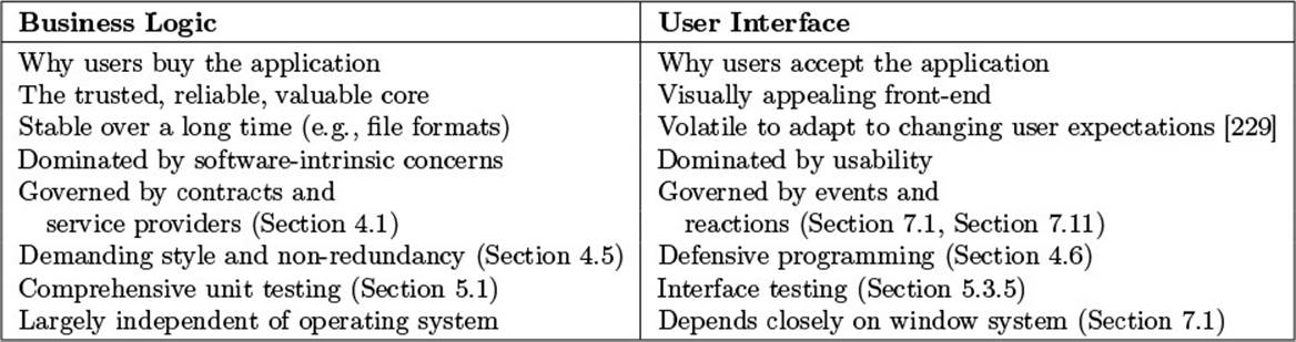
Figure 9.1 Characteristics of Business Logic and the User Interface
Keep the user interface and the business logic in different modules.
Accepting the goal of this separation, we have to investigate how it can be accomplished in the concrete software. Fig. 9.2 gives an overview, whose aspects we will explore in the remainder of this section. As a first step, one places the user interface and the business logic into separate modules, as indicated by the dashed horizontal dividing line in the figure. Referring![]() 9.2 to their roles in the MODEL-VIEW-CONTROLLER pattern, the business logic and the user interface are also called the model and the view, respectively, which explains the term model-view separation as a summary of the principle.
9.2 to their roles in the MODEL-VIEW-CONTROLLER pattern, the business logic and the user interface are also called the model and the view, respectively, which explains the term model-view separation as a summary of the principle.
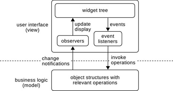
Figure 9.2 Overview of Model-View Separation
![]() A.1 In Eclipse, modules are implemented as plugins. Throughout the Eclipse code base, plugins with suffix .ui access the functionality provided by the corresponding plugins without that suffix. For instance, org.eclipse.jdt.ui accesses the Java Development Tools, whose logic comes in plugin org.eclipse.jdt.core, as well as org.eclipse.jdt.launching, org.eclipse.debug.core, and others.
A.1 In Eclipse, modules are implemented as plugins. Throughout the Eclipse code base, plugins with suffix .ui access the functionality provided by the corresponding plugins without that suffix. For instance, org.eclipse.jdt.ui accesses the Java Development Tools, whose logic comes in plugin org.eclipse.jdt.core, as well as org.eclipse.jdt.launching, org.eclipse.debug.core, and others.
Introducing separate plugins will at first appear as a somewhat large![]() A.1.2 overhead for small applications. However, the sophisticated support for plugin development in Eclipse removes any technical complexity and exhibits the benefits of the split: The functionality can be linked into different applications to enable reuse; unit tests run much faster on plugins that do
A.1.2 overhead for small applications. However, the sophisticated support for plugin development in Eclipse removes any technical complexity and exhibits the benefits of the split: The functionality can be linked into different applications to enable reuse; unit tests run much faster on plugins that do![]() A.1 not require the user interface to come up; the OSGi class loader ensures that the logic code cannot inadvertently access interface classes; the logic module remains small and focused on its task; and several more. And, finally, successful small applications have a tendency to grow quickly into successful large applications; the split into different plugins ensures that they will also grow gracefully.
A.1 not require the user interface to come up; the OSGi class loader ensures that the logic code cannot inadvertently access interface classes; the logic module remains small and focused on its task; and several more. And, finally, successful small applications have a tendency to grow quickly into successful large applications; the split into different plugins ensures that they will also grow gracefully.
The model contains the application’s core functionality.
From the users’ perspective, an application is all about the user interface, since they are not and should not be aware of any other part. The interface creates simplifications and abstractions that keep all the technical complexity![]() 229 under the hood. When writing a letter with a word processor, for example, one certainly does not want to think about linear optimization problems for line and page breaking.
229 under the hood. When writing a letter with a word processor, for example, one certainly does not want to think about linear optimization problems for line and page breaking.![]() 142
142
The software engineer, in contrast, focuses on the business logic, or the model, in Fig. 9.2. That component contains the data structures and algorithms that solve the problems that the application is built for. Its objects constitute the machinery that the whole project relies on. Its answers to the![]() 11.1 technical, conceptual, and maybe scientific challenges make up the team’s and the company’s competitive advantage. The user interface from this perspective is merely a thin, albeit commercially all-important, wrapper that enables nontechnical users to take full advantage of the functionality.
11.1 technical, conceptual, and maybe scientific challenges make up the team’s and the company’s competitive advantage. The user interface from this perspective is merely a thin, albeit commercially all-important, wrapper that enables nontechnical users to take full advantage of the functionality.
We have chosen the term “core functionality” rather than just “functionality” in this summary because the user interface does provide its own nontrivial behavior. Visual highlights and effects, reactions to drag-and-drop![]() 9.4.4 gestures, and wizards to guide the user—they all require careful engineering in themselves. Yet, they do not belong to the “core,” because they would need to be rebuilt from scratch on a new platform.
9.4.4 gestures, and wizards to guide the user—they all require careful engineering in themselves. Yet, they do not belong to the “core,” because they would need to be rebuilt from scratch on a new platform.
Never mention user interface classes in the logic.
The goal of the proposed division is to keep the business logic independent of the user interface, because this will establish precisely the separation of concerns indicated in Fig. 9.2. This can, however, be accomplished only if the code implementing the business logic never mentions user interface classes, such as widgets, images, or other resources: A single reference to a specific user interface library destroys portability and testability. At the level of modules, this means that the user interface module will reference the logic module, but not the reverse.
Connect the user interface to the logic using OBSERVER.
The question is then how logic objects can ever communicate with interface objects at all. The key insight here is that the OBSERVER pattern enables precisely this communication: The subject in the pattern accesses its observers![]() 2.1.2 only through an interface that is defined from the perspective of the subject and is independent of the concrete observers.
2.1.2 only through an interface that is defined from the perspective of the subject and is independent of the concrete observers.
In the case of model-view separation, the observer interface is contained in the business logic module, and that module sends change messages to observers in the interface module (see Fig. 9.2). These observers will translate the generic change notifications into concrete updates of the widgets.
Let us look at the example of Eclipse’s management of background jobs, which also exhibits several interesting facets beyond the bare fundamentals.![]() 2.1.1 We have already seen that the platform’s JobManager allows observers to register for change notifications:
2.1.1 We have already seen that the platform’s JobManager allows observers to register for change notifications:
org.eclipse.core.internal.jobs.JobManager
public void addJobChangeListener(IJobChangeListener listener)
public void removeJobChangeListener(IJobChangeListener listener)
The interface IJobChangeListener is contained in the same package as the job manager itself, in org.eclipse.core.runtime.jobs. Neither that interface nor the IJobChangeEvent is connected in any way to possible user interfaces.
org.eclipse.core.runtime.jobs.IJobChangeListener
public interface IJobChangeListener {
public void scheduled(IJobChangeEvent event);
public void aboutToRun(IJobChangeEvent event);
public void running(IJobChangeEvent event);
public void done(IJobChangeEvent event);
...
}
![]()
![]() 2.1.2The discussion of the OBSERVER pattern has pointed out that the definition of the observer interface must be independent of specific intended observers. It should focus instead on the possible changes occurring in the subject. This guideline becomes even more important in the case of model-view separation, because here the express intention is to keep the view exchangeable. Unfortunately, it is often tempting to reduce the complexity of the user interface code by sending along detailed notifications that meet
2.1.2The discussion of the OBSERVER pattern has pointed out that the definition of the observer interface must be independent of specific intended observers. It should focus instead on the possible changes occurring in the subject. This guideline becomes even more important in the case of model-view separation, because here the express intention is to keep the view exchangeable. Unfortunately, it is often tempting to reduce the complexity of the user interface code by sending along detailed notifications that meet![]() 9.4.3 the interface’s needs precisely, especially to obtain efficient incremental screen updates. In the long run, the simplicity of the current implementation will have to be paid for during subsequent changes and extensions of the user interface.
9.4.3 the interface’s needs precisely, especially to obtain efficient incremental screen updates. In the long run, the simplicity of the current implementation will have to be paid for during subsequent changes and extensions of the user interface.
The standard user interface for jobs is the Progress view, implemented in class ProgressView and several helpers. They reside in the user interface package org.eclipse.ui.internal.progress. The central class is the![]() 1.3.8 (singleton) ProgressManager, which registers to observe the (singleton) JobManager.
1.3.8 (singleton) ProgressManager, which registers to observe the (singleton) JobManager.
org.eclipse.ui.internal.progress.ProgressManager.JobMonitor
ProgressManager() {
...
Job.getJobManager().addJobChangeListener(this.changeListener);
}
org.eclipse.ui.internal.progress.ProgressManager
private void shutdown() {
...
Job.getJobManager().removeJobChangeListener(
this.changeListener);
}
Construct view-related information at the view level.
The example of the Progress view also illustrates a typical aspect that accounts for a lot of the complexity involved in presenting the business logic adequately to the user: the need to create intermediate view-related data structures.
The model of jobs is essentially a flat list, where each job provides progress reports through progress monitors. Usability, however, is improved![]() 7.10.2 by arranging the display into a tree of running jobs, job groups, tasks, and subtasks that integrates all available information. TheProgressManager in the user interface therefore constructs a tree of JobTreeElement objects. Since the information is useful only for a specific intended user interface and might change when the users’ preferences change, the maintenance of the tree is handled entirely in the view, not in the model.
7.10.2 by arranging the display into a tree of running jobs, job groups, tasks, and subtasks that integrates all available information. TheProgressManager in the user interface therefore constructs a tree of JobTreeElement objects. Since the information is useful only for a specific intended user interface and might change when the users’ preferences change, the maintenance of the tree is handled entirely in the view, not in the model.
![]() This is actually a design decision. From a different perspective, the model itself might be structured. For instance, the JVM’s bare Threads naturally form a tree.
This is actually a design decision. From a different perspective, the model itself might be structured. For instance, the JVM’s bare Threads naturally form a tree.
The ProgressManager’s internal logic then integrates two sources of information into a single consistent tree: the running and finished jobs, obtained through the observer registered in the preceding example, and the progress reports sent by the running jobs, to be discussed next.
Let the model access the view only through interfaces.
The observer pattern is only one instance of a more general principle, if we perceive the view and the model as different layers of the overall application.![]() 12.2.2
12.2.2 ![]() 59 In this context, a lower layer accesses a higher layer only through interfaces defined in the lower layer, so as to allow higher layers to be exchanged later on. Furthermore, the calls to higher layers usually take the form of event notifications (see Fig. 9.2). In a typical example, the operating system’s networking component does not assume anything about applications waiting for data, but it will notify them about newly arrived data by passing that data into the buffers belonging to the application’s sockets.
59 In this context, a lower layer accesses a higher layer only through interfaces defined in the lower layer, so as to allow higher layers to be exchanged later on. Furthermore, the calls to higher layers usually take the form of event notifications (see Fig. 9.2). In a typical example, the operating system’s networking component does not assume anything about applications waiting for data, but it will notify them about newly arrived data by passing that data into the buffers belonging to the application’s sockets.
Both aspects—the access through interfaces and the notifications—can also be seen in the handling of progress reports. The model-level Jobs receive an object to be called back for the reports, but this object is given as an interface IProgressMonitor:
org.eclipse.core.runtime.jobs.Job
protected abstract IStatus run(IProgressMonitor monitor);
The user interface can then create a suitable object to receive the callbacks. In Eclipse, this is also done in the ProgressManager class, where progressFor() creates a view-level JobMonitor.
org.eclipse.ui.internal.progress.ProgressManager
public IProgressMonitor createMonitor(Job job,
IProgressMonitor group,
int ticks) {
JobMonitor monitor = progressFor(job);
... handle grouping of jobs
return monitor;
}
The guideline of accessing the user interface only through interfaces can also be seen as a positive rendering of the earlier strict rule that no class from the user interface must ever occur in the model code. If the model code must collaborate with a view object, it must do so through model-level interfaces implemented by view objects.
Event-listeners mainly invoke operations defined in the model.
We have now discussed in detail the notifications sent from the model layer to the view layer, depicted on the left-hand side of Fig. 9.2. This focus is![]() 12.1 justified by the fact that the decoupling between model and view originates from the proper use of interfaces at this point.
12.1 justified by the fact that the decoupling between model and view originates from the proper use of interfaces at this point.
The right-hand side of Fig. 9.2 shows the complementary collaboration![]() 7.1 between view and model. By technical necessity, the user input is always delivered to the application code in the form of events. The question then arises as to how the expected behavior of the overall application should be divided between the event-listeners in the view and the code in the model component.
7.1 between view and model. By technical necessity, the user input is always delivered to the application code in the form of events. The question then arises as to how the expected behavior of the overall application should be divided between the event-listeners in the view and the code in the model component.
The main insight is that the event-listeners are a particularly bad place![]() 5.3.5 for valuable code. The code cannot be tested easily, which makes it hard
5.3.5 for valuable code. The code cannot be tested easily, which makes it hard![]() 5.4.8 to get it stable in the first place, let alone keep it stable under necessary changes. Also, the code will probably be lost entirely when the users demand a different interface or the application is ported to a different platform (Fig. 9.1).
5.4.8 to get it stable in the first place, let alone keep it stable under necessary changes. Also, the code will probably be lost entirely when the users demand a different interface or the application is ported to a different platform (Fig. 9.1).
It is therefore a good idea to place as little code and logic as possible into the event-listeners, and to move as much as possible into the model![]() 4.1
4.1 ![]() 5.1 instead. There, it can be made reliable through contracts and testing; there, it can be reused on different operation systems; there, it can be maintained independently of the vagaries of user interface development.
5.1 instead. There, it can be made reliable through contracts and testing; there, it can be reused on different operation systems; there, it can be maintained independently of the vagaries of user interface development.
In the end, the ideal event-listener invokes only a few methods on the model. The only logic that necessarily remains in the event-listeners relates to the interface-level functionality such as the handling of drag-and-drop of![]() 9.4.4 data and of visual feedback on the current editing gestures.
9.4.4 data and of visual feedback on the current editing gestures.
![]() In practice, one often starts adding functionality to meet concrete user demands, and one usually starts at the interface. The user says, “I need a button right here to do this particular thing,” and the developer starts developing right with the event-listener. Such event-listeners tend to become long and complex, and it is useful to refactor them in
In practice, one often starts adding functionality to meet concrete user demands, and one usually starts at the interface. The user says, “I need a button right here to do this particular thing,” and the developer starts developing right with the event-listener. Such event-listeners tend to become long and complex, and it is useful to refactor them in![]() 1.2.2 retrospect. First, try to factor code fragments that are independent of the user interface
1.2.2 retrospect. First, try to factor code fragments that are independent of the user interface![]() 1.4.5 into separate methods within the listener, then move those methods into the model. There, they will also be available to other team members for reuse.
1.4.5 into separate methods within the listener, then move those methods into the model. There, they will also be available to other team members for reuse.
Design the model first.
It is tempting to start a new project with the user interface: You make rapid progress due to the WindowBuilder, you get early encouragement![]() 7.2 from prospective users, and you can show off to your team leader. All of this is important, since nifty data structures without a usable interface are not worth much—in the end, the users have to accept the application and use it confidently. For this reason, it can also be strategically sensible to start with the interface and even a mock-up of the interface, to check whether anybody will buy the finished product.
7.2 from prospective users, and you can show off to your team leader. All of this is important, since nifty data structures without a usable interface are not worth much—in the end, the users have to accept the application and use it confidently. For this reason, it can also be strategically sensible to start with the interface and even a mock-up of the interface, to check whether anybody will buy the finished product.
Because starting with the user interface is such an obvious choice, we wish to advocate the complementary approach: to start with the model.![]() 59 Here are a few reasons for postponing work on the user interface for a little while.
59 Here are a few reasons for postponing work on the user interface for a little while.
• You stand a better chance that the model will be portable and reusable. As with the test-first principle, the missing concrete collaborators in![]() 5.2 the user interface reduce the danger of defining the model, and in particular the observer interfaces (Fig. 9.2), specifically for those collaborators.
5.2 the user interface reduce the danger of defining the model, and in particular the observer interfaces (Fig. 9.2), specifically for those collaborators.![]() 2.1.2
2.1.2
• Test-first is applicable to the model, and it will have its usual benefits.![]() 5.2
5.2
• The model will naturally contain all required functionality, so that the danger of placing too much functionality into the listeners is avoided from the start.
• There is no danger that a mock-up user interface presumes an API for the model that cannot be supported efficiently.
• The mission-critical challenges, such as in algorithmics, will be encountered and can be explored before an expensive investment in the user interface has taken place. If it turns out that the application will take a longer time than expected or cannot be built at all, the company has lost less money. Also, there is still time to hire experts to overcome the problems before the release.
• The user interface can focus on usability. Once the functionality is available, the user interface team just has to provide the most effective access paths to that functionality; it does not have to delve into the business logic aspects.
![]() 9.2.2 Together, these aspects maximize the benefits of model-view separation.
9.2.2 Together, these aspects maximize the benefits of model-view separation.
Envision the interface while creating the model.
Conversely, a strict focus on the model is likely to have drawbacks for the final product. From an engineering point of view, the API of the model may not suit the demands of the interface, so that workarounds have to be found:
• The event-listeners contain extensive logic to access the existing API. This means that this logic will be lost when the interface has to change.
• ![]() 2.4.1The model contains adapters to provide the expected API.
2.4.1The model contains adapters to provide the expected API.
• The model has to be refactored.
From a usability perspective, the fixed model API may induce developers to take the easy way out of these overheads and to provide a user interface that merely mirrors the internals. A typical example comprises CRUD (CReate![]() 220,145,266 Update Delete) interfaces to databases, which are easy to obtain, but which
220,145,266 Update Delete) interfaces to databases, which are easy to obtain, but which![]() 114 are known to provide insufficient support for the user’s workflows.
114 are known to provide insufficient support for the user’s workflows.
Model-view separation incurs an extra complexity that will pay off.
We have seen much motivation and many benefits of model-view separation,![]() 9.2.2 and we will discuss the details. At the end of this overview, however, let us consider not the benefits, but the costs of model-view separation.
9.2.2 and we will discuss the details. At the end of this overview, however, let us consider not the benefits, but the costs of model-view separation.
• Splitting the code into separate modules always involves the design of interfaces between the modules, and the communication about them can take a lot of time and presents the potential for mistakes that must be remedied later at high cost. When a data structure is kept right in the user interface, one can hack in a new requirement at the last minute. In contrast, if the data is encapsulated in a different module, one may have to negotiate with the developers who are responsible first.
• The collaboration from model to view always takes place by generic change notifications (Fig. 9.2), rather than specific method calls that update parts of the screen. In the model, one has to provide the![]() 2.1 general OBSERVER pattern for many objects, even if there is in the
2.1 general OBSERVER pattern for many objects, even if there is in the![]() 2.1.4 end only a single concrete observer in the user interface. Furthermore,
2.1.4 end only a single concrete observer in the user interface. Furthermore,![]() 9.4.3 the logic to translate the changes into screen updates itself can be substantial and complex, especially if it is necessary to repaint the smallest possible screen area to keep the application responsive.
9.4.3 the logic to translate the changes into screen updates itself can be substantial and complex, especially if it is necessary to repaint the smallest possible screen area to keep the application responsive.
Model-view separation is therefore an effort that must be taken at the![]() 9.4 start of a project. The walk-through example of MiniXcel will give you a mental checklist of the single steps, which allows you to assess the overall effort up front. We hope that the checklist is then simple enough to convince you of using model-view separation in all but the most trivial throwaway applications. Even in projects of a few thousand lines, the investment in the extra structure will pay off quickly, since the software becomes more testable, maintainable, and changeable. And if the application happens to live longer than expected, as is usually the case for useful software, it is ready for that next step as well.
9.4 start of a project. The walk-through example of MiniXcel will give you a mental checklist of the single steps, which allows you to assess the overall effort up front. We hope that the checklist is then simple enough to convince you of using model-view separation in all but the most trivial throwaway applications. Even in projects of a few thousand lines, the investment in the extra structure will pay off quickly, since the software becomes more testable, maintainable, and changeable. And if the application happens to live longer than expected, as is usually the case for useful software, it is ready for that next step as well.
9.2 The Model-View-Controller Pattern
The MODEL-VIEW-CONTROLLER pattern (MVC) has proven a tremendous success in many different areas of user interfaces, starting from the original SmallTalk toolkit, through all major players such as Qt, GTK, SWT,![]() 146 Swing, and MFC, right to web application frameworks such as Ruby on Rails and ASP.MVC. Naturally, the different areas have produced different variants that suit their specific needs. Nevertheless, the fundamental concept remains the same. We will study here the classical version, which will
146 Swing, and MFC, right to web application frameworks such as Ruby on Rails and ASP.MVC. Naturally, the different areas have produced different variants that suit their specific needs. Nevertheless, the fundamental concept remains the same. We will study here the classical version, which will![]() 59 also clarify the workings of the variants. We will use a minimal example to illustrate the conceptual details of the pattern clearly without swamping the discussion with unnecessary technical complications. A more extended example will be given in the MiniXcel application. Also, we start out with
59 also clarify the workings of the variants. We will use a minimal example to illustrate the conceptual details of the pattern clearly without swamping the discussion with unnecessary technical complications. A more extended example will be given in the MiniXcel application. Also, we start out with![]() 9.4 the classical separation of view and controller, even if most practical implementations unify these roles. Understanding the separate responsibilities of
9.4 the classical separation of view and controller, even if most practical implementations unify these roles. Understanding the separate responsibilities of![]() 9.2.8 view and controller separately first will later help to create clearer structures.
9.2.8 view and controller separately first will later help to create clearer structures.
9.2.1 The Basic Pattern
The structure of the MVC pattern is shown in Fig. 9.3. In essence, the pattern reflects the model-view separation: The business logic is kept separate![]() 9.1 from the user interface code, and the logic collaborates with the interface only through generic change notifications in the OBSERVER. The pattern
9.1 from the user interface code, and the logic collaborates with the interface only through generic change notifications in the OBSERVER. The pattern![]() 2.1 adds a finer subdivision in the interface layer: The view is responsible for rendering the application data on the screen, while the controller contains the logic for reacting to user input.
2.1 adds a finer subdivision in the interface layer: The view is responsible for rendering the application data on the screen, while the controller contains the logic for reacting to user input.
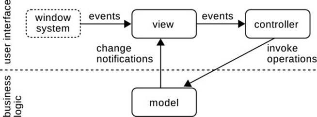
Figure 9.3 The Basic Model-View-Controller Pattern
The benefit of this additional split is mainly a stricter separation of concerns. We have seen in the discussion of the MEDIATOR that the event-listeners![]() 7.7 attached to widgets can quickly become complex in themselves. Moving this code into a self-contained object will keep the code of theview more focused on the visual presentation itself. Although many practical implementations reunite the two roles in the DOCUMENT-VIEW variant,
7.7 attached to widgets can quickly become complex in themselves. Moving this code into a self-contained object will keep the code of theview more focused on the visual presentation itself. Although many practical implementations reunite the two roles in the DOCUMENT-VIEW variant,![]() 9.2.8 is useful to consider them separately first, since this will lead to a clearer structure within the view component of this later development.
9.2.8 is useful to consider them separately first, since this will lead to a clearer structure within the view component of this later development.
In summary, the three roles of the pattern then perform these tasks:
• ![]() 9.1The model maintains the application’s data structures and algorithms, which constitute its business logic. The model is the valuable and stable core of the product; it is built to last through revisions and ports
9.1The model maintains the application’s data structures and algorithms, which constitute its business logic. The model is the valuable and stable core of the product; it is built to last through revisions and ports![]() 7.11 to different window systems. It builds on precise contracts and is thoroughly unit-tested.
7.11 to different window systems. It builds on precise contracts and is thoroughly unit-tested.
• The view renders the current state of the application data onto the screen. It accesses the model to retrieve the data, and registers as an observer to be notified about any changes and to keep the display![]() 7.1 up-to-date. By technical necessity, it also receives all user input as events and passes those events on to the controller.
7.1 up-to-date. By technical necessity, it also receives all user input as events and passes those events on to the controller.
• The controller interprets the user input events as triggers to perform operations and modifications on the model. It contains the logic for![]() 1.8.1 handling the events. In this role, it is a typical decision maker: It decides what needs to be done, but delegates the actual execution to others. In the basic pattern, this means calling the model’s methods.
1.8.1 handling the events. In this role, it is a typical decision maker: It decides what needs to be done, but delegates the actual execution to others. In the basic pattern, this means calling the model’s methods.
![]() The pattern describes all three roles as if they were filled by single objects. However, this is hardly ever the case: The application logic is usually implemented in a complex component with many helper objects that collaborate intensively, and even the view may need helpers to fulfill its task.
The pattern describes all three roles as if they were filled by single objects. However, this is hardly ever the case: The application logic is usually implemented in a complex component with many helper objects that collaborate intensively, and even the view may need helpers to fulfill its task.
To see the pattern in action, we implement a tiny widget that enables a single integer value to be incremented and decremented by clicking on![]() 7.5 different areas (Fig. 9.4). Rather than building a compound widget, we implement this from scratch to show all of the details.
7.5 different areas (Fig. 9.4). Rather than building a compound widget, we implement this from scratch to show all of the details.
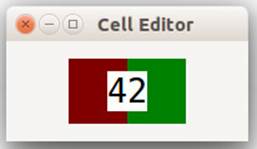
Figure 9.4 Minimal MVC Example
The model maintains the application data and supports observers.
![]() 9.1Following the earlier advice, we start with the model. Its “functionality” is to maintain a single integer value. To serve as a model in the pattern, the object also implements the OBSERVER pattern. The crucial point to be noted is that the model is in no way adapted to the intended presentation on the screen. In particular, the observers are merely notified that the content has changed (line 21); there is no indication that this notification will trigger a screen update later on.
9.1Following the earlier advice, we start with the model. Its “functionality” is to maintain a single integer value. To serve as a model in the pattern, the object also implements the OBSERVER pattern. The crucial point to be noted is that the model is in no way adapted to the intended presentation on the screen. In particular, the observers are merely notified that the content has changed (line 21); there is no indication that this notification will trigger a screen update later on.
celledit.mvc.IntCell
1 public class IntCell {
2 private int content;
3 private EventListenerList listeners = new EventListenerList();
4 public void addCellListener(CellListener l) {
5 ...
6 }
7 public void removeCellListener(CellListener l) {
8 ...
9 }
10 public int get() {
11 return content;
12 }
13 public void set(int cnt) {
14 int old = content;
15 this.content = cnt;
16 fireCellChanged(old);
17 }
18 protected void fireCellChanged(int old) {
19 for (CellListener l : listeners.getListeners(
20 CellListener.class))
21 l.cellChanged(this, old, content);
22 }
23 }
The view displays the data on the screen.
The view in the pattern must paint on the screen, so it derives from Canvas.![]() 7.8 It keeps references to the current model and controller, as well as the (larger)
7.8 It keeps references to the current model and controller, as well as the (larger)![]() 7.4.1 font used for painting and the computed preferred size.
7.4.1 font used for painting and the computed preferred size.![]() 7.1
7.1
celledit.mvc.View
public class View extends Canvas {
private IntCell model;
private Controller controller;
private Font fnt;
private Point sizeCache;
...
}
The main task of the view is to render the application data on the![]() 7.8 screen. The following excerpt from the painting method gives the crucial point: Line 3 gets the current value from the model and transforms it into a string to be drawn on the screen in line 7. The remaining code serves to center the string in the widget (bounds is the area available for painting).
7.8 screen. The following excerpt from the painting method gives the crucial point: Line 3 gets the current value from the model and transforms it into a string to be drawn on the screen in line 7. The remaining code serves to center the string in the widget (bounds is the area available for painting).
celledit.mvc.View
1 private void paintControl(PaintEvent e) {
2 ... paint red and green fields
3 String text = Integer.toString(model.get());
4 Point sz = g.textExtent(text);
5 int x = bounds.width / 2 - sz.x / 2;
6 int y = bounds.height / 2 - sz.y / 2;
7 g.drawString(text, x, y);
8 }
9
The view keeps the display up-to-date by observing the model.
To keep the display up-to-date, the view must observe the model. Whenever the model changes, the view observes the new model.
celledit.mvc.View
public void setModel(IntCell c) {
if (this.model != null)
this.model.removeCellListener(modelListener);
this.model = c;
if (this.model != null)
this.model.addCellListener(modelListener);
}
![]() Do not forget to detach the view from the model when the view is disposed. This
Do not forget to detach the view from the model when the view is disposed. This![]() 7.4.1 can be achieved reliably by setting the model to null in a DisposeListener.
7.4.1 can be achieved reliably by setting the model to null in a DisposeListener.
![]() 7.8The modelListener merely requests a complete repainting of the widget. In many scenarios, this is too inefficient for production use, so that
7.8The modelListener merely requests a complete repainting of the widget. In many scenarios, this is too inefficient for production use, so that![]() 9.4.3 incremental repainting must be implemented. To demonstrate the pattern, the simple choice is sufficient.
9.4.3 incremental repainting must be implemented. To demonstrate the pattern, the simple choice is sufficient.
celledit.mvc.View
private CellListener modelListener = new CellListener() {
public void cellChanged(IntCell cell, int oldVal, int newVal) {
redraw();
}
};
The view forwards user input to the controller.
Finally, the view must forward the events to the controller. This is usually achieved by registering the controller as an event-listener. For the current example, we delegate the actual registration to the controller itself to demonstrate an exchange of the controller later on.![]() 9.2.7
9.2.7
celledit.mvc.View.setController
public void setController(Controller c) {
if (controller != null)
controller.detach(this);
controller = c;
if (controller != null)
controller.attach(this);
}
Having finished with the model and the view, we have set up the main axis of Fig. 9.3: The display on the screen will always reflect the current data, independent of how that data will be manipulated. We will now add this last aspect by implementing the controller.
The controller receives all relevant user input.
The controller must receive all user input relevant to the expected reactions. Since the input is technically sent to the view, the controller registers itself as a listener on the view. In the current example, it becomes a mouse-listener to receive the clicks that will trigger the increment and decrement operations. (The super call merely remembers the view in a field view.)
celledit.mvc.MouseController.attach
public void attach(View view) {
super.attach(view);
this.view.addMouseListener(this);
this.view.addMouseTrackListener(this);
this.view.addMouseMoveListener(this);
}
The controller interprets the events as operations on the model.
The summary of tasks given earlier states that the purpose of the controller is to translate raw input events into operations on the model. The implementation can be seen in the callback methods for mouse clicks. The controller accesses the model to be operated on (lines 2–3) and checks which![]() 9.2.3 area the click actually occurred in (lines 4 and 7). Based on this information, it decides whether the model value should be incremented or decremented (lines 6 and 8). As a detail, the controller decides not to decrement the value if it has already reached 0.
9.2.3 area the click actually occurred in (lines 4 and 7). Based on this information, it decides whether the model value should be incremented or decremented (lines 6 and 8). As a detail, the controller decides not to decrement the value if it has already reached 0.
celledit.mvc.MouseController.mouseUp
1 public void mouseUp(MouseEvent e) {
2 if (view.getModel() != null) {
3 IntCell m = view.getModel();
4 if (view.isInDecrementArea(new Point(e.x, e.y)) &&
5 m.get() > 0)
6 m.set(m.get() - 1);
7 else if (view.isInIncrementArea(new Point(e.x, e.y)))
8 m.set(m.get() + 1);
9 }
10 }
The pattern processes input through view, controller, and model.
The overall goal of the MODEL-VIEW-CONTROLLER pattern can also be seen by tracing the user input through the different roles, until an actual screen update occurs.
1. The view receives the input and hands it to the controller.
2. The controller decides which action to take on the model.
3. The model performs the invoked operation and sends the resulting changes to the view, as one of possibly several observers.
4.![]() 9.4.3 The view interprets the model changes and decides which parts of the screen need to be redrawn.
9.4.3 The view interprets the model changes and decides which parts of the screen need to be redrawn.
5. The view refetches the relevant data and paints it on the screen.
This sequence of steps highlights the contributions of the different objects. It also points out that each of them can influence the final outcome: The view will contribute the visual appearance; the controller implements the reaction, since the view simply forwards events; and the model implements the functionality, but does not see the input events.
The central point of model-view separation is seen in steps 2 and 3. First, the controller alone is responsible for interpreting the input events; the model is not aware of the real causes of the invoked operations. Second, the model is not aware of the precise view class, or that there is a user interface at all; it merely supports the OBSERVER pattern.
9.2.2 Benefits of the Model-View-Controller Pattern
The MODEL-VIEW-CONTROLLER pattern is, in fact, rather complex and requires some extra implementation effort, compared to the naive solution of implementing the application’s functionality directly in event-listeners attached to the widgets. The investment into the extra structure and indirections introduced by the pattern must therefore be justified.
The user interface remains flexible.
The most important benefit of the pattern derives from its ability to keep the user interface flexible. Because the application’s functionality stays safe and sound in the model component and does not depend on the user interface in any way, it will remain valid if the interface changes. This can and will happen surprisingly often over the software’s lifetime.
The first reason for changing the user interface is the user. The central goal of a user interface is to support the users’ workflows effectively. As![]() 229 these workflows change or the users develop new preferences, the interface should ideally be adapted to match them. Also, different user groups may have different requirements, and new views may need to be developed as these requirements emerge. The MVC pattern confines such changes to the actual interface, unless the new workflows also require new computations and operations.
229 these workflows change or the users develop new preferences, the interface should ideally be adapted to match them. Also, different user groups may have different requirements, and new views may need to be developed as these requirements emerge. The MVC pattern confines such changes to the actual interface, unless the new workflows also require new computations and operations.
The second reason for changes relates to the underlying window system. When APIs change or new widgets or interaction devices are developed, the user interface must exploit them for the users’ benefit. Since these aspects are usually not related to the functionality in any way, the MVC keeps the application’s core stable.
Finally, it may be desirable to port the application to an entirely different platform. Here, the problem lies mostly in the user interface. In the best case, an analogous set of widgets will be available: Whether you access Windows, MacOS, GTK, or Qt, their widgets offer basically very similar services and events. Nevertheless, the user interface must usually be redeveloped from scratch. The MVC pattern ensures that the valuable core of the application, its functionality, will continue to work in the new environment, since this core uses only standard services such as file or network access, for which cross-platform APIs are available or where the platform differences can be hidden behind simple adapters.![]() 2.4.1
2.4.1
Multiple, synchronized views can better support the users’ workflows.
Modern IDEs such as Eclipse give us a good grasp on our source code. For example, while we work on the source in a text editor, we see an outline of its structure on the side. When we rename a method in one of the two windows, the other window reflects the change immediately. The reason is simply that both windows are, possibly through an indirection of the Java Model, views for the same text document, which fulfills the role of the view component in the MVC pattern. Similarly, Eclipse’s compiler reports an error only once by attaching an IMarker object to the file. The marker is reflected in the editor, the problems view, and as a small icon in the package explorer and project navigator.
The MODEL-VIEW-CONTROLLER pattern enables such synchronized views on the application’s data structure because views observe the model and are informed about its current state regardless of why changes have occurred.
The display remains up-to-date with the internal state.
At a somewhat more basic level, users will trust an application only if they are never surprised by its behavior. One common source of surprises is inconsistency between the internal data structures and the displayed data. The MVC pattern eliminates this chance completely and ensures that the users always base their actions and decisions on the most up-to-date information about the internal structures.
The application’s functionality remains testable.
![]() 5.4The single most important technique for making a system reliable and keeping it stable under change is testing. By making the functional core, the model, independent of a user interface, its operations can also be exercised in a testing fixture (see Fig. 5.1 on page 246) and its resulting state can be examined by simple assertions in unit tests. Testing the user interface,
5.4The single most important technique for making a system reliable and keeping it stable under change is testing. By making the functional core, the model, independent of a user interface, its operations can also be exercised in a testing fixture (see Fig. 5.1 on page 246) and its resulting state can be examined by simple assertions in unit tests. Testing the user interface,![]() 5.3.5 in contrast, is much more complex. Since the user interface itself tends to change very often, the effort of adapting the existing test cases and creating new ones will be considerable. The functional core, in contrast, is built to remain stable, so that the investment of testing will pay off easily.
5.3.5 in contrast, is much more complex. Since the user interface itself tends to change very often, the effort of adapting the existing test cases and creating new ones will be considerable. The functional core, in contrast, is built to remain stable, so that the investment of testing will pay off easily.
Model-view separation enables protection of the system’s core.
The stability of an application’s functionality relies heavily on precise contracts.![]() 4.1 Within this reasoning framework, each method trusts its callers to fulfill the stated pre-condition—that is, to pass only legal arguments and
4.1 Within this reasoning framework, each method trusts its callers to fulfill the stated pre-condition—that is, to pass only legal arguments and![]() 4.5 to call the method only in legal object states. The non-redundancy principle condenses the idea of trust into the development practice of never
4.5 to call the method only in legal object states. The non-redundancy principle condenses the idea of trust into the development practice of never![]() 4.6
4.6 ![]() 1.5.2 checking pre-conditions. At the system boundary, in contrast, the code can never trust the incoming data and requests. Methods must be written to be robust, and to check whether they really do apply.
1.5.2 checking pre-conditions. At the system boundary, in contrast, the code can never trust the incoming data and requests. Methods must be written to be robust, and to check whether they really do apply.
Model-view separation offers the benefits of localizing these necessary checks in the user interface component and maintaining the functional core in the clean and lean style enabled by the non-redundancy principle.
9.2.3 Crucial Design and Implementation Constraints
![]() 2.1.2As with the OBSERVER pattern, the concrete implementation of the MODEL-VIEW-CONTROLLER pattern must observe a few constraints to obtain the
2.1.2As with the OBSERVER pattern, the concrete implementation of the MODEL-VIEW-CONTROLLER pattern must observe a few constraints to obtain the![]() 9.2.2 expected benefits. We list here those aspects that we have found in teaching to make the difference between the code of novices and that of professionals.
9.2.2 expected benefits. We list here those aspects that we have found in teaching to make the difference between the code of novices and that of professionals.
Do not tailor the OBSERVER pattern to a specific view.
The first aspect is the definition of the Observer interface for the model. Especially when dealing with complex models and the necessity of incremental![]() 9.4.3 screen updates, there is always the temptation to “tweak” the change notifications a bit to simplify the logic that determines which parts of the screen need to be updated. Certainly, one should use the “push” variant of the Observer pattern; that is, the change notifications should be very detailed to
9.4.3 screen updates, there is always the temptation to “tweak” the change notifications a bit to simplify the logic that determines which parts of the screen need to be updated. Certainly, one should use the “push” variant of the Observer pattern; that is, the change notifications should be very detailed to![]() 2.1.3 enable any view to work efficiently regardless of its possible complexity.
2.1.3 enable any view to work efficiently regardless of its possible complexity.
When targeting the messages at specific views, however, one endangers the ability to add a new view or to change the existing one, or to port the application to an entirely different platform. Suppose, for instance, that the model manages a list of objects with some properties. It should then send a change message containing a description of the change. However, it should not use a message updateTableRow() simply because the current view is a Table widget. A better choice is a message changedData(), which reflects the change instead of the expected reaction. If the view displays the properties in a specific order, the model must not send messages update Table(int row, int col), but rather changedData(DataObject obj, String property). Even if this means that the view must map objects to rows and the property names to column indices, it increases the likelihood that the view can change independently of the model.
The controller never notifies the view about triggered operations.
A second shortcut that one may be tempted to take is to let the controller notify the view directly about any changes it has performed on the model, rather than going through the indirection via the model. First, this shortcut is marginally more efficient at runtime. What is particularly attractive, however, is that it saves the implementation of the general OBSERVER pattern![]() 2.1.4 tern in the model and the perhaps complex logic for translating changes to screen updates in the view.
2.1.4 tern in the model and the perhaps complex logic for translating changes to screen updates in the view.
However, the shortcut really destroys the core of the pattern, and nearly all of its benefits. One can no longer have multiple synchronized views. Also, the information on the screen may no longer be up-to-date if the controller neglects internal side effects and dependencies of the model. Finally, the![]() 9.4.2 logic for the updates must be duplicated in ports and variations of the user interface.
9.4.2 logic for the updates must be duplicated in ports and variations of the user interface.
The controller delegates decisions about the visual appearance to the view.
A comparatively minor point concerns the relationship between the view and the controller. If these roles are implemented as different objects at any![]() 9.2.8 point, then one should also strive for a strict separation of concerns—for instance, to keep the controller exchangeable.
9.2.8 point, then one should also strive for a strict separation of concerns—for instance, to keep the controller exchangeable.![]() 9.2.7
9.2.7
One notable aspect is the possible assumptions about the visual appearance. The controller often receives events that relate back to that visual appearance. For instance, a mouse click happens at a particular point on the screen, and the visual element at this point must determine the correct![]() 12.1.2 reaction. If the controller makes any assumptions about this visual element, it is tied to the specific implementation of the view. If several controllers exist, then it becomes virtually impossible to change even simple things such as the font size and spacing, since several controllers would have to change as well.
12.1.2 reaction. If the controller makes any assumptions about this visual element, it is tied to the specific implementation of the view. If several controllers exist, then it becomes virtually impossible to change even simple things such as the font size and spacing, since several controllers would have to change as well.
![]() 9.2.1 In the following tiny example, we have therefore made the controller ask the model whether the click event e occurred in one of the designated “active” areas. The controller now assumes the existence of these areas, but it does not know anything about their location and shape. That knowledge is encapsulated in the view and can be adapted at any time.
9.2.1 In the following tiny example, we have therefore made the controller ask the model whether the click event e occurred in one of the designated “active” areas. The controller now assumes the existence of these areas, but it does not know anything about their location and shape. That knowledge is encapsulated in the view and can be adapted at any time.
celledit.mvc.MouseController.mouseUp
if (view.isInDecrementArea(new Point(e.x, e.y)) && m.get() > 0)
m.set(m.get() - 1);
else if (view.isInIncrementArea(new Point(e.x, e.y)))
m.set(m.get() + 1);
![]() 9.2.8Even in the common DOCUMENT-VIEW variant of the MVC, where view and controller are implemented together in one object, it is still useful to obey the guideline by separating the concerns into different methods of the object.
9.2.8Even in the common DOCUMENT-VIEW variant of the MVC, where view and controller are implemented together in one object, it is still useful to obey the guideline by separating the concerns into different methods of the object.
The controller shields the model from the user input.
![]() 1.5.2
1.5.2 ![]() 4.6 The user interface is, of course, one of the system’s boundaries. Accordingly, all user input must be treated with suspicion: Has the user really entered valid data? Has the user clicked a button only when it makes sense? Does the selected file have the expected format?
4.6 The user interface is, of course, one of the system’s boundaries. Accordingly, all user input must be treated with suspicion: Has the user really entered valid data? Has the user clicked a button only when it makes sense? Does the selected file have the expected format?
Many of these questions are best handled in the controller, because it is the controller that receives the user input and decides which model![]() 7.11 operations need to be called in response. Since the model is built according to
7.11 operations need to be called in response. Since the model is built according to![]() 4.5 the principles of design by contract, it does not check any stated preconditions. It is the controller’s task to ensure that only valid method calls are made.
4.5 the principles of design by contract, it does not check any stated preconditions. It is the controller’s task to ensure that only valid method calls are made.
9.2.4 Common Misconceptions
The MODEL-VIEW-CONTROLLER pattern is rather complex, so it is not surprising that a few misunderstandings arise when first thinking it through. We have found in teaching that some misunderstandings tend to crop up repeatedly. They seem to arise mostly from the correct impression that![]() 12.2 the MVC is all about exchangeability and flexibility. However, one has to be careful about what really is exchangeable in the end and must not conclude that “all components can be exchanged and adapted to the users’ requirements.” We hope that highlighting the nonbenefits of the pattern in this section will enhance the understanding of the benefits that it does create.
12.2 the MVC is all about exchangeability and flexibility. However, one has to be careful about what really is exchangeable in the end and must not conclude that “all components can be exchanged and adapted to the users’ requirements.” We hope that highlighting the nonbenefits of the pattern in this section will enhance the understanding of the benefits that it does create.
Model-view separation is not a panacea.
The rather extensive mechanisms and logic necessary for establishing a proper model-view separation must always be seen as an investment. It is an investment that pays off quite quickly, even for medium-sized applications, but it is still an investment. The decision for or against using the MVC must therefore be based on a precise understanding of it benefits, so as to relate them to the application at hand. A small tool written for one project only will never need porting, for example, and if the developer is also its only user, there is little chance of having to change the user interface. A general understanding that the MVC offers “everything that can be wished for” is not enough.
The model is not exchangeable and the view is not reusable.
The view and the controller necessarily target a specific model: They ask the model for data and draw exactly that data; the view registers as an observer and expects certain kinds of change messages; and the controller translates user gestures into specific operations offered by the model. As a result, the model cannot usually be exchanged for a different one; by switch of perspective, this means that the view is usually not reusable.
Of course, it is still possible to implement generic widgets that access the model only through predefined interfaces. For instance, a table on the screen has rows, and the data in each row provides strings for each column. Both JFace and Swing provide excellent examples of generic and reusable![]() 9.3.1
9.3.1 ![]() 80 tables. However, this is an exercise in library or framework design. To build a concrete user interface, one has to supply adapters that link the generic mechanisms to the specific application model, and one has to implement listeners for generic
80 tables. However, this is an exercise in library or framework design. To build a concrete user interface, one has to supply adapters that link the generic mechanisms to the specific application model, and one has to implement listeners for generic![]() 2.4.1 table events that target the specific available model operations. In this perspective, the generic table is only a building block, not the complete user interface in the sense of the MVC.
2.4.1 table events that target the specific available model operations. In this perspective, the generic table is only a building block, not the complete user interface in the sense of the MVC.
The controller is usually neither exchangeable nor reusable.
The controller interprets user gestures, such as mouse moves, mouse clicks, and keyboard input. These gestures have a proper meaning, and hence a reliable translation to model operations, only with respect to the concrete visual appearance of the view. It is therefore usually not possible to reuse a controller on a different view. Exchanging the controller is possible, but![]() 9.2.7 only within the confines of the event sources offered by the view.
9.2.7 only within the confines of the event sources offered by the view.
9.2.5 Behavior at the User Interface Level
Effective user interfaces allow the user to invoke common operations by small gestures. For example, moving a rectangle in a drawing tool takes a mouse click to select the rectangle and a drag gesture to move it. Since many similarly small gestures have similarly small but quite different effects, the application must provide feedback so that the user can anticipate the reaction. For instance, when selecting a rectangle, it acquires drag handles—that is, a visual frame that indicates moving and resizing gestures will now influence this object.
Implement user feedback without participation of the model.
The important point to realize is that feedback is solely a user interface 'margin-top:4.0pt;margin-right:0cm;margin-bottom:4.0pt; margin-left:0cm;text-indent:15.0pt;line-height:normal'>![]() 9.2.1 Suppose, for instance, that we wish to enhance the example widget with the feedback shown in Fig. 9.5. When the mouse cursor is inside the widget, a frame appears to indicate this fact (a versus b and c); furthermore, a slightly lighter hue indicates whether a click would increment or decrement the counter (b versus c), and which field is the current target of the click.
9.2.1 Suppose, for instance, that we wish to enhance the example widget with the feedback shown in Fig. 9.5. When the mouse cursor is inside the widget, a frame appears to indicate this fact (a versus b and c); furthermore, a slightly lighter hue indicates whether a click would increment or decrement the counter (b versus c), and which field is the current target of the click.
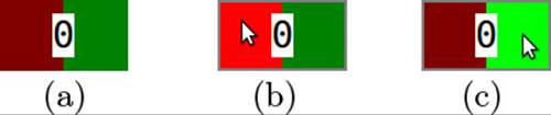
Figure 9.5 User-Interface Behavior: Mouse Feedback
Feedback is triggered by the controller.
The second aspect of feedback concerns the question of which role will actually decide which feedback needs to be shown. The answer here is clear: Because the controller will finally decide which operation is triggered on the model, it must also decide which feedback must be shown to apprise the user of this later behavior. It is similarly clear that the controller will decide on the feedback but will delegate the actual display to the view.
In the implementation of the example, the Controller tracks both the general mouse movements into and out of the widget, and the detailed movements inside the widget. The reaction to the mouseEnter and mouseExit events is straightforward: Just tell the view to draw the frame or to remove it. When the mouse leaves the widget, any target highlight must, of course, also be removed. The mouseMove proceeds in parallel to the![]() 9.2.1 mouseUp method in the basic implementation: It checks which operation it would perform and sets the corresponding highlight.
9.2.1 mouseUp method in the basic implementation: It checks which operation it would perform and sets the corresponding highlight.
celledit.mvc.MouseController
public void mouseEnter(MouseEvent e) {
view.setInside(true);
}
public void mouseExit(MouseEvent e) {
view.setInside(false);
view.setTargetField(View.TARGET_NONE);
}
public void mouseMove(MouseEvent e) {
if (view.isInDecrementArea(new Point(e.x, e.y)))
view.setTargetField(View.TARGET_DECREMENT);
else if (view.isInIncrementArea(new Point(e.x, e.y)))
view.setTargetField(View.TARGET_INCREMENT);
else
view.setTargetField(View.TARGET_NONE);
}
![]() The naming of the View methods is worth mentioning. They publish the fact that some visual effect can be achieved, but the effect itself remains a private decision of the View. This parallels the earlier implementation of mouseUp, where the controller did not know the exact shape of the clickable areas within the view.
The naming of the View methods is worth mentioning. They publish the fact that some visual effect can be achieved, but the effect itself remains a private decision of the View. This parallels the earlier implementation of mouseUp, where the controller did not know the exact shape of the clickable areas within the view.
![]() We said earlier that mouseExit must “of course” remove any target highlight. The question is whether this must be as explicit as in the code shown here: Would it not be better if the call setInside(false) would also remove the target highlight? In other words, shouldn’t the connection between the feedback mechanisms already be established within the View class? It would certainly make the controller’s methods simpler and more symmetric, and it would ensure a certain consistency within the view. We have chosen the variant in the example to emphasize that all decisions about feedback lie with the controller. In practical implementations, the other options can, however, be equally valid.
We said earlier that mouseExit must “of course” remove any target highlight. The question is whether this must be as explicit as in the code shown here: Would it not be better if the call setInside(false) would also remove the target highlight? In other words, shouldn’t the connection between the feedback mechanisms already be established within the View class? It would certainly make the controller’s methods simpler and more symmetric, and it would ensure a certain consistency within the view. We have chosen the variant in the example to emphasize that all decisions about feedback lie with the controller. In practical implementations, the other options can, however, be equally valid.
Feedback usually requires special state in the view.
In implementing the actual visual feedback within the View, we have to take into account one technical detail: Painting always occurs in a callback,![]() 7.8 at some arbitrary point that the window system deems suitable. The view must be ready to draw both the data and the feedback at that point. We therefore introduce special state components in the view:
7.8 at some arbitrary point that the window system deems suitable. The view must be ready to draw both the data and the feedback at that point. We therefore introduce special state components in the view:
celledit.mvc.View
private boolean inside = false;
public static final int TARGET_NONE = 0;
public static final int TARGET_DECREMENT = 1;
public static final int TARGET_INCREMENT = 2;
private int targetField = TARGET_NONE;
The View publishes the new state, but only to its related classes, such as the Controller. The setter for the state stores the new value and invokes![]() 7.8 redraw() to request a later painting operation. Since this is potentially expensive, one should always check whether the operation is necessary at all.
7.8 redraw() to request a later painting operation. Since this is potentially expensive, one should always check whether the operation is necessary at all.
celledit.mvc.View
protected void setInside(boolean inside) {
if (this.inside == inside)
return;
this.inside = inside;
redraw();
}
The actual painting then merely checks the current feedback state at the right point and creates the visual appearance. Here is the example for highlighting the “decrement” field; the increment field and the “inside” indications are similar.
celledit.mvc.View
private void paintControl(PaintEvent e) {
...
if (targetField == TARGET_DECREMENT)
g.setBackground(getDisplay().getSystemColor(SWT.COLOR_RED));
else
g.setBackground(getDisplay().getSystemColor(
SWT.COLOR_DARK_RED));
g.fillRectangle(bounds.x, bounds.y, bounds.width / 2,
bounds.height);
...
}
Separate view-level state from the application functionality.
The example of the feedback given here has introduced the necessity of state that only lives at the view level but does not concern the application’s core data structures. A plethora of similar examples comes to mind immediately: the selection in a text viewer or the selected row in a table; the folding and unfolding of nodes in a tree-structured display, such as SWT’s Tree; the currently selected tool in an image editor; the position of scrollbars in a list and the first row shown in consequence; the availability of buttons depending on previous choices; and many more.
In the end, the view-level state and the model-level state must be merged in one consistent user interface with predictable behavior. Internally, however, the two worlds must be kept separate: The one part of the state is thrown away, and the other must be stable when the interface changes; the one part is best tested manually, and the other must be rigorously unit-tested. Consequently, one must decide for each aspect of the overall state to which of the worlds it will belong.
The decision may seem rather obvious at first, but some cases might merit deeper discussions and sometimes one may have second thoughts about a decision. For instance, the GIMP image editor treats the selection as part of the model: You can undo and redo selection steps, and the selection![]() 9.5 even gets saved to the .xcf files. The reason is, obviously, that in the image manipulation domain, selection is often a key operation, and several detailed selection steps must be carried out in sequence to achieve a desired result. Being able to undo and redo selection helps users to remedy mistakes in the process.
9.5 even gets saved to the .xcf files. The reason is, obviously, that in the image manipulation domain, selection is often a key operation, and several detailed selection steps must be carried out in sequence to achieve a desired result. Being able to undo and redo selection helps users to remedy mistakes in the process.
9.2.6 Controllers Observing the Model
In the basic MODEL-VIEW-CONTROLLER pattern, the view necessarily observes![]() 9.2.1 the model, because it must translate any changes in the data to updates of the display. In many scenarios, the controller will also observe the model.
9.2.1 the model, because it must translate any changes in the data to updates of the display. In many scenarios, the controller will also observe the model.
Controllers can observe the model to indicate availability of operations.
A typical example of this behavior is seen in menu items that get grayed out if an operation is not available. For instance, a text editor will gray out the “copy” and “cut” entries if there is currently no selection.
The controller decides on the availability of operations.
It might be tempting to integrate the feedback on available actions directly into the view. After all, the view already observes the model and it can just as well handle one more aspect while it is at work anyway. However, since the controller decides which operations it will invoke for which user input, it is also the controller which decides whether these operations are currently available.
Suppose, for instance, that we wish to gray out the decrement field if the current count is already 0. This requires an extension of both the View and the Controller classes: The view acquires a new bit-mask stating which of the fields need to be grayed out, and that information is used when choosing the background color in paintControl(). The controller observes the model and switches the “gray” flags of the fields according to the current model value.
![]() You might ask whether to bother graying out the “increment” field at all, since the widget’s behavior does not assume an upper bound. We feel that keeping the implementation slightly more general and symmetric at very little cost at this point might help in future extensions. After all, similar widgets such as Slider and ScrollBar all do have upper limits.
You might ask whether to bother graying out the “increment” field at all, since the widget’s behavior does not assume an upper bound. We feel that keeping the implementation slightly more general and symmetric at very little cost at this point might help in future extensions. After all, similar widgets such as Slider and ScrollBar all do have upper limits.
Controllers must assume that others modify the model.
One possible pitfall that leads to nonprofessional code lies in the fact that the controller modifies the model itself and therefore seems to know precisely whether an operation causes some action to become unavailable. However, it should be noted that the MVC is built to support multiple synchronized views, and that other controllers may invoke model operations as well. Each controller that depends on the model’s state must therefore observe the model.
9.2.7 Pluggable Controllers
![]() 9.2.8Even if, as we shall see shortly, the view and controller are often coupled so tightly that it is sensible to implement them in a single object, it is still
9.2.8Even if, as we shall see shortly, the view and controller are often coupled so tightly that it is sensible to implement them in a single object, it is still![]() 146 instructive to consider briefly the concept of making the controller of a view pluggable to implement new interactions with an existing graphical presentation. This flexibility can be achieved only after understanding precisely the division of responsibilities between view and controller.
146 instructive to consider briefly the concept of making the controller of a view pluggable to implement new interactions with an existing graphical presentation. This flexibility can be achieved only after understanding precisely the division of responsibilities between view and controller.
So, let us implement a controller that enables the user to access the![]() 9.2.1 number entry field from the introductory example (Fig. 9.4 on page 455) via the keyboard. The new KeyboardController waits for keyboard input and modifies the model accordingly. Since the view observes the model, the change will become visible to the user.
9.2.1 number entry field from the introductory example (Fig. 9.4 on page 455) via the keyboard. The new KeyboardController waits for keyboard input and modifies the model accordingly. Since the view observes the model, the change will become visible to the user.
celledit.mvc.KeyboardController.keyReleased
public void keyReleased(KeyEvent e) {
IntCell m = view.getModel();
switch (e.character) {
case '+':
m.set(m.get() + 1);
break;
case '-':
if (m.get() > 0)
m.set(m.get() - 1);
break;
}
...
}
Keyboard input is different from mouse input in that it is not the current location of some cursor, but the keyboard focus of the window system (and SWT) that determines which widget will receive the events. The keyboard focus is essentially a pointer to that target widget, but it has interactions![]() 7.6 with the window manager (because of modal dialogs) and the tab order of widgets in the window. It is therefore necessary to display feedback to the users so that they know which reaction to expect when they press a key. The new controller therefore registers as aFocusListener of the View.
7.6 with the window manager (because of modal dialogs) and the tab order of widgets in the window. It is therefore necessary to display feedback to the users so that they know which reaction to expect when they press a key. The new controller therefore registers as aFocusListener of the View.
celledit.mvc.KeyboardController.attach
public void attach(View view) {
...
view.addFocusListener(this);
}
The controller then uses the existing “inside” indication on the view for the actual feedback:
celledit.mvc.KeyboardController
public void focusGained(FocusEvent e) {
view.setInside(true);
}
public void focusLost(FocusEvent e) {
view.setInside(false);
}
Another convention is that clicking on a widget with the mouse will give it the focus. This is, however, no more than a convention, and the widget itself has to request the focus when necessary. This reaction can be implemented directly. (Note that the actual indication that the focus has been obtained is shown indirectly, through the event-listener installed previously.)
celledit.mvc.KeyboardController.mouseUp
public void mouseUp(MouseEvent e) {
view.setFocus();
}
Finally, it is also useful to give a visual indication, in the form of a short flash of the respective increment/decrement fields, when the user presses the “+” and the “-” keys. This, too, can be achieved with the existing feedback mechanisms. The keyReleased() event then resets the target field to “none.” The flash will therefore mirror precisely the user’s pressing of the respective key.
celledit.mvc.KeyboardController.keyPressed
public void keyPressed(KeyEvent e) {
switch (e.character) {
case '+':
view.setTargetField(View.TARGET_INCREMENT);
break;
case '-':
view.setTargetField(View.TARGET_DECREMENT);
break;
}
}
The new controller emphasizes the division of logic between the view and the controller: The display and highlights remain with the view, and the controller decides what needs to be done in reaction to incoming user input. It is this division that has enabled us to reuse the existing highlight mechanisms for new purposes.
You might, of course, be suspicious of this reuse: Was it just coincidence![]() 12.4 that the existing mechanisms worked out for the new controller? Reuse always requires anticipating the shape of possible application scenarios and keeping the supported ones lean at the cost of excluding others. In the current case, we would argue that the feedback mechanisms that the view provides match the user’s understanding of the widget: The user “activates” the widget by “zooming in,” either by the mouse or by the keyboard focus, and then “triggers” one of the increment and decrement areas. All of these interactions are then mirrored by the highlights.
12.4 that the existing mechanisms worked out for the new controller? Reuse always requires anticipating the shape of possible application scenarios and keeping the supported ones lean at the cost of excluding others. In the current case, we would argue that the feedback mechanisms that the view provides match the user’s understanding of the widget: The user “activates” the widget by “zooming in,” either by the mouse or by the keyboard focus, and then “triggers” one of the increment and decrement areas. All of these interactions are then mirrored by the highlights.
Nevertheless, it must be said that views and controllers usually depend heavily on each other, so that exchanging the controller is rarely possible.![]() 214 One example where it is enabled is found in the pluggable edit policies of the Graphical Editing Framework, which create a setup where reusable controller-like logic can be attached to various elements of the user interface in a flexible way.
214 One example where it is enabled is found in the pluggable edit policies of the Graphical Editing Framework, which create a setup where reusable controller-like logic can be attached to various elements of the user interface in a flexible way.
9.2.8 The Document-View Variant
The view and controller in the MVC pattern are usually connected very tightly: The controller can request only those events that the view provides, and it can make use of only those feedback mechanisms that the view implements. Since it is therefore often not possible to use either the view or the controller without the other, one can go ahead and implement both roles in the same object. This leads to the DOCUMENT-VIEW pattern, where the![]() 9.1 document contains the application logic and the view contains the entire user interface code. In this way, the interface code can share knowledge about the widget’s internals between the logic of the display and the event-listeners. This may facilitate coding and avoids having to design an API that enables the view and the controller classes to communicate.
9.1 document contains the application logic and the view contains the entire user interface code. In this way, the interface code can share knowledge about the widget’s internals between the logic of the display and the event-listeners. This may facilitate coding and avoids having to design an API that enables the view and the controller classes to communicate.
![]() 9.2.1 Let us examine this idea through the simple example of incrementing and decrementing an integer value. We start from a technical perspective.
9.2.1 Let us examine this idea through the simple example of incrementing and decrementing an integer value. We start from a technical perspective.![]() 7.8 Since we need to implement a widget with custom painting, the overall structure is that of a Canvas with attached listeners. The drawing part is actually the same as in the previous implementation. Only the code for the event-listeners is integrated. In the simplest case, we wait for mouse
7.8 Since we need to implement a widget with custom painting, the overall structure is that of a Canvas with attached listeners. The drawing part is actually the same as in the previous implementation. Only the code for the event-listeners is integrated. In the simplest case, we wait for mouse![]() 2.1.3 clicks. To avoid publishing this fact by making the View class implement MouseListener, we attach an anonymous listener that delegates to the outer class.
2.1.3 clicks. To avoid publishing this fact by making the View class implement MouseListener, we attach an anonymous listener that delegates to the outer class.
celledit.docview.View.View
addMouseListener(new MouseAdapter() {
public void mouseUp(MouseEvent e) {
handleMouseUp(e);
}
});
Keep the code for display and reaction loosely coupled.
On the first try, one is liable to take the freedom of “sharing knowledge” between display and event-listeners very literally. For instance, we know that paintComponent() draws the dividing line between the decrement and increment fields right in the middle of the widget’s screen space. The event-listener can therefore be written up like this:
celledit.docview.View
private void mouseUp1(MouseEvent e) {
Rectangle area = getClientArea();
if (cell.get() > 0 && area.width / 2 <= e.x &&
e.x <= area.width &&
0 <= e.y && e.y <= area.height)
cell.set(cell.get() - 1);
...
};
However, this is highly undesirable: It is not possible to change the visual appearance without going through the entire class and checking which code might be influenced. It is much better to introduce a private helper![]() 1.4.5 method that decides whether a particular point is in the increment or decrement fields. Placing this helper near the paintComponent()—that is, splitting the class logically between display and reaction code—will greatly facilitate maintenance.
1.4.5 method that decides whether a particular point is in the increment or decrement fields. Placing this helper near the paintComponent()—that is, splitting the class logically between display and reaction code—will greatly facilitate maintenance.
celledit.docview.View
private void handleMouseUp(MouseEvent e) {
if (cell.get() > 0 && isInDecrementArea(new Point(e.x, e.y)))
cell.set(cell.get() - 1);
...
};
private boolean isInDecrementArea(Point p) {
...
}
In the end, this implementation is very near the original division between view and controller. One crucial difference is that now the helper method is not an external API that may be accessed from the outside and must therefore be maintained, but rather a private, encapsulated detail that may be changed at any time without breaking other parts of the system.
With predefined widgets, access their API directly.
In many cases, the actual display consists of predefined widgets such as text fields or tables. These widgets already encapsulate all painting-related aspects so that it is not necessary to introduce helpers. The DOCUMENT-VIEW pattern then applies very directly, since listeners can get the content or the selection of widgets without further ado.
9.3 The JFace Layer
![]() 7.1SWT is a typical user interface toolkit that provides the standard interaction elements, such as text fields, tables, and trees, out of the box. However,
7.1SWT is a typical user interface toolkit that provides the standard interaction elements, such as text fields, tables, and trees, out of the box. However,![]() 7.4 it is also designed to be minimal: Since it accesses the native widgets of the platform that the application executes on, the SWT classes must be ported to every supported platform. For that reason, SWT offers only bare-bones functionality. Any higher-level functionality is factored out into the JFace framework, which is pure Java and portable. JFace facilitates connecting the application data structures to the existing SWT widgets, and is therefore indispensable for effective development of user interfaces. It also provides standard elements such as message dialogs and application windows equipped with a menu, toolbar, and status bar.
7.4 it is also designed to be minimal: Since it accesses the native widgets of the platform that the application executes on, the SWT classes must be ported to every supported platform. For that reason, SWT offers only bare-bones functionality. Any higher-level functionality is factored out into the JFace framework, which is pure Java and portable. JFace facilitates connecting the application data structures to the existing SWT widgets, and is therefore indispensable for effective development of user interfaces. It also provides standard elements such as message dialogs and application windows equipped with a menu, toolbar, and status bar.
From a conceptual point of view, JFace provides a complementary perspective on model-view separation. While usually the model is stable and the user interface remains flexible, JFace provides fixed but generic user interface components that connect flexibly to application-specific models. Studying its mechanisms will enhance the understanding of model-view separation itself.
![]() The JFace layer is contained in the bundle org.eclipse.jface, with extensions in
The JFace layer is contained in the bundle org.eclipse.jface, with extensions in![]() 9.3.3 org.eclipse.jface.databinding and org.eclipse.jface.text. For historical reasons, it also relies on some elements of org.eclipse.core.runtime, which can be used
9.3.3 org.eclipse.jface.databinding and org.eclipse.jface.text. For historical reasons, it also relies on some elements of org.eclipse.core.runtime, which can be used![]() 7.4.2 outside of the platform in just the way that we launched SWT applications as standard Java applications.
7.4.2 outside of the platform in just the way that we launched SWT applications as standard Java applications.
9.3.1 Viewers
![]() 12.2.2The basic approach of JFace is shown in Fig. 9.6(a). JFace establishes a layer between the application’s business logic and the bare-bones SWT widgets. JFace uses methods like setText and setIcon to actually display the data in widgets and registers for low-level events as necessary. It also offers events to the application itself, but these are special in that they translate from the widget level to the model level. For instance, when a user selects a row in a Table widget, SWT reports the index of the row. JFace translates that index into the model element it has previously rendered in the row, and reports that this model element has been selected. In effect, the application is shielded from the cumbersome details and can always work in terms of its own data structures. Of course, it still listens to events such as button clicks directly on the SWT widgets, and translates those into operations on
12.2.2The basic approach of JFace is shown in Fig. 9.6(a). JFace establishes a layer between the application’s business logic and the bare-bones SWT widgets. JFace uses methods like setText and setIcon to actually display the data in widgets and registers for low-level events as necessary. It also offers events to the application itself, but these are special in that they translate from the widget level to the model level. For instance, when a user selects a row in a Table widget, SWT reports the index of the row. JFace translates that index into the model element it has previously rendered in the row, and reports that this model element has been selected. In effect, the application is shielded from the cumbersome details and can always work in terms of its own data structures. Of course, it still listens to events such as button clicks directly on the SWT widgets, and translates those into operations on![]() 9.2.1 the model. JFace follows model-view separation in getting the data to be
9.2.1 the model. JFace follows model-view separation in getting the data to be![]() 9.1 displayed from the model and listening to change notifications of the model to keep the display up-to-date.
9.1 displayed from the model and listening to change notifications of the model to keep the display up-to-date.
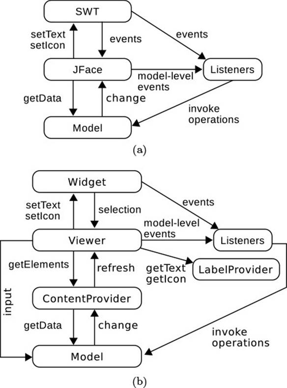
Figure 9.6 JFace Architecture
We will now discuss the various roles and relationships depicted in Fig. 9.6. This section focuses on the viewers and their collaborators. The listeners, which implement the application’s reactions to user input in the sense of controllers, are discussed in Section 9.3.2.![]() 9.2.1
9.2.1
JFace viewers target specific widget types.
A core contribution of the JFace layer relates to its selection of generic viewers, each of which targets a specific type of widget: A TableViewer targets Tables, a ComboViewer targets a Combo combo box, and so on [Fig. 9.6(b), at the top]. Viewers use the widget-specific methods for displaying data and listen for widget-specific events.
JFace viewers access the application data through adapters.
One question not addressed in Fig. 9.6(a) is how JFace will actually access the application-specific data: How is a generic viewer supposed to know the right getData method and the implementation of the OBSERVER pattern of the specific data structures? Fig. 9.6(b) supplies this detail. First, each viewer holds a reference to the model, in its property input. However, that input is a generic Object, so the viewer never accesses the model itself.![]() 1.3.4
1.3.4 ![]() 2.4.1 Instead, the viewer is parameterized by two adapter objects that enable it to inspect the model just as required:
2.4.1 Instead, the viewer is parameterized by two adapter objects that enable it to inspect the model just as required:
• The content provider is responsible for traversing the overall data structure and for splitting it up into elements for display purposes. For a table or list, it provides a linear sequence of elements; for a tree-like display, it also accesses the child and parent links between![]() 2.4.1 the elements. Furthermore, the content provider must observe the model and notify the viewer about any changes that it receives.
2.4.1 the elements. Furthermore, the content provider must observe the model and notify the viewer about any changes that it receives.
• The label provider is called back for each element delivered by the content provider, usually to obtain concrete strings and icons to represent the element on the screen. A ListViewer will request one text/icon combination per element; a TableViewer or TreeViewer will request one combination for each column. The viewer will also observe the label provider to be notified about changes of the text and icons to be displayed.
![]() The text-related viewers TextViewer and SourceViewer deviate from this schema in that they expect an implementation of IDocument as their model. The document itself then includes the text-specific access operations, without requiring a separate adapter.
The text-related viewers TextViewer and SourceViewer deviate from this schema in that they expect an implementation of IDocument as their model. The document itself then includes the text-specific access operations, without requiring a separate adapter.
![]() The framework includes a deliberate redundancy regarding changes in the model: When values change within a data element, then those may be translated for the viewer either by the content provider, by calling the viewer’s update() method, or by the label provider, by firing change events. Each mechanism has its merits. On the one hand, the content provider observes the model anyway, so the label provider can often remain passive. On the other hand, some generic label providers, such as those used in
The framework includes a deliberate redundancy regarding changes in the model: When values change within a data element, then those may be translated for the viewer either by the content provider, by calling the viewer’s update() method, or by the label provider, by firing change events. Each mechanism has its merits. On the one hand, the content provider observes the model anyway, so the label provider can often remain passive. On the other hand, some generic label providers, such as those used in![]() 9.3.3 data binding, may wish to avoid relying on specific content providers.
9.3.3 data binding, may wish to avoid relying on specific content providers.
Let us start with a simple example, in which an application accepts and monitors incoming TCP connections (Fig. 9.7). Whenever a new client connects, the corresponding information gets shown. When the client disconnects, its row is removed from the table.
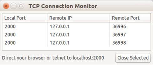
Figure 9.7 Connection Monitor
Keep the model independent of JFace.
We start by developing the model of the application, with the intention of keeping it independent of the user interface, and more specifically the![]() 9.1 JFace API. The model here maintains a list of connections (which contain a Socket as the endpoint of a TCP connection). Furthermore, it implements the OBSERVER pattern, which explains the registration (and omitted de-registration) of listeners (lines 13–16), as well as the fire method for notifying the listeners (lines 18–20). The method opened() and corresponding method closed() will be called back from the actual server code. Since that code runs in a separate thread, all access to the internal data structures
9.1 JFace API. The model here maintains a list of connections (which contain a Socket as the endpoint of a TCP connection). Furthermore, it implements the OBSERVER pattern, which explains the registration (and omitted de-registration) of listeners (lines 13–16), as well as the fire method for notifying the listeners (lines 18–20). The method opened() and corresponding method closed() will be called back from the actual server code. Since that code runs in a separate thread, all access to the internal data structures![]() 8.1 needs to be protected by locking. Finally, we decide that the notification of the observers can be performed in an open call (line 10), without holding
8.1 needs to be protected by locking. Finally, we decide that the notification of the observers can be performed in an open call (line 10), without holding![]() 8.5 on to the lock.
8.5 on to the lock.
connections.ConnectionList
1 public class ConnectionList {
2 private ArrayList<Connection> openConnections =
3 new ArrayList<Connection>();
4 private ListenerList listeners = new ListenerList();
5
6 void opened(Connection c) {
7 synchronized (this) {
8 openConnections.add(c);
9 }
10 fireConnectionOpened(c);
11 }
12 ...
13 public synchronized void addConnectionListListener(
14 ConnectionListListener l) {
15 listeners.add(l);
16 }
17 ...
18 protected void fireConnectionOpened(Connection c) {
19 ...
20 }
21 ...
22 }
![]() We use synchronized for locking because the simplicity of the use case makes it unlikely that we will ever need the flexibility of the library tools advocated in the
We use synchronized for locking because the simplicity of the use case makes it unlikely that we will ever need the flexibility of the library tools advocated in the![]() 8 chapter on multithreading.
8 chapter on multithreading.
The important point about the model is that it is independent of the user interface: It serves as a central list in which the server code manages the open connections, it synchronizes the different possible accesses, and it notifies interested observers. These observers are completely agnostic of a possible implementation in the user interface as well:
connections.ConnectionListListener
public interface ConnectionListListener extends EventListener {
void connectionOpened(ConnectionList p, Connection c);
void connectionClosed(ConnectionList p, Connection c);
}
This finishes the model in Fig. 9.6(b). We will now fill in the remaining bits.
Create the widget and its viewer together.
The viewer in Fig. 9.6(b) is linked tightly to its SWT widget: The type of widget is fixed, and each viewer can fill only a single widget, since it keeps track of which data it has displayed at which position within the widget. One therefore creates the viewer and the widget together. If a viewer is created without an explicit target widget, it will create the widget by itself.![]() 7.1 The viewer constructor also takes the parent widget and flags, as usual for SWT. The SWT widget is not encapsulated completely, since the display-related services, such as computing layouts, are accessed directly.
7.1 The viewer constructor also takes the parent widget and flags, as usual for SWT. The SWT widget is not encapsulated completely, since the display-related services, such as computing layouts, are accessed directly.
connections.Main.createContents
connectionsViewer = new TableViewer(shell, SWT.BORDER);
connections = connectionsViewer.getTable();
connections.setLayoutData(new GridData(
SWT.FILL, SWT.FILL, true, true,
2, 1));
connections.setHeaderVisible(true);
Connect the viewer to the model through a special content provider.
Each model has, of course, a different structure and API, so that each model will also require a new content provider class. The viewer then receives its own instance of that class.
connections.Main.createContents
connectionsViewer.setContentProvider(
new ConnectionListContentProvider());
The reason for this one-to-one match between content provider object and viewer object is that the content provider usually has to be linked up very tightly between the viewer and its input [Fig. 9.6(b)]. The life cycle of the content provider clarifies this. Whenever the viewer receives a new input, it notifies its content provider through the inputChanged() method. The method must also make sure to de-register from the previous input![]() 2.1.2 (lines 8–9). When the viewer is disposed, with the SWT widget, it calls the method again with a new input of null. The logic for de-registering from the old model therefore also kicks in at the end of the life cycle. At this point, the viewer calls the content provider’s dispose() method for any additional cleanup that may be necessary.
2.1.2 (lines 8–9). When the viewer is disposed, with the SWT widget, it calls the method again with a new input of null. The logic for de-registering from the old model therefore also kicks in at the end of the life cycle. At this point, the viewer calls the content provider’s dispose() method for any additional cleanup that may be necessary.
connections.ConnectionListContentProvider
1 public class ConnectionListContentProvider implements
2 IStructuredContentProvider, ConnectionListListener {
3 private ConnectionList list;
4 private TableViewer viewer;
5 public void inputChanged(Viewer viewer, Object oldInput,
6 Object newInput) {
7 this.viewer = (TableViewer) viewer;
8 if (list != null)
9 list.removeConnectionListListener(this);
10 this.list = (ConnectionList) newInput;
11 if (list != null)
12 list.addConnectionListListener(this);
13 }
14 public void dispose() {}
15 ...
16 }
![]() Line 7 in this code assumes that the viewer is a TableViewer. This can be justified by stating in the class’s contract that the content provider may be used only with that kind of viewer. The non-redundancy principle then decrees that line 7 must not
Line 7 in this code assumes that the viewer is a TableViewer. This can be justified by stating in the class’s contract that the content provider may be used only with that kind of viewer. The non-redundancy principle then decrees that line 7 must not![]() 4.5 check whether the contract is actually obeyed. Many content providers in the Eclipse code base are more defensive, or general, at this point and do something sensible for different kinds of viewers.
4.5 check whether the contract is actually obeyed. Many content providers in the Eclipse code base are more defensive, or general, at this point and do something sensible for different kinds of viewers.
The content provider knows how to traverse the model’s structure.
The content provider in Fig. 9.6(b) is an adapter that provides the interface expected by the JFace viewer on top of the application’s model. Designing this interface is an interesting task: Which kind of common structure can one expect to find on all models? The approach in JFace is to start from the minimal requirements of the TableViewer, as the (main) client: A table is![]() 3.2.2 a linear list of rows, so the viewer has to be able to get the data elements behind these table rows. In the current example, each row is a Connection and the model already provides a method to obtain the current list. The inputElement is the viewer’s input model passed to inputChanged(); passing it again enables stateless and therefore shareable content providers.
3.2.2 a linear list of rows, so the viewer has to be able to get the data elements behind these table rows. In the current example, each row is a Connection and the model already provides a method to obtain the current list. The inputElement is the viewer’s input model passed to inputChanged(); passing it again enables stateless and therefore shareable content providers.
connections.ConnectionListContentProvider.getElements
public Object[] getElements(Object inputElement) {
return ((ConnectionList) inputElement).getOpenConnections();
}
To see more of the idea of generic interface components, let us consider briefly a tree, rendered in a TreeViewer. A tree has more structure than a flat table: The single elements may have children, and all but the top-level elements have a parent. Tree-like widgets usually enable multiple top-level elements, rather than a single root, so that the content provider has the same method getElements() as the provider for flat tables.
org.eclipse.jface.viewers.ITreeContentProvider
public interface ITreeContentProvider
extends IStructuredContentProvider {
public Object[] getElements(Object inputElement);
public Object[] getChildren(Object parentElement);
public Object getParent(Object element);
public boolean hasChildren(Object element);
}
Now the JFace viewer can traverse the application model’s data structure by querying each element in turn. As long as the model has a table-like or tree-like structure, respectively, it will fit the expectations of the JFace layer. In general, each viewer expects a specific kind of content provider stated in its documentation, according to the visual structure of the targeted widget.
![]() You may find it rather irritating that all viewers offer only the generic method shown next, which does not give an indication of the expected type. The deeper reason is that it is in principle not possible to override a method and specialize its the parameter
You may find it rather irritating that all viewers offer only the generic method shown next, which does not give an indication of the expected type. The deeper reason is that it is in principle not possible to override a method and specialize its the parameter![]() 60 types, because thisco-variant overriding breaks polymorphism: A client that works with only the base class might unsuspectingly pass a too-general object. Java therefore requires overriding methods to have exactly the same parameter types.
60 types, because thisco-variant overriding breaks polymorphism: A client that works with only the base class might unsuspectingly pass a too-general object. Java therefore requires overriding methods to have exactly the same parameter types.
org.eclipse.jface.viewers.StructuredViewer
public void setContentProvider(IContentProvider provider)
![]() For simple display cases where the model does not change, one can also use the ArrayContentProvider, which accepts a List or an array and simply returns its
For simple display cases where the model does not change, one can also use the ArrayContentProvider, which accepts a List or an array and simply returns its![]() 1.3.8 elements. Since it does not have any state, it implements the Singleton pattern.
1.3.8 elements. Since it does not have any state, it implements the Singleton pattern.
The label provider decides on the concrete visual representation.
In the end, SWT shows most data on the screen as text, perhaps with auxiliary icons to give the user visual hints for interpreting the text, such as a green check mark to indicate success. The label provider attached to JFace viewers implements just this transformation, from data to text and icons. In the example, the table has three columns for the local port, the remote IP, and the remote port. All of this data is available from the Socket stored in the connection, so the label provider just needs to look into the right places and format the data into strings.
connections.ConnectionListLabelProvider
public class ConnectionListLabelProvider
extends LabelProvider
implements ITableLabelProvider {
...
public String getColumnText(Object element, int columnIndex) {
Connection c = (Connection) element;
switch (columnIndex) {
case 0: return Integer.toString(c.getLocalPort());
case 1: return c.getRemoteAddr().getHostAddress();
case 2: return Integer.toString(c.getRemotePort());
default:
throw new IllegalArgumentException();
}
}
}
![]() A corresponding getIcon() method remains empty here. If icons are allocated for
A corresponding getIcon() method remains empty here. If icons are allocated for![]() 7.4.1 the specific label provider, they must be freed in its dispose() method, which the viewer calls whenever the widget disappears from the screen.
7.4.1 the specific label provider, they must be freed in its dispose() method, which the viewer calls whenever the widget disappears from the screen.
![]() The base class LabelProvider, or actually its superclass BaseLabelProvider, implements an observer pattern that enables concrete label providers to notify viewers about changes in the choice of text or icon. Model changes are usually handled through the content provider, as seen next.
The base class LabelProvider, or actually its superclass BaseLabelProvider, implements an observer pattern that enables concrete label providers to notify viewers about changes in the choice of text or icon. Model changes are usually handled through the content provider, as seen next.
By separating the concerns of model traversal and the actual display, JFace gains flexibility. For instance, different viewers might show different aspects and properties of the same model, so that the same content provider can be combined with different label providers.
The viewer manages untyped Objects.
We have found that at this point it is useful to get a quick overview of the viewer’s mechanisms, so as to better appreciate the respective roles and the interactions of the viewer, the content provider, and the label provider. At the same time, these interactions illustrate the concept of![]() 11.1generic mechanisms, which will become fundamental in the area of frameworks
11.1generic mechanisms, which will become fundamental in the area of frameworks![]() 12.3 and for providing extensibility.
12.3 and for providing extensibility.
Fig. 9.8 shows what happens from the point where the application supplies the model until the data shows up on the screen. The input is forwarded to the content provider, which chops up the overall model into elements. The viewer passes each of these elements to the label provider and receives back a string. It then displays that string on the screen. For deeper structures, the viewer queries children of elements, and again hands each of these to the label provider, until the structure is exhausted.
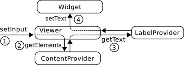
Figure 9.8 The Sequence for Displaying Data Through Viewers
In the end, the viewer’s role is to manage untyped objects belonging to the application’s model: It keeps references to the model and all elements as Objects. Whenever it needs to find out more about such an object, it passes the object to the content or label provider. In this way, the viewer can implement powerful generic display mechanisms without actually knowing anything about the application data.
Forward change notifications to the viewer.
We have now set up the display of the initial model. However, the model changes over the time, and it fires change notifications. Like any adapter [Fig. 2.10(b) on page 137], the content provider must also translate those notifications for the benefit of the viewer [Fig. 9.6(b)].
Toward that end, JFace viewers offer generic notification callbacks that reflect the possible changes in the abstract list or tree model that they envision in their content provider interface. A TableViewer, for instance, has callbacks for additions, insertions, deletions, and updates of single elements. The difference between update() and refresh() is that the first method locally recomputes the labels in a single table entry, while the latter indicates structural changes at the element, though it is relevant only for trees.
org.eclipse.jface.viewers.AbstractTableViewer
public void add(Object element)
public void insert(Object element, int position)
public void remove(Object element)
public void update(Object element, String[] properties)
public void refresh(Object element)
![]() Even though these methods are public as a technical necessity, they are not for general use but are intended for the content provider only. In particular, they do not add or remove the given elements from the underlying model.
Even though these methods are public as a technical necessity, they are not for general use but are intended for the content provider only. In particular, they do not add or remove the given elements from the underlying model.
![]() As a matter of optimization, viewers offer variants of these methods for bulk updates of several objects passed in an array. For large models, TableViewer and TreeViewer also support lazy population of the widget through the SWT.VIRTUAL flag passed to the constructor. In this case, the content provider can implement ILazyContentProvider or ILazyTreeContentProvider, respectively. The viewer will call the content provider only for rows that become visible—for instance, by scrolling or unfolding of tree nodes. The overhead of initially filling the entire widget is avoided.
As a matter of optimization, viewers offer variants of these methods for bulk updates of several objects passed in an array. For large models, TableViewer and TreeViewer also support lazy population of the widget through the SWT.VIRTUAL flag passed to the constructor. In this case, the content provider can implement ILazyContentProvider or ILazyTreeContentProvider, respectively. The viewer will call the content provider only for rows that become visible—for instance, by scrolling or unfolding of tree nodes. The overhead of initially filling the entire widget is avoided.
In the running example, connections can be added to and removed from the list of current connections. The content provider listens to these changes and notifies the viewer accordingly. Since the server uses several threads for the processing of client connections, the content provider must also switch![]() 7.10.1 to the event thread to notify the viewer.
7.10.1 to the event thread to notify the viewer.
connections.ConnectionListContentProvider.connectionOpened
public void connectionOpened(ConnectionList p, final Connection c) {
viewer.getControl().getDisplay().asyncExec(new Runnable() {
public void run() {
viewer.add(c);
}
});
}
![]() Swing’s JTable takes a different—and very interesting—approach to these notifications, which renders the idea of an “adapter” more clearly. Its method setModel()
Swing’s JTable takes a different—and very interesting—approach to these notifications, which renders the idea of an “adapter” more clearly. Its method setModel()![]() 2.4.1 accepts any implementation of TableModel, and that model must provide the OBSERVER
2.4.1 accepts any implementation of TableModel, and that model must provide the OBSERVER![]() 2.1 pattern for TableModelListeners. The generic JTable widget merely registers as one such listener. The JFace perspective, in contrast, is that the content provider is a close collaborator of a single viewer, which it notifies directly. This approach saves the effort of implementing the OBSERVER pattern.
2.1 pattern for TableModelListeners. The generic JTable widget merely registers as one such listener. The JFace perspective, in contrast, is that the content provider is a close collaborator of a single viewer, which it notifies directly. This approach saves the effort of implementing the OBSERVER pattern.![]() 2.1.4
2.1.4
Viewers provide higher-level services at the application level.
JFace viewers offer more services than just a mapping from application model to screen display. For instance, they enable the application code to work almost entirely at the level of the application model. Consequently, SWT widgets, for example, represent the concept of “selection” by publishing the indices of selected elements. JFace viewers, in contrast, publish IStructuredSelection objects, which are basically sets of model elements. Furthermore, viewers do not map elements directly, but perform preprocessing steps for filtering and sorting. As a final example, they implement mechanisms for inline editing: When the user clicks “into” a table cell, the table viewer creates a small overlay containing an application-specific![]() 7.6 CellEditor that fills the cell’s screen space but is, in fact, a stand-alone widget.
7.6 CellEditor that fills the cell’s screen space but is, in fact, a stand-alone widget.
![]()
![]() 9.1Sorting and filtering are interesting in themselves as an instance of model-view separation: The fact that a user prefers, in certain situations and for certain tasks, to see only a selection of elements in a particular order, must be dealt with independently of the core functionality—after all, the next view or the next user may have entirely
9.1Sorting and filtering are interesting in themselves as an instance of model-view separation: The fact that a user prefers, in certain situations and for certain tasks, to see only a selection of elements in a particular order, must be dealt with independently of the core functionality—after all, the next view or the next user may have entirely![]() 2.4.1 different preferences. For instance, Eclipse’s Java Model reflects the structure of the Java source code. The underlying abstract syntax tree keeps declarations in the order of their appearance within a class. At the interface level, the user may prefer seeing only public members or having the members be ordered alphabetically, as seen in the Package Explorer.
2.4.1 different preferences. For instance, Eclipse’s Java Model reflects the structure of the Java source code. The underlying abstract syntax tree keeps declarations in the order of their appearance within a class. At the interface level, the user may prefer seeing only public members or having the members be ordered alphabetically, as seen in the Package Explorer.
9.3.2 Finishing Model-View-Controller with JFace
![]() 9.2.1JFace viewers already cover much of the MODEL-VIEWER-CONTROLLER pattern, in that the screen reliably mirrors the state of the application’s functional core. The only missing aspect is that of controllers, which interpret the raw user input as requests for performing operations on the model. This will happen in the event-listeners shown in Fig. 9.6.
9.2.1JFace viewers already cover much of the MODEL-VIEWER-CONTROLLER pattern, in that the screen reliably mirrors the state of the application’s functional core. The only missing aspect is that of controllers, which interpret the raw user input as requests for performing operations on the model. This will happen in the event-listeners shown in Fig. 9.6.
JFace enables controllers to work on the application model.
Suppose that we wish to implement the button labeled “Close” in Fig. 9.7. Since the button itself is an SWT widget independent of any viewer, we![]() 7.1 attach a listener as usual:
7.1 attach a listener as usual:
connections.Main.createContents
Button btnClose = new Button(shell, SWT.NONE);
btnClose.addSelectionListener(new SelectionAdapter() {
public void widgetSelected(SelectionEvent e) {
handleCloseSelected();
}
});
The method handleCloseSelected() then relies heavily on support from JFace. Line 3 retrieves the viewer’s selection, which maps the indices of rows selected in the table widget to the model elements shown in those rows. As a result, line 5 can ask for the first (and only) selected element and be sure to obtain a Connection, because the viewer’s content provider![]() 9.3.1 has delivered instances of only that class. The crucial point now is that the actual logic for implementing the desired reaction in line 7 remains at the application level: The model’s Connectionobjects also offer a method close() for terminating the TCP connection with the client.
9.3.1 has delivered instances of only that class. The crucial point now is that the actual logic for implementing the desired reaction in line 7 remains at the application level: The model’s Connectionobjects also offer a method close() for terminating the TCP connection with the client.
connections.Main
1 protected void handleCloseSelected() {
2 IStructuredSelection s =
3 (IStructuredSelection) connectionsViewer.getSelection();
4 Connection selectedConnection =
5 (Connection) s.getFirstElement();
6 if (selectedConnection != null) {
7 selectedConnection.close();
8 }
9 }
![]() The implementation of the Connection’s close method at first seems simple enough: We simply have to close the underlying TCP connection.
The implementation of the Connection’s close method at first seems simple enough: We simply have to close the underlying TCP connection.
connections.Connection
public void close() throws IOException {
channel.close();
}
However, this method finally runs in the event thread, while the server is concurrently![]() 7.10.1 processing client input in background threads. This use case is not supported by the basic
7.10.1 processing client input in background threads. This use case is not supported by the basic![]() 7.10 Socket API, but only by the asynchronously closeable TCP connections introduced with the NIO API in Java 1.4. The details are explained in the documentation of the interface InterruptibleChannel.
7.10 Socket API, but only by the asynchronously closeable TCP connections introduced with the NIO API in Java 1.4. The details are explained in the documentation of the interface InterruptibleChannel.
Screen updates follow the MVC pattern.
Let us finally reconsider the fundamental reaction cycle of the MODEL-VIEW-CONTROLLER![]() 9.2.1 pattern: The window system delivers events to the view, which forwards them to the controller, which interprets them as requests for operations on the model, which sends change notifications to the view, which repaints parts of the data on the screen. So far, we have seen the first half: SWT delivers the button click to the application’s event-listener, which serves as a controller and decides that the selected connection should be closed.
9.2.1 pattern: The window system delivers events to the view, which forwards them to the controller, which interprets them as requests for operations on the model, which sends change notifications to the view, which repaints parts of the data on the screen. So far, we have seen the first half: SWT delivers the button click to the application’s event-listener, which serves as a controller and decides that the selected connection should be closed.
And now something really interesting happens, because the model is not a simple list, but involves side effects on the underlying TCP connections. Executing close() on the connection goes down to the operation system, which will declare the connection terminated some time later. This, in turn, causes the read() method accepting client input (line 4 in the next code snippet) to return with result “end of stream,” which terminates the server loop (lines 4–6). As a result, this particular server thread terminates (line 10), but not before notifying the ConnectionListabout this fact (line 8).
connections.Server.run
1 public void run() {
2 list.opened(conn);
3 ...
4 while (channel.read(buf) != -1) {
5 ... send input back to client as demo
6 }
7 ...
8 list.closed(conn);
9 ...
10 }
Upon receiving this latter signal, the MVC mechanisms kick in to effect the screen update: The ConnectionListContentProvider observes the model and translates the incoming connectionClosed() event into a remove() notification of the table viewer, which removes the corresponding row from the SWT display. That’s it.
9.3.3 Data Binding
The mechanisms of JFace presented so far make it fairly simple to display data so that the screen is kept up-to-date when the data changes. However, the content and label providers have to be programmed by hand, and changing the data is not supported by the framework at all. The concept of data binding addresses both concerns. Broadly speaking, data binding![]() 1.3.3 maps the individual properties of beans to widgets such as text fields or lists. One also says that the properties are bound to the widgets, or more symmetrically that the property and the widget are bound.
1.3.3 maps the individual properties of beans to widgets such as text fields or lists. One also says that the properties are bound to the widgets, or more symmetrically that the property and the widget are bound.
![]() 7.2 The WindowBuilder includes a graphical tool for creating bindings, so that data binding makes it simple to bridge the model-view separation by quickly creating input masks for given model elements. The usage is mostly intuitive: Select two properties to be bound and click the “bind” button. We will therefore discuss only the few nonobvious cases.
7.2 The WindowBuilder includes a graphical tool for creating bindings, so that data binding makes it simple to bridge the model-view separation by quickly creating input masks for given model elements. The usage is mostly intuitive: Select two properties to be bound and click the “bind” button. We will therefore discuss only the few nonobvious cases.
![]() Many frameworks cover the concept of data binding. For instance, JavaServer Faces
Many frameworks cover the concept of data binding. For instance, JavaServer Faces![]() 201 (JSF) allows you to bind input components to model fields declaratively through special
201 (JSF) allows you to bind input components to model fields declaratively through special![]() 234 Expression Language (EL) annotations. Ruby on Rails is famed for its effective way
234 Expression Language (EL) annotations. Ruby on Rails is famed for its effective way![]() 222of creating input masks through simple form helpers. Microsoft’s Windows Presentation Foundation (WPF) offers an especially comprehensive treatment of data binding.
222of creating input masks through simple form helpers. Microsoft’s Windows Presentation Foundation (WPF) offers an especially comprehensive treatment of data binding.
We will discuss the details of data binding in JFace using the example of editing an address book, which is essentially a list of contacts (Fig. 9.9).![]() 1.3.3 The AddressBook and its Contact objects are simple Java beans; that
1.3.3 The AddressBook and its Contact objects are simple Java beans; that![]() 2.1 is, their state consists of public properties and they send change notifications. From top to bottom in Fig. 9.9, we see the following features of data binding, ordered by increasing complexity: The address book’s title property is bound to a text field; its contacts property is a list of Contact
2.1 is, their state consists of public properties and they send change notifications. From top to bottom in Fig. 9.9, we see the following features of data binding, ordered by increasing complexity: The address book’s title property is bound to a text field; its contacts property is a list of Contact![]() 9.3.1 beans shown in a JFace viewer. In a master/detail view, the details of the currently selected contact are shown in the lower part. Here, the first name, last name, and email properties of the contact are, again, bound directly to text fields. The important property holds a Boolean value and demonstrates the support for different types. Finally, thelast contacted property introduces the challenge of converting between the internal Date property and the String content of the text field.
9.3.1 beans shown in a JFace viewer. In a master/detail view, the details of the currently selected contact are shown in the lower part. Here, the first name, last name, and email properties of the contact are, again, bound directly to text fields. The important property holds a Boolean value and demonstrates the support for different types. Finally, thelast contacted property introduces the challenge of converting between the internal Date property and the String content of the text field.
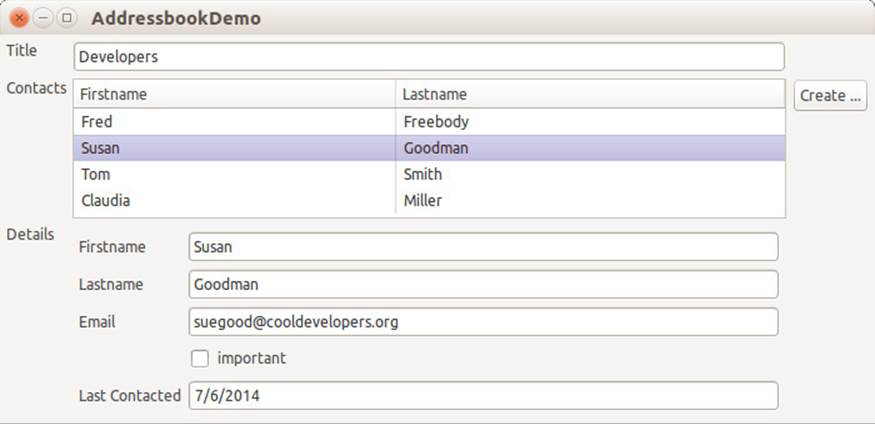
Figure 9.9 Address Book Editor
![]()
![]() 7.2.2The JFace data binding framework lives in several plugins, which must be set as dependencies in the MANIFEST.MF of any plugin using the framework. In the spirit of
7.2.2The JFace data binding framework lives in several plugins, which must be set as dependencies in the MANIFEST.MF of any plugin using the framework. In the spirit of![]() 9.1 model-view separation, those parts not dealing with the user interface reside inorg.eclipse.core.databinding, org.eclipse.core.databinding.beans, and org.eclipse.core.property. Those connected to the display directly reside in the plugin org.eclipse.jface.databinding.
9.1 model-view separation, those parts not dealing with the user interface reside inorg.eclipse.core.databinding, org.eclipse.core.databinding.beans, and org.eclipse.core.property. Those connected to the display directly reside in the plugin org.eclipse.jface.databinding.
9.3.3.1 Basics of Data Binding
The data binding framework is very general and is meant to cover many possible applications. Fig. 9.10 gives an overview of the elements involved in one binding. The endpoints, to the far left and right, are the widget and bean created by the application. The purpose of a binding is to synchronize the value of selected properties in the respective beans. Bindings are, in principle, symmetric: They transfer changes from one bean to the other, and vice versa. Nevertheless, the terminology distinguishes between a model and the target of a binding, where the target is usually a widget. The figure![]() 9.1 also indicates the role of data binding in the general scheme of model-view separation.
9.1 also indicates the role of data binding in the general scheme of model-view separation.
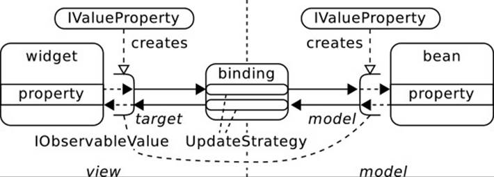
Figure 9.10 Overview of JFace Data Binding
To keep the data binding framework independent of the application![]() 2.4.1 objects, these are adapted to the IObservableValue interface in the next code snippet, as indicated by the half-open objects beside the properties in Fig. 9.10. The adapters enable getting and setting a value, as well as
2.4.1 objects, these are adapted to the IObservableValue interface in the next code snippet, as indicated by the half-open objects beside the properties in Fig. 9.10. The adapters enable getting and setting a value, as well as![]() 9.2.1 observing changes, as would be expected from the basic MVC pattern. The value type is used for consistency checking within the framework, as well as for accessing the adaptees efficiently by reflection.
9.2.1 observing changes, as would be expected from the basic MVC pattern. The value type is used for consistency checking within the framework, as well as for accessing the adaptees efficiently by reflection.
org.eclipse.core.databinding.observable.value.IObservableValue
public interface IObservableValue extends IObservable {
public Object getValueType();
public Object getValue();
public void setValue(Object value);
public void addValueChangeListener(
IValueChangeListener listener);
public void removeValueChangeListener(
IValueChangeListener listener);
}
The IObservableValue in this code captures values of atomic types. There are analogous interfaces IObservableList, IObservableSet, and IObservableMap to bind properties holding compound values.
Creating these adapters often involves some analysis, such as looking up the getter and setter methods for a named property by reflection. The adapters are therefore usually created by IValueProperty objects, which serve as abstract factories. Again, analogous interfacesIListProperty,![]() 1.4.12 ISetProperty, and IMapProperty capture factories for compound value properties.
1.4.12 ISetProperty, and IMapProperty capture factories for compound value properties.
org.eclipse.core.databinding.property.value.IValueProperty
public interface IValueProperty extends IProperty {
public Object getValueType();
public IObservableValue observe(Object source);
... observing parts of the value
}
We have now discussed enough of the framework to bind the name property of an AddressBook in the field model to a text field in the interface. Lines 1–2 in the next code snippet create an IValueProperty for the text property of an SWT widget and use it immediately to create the adapter for the bookname text field. The code specifies that the property is considered changed whenever the user leaves the field (event SWT.FocusOut); setting the event to SWT.Modify updates the model property after every keystroke. Lines 3–4 proceed analogously for the nameproperty of the AddressBook. Finally, lines 5–6 create the actual binding.
databinding.AddressBookDemo.initDataBindings
1 IObservableValue observeTextBooknameObserveWidget =
2 WidgetProperties .text(SWT.FocusOut).observe(bookname);
3 IObservableValue nameModelObserveValue =
4 BeanProperties.value("name") .observe(model);
5 bindingContext.bindValue(observeTextBooknameObserveWidget,
6 nameModelObserveValue, null, null);
![]() A binding context manages a set of bindings. The two null values in line 6 indicate that no update strategies (Fig. 9.10) are required.
A binding context manages a set of bindings. The two null values in line 6 indicate that no update strategies (Fig. 9.10) are required.
![]() The framework anticipates the possibility of multithreading in the model, which
The framework anticipates the possibility of multithreading in the model, which![]() 7.10.1 requires switching to the event dispatch thread at appropriate moments. Each observable value is said to live in a specific realm. One realm, accessible by SWTObservables. getRealm(), is associated with the event thread. A default realm can be set with Realm.runWithDefault(), so that it is usually not necessary to specify a realm explicitly for individual values.
7.10.1 requires switching to the event dispatch thread at appropriate moments. Each observable value is said to live in a specific realm. One realm, accessible by SWTObservables. getRealm(), is associated with the event thread. A default realm can be set with Realm.runWithDefault(), so that it is usually not necessary to specify a realm explicitly for individual values.
9.3.3.2 Master/Detail Views
Fig. 9.9 includes a typical editing scenario: The list contacts is a master list showing an overview; below this list, several fields give access to the details of the currently selected list element. The master list itself involves only binding a property, as seen in the following code snippet. On the viewer![]() 9.3.1 side, special content and label providers then accomplish the data access and updates.
9.3.1 side, special content and label providers then accomplish the data access and updates.
databinding.AddressBookDemo.initDataBindings
IObservableList contactsModelObserveList = BeanProperties
.list("contacts").observe(model);
contactsViewer.setInput(contactsModelObserveList);
The actual master/detail view is established by a two-step binding of properties. Lines 3–4 in the next example create a possibly changing value that tracks the currently selected Contact element as a value: Whenever the selection changes, the value of the property changes. Building on this, lines 5–8 create a two-step access path to the first name property: The observeDetail() call tracks the current Contact and registers as an observer for that contact, so that it also sees its property changes; the value() call then delivers an atomic String value for the property. Through these double observers, this atomic value will change whenever either the selection or the first name property of the current selection changes.
databinding.AddressBookDemo.initDataBindings
1 IObservableValue observeTextTxtFirstObserveWidget =
2 WidgetProperties.text(SWT.Modify).observe(txtFirst);
3 IObservableValue observeSingleSelectionContactsViewer =
4 ViewerProperties.singleSelection().observe(contactsViewer);
5 IObservableValue contactsViewerFirstnameObserveDetailValue =
6 BeanProperties
7 .value(Contact.class, "firstname", String.class)
8 .observeDetail(observeSingleSelectionContactsViewer);
9 bindingContext.bindValue(observeTextTxtFirstObserveWidget,
10 contactsViewerFirstnameObserveDetailValue, null, null);