OpenGL ES 3.0: Programming Guide, Second Edition (2014)
Chapter 8. Vertex Shaders
This chapter describes the OpenGL ES 3.0 programmable vertex pipeline. Figure 8-1 illustrates the entire OpenGL ES 3.0 programmable pipeline. The shaded boxes indicate the programmable stages in OpenGL ES 3.0. In this chapter, we discuss the vertex shader stage. Vertex shaders can be used to do traditional vertex-based operations such as transforming the position by a matrix, computing the lighting equation to generate a per-vertex color, and generating or transforming texture coordinates.
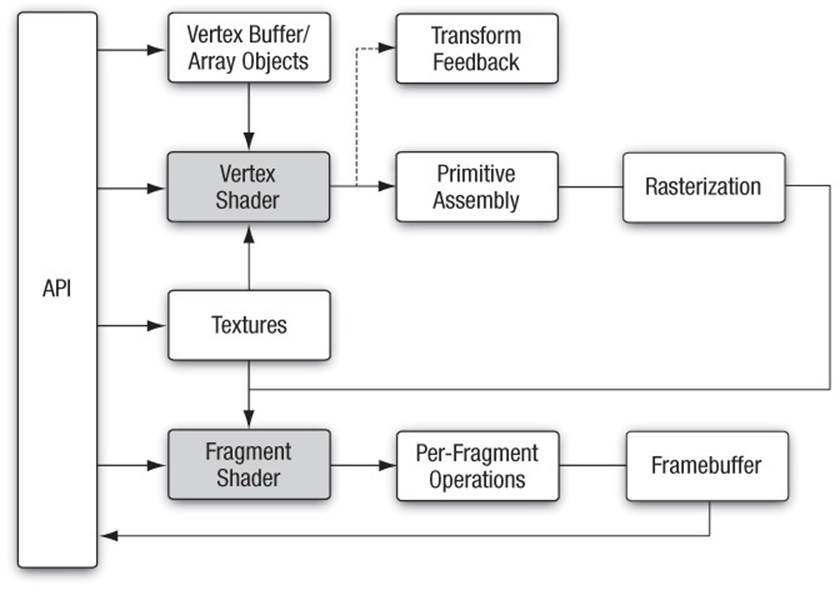
Figure 8-1 OpenGL ES 3.0 Programmable Pipeline
The previous chapters—specifically, Chapter 5, “OpenGL ES Shading Language,” and Chapter 6, “Vertex Attributes, Vertex Arrays, and Buffer Objects”—discussed how to specify the vertex attribute and uniform inputs and also gave a good description of the OpenGL ES 3.0 Shading Language. Chapter 7, “Primitive Assembly and Rasterization,” discussed how the output of the vertex shader, referred to as vertex shader output variables, is used by the rasterization stage to generate per-fragment values, which are then input to the fragment shader. In this chapter, we begin with a high-level overview of a vertex shader, including its inputs and outputs. We then describe how to write vertex shaders by discussing a few examples. These examples describe common use cases such as transforming a vertex position with a model view and projection matrix, vertex lighting that generates per-vertex diffuse and specular colors, texture coordinate generation, vertex skinning, and displacement mapping. We hope that these examples help you get a good idea of how to write vertex shaders. Last but not least, we describe a vertex shader that implements the OpenGL ES 1.1 fixed-function vertex pipeline.
Vertex Shader Overview
The vertex shader provides a general-purpose programmable method for operating on vertices. Figure 8-2 shows the inputs and outputs of a vertex shader. The inputs to the vertex shader consist of the following:
• Attributes—Per-vertex data supplied using vertex arrays.
• Uniforms and uniform buffers—Constant data used by the vertex shader.
• Samplers—A specific type of uniform that represents textures used by the vertex shader.
• Shader program—Vertex shader program source code or executable that describes the operations that will be performed on the vertex.
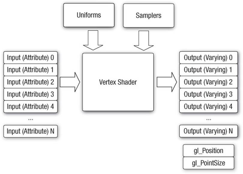
Figure 8-2 OpenGL ES 3.0 Vertex Shader
The outputs of the vertex shader are called vertex shader output variables. In the primitive rasterization stage, these variables are computed for each generated fragment and are passed in as inputs to the fragment shader.
Vertex Shader Built-In Variables
The built-in variables of a vertex shader can be categorized into special variables that are input or output of the vertex shader, uniform state such as depth range, and constants that specify maximum values such as the number of attributes, number of vertex shader output variables, and number of uniforms.
Built-In Special Variables
OpenGL ES 3.0 has built-in special variables that serve as inputs to the vertex shader, or outputs by the vertex shader that then become inputs to the fragment shader, or outputs by the fragment shader. The following built-in special variables are available to the vertex shader:
• gl_VertexID is an input variable that holds an integer index for the vertex. This integer variable is declared using the highp precision qualifier.
• gl_InstanceID is an input variable that holds the instance number of a primitive in an instanced draw call. Its value is 0 for a regular draw call. gl_InstanceID is an integer variable declared using the highp precision qualifier.
• gl_Position is used to output the vertex position in clip coordinates. Its values are used by the clipping and viewport stages to perform appropriate clipping of primitives and to convert the vertex position from clip coordinates to screen coordinates. The value of gl_Position is undefined if the vertex shader does not write to gl_Position. gl_Position is a floating-point variable declared using the highp precision qualifier.
• gl_PointSize is used to write the size of the point sprite in pixels. It is used when point sprites are rendered. The gl_PointSize value output by a vertex shader is then clamped to the aliased point size range supported by the OpenGL ES 3.0 implementation. gl_PointSizeis a floating-point variable declared using the highp precision qualifier.
• gl_FrontFacing is a special variable that, although not directly written by the vertex shader, is generated based on the position values generated by the vertex shader and primitive type being rendered. gl_FrontFacing is a boolean variable.
Built-In Uniform State
The only built-in uniform state available inside a vertex shader is the depth range in window coordinates. This is given by the built-in uniform name gl_DepthRange, which is declared as a uniform of type gl_DepthRangeParameters.
struct gl_DepthRangeParameters
{
highp float near; // near Z
highp float far; // far Z
highp float diff; // far – near
}
uniform gl_DepthRangeParameters gl_DepthRange;
Built-In Constants
The following built-in constants are also available inside the vertex shader:
const mediump int gl_MaxVertexAttribs = 16;
const mediump int gl_MaxVertexUniformVectors = 256;
const mediump int gl_MaxVertexOutputVectors = 16;
const mediump int gl_MaxVertexTextureImageUnits = 16;
const mediump int gl_MaxCombinedTextureImageUnits = 32;
The built-in constants describe the following maximum terms:
• gl_MaxVertexAttribs is the maximum number of vertex attributes that can be specified. The minimum value supported by all ES 3.0 implementations is 16.
• gl_MaxVertexUniformVectors is the maximum number of vec4 uniform entries that can be used inside a vertex shader. The minimum value supported by all ES 3.0 implementations is 256 vec4 entries. The number of vec4 uniform entries that can actually be used by a developer can vary from one implementation to another and from one vertex shader to another. For example, some implementations might count user-specified literal values used in a vertex shader against the uniform limit. In other cases, implementation-specific uniforms (or constants) might need to be included depending on whether the vertex shader makes use of any built-in transcendental functions. There currently is no mechanism that an application can use to find the number of uniform entries that it can use in a particular vertex shader. The vertex shader compilation will fail and the compile log might provide specific information with regard to number of uniform entries being used. However, the information returned by the compile log is implementation specific. We provide some guidelines in this chapter to help maximize the use of vertex uniform entries available in a vertex shader.
• gl_MaxVertexOutputVectors is the maximum number of output vectors—that is, the number of vec4 entries that can be output by a vertex shader. The minimum value supported by all ES 3.0 implementations is 16 vec4 entries.
• gl_MaxVertexTextureImageUnits is the maximum number of texture units available in a vertex shader. The minimum value is 16.
• gl_MaxCombinedTextureImageUnits is the sum of the maximum number of texture units available in the vertex + fragment shaders. The minimum value is 32.
The values specified for each built-in constant are the minimum values that must be supported by all OpenGL ES 3.0 implementations. It is possible that implementations might support values greater than the minimum values described. The actual supported values can be queried using the following code:
GLint maxVertexAttribs, maxVertexUniforms, maxVaryings;
GLint maxVertexTextureUnits, maxCombinedTextureUnits;
glGetIntegerv ( GL_MAX_VERTEX_ATTRIBS, &maxVertexAttribs );
glGetIntegerv ( GL_MAX_VERTEX_UNIFORM_VECTORS,
&maxVertexUniforms );
glGetIntegerv ( GL_MAX_VARYING_VECTORS,
&maxVaryings );
glGetIntegerv ( GL_MAX_VERTEX_TEXTURE_IMAGE_UNITS,
&maxVertexTextureUnits );
glGetIntegerv ( GL_MAX_COMBINED_TEXTURE_IMAGE_UNITS,
&maxCombinedTextureUnits );
Precision Qualifiers
This section briefly reviews precision qualifiers, which are covered in depth in Chapter 5, “OpenGL ES Shading Language.” Precision qualifiers can be used to specify the precision of any floating-point or integer-based variable. The keywords for specifying the precision are lowp,mediump, and highp. Some examples of declarations with precision qualifiers are shown here:
highp vec4 position;
out lowp vec4 color;
mediump float specularExp;
highp int oneConstant;
In addition to precision qualifiers, default precision may be employed. That is, if a variable is declared without having a precision qualifier, it will have the default precision for that type. The default precision qualifier is specified at the top of a vertex or fragment shader using the following syntax:
precision highp float;
precision mediump int;
The precision specified for float will be used as the default precision for all variables based on a floating-point value. Likewise, the precision specified for int will be used as the default precision for all integer-based variables. In the vertex shader, if no default precision is specified, the default precision for both int and float is highp.
For operations typically performed in a vertex shader, the precision qualifier that will most likely be needed is highp. For instance, operations that transform a position with a matrix, transform normals and texture coordinates, or generate texture coordinates will need to be done with highpprecision. Color computations and lighting equations can most likely be done with mediump precision. Again, this decision will depend on the kind of color computations being performed and the range and precision required for the operations being performed. We believe that highp will most likely be the default precision used for most operations in a vertex shader; thus we use highp as the default precision qualifier in the examples that follow.
Number of Uniforms Limitations in a Vertex Shader
gl_MaxVertexUniformVectors describes the maximum number of uniforms that can be used in a vertex shader. The minimum value for gl_MaxVertexUniformVectors that must be supported by any compliant OpenGL ES 3.0 implementation is 256 vec4 entries. The uniform storage is used to store the following variables:
• Variables declared with the uniform qualifier
• Constant variables
• Literal values
• Implementation-specific constants
The number of uniform variables used in a vertex shader along with the variables declared with the const qualifier, literal values, and implementation- specific constants must fit in gl_MaxVertexUniformVectors as per the packing rules described in Chapter 5, “OpenGL ES Shading Language.” If these do not fit, then the vertex shader will fail to compile. A developer might potentially apply the packing rules and determine the amount of uniform storage needed to store uniform variables, constant variables, and literal values. It is not possible to determine the number of implementation-specific constants, however, as this value will not only vary from implementation to implementation but will also change depending on which built-in shading language functions are being used by the vertex shader. Typically, the implementation-specific constants are required when built-in transcendental functions are used.
As far as literal values are concerned, the OpenGL ES 3.0 Shading Language specification states that no constant propagation is assumed. As a consequence, multiple instances of the same literal value(s) will be counted multiple times. Understandably, it is easier to use literal values such as0.0 or 1.0 in a vertex shader, but our recommendation is that this technique be avoided as much as possible. Instead of using literal values, appropriate constant variables should be declared. This approach avoids having to perform the same literal value count multiple times, which might cause the vertex shader to fail to compile if vertex uniform storage requirements exceed what the implementation supports.
Consider the following example, which shows a snippet of vertex shader code that transforms two texture coordinates per vertex:
#version 300 es
#define NUM_TEXTURES 2
uniform mat4 tex_matrix[NUM_TEXTURES]; // texture
// matrices
uniform bool enable_tex[NUM_TEXTURES]; // texture
// enables
uniform bool enable_tex_matrix[NUM_TEXTURES]; // texture matrix
// enables
in vec4 a_texcoord0; // available if enable_tex[0] is true
in vec4 a_texcoordl; // available if enable_tex[1] is true
out vec4 v_texcoord[NUM_TEXTURES];
void main()
{
v_texcoord[0] = vec4 ( 0.0, 0.0, 0.0, 1.0 );
// is texture 0 enabled
if ( enable_tex[0] )
{
// is texture matrix 0 enabled
if ( enable_tex_matrix[0] )
v_texcoord[0] = tex_matrix[0] * a_texcoord0;
else
v_texcoord[0] = a_texcoord0;
}
v_texcoord[1] = vec4 ( 0.0, 0.0, 0.0, 1.0 );
// is texture 1 enabled
if ( enable_tex[1] )
{
// is texture matrix 1 enabled
if ( enable_tex_matrix[1] )
v_texcoord[1] = tex_matrix[1] * a_texcoordl;
else
v_texcoord[1] = a_texcoordl;
}
// set gl_Position to make this into a valid vertex shader
}
This code might result in each reference to the literal values 0, 1, 0.0, and 1.0 counting against the uniform storage. To guarantee that these literal values count only once against the uniform storage, the vertex shader code snippet should be written as follows:
#version 300 es
#define NUM_TEXTURES 2
const int c_zero = 0;
const int c_one = 1;
uniform mat4 tex_matrix[NUM_TEXTURES]; // texture
// matrices
uniform bool enable_tex[NUM_TEXTURES]; // texture
// enables
uniform bool enable_tex_matrix[NUM_TEXTURES]; // texture matrix
// enables
in vec4 a_texcoord0; // available if enable_tex[0] is true
in vec4 a_texcoordl; // available if enable_tex[1] is true
out vec4 v_texcoord[NUM_TEXTURES];
void main()
{
v_texcoord[c_zero] = vec4 ( float(c_zero), float(c_zero),
float(c_zero), float(c_one) );
// is texture 0 enabled
if ( enable_tex[c_zero] )
{
// is texture matrix 0 enabled
if ( enable_tex_matrix[c_zero] )
v_texcoord[c_zero] = tex_matrix[c_zero] * a_texcoord0;
else
v_texcoord[c_zero] = a_texcoord0;
}
v_texcoord[c_one] = vec4(float(c_zero), float(c_zero),
float(c_zero), float(c_one));
// is texture 1 enabled
if ( enable_tex[c_one] )
{
// is texture matrix 1 enabled
if ( enable_tex_matrix[c_one] )
v_texcoord[c_one] = tex_matrix[c_one] * a_texcoordl;
else
v_texcoord[c_one] = a_texcoordl;
}
// set gl_Position to make this into a valid vertex shader
}
This section should help you better understand the limitations of the OpenGL ES 3.0 Shading Language and appreciate how to write vertex shaders that should compile and run on most OpenGL ES 3.0 implementations.
Vertex Shader Examples
We now present a few examples that demonstrate how to implement the following features in a vertex shader:
• Transforming vertex position with a matrix
• Lighting computations to generate per-vertex diffuse and specular color
• Texture coordinate generation
• Vertex skinning
• Displacing vertex position with a texture lookup value
These features represent typical use cases that OpenGL ES 3.0 applications will want to perform in a vertex shader.
Matrix Transformations
Example 8-1 describes a simple vertex shader written using the OpenGL ES Shading Language. The vertex shader takes a position and its associated color data as inputs or attributes, transforms the position by a 4 × 4 matrix, and outputs the transformed position and color.
Example 8-1 Vertex Shader with Matrix Transform for the Position
#version 300 es
// uniforms used by the vertex shader
uniform mat4 u_mvpMatrix; // matrix to convert position from
// model space to clip space
// attribute inputs to the vertex shader
layout(location = 0) in vec4 a_position; // input position value
layout(location = 1) in vec4 a_color; // input color
// vertex shader output, input to the fragment shader
out vec4 v_color;
void main()
{
v_color = a_color;
gl_Position = u_mvpMatrix * a_position;
}
The transformed vertex positions and primitive type are then used by the setup and rasterization stages to rasterize the primitive into fragments. For each fragment, the interpolated v_color will be computed and passed as input to the fragment shader.
Example 8-1 introduces the concept of the model–view–projection (MVP) matrix in the uniform u_mvpMatrix. As described in the Coordinate Systems section in Chapter 7, the positions input to the vertex shader are stored in object coordinates and the output position of the vertex shader is stored in clip coordinates. The MVP matrix is the product of three very important transformation matrices in 3D graphics that perform this transformation: the model matrix, the view matrix, and the projection matrix.
The transformations performed by each of the individual matrices that make up the MVP matrix are as follows:
• Model matrix—Transform object coordinates to world coordinates.
• View matrix—Transform world coordinates to eye coordinates.
• Projection matrix—Transform eye coordinates to clip coordinates.
Model–View Matrix
In traditional fixed-function OpenGL, the model and view matrices are combined into a single matrix known as the model–view matrix. This 4 × 4 matrix transforms the vertex position from object coordinates into eye coordinates. It is the combination of the transformation from object to world coordinates and the transformation from world to eye coordinates. In fixed-function OpenGL, the model–view matrix can be created using functions such as glRotatef, glTranslatef, and glScalef. Because these functions do not exist in OpenGL ES 2.0 or 3.0, it is up to the application to handle creation of the model–view matrix.
To simply this process, we have included in the sample code framework esTransform.c, which contains functions that perform equivalently to the fixed-function OpenGL routines for building a model–view matrix. These transformation functions (esRotate, esTranslate,esScale, esMatrixLoadIdentity, and esMatrixMultiply) are detailed in Appendix C. In Example 8-1, the model–view matrix is computed as follows:
ESMatrix modelview;
// Generate a model-view matrix to rotate/translate the cube
esMatrixLoadIdentity ( &modelview );
// Translate away from the viewer
esTranslate ( &modelview, 0.0, 0.0, -2.0 );
// Rotate the cube
esRotate ( &modelview, userData->angle, 1.0, 0.0, 1.0 );
First, the identity matrix is loaded into the modelview matrix using esMatrixLoadIdentity. Then the identity matrix is concatenated with a translation that moves the object away from the viewer. Finally, a rotation is concatenated to the modelview matrix that rotates the object around the vector (1.0, 0.0, 1.0) with an angle in degrees that is updated based on time to rotate the object continuously.
Projection Matrix
The projection matrix takes the eye coordinates (computed from applying the model–view matrix) and produces clip coordinates as described in the Clipping section in Chapter 7. In fixed-function OpenGL, this transformation was specified using glFrustum or the OpenGL utility functiongluPerspective. In the OpenGL ES Framework API, we have provided two equivalent functions: esFrustum and esPerspective. These functions specify the clip volume detailed in Chapter 7. The esFrustum function describes the clip volume by specifying the coordinates of the clip volume. The esPerspective function is a convenience function that computes the parameters to esFrustum using a field-of-view and aspect ratio description of the viewing volume. The projection matrix is computed for Example 8-1 as follows:
ESMatrix projection;
// Compute the window aspect ratio
aspect = (GLfloat) esContext->width /
(GLfloat) esContext->height;
// Generate a perspective matrix with a 60-degree FOV
// and near and far clip planes at 1.0 and 20.0
esMatrixLoadIdentity ( &projection);
esPerspective ( &projection, 60.0f, aspect, 1.0f, 20.0f );
Finally, the MVP matrix is computed as the product of the model–view and projection matrices:
// Compute the final MVP by multiplying the
// model-view and projection matrices together
esMatrixMultiply ( &userData->mvpMatrix, &modelview,
&projection );
The MVP matrix is loaded into the uniform for the shader using glUniformMatrix4fv.
// Get the uniform locations
userData->mvpLoc =
glGetUniformLocation ( userData->programObject,
"u_mvpMatrix" );
...
// Load the MVP matrix
glUniformMatrix4fv( userData->mvpLoc, 1, GL_FALSE,
(GLfloat*) &userData->mvpMatrix.m[0][0] );
Lighting in a Vertex Shader
In this section, we look at examples that compute the lighting equation for directional lights, point lights, and spotlights. The vertex shaders described in this section use the OpenGL ES 1.1 lighting equation model to compute the lighting equation for a directional or a spot (or point) light. In the lighting examples described here, the viewer is assumed to be at infinity.
A directional light is a light source that is at an infinite distance from the objects in the scene being lit. An example of a directional light is the sun. As the light is at infinite distance, the light rays from the light source are parallel. The light direction vector is a constant and does not need to be computed per vertex. Figure 8-3 describes the terms that are needed in computing the lighting equation for a directional light. Peye is the position of the viewer, Plight is the position of the light (Plight . w = 0), N is the normal, and H is the half-plane vector. Because Plight . w = 0, the light direction vector will be Plight . xyz. The half-plane vector H is computed as ||VPlight + VPeye||. As both the light source and viewer are at infinity, the half-plane vector H = ||Plight . xyz + (0, 0, l)||.
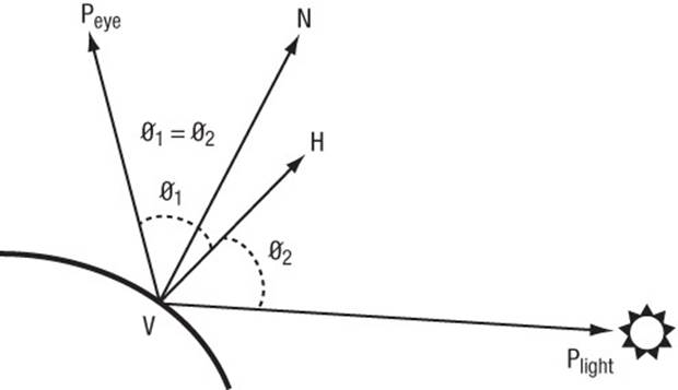
Figure 8-3 Geometric Factors in Computing Lighting Equation for a Directional Light
Example 8-2 provides the vertex shader code that computes the lighting equation for a directional light. The directional light properties are described by a directional_light struct that contains the following elements:
• direction—The normalized light direction in eye space.
• halfplane—The normalized half-plane vector H. This can be precomputed for a directional light, as it does not change.
• ambient_color—The ambient color of the light.
• diffuse_color—The diffuse color of the light.
• specular_color—The specular color of the light.
The material properties needed to compute the vertex diffuse and specular color are described by a material_properties struct that contains the following elements:
• ambient_color—The ambient color of the material.
• diffuse_color—The diffuse color of the material.
• specular_color—The specular color of the material.
• specular_exponent—The specular exponent that describes the shininess of the material and is used to control the shininess of the specular highlight.
Example 8-2 Directional Light
#version 300 es
struct directional_light
{
vec3 direction; // normalized light direction in eye
// space
vec3 halfplane; // normalized half-plane vector
vec4 ambient_color;
vec4 diffuse_color;
vec4 specular_color;
};
struct material_properties
{
vec4 ambient_color;
vec4 diffuse_color;
vec4 specular_color;
float specular_exponent;
};
const float c_zero = 0.0;
const float c_one = 1.0;
uniform material_properties material;
uniform directional_light light;
// normal has been transformed into eye space and is a
// normalized vector; this function returns the computed color
vec4 directional_light_color ( vec3 normal )
{
vec4 computed_color = vec4 ( c_zero, c_zero, c_zero,
c_zero );
float ndotl; // dot product of normal & light direction
float ndoth; // dot product of normal & half-plane vector
ndotl = max ( c_zero, dot ( normal, light.direction ) );
ndoth = max ( c_zero, dot ( normal, light.halfplane ) );
computed_color += ( light.ambient_color
* material.ambient_color );
computed_color += ( ndotl * light.diffuse_color
* material.diffuse_color );
if ( ndoth > c_zero )
{
computed_color += ( pow ( ndoth,
material.specular_exponent )*
material.specular_color *
light.specular_color );
}
return computed_color;
}
// add a main function to make this into a valid vertex shader
The directional light vertex shader code described in Example 8-2 combines the per-vertex diffuse and specular color into a single color (given by computed_color). Another option would be to compute the per-vertex diffuse and specular colors and pass them as separate output variables to the fragment shader.
Note
In Example 8-2, we multiply the material colors (ambient, diffuse, and specular) with the light colors. This is fine if we are computing the lighting equation for only one light. If we have to compute the lighting equation for multiple lights, however, we should compute the ambient, diffuse, and specular values for each light and then compute the final vertex color by multiplying the material ambient, diffuse, and specular colors with appropriate computed terms and then summing them to generate a per-vertex color.
A point light is a light source that emanates light in all directions from a position in space. A point light is given by a position vector (x, y, z, w), where w ≠ 0. The point light shines evenly in all directions but its intensity falls off (i.e., becomes attenuated) based on the distance from the light to the object. This attenuation is computed using the following equation:
distance attenuation = 1/(K0 + K1 × || VPlight || + K2 × || VPlight||2)
where K0, K1, and K2 are the constant, linear, and quadratic attenuation factors, respectively.
A spotlight is a light source with both a position and a direction that simulates a cone of light emitted from a position (Plight) in a direction (given by spotdirection). Figure 8-4 describes the terms that are needed in computing the lighting equation for a spotlight.
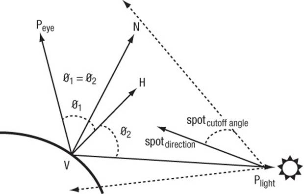
Figure 8-4 Geometric Factors in Computing Lighting Equation for a Spotlight
The intensity of the emitted light is attenuated by a spot cutoff factor based on the angle from the center of the cone. The angle away from the center axis of the cone is computed as the dot product of VPlight and spotdirection. The spot cutoff factor is 1.0 in the spotlight direction given byspotdirection and falls off exponentially to 0.0 at spotcutoff angle radians away.
Example 8-3 describes the vertex shader code that computes the lighting equation for a spot (and point) light. The spotlight properties are described by a spot_light struct that contains the following elements:
• direction—The light direction in eye space.
• ambient_color—The ambient color of the light.
• diffuse_color—The diffuse color of the light.
• specular_color—The specular color of the light.
• attenuation_factors—The distance attenuation factors K0, K1, and K2.
• compute_distance_attenuation—A boolean term that determines whether the distance attenuation must be computed.
• spot_direction—The normalized spot direction vector.
• spot_exponent—The spotlight exponent used to compute the spot cutoff factor.
• spot_cutoff_angle—The spotlight cutoff angle in degrees.
Example 8-3 Spotlight
#version 300 es
struct spot_light
{
vec4 position; // light position in eye space
vec4 ambient_color;
vec4 diffuse_color;
vec4 specular_color;
vec3 spot_direction; // normalized spot direction
vec3 attenuation_factors; // attenuation factors K0, K1, K2
bool compute_distance_attenuation;
float spot_exponent; // spotlight exponent term
float spot_cutoff_angle; // spot cutoff angle in degrees
};
struct material_properties
{
vec4 ambient_color;
vec4 diffuse_color;
vec4 specular_color;
float specular_exponent;
};
const float c_zero = 0.0;
const float c_one = 1.0;
uniform material_properties material;
uniform spot_light light;
// normal and position are normal and position values in
// eye space.
// normal is a normalized vector.
// This function returns the computed color.
vec4 spot_light_color ( vec3 normal, vec4 position )
{
vec4 computed_color = vec4 ( c_zero, c_zero, c_zero,
c_zero );
vec3 lightdir;
vec3 halfplane;
float ndotl, ndoth;
float att_factor;
att_factor = c_one;
// we assume "w" values for light position and
// vertex position are the same
lightdir = light.position.xyz - position.xyz;
// compute distance attenuation
if ( light.compute_distance_attenuation )
{
vec3 att_dist;
att_dist.x = c_one;
att_dist.z = dot ( lightdir, lightdir );
att_dist.y = sqrt ( att_dist.z );
att_factor = c_one / dot ( att_dist,
light.attenuation_factors );
}
// normalize the light direction vector
lightdir = normalize ( lightdir );
// compute spot cutoff factor
if ( light.spot_cutoff_angle < 180.0 )
{
float spot_factor = dot ( -lightdir,
light.spot_direction );
if ( spot_factor >= cos ( radians (
light.spot_cutoff_angle ) ) )
spot_factor = pow ( spot_factor, light.spot_exponent );
else
spot_factor = c_zero;
// compute combined distance and spot attenuation factor
att_factor *= spot_factor;
}
if ( att_factor > c_zero )
{
// process lighting equation --> compute the light color
computed_color += ( light.ambient_color *
material.ambient_color );
ndotl = max ( c_zero, dot(normal, lightdir ) );
computed_color += ( ndotl * light.diffuse_color *
material.diffuse_color );
halfplane = normalize ( lightdir + vec3 ( c_zero, c_zero,
c_one ) );
ndoth = dot ( normal, halfplane );
if ( ndoth > c_zero )
{
computed_color += ( pow ( ndoth,
material.specular_exponent )*
material.specular_color *
light.specular_color );
}
// multiply color with computed attenuation
computed_color *= att_factor;
}
return computed_color;
}
// add a main function to make this into a valid vertex shader
Generating Texture Coordinates
We look at two examples that generate texture coordinates in a vertex shader. The two examples are used when rendering shiny (i.e., reflective) objects in a scene by generating a reflection vector and then using this vector to compute a texture coordinate that indexes into a latitude–longitude map (also called a sphere map) or a cubemap (represents six views or faces that capture reflected environment, assuming a single viewpoint in the middle of the shiny object). The fixed-function OpenGL specification describes the texture coordinate generation modes as GL_SPHERE_MAPand GL_REFLECTION_MAP, respectively. The GL_SPHERE_MAP mode generates a texture coordinate that uses a reflection vector to compute a 2D texture coordinate for lookup into a 2D texture map. The GL_REFLECTION_MAP mode generates a texture coordinate that is a reflection vector, which can then can be used as a 3D texture coordinate for lookup into a cubemap. Examples 8-4 and 8-5 show the vertex shader code that generates the texture coordinates that will be used by the appropriate fragment shader to calculate the reflected image on the shiny object.
Example 8-4 Sphere Map Texture Coordinate Generation
// position is the normalized position coordinate in eye space.
// normal is the normalized normal coordinate in eye space.
// This function returns a vec2 texture coordinate.
vec2 sphere_map ( vec3 position, vec3 normal )
{
reflection = reflect ( position, normal );
m = 2.0 * sqrt ( reflection.x * reflection.x +
reflection.y * reflection.y +
( reflection.z + 1.0 ) * ( reflection.z + 1.0 ) );
return vec2(( reflection.x / m + 0.5 ),
( reflection.y / m + 0.5 ) );
}
Example 8-5 Cubemap Texture Coordinate Generation
// position is the normalized position coordinate in eye space.
// normal is the normalized normal coordinate in eye space.
// This function returns the reflection vector as a vec3 texture
// coordinate.
vec3 cube_map ( vec3 position, vec3 normal )
{
return reflect ( position, normal );
}
The reflection vector will then be used inside a fragment shader as the texture coordinate to the appropriate cubemap.
Vertex Skinning
Vertex skinning is a commonly used technique whereby the joins between polygons are smoothed. This is implemented by applying additional transform matrices with appropriate weights to each vertex. The multiple matrices used to skin vertices are stored in a matrix palette. The matrices’ indices per vertex are used to refer to appropriate matrices in the matrix palette that will be used to skin the vertex. Vertex skinning is commonly used for character models in 3D games to ensure that they appear smooth and realistic (as much as possible) without having to use additional geometry. The number of matrices used to skin a vertex is typically two to four.
The mathematics of vertex skinning is given by the following equations:
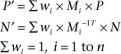
where
n is the number of matrices that will be used to transform the vertex
P is the vertex position
P' is the transformed (skinned) position
N is the vertex normal
N' is the transformed (skinned) normal
Mi is the matrix associated with the ith matrix per vertex and is computed as
Mi = matrix_palette [ matrix_index[i] ]
with n matrix_index values specified per vertex
Mi–1T is the inverse transpose of matrix Mi
Wi is the weight associated with the matrix
We discuss how to implement vertex skinning with a matrix palette of 32 matrices and up to four matrices per vertex to generate a skinned vertex. A matrix palette size of 32 matrices is quite common. The matrices in the matrix palette typically are 4 × 3 column major matrices (i.e., fourvec3 entries per matrix). If the matrices were to be stored in column-major order, 128 uniform entries with 3 elements of each uniform entry would be necessary to store a row. The minimum value of gl_MaxVertexUniformVectors that is supported by all OpenGL ES 3.0 implementations is 256 vec4 entries. Thus we will have only the fourth row of these 256 vec4 uniform entries available. This row of floating-point values can store only uniforms declared to be of type float (as per the uniform packing rule). There is no room, therefore, to store a vec2,vec3, or vec4 uniform. It would be better to store the matrices in the palette in row-major order using three vec4 entries per matrix. If we did this, then we would use 96 vec4 entries of uniform storage and the remaining 160 vec4 entries could be used to store other uniforms. Note that we do not have enough uniform storage to store the inverse transpose matrices needed to compute the skinned normal. This is typically not a problem, however: In most cases, the matrices used are orthonormal and, therefore, can be used to transform the vertex position and the normal.
Example 8-6 shows the vertex shader code that computes the skinned normal and position. We assume that the matrix palette contains 32 matrices, and that these matrices are stored in row-major order. The matrices are also assumed to be orthonormal (i.e., the same matrix can be used to transform position and normal) and up to four matrices are used to transform each vertex.
Example 8-6 Vertex Skinning Shader with No Check of Whether Matrix Weight = 0
#version 300 es
#define NUM_MATRICES 32 // 32 matrices in matrix palette
const int c_zero = 0;
const int c_one = 1;
const int c_two = 2;
const int c_three = 3;
// store 32 4 x 3 matrices as an array of floats representing
// each matrix in row-major order (i.e., 3 vec4s)
uniform vec4 matrix_palette[NUM_MATRICES * 3];
// vertex position and normal attributes
in vec4 a_position;
in vec3 a_normal;
// matrix weights - 4 entries / vertex
in vec4 a_matrixweights;
// matrix palette indices
in vec4 a_matrixindices;
void skin_position ( in vec4 position, float m_wt, int m_indx,
out vec4 skinned_position )
{
vec4 tmp;
tmp.x = dot ( position, matrix_palette[m_indx] );
tmp.y = dot ( position, matrix_palette[m_indx + c_one] );
tmp.z = dot ( position, matrix_palette[m_indx + c_two] );
tmp.w = position.w;
skinned_position += m_wt * tmp;
}
void skin_normal ( in vec3 normal, float m_wt, int m_indx,
inout vec3 skinned_normal )
{
vec3 tmp;
tmp.x = dot ( normal, matrix_palette[m_indx].xyz );
tmp.y = dot ( normal, matrix_palette[m_indx + c_one].xyz );
tmp.z = dot ( normal, matrix_palette[m_indx + c_two].xyz );
skinned_normal += m_wt * tmp;
}
void do_skinning ( in vec4 position, in vec3 normal,
out vec4 skinned_position,
out vec3 skinned_normal )
{
skinned_position = vec4 ( float ( c_zero ) );
skinned_normal = vec3 ( float ( c_zero ) );
// transform position and normal to eye space using matrix
// palette with four matrices used to transform a vertex
float m_wt = a_matrixweights[0];
int m_indx = int ( a_matrixindices[0] ) * c_three;
skin_position ( position, m_wt, m_indx, skinned_position );
skin_normal ( normal, m_wt, m_indx, skinned_normal );
m_wt = a_matrixweights[1] ;
m_indx = int ( a_matrixindices[1] ) * c_three;
skin_position ( position, m_wt, m_indx, skinned_position );
skin_normal ( normal, m_wt, m_indx, skinned_normal );
m_wt = a_matrixweights[2];
m_indx = int ( a_matrixindices[2] ) * c_three;
skin_position ( position, m_wt, m_indx, skinned_position );
skin_normal ( normal, m_wt, m_indx, skinned_normal );
m_wt = a_matrixweights[3];
m_indx = int ( a_matrixindices[3] ) * c_three;
skin_position ( position, m_wt, m_indx, skinned_position );
skin_normal ( normal, m_wt, m_indx, skinned_normal );
}
// add a main function to make this into a valid vertex shader
In Example 8-6, the vertex skinning shader generates a skinned vertex by transforming a vertex with four matrices and appropriate matrix weights. It is possible and quite common that some of these matrix weights may be zero. In Example 8-6, the vertex is transformed using all four matrices, irrespective of their weights. It might be better, however, to use a conditional expression to check whether the matrix weight is zero before calling skin_position and skin_normal. In Example 8-7, the vertex skinning shader checks for a matrix weight of zero before applying the matrix transformation.
Example 8-7 Vertex Skinning Shader with Checks of Whether Matrix Weight = 0
void do_skinning ( in vec4 position, in vec3 normal,
out vec4 skinned_position,
out vec3 skinned_normal )
{
skinned_position = vec4 ( float ( c_zero ) );
skinned_normal = vec3 ( float( c_zero ) );
// transform position and normal to eye space using matrix
// palette with four matrices used to transform a vertex
int m_indx = 0;
float m_wt = a_matrixweights[0];
if ( m_wt > 0.0 )
{
m_indx = int ( a_matrixindices[0] ) * c_three;
skin_position( position, m_wt, m_indx, skinned_position );
skin_normal ( normal, m_wt, m_indx, skinned_normal );
}
m_wt = a_matrixweights[1] ;
if ( m_wt > 0.0 )
{
m_indx = int ( a_matrixindices[1] ) * c_three;
skin_position( position, m_wt, m_indx, skinned_position );
skin_normal ( normal, m_wt, m_indx, skinned_normal );
}
m_wt = a_matrixweights[2] ;
if ( m_wt > 0.0 )
{
m_indx = int ( a_matrixindices[2] ) * c_three;
skin_position( position, m_wt, m_indx, skinned_position );
skin_normal ( normal, m_wt, m_indx, skinned_normal );
}
m_wt = a_matrixweights[3];
if ( m_wt > 0.0 )
{
m_indx = int ( a_matrixindices[3] ) * c_three;
skin_position( position, m_wt, m_indx, skinned_position );
skin_normal ( normal, m_wt, m_indx, skinned_normal );
}
}
At first glance, we might conclude that the vertex skinning shader in Example 8-7 offers better performance than the vertex skinning shader in Example 8-6. This is not necessarily true; indeed, the answer can vary across GPUs. Such variations occur because in the conditional expression if (m_wt > 0.0), m_wt is a dynamic value and can be different for vertices being executed in parallel by the GPU. We now run into divergent flow control where vertices being executed in parallel may have different values for m_wt, which in turn can cause execution to serialize. If a GPU does not implement divergent flow control efficiently, the vertex shader in Example 8-7 might not be as efficient as the version in Example 8-6. Applications should, therefore, test performance of divergent flow control by executing a test shader on the GPU as part of the application initialization phase to determine which shaders to use.
Transform Feedback
The transform feedback mode allows for capturing the outputs of the vertex shader into buffer objects. The output buffers then can be used as sources of the vertex data in a subsequent draw call. This approach is useful for a wide range of techniques that perform animation on the GPU without any CPU intervention, such as particle animation or physics simulation using render-to-vertex-buffer.
To specify the set of vertex attributes to be captured during the transform feedback mode, use the following command:
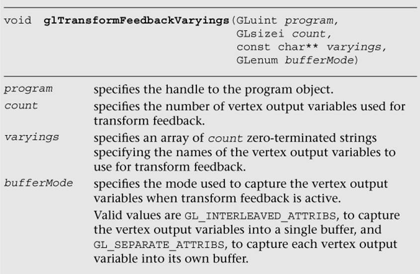
After calling glTransformFeedbackVaryings, it is necessary to link the program object using glLinkProgram. For example, to specify two vertex attributes to be captured into one transform feedback buffer, the code will be as follows:
const char* varyings[] = { "v_position", "v_color" };
glTransformFeedbackVarying ( programObject, 2, varyings,
GL_INTERLEAVED_ATTRIBS );
glLinkProgram ( programObject );
Then, we need to bind one or more buffer objects as the transform feedback buffers using glBindBuffer with GL_TRANSFORM_FEEDBACK_BUFFER. The buffer is allocated using glBufferData with GL_TRANSFORM_FEEDBACK_BUFFER and bound to the indexed binding points using glBindBufferBase or glBindBufferRange. These buffer APIs are described in more details in Chapter 6, “Vertex Attributes, Vertex Arrays, and Buffer Objects.”
After the transform feedback buffers are bound, we can enter and exit the transform feedback mode using the following API calls:
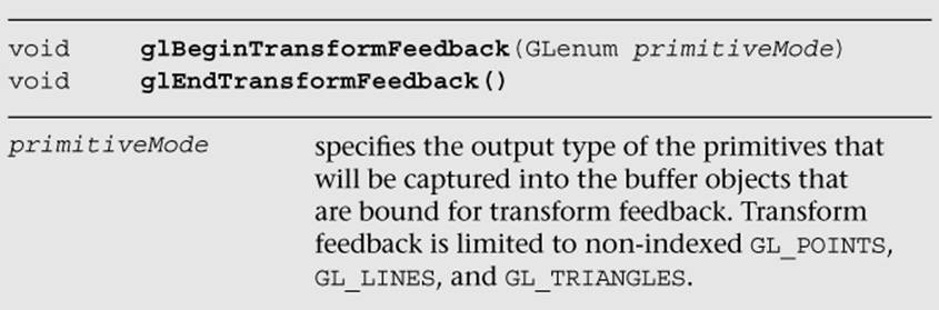
All draw calls that occur between glBeginTransformFeedback and glEndTransformFeedback will have their vertex outputs captured into the transform feedback buffers. Table 8-1 indicates the allowed draw mode corresponding to the transform feedback primitive mode.
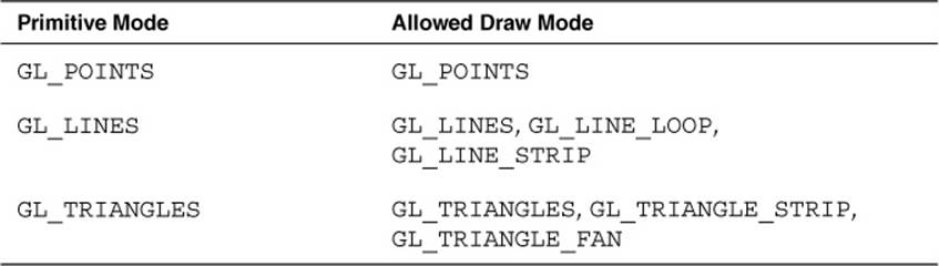
Table 8-1 Transform Feedback Primitive Mode and Allowed Draw Mode
We can retrieve the number of primitives that were successfully written into the transform buffer objects using glGetQueryObjectuiv after setting up glBeginQuery and glEndQuery with GL_TRANSFORM_FEEDBACK_PRIMITIVES_WRITTEN. For example, to begin and end the transform feedback mode for rendering a set of points and querying the number of points written, the code will be as follows:
glBeginTransformFeedback ( GL_POINTS );
glBeginQuery ( GL_TRANSFORM_FEEDBACK_PRIMITIVES_WRITTEN,
queryObject );
glDrawArrays ( GL_POINTS, 0, 10 );
glEndQuery ( GL_TRANSFORM_FEEDBACK_PRIMITIVES_WRITTEN );
glEndTransformFeedback ( );
// query the number of primitives written
glGetQueryObjectuiv( queryObject, GL_QUERY_RESULT,
&numPoints );
We can disable and enable rasterization while capturing in transform feedback mode using glEnable and glDisable with GL_RASTERIZER_DISCARD. While GL_RASTERIZER_DISCARD is enabled, no fragment shader will run.
Note that we describe a full example of using transform feedback in the Particle System Using Transform Feedback example in Chapter 14, “Advanced Programming with OpenGL ES 3.0.”
Vertex Textures
OpenGL ES 3.0 supports texture lookup operations in a vertex shader. This is useful to implement techniques such as displacement mapping, where you can displace the vertex position along the vertex normal based on the texture lookup value in the vertex shader. A typical application of the displacement mapping technique is for rendering terrain or water surfaces.
Performing texture lookup in a vertex shader has some notable limitations:
• The level of detail is not implicitly computed.
• The bias parameter in the texture lookup function is not accepted.
• The base texture is used for mipmapped texture.
The maximum number of texture image units supported by an implementation can be queried using glGetIntegerv with GL_MAX_VERTEX_TEXTURE_UNITS. The minimum number that an OpenGL ES 3.0 implementation can support is 16.
Example 8-8 is a sample vertex shader that performs displacement mapping. The process of loading textures on various texture units is described in more detail in Chapter 9, “Texturing.”
Example 8-8 Displacement Mapping Vertex Shader
#version 300 es
// uniforms used by the vertex shader
uniform mat4 u_mvpMatrix; // matrix to convert P from
// model space to clip space
uniform sampler2D displacementMap;
// attribute inputs to the vertex shader
layout(location = 0) in vec4 a_position; // input position value
layout(location = 1) in vec3 a_normal; // input normal value
layout(location = 2) in vec2 a_texcoord; // input texcoord value
layout(location = 3) in vec4 a_color; // input color
// vertex shader output, input to the fragment shader
out vec4 v_color;
void main ( )
{
v_color = a_color;
float displacement = texture ( displacementMap,
a_texcoord ).a;
vec4 displaced_position = a_position +
vec4 ( a_normal * displacement, 0.0 );
gl_Position = u_mvpMatrix * displaced_position;
}
We hope that the examples discussed so far have provided a good understanding of vertex shaders, including how to write them and how to use them for a wide-ranging array of effects.
OpenGL ES 1.1 Vertex Pipeline as an ES 3.0 Vertex Shader
We now discuss a vertex shader that implements the OpenGL ES 1.1 fixed-function vertex pipeline without vertex skinning. This is also meant to be an interesting exercise in figuring out how big a vertex shader can be and still run across all OpenGL ES 3.0 implementations.
This vertex shader implements the following fixed functions of the OpenGL ES 1.1 vertex pipeline:
• Transform the normal and position to eye space, if required (typically required for lighting). Rescale or normalization of normal is also performed.
• Compute the OpenGL ES 1.1 vertex lighting equation for up to eight directional lights, point lights, or spotlights with two-sided lighting and color material per vertex.
• Transform the texture coordinates for up to two texture coordinates per vertex.
• Compute the fog factor passed to the fragment shader. The fragment shader uses the fog factor to interpolate between fog color and vertex color.
• Compute the per-vertex user clip plane factor. Only one user clip plane is supported.
• Transform the position to clip space.
Example 8-9 is the vertex shader that implements the OpenGL ES 1.1 fixed-function vertex pipeline as already described.
Example 8-9 OpenGL ES 1.1 Fixed-Function Vertex Pipeline
#version 300 es
//**************************************************************
//
// OpenGL ES 3.0 vertex shader that implements the following
// OpenGL ES 1.1 fixed-function pipeline
//
// - compute lighting equation for up to eight
// directional/point/spotlights
// - transform position to clip coordinates
// - texture coordinate transforms for up to two texture
// coordinates
// - compute fog factor
// - compute user clip plane dot product (stored as
// v_ucp_factor)
//
//**************************************************************
#define NUM_TEXTURES 2
#define GLI_FOG_MODE_LINEAR 0
#define GLI_FOG_MODE_EXP 1
#define GLI_FOG_MODE_EXP2 2
struct light
{
vec4 position; // light position for a point/spotlight or
// normalized dir. for a directional light
vec4 ambient_color;
vec4 diffuse_color;
vec4 specular_color;
vec3 spot_direction;
vec3 attenuation_factors;
float spot_exponent;
float spot_cutoff_angle;
bool compute_distance_attenuation;
};
struct material
{
vec4 ambient_color;
vec4 diffuse_color;
vec4 specular_color;
vec4 emissive_color;
float specular_exponent;
};
const float c_zero = 0.0;
const float c_one = 1.0;
const int indx_zero = 0;
const int indx_one = 1;
uniform mat4 mvp_matrix; // combined model-view +
// projection matrix
uniform mat4 modelview_matrix; // model-view matrix
uniform mat3 inv_transpose_modelview_matrix; // inverse
// model-view matrix used
// to transform normal
uniform mat4 tex_matrix[NUM_TEXTURES]; // texture matrices
uniform bool enable_tex[NUM_TEXTURES]; // texture enables
uniform bool enable_tex_matrix[NUM_TEXTURES]; // texture
// matrix enables
uniform material material_state;
uniform vec4 ambient_scene_color;
uniform light light_state[8];
uniform bool light_enable_state[8]; // booleans to indicate
// which of eight
// lights are enabled
uniform int num_lights; // number of lights
// enabled = sum of
// light_enable_state bools
// set to TRUE
uniform bool enable_lighting; // is lighting enabled
uniform bool light_model_two_sided; // is two-sided
// lighting enabled
uniform bool enable_color_material; // is color material
// enabled
uniform bool enable_fog; // is fog enabled
uniform float fog_density;
uniform float fog_start, fog_end;
uniform int fog_mode; // fog mode: linear, exp, or exp2
uniform bool xform_eye_p; // xform_eye_p is set if we need
// Peye for user clip plane,
// lighting, or fog
uniform bool rescale_normal; // is rescale normal enabled
uniform bool normalize_normal; // is normalize normal
// enabled
uniform float rescale_normal_factor; // rescale normal
// factor if
// glEnable(GL_RESCALE_NORMAL)
uniform vec4 ucp_eqn; // user clip plane equation;
// one user clip plane specified
uniform bool enable_ucp; // is user clip plane enabled
//******************************************************
// vertex attributes: not all of them may be passed in
//******************************************************
in vec4 a_position; // this attribute is always specified
in vec4 a_texcoord0; // available if enable_tex[0] is true
in vec4 a_texcoordl; // available if enable_tex[1] is true
in vec4 a_color; // available if !enable_lighting or
// (enable_lighting && enable_color_material)
in vec3 a_normal; // available if xform_normal is set
// (required for lighting)
//************************************************
// output variables of the vertex shader
//************************************************
out vec4 v_texcoord[NUM_TEXTURES];
out vec4 v_front_color;
out vec4 v_back_color;
out float v_fog_factor;
out float v_ucp_factor;
//************************************************
// temporary variables used by the vertex shader
//************************************************
vec4 p_eye;
vec3 n;
vec4 mat_ambient_color;
vec4 mat_diffuse_color;
vec4 lighting_equation ( int i )
{
vec4 computed_color = vec4( c_zero, c_zero, c_zero,
c_zero );
vec3 h_vec;
float ndotl, ndoth;
float att_factor;
vec3 VPpli;
att_factor = c_one;
if ( light_state[i].position.w != c_zero )
{
float spot_factor;
vec3 att_dist;
// this is a point or spotlight
// we assume "w" values for PPli and V are the same
VPpli = light_state[i].position.xyz - p_eye.xyz;
if ( light_state[i].compute_distance_attenuation )
{
// compute distance attenuation
att_dist.x = c_one;
att_dist.z = dot ( VPpli, VPpli );
att_dist.y = sqrt ( att_dist.z ) ;
att_factor = c_one / dot ( att_dist,
light_state[i] .attenuation_factors );
}
VPpli = normalize ( VPpli );
if ( light_state[i].spot_cutoff_angle < 180.0 )
{
// compute spot factor
spot_factor = dot ( -VPpli,
light_state[i].spot_direction );
if( spot_factor >= cos ( radians (
light_state[i].spot_cutoff_angle ) ) )
spot_factor = pow ( spot_factor,
light_state[i].spot_exponent );
else
spot_factor = c_zero;
att_factor *= spot_factor;
}
}
else
{
// directional light
VPpli = light_state[i].position.xyz;
}
if( att_factor > c_zero )
{
// process lighting equation --> compute the light color
computed_color += ( light_state[i].ambient_color *
mat_ambient_color );
ndotl = max( c_zero, dot( n, VPpli ) );
computed_color += ( ndotl * light_state[i].diffuse_color *
mat_diffuse_color );
h_vec = normalize( VPpli + vec3(c_zero, c_zero, c_one ) );
ndoth = dot ( n, h_vec );
if ( ndoth > c_zero )
{
computed_color += ( pow ( ndoth,
material_state.specular_exponent ) *
material_state.specular_color *
light_state[i].specular_color );
}
computed_color *= att_factor; // multiply color with
// computed attenuation
// factor
// * computed spot factor
}
return computed_color;
}
float compute_fog( )
{
float f;
// use eye Z as approximation
if ( fog_mode == GLI_FOG_MODE_LINEAR )
{
f = ( fog_end - p_eye.z ) / ( fog_end - fog_start );
}
else if ( fog_mode == GLI_FOG_MODE_EXP )
{
f = exp( - ( p_eye.z * fog_density ) );
}
else
{
f = ( p_eye.z * fog_density );
f = exp( -( f * f ) );
}
f = clamp ( f, c_zero, c_one) ;
return f;
}
vec4 do_lighting( )
{
vec4 vtx_color;
int i, j ;
vtx_color = material_state.emissive_color +
( mat_ambient_color * ambient_scene_color );
j = int( c_zero );
for ( i=int( c_zero ); i<8; i++ )
{
if ( j >= num_lights )
break;
if ( light_enable_state[i] )
{
j++;
vtx_color += lighting_equation(i);
}
}
vtx_color.a = mat_diffuse_color.a;
return vtx_color;
}
void main( void )
{
int i, j;
// do we need to transform P
if ( xform_eye_p )
p_eye = modelview_matrix * a_position;
if ( enable_lighting )
{
n = inv_transpose_modelview_matrix * a_normal;
if ( rescale_normal )
n = rescale_normal_factor * n;
if ( normalize_normal )
n = normalize(n);
mat_ambient_color = enable_color_material ? a_color
: material_state.ambient_color;
mat_diffuse_color = enable_color_material ? a_color
: material_state.diffuse_color;
v_front_color = do_lighting( );
v_back_color = v_front_color;
// do two-sided lighting
if ( light_model_two_sided )
{
n = -n;
v_back_color = do_lighting( );
}
}
else
{
// set the default output color to be the per-vertex /
// per-primitive color
v_front_color = a_color;
v_back_color = a_color;
}
// do texture transforms
v_texcoord[indx_zero] = vec4( c_zero, c_zero, c_zero,
c_one );
if ( enable_tex[indx_zero] )
{
if ( enable_tex_matrix[indx_zero] )
v_texcoord[indx_zero] = tex_matrix[indx_zero] *
a_texcoord0;
else
v_texcoord[indx_zero] = a_texcoord0;
}
v_texcoord[indx_one] = vec4( c_zero, c_zero, c_zero, c_one );
if ( enable_tex[indx_one] )
{
if ( enable_tex_matrix[indx_one] )
v_texcoord[indx_one] = tex_matrix[indx_one] *
a_texcoordl;
else
v_texcoord[indx_one] = a_texcoordl;
}
v_ucp_factor = enable_ucp ? dot ( p_eye, ucp_eqn ) : c_zero;
v_fog_factor = enable_fog ? compute_fog( ) : c_one;
gl_Position = mvp_matrix * a_position;
}
Summary
In this chapter, we provided a high-level overview of how vertex shaders fit into the pipeline and how to perform transformation, lighting, skinning, and displacement mapping in a vertex shader through some vertex shader examples. In addition, you learned how to use the transform feedback mode to capture the vertex outputs into buffer objects and how to implement the fixed-function pipeline using vertex shaders. Next, before we will discuss fragment shaders, we will cover the texturing functionality in OpenGL ES 3.0.
All materials on the site are licensed Creative Commons Attribution-Sharealike 3.0 Unported CC BY-SA 3.0 & GNU Free Documentation License (GFDL)
If you are the copyright holder of any material contained on our site and intend to remove it, please contact our site administrator for approval.
© 2016-2026 All site design rights belong to S.Y.A.