OpenGL ES 3.0: Programming Guide, Second Edition (2014)
Chapter 9. Texturing
Now that we have covered vertex shaders in detail, you should be familiar with all of the gritty details of transforming vertices and preparing primitives for rendering. The next step in the pipeline is the fragment shader, where much of the visual magic of OpenGL ES 3.0 occurs. A central aspect of fragment shaders is the application of textures to surfaces. This chapter covers all the details of creating, loading, and applying textures:
• Texturing basics
• Loading textures and mipmapping
• Texture filtering and wrapping
• Texture level-of-detail, swizzles, and depth comparison
• Texture formats
• Using textures in the fragment shader
• Texture subimage specification
• Copying texture data from the framebuffer
• Compressed textures
• Sampler objects
• Immutable textures
• Pixel unpack buffer objects
Texturing Basics
One of the most fundamental operations used in rendering 3D graphics is the application of textures to a surface. Textures allow for the representation of additional detail not available just from the geometry of a mesh. Textures in OpenGL ES 3.0 come in several forms: 2D textures, 2D texture arrays, 3D textures, and cubemap textures.
Textures are typically applied to a surface by using texture coordinates, which can be thought of as indices into texture array data. The following sections introduce the different texture types in OpenGL ES and explain how they are loaded and accessed.
2D Textures
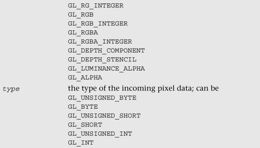
A 2D texture is the most basic and common form of texture in OpenGL ES. A 2D texture is—as you might guess—a two-dimensional array of image data. The individual data elements of a texture are known as texels (short for “texture pixels”). Texture image data in OpenGL ES can be represented in many different basic formats. The basic formats available for texture data are shown in Table 9-1.
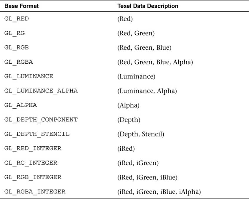
Table 9-1 Texture Base Formats
Each texel in the image is specified according to both its basic format and its data type. Later, we describe in more detail the various data types that can represent a texel. For now, the important point to understand is that a 2D texture is a two-dimensional array of image data. When rendering with a 2D texture, a texture coordinate is used as an index into the texture image. Generally, a mesh will be authored in a 3D content authoring program, with each vertex having a texture coordinate. Texture coordinates for 2D textures are given by a 2D pair of coordinates (s, t), sometimes also called (u, v) coordinates. These coordinates represent normalized coordinates used to look up a texture map, as shown in Figure 9-1.
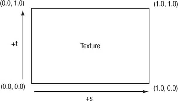
Figure 9-1 2D Texture Coordinates
The lower-left corner of the texture image is specified by the st-coordinates (0.0, 0.0). The upper-right corner of the texture image is specified by the st-coordinates (1.0, 1.0). Coordinates outside of the range [0.0, 1.0] are allowed, and the behavior of texture fetches outside of that range is defined by the texture wrapping mode (described in the section on texture filtering and wrapping).
Cubemap Textures
In addition to 2D textures, OpenGL ES 3.0 supports cubemap textures. At its most basic, a cubemap is a texture made up of six individual 2D texture faces. Each face of the cubemap represents one of the six sides of a cube. Although cubemaps have a variety of advanced uses in 3D rendering, the most common use is for an effect known as environment mapping. For this effect, the reflection of the environment onto the object is rendered by using a cubemap to represent the environment. Typically, a cubemap is generated for environment mapping by placing a camera in the center of the scene and capturing an image of the scene from each of the six axis directions (+X, –X, +Y, –Y, +Z, –Z) and storing the result in each cube face.
Texels are fetched out of a cubemap by using a 3D vector (s, t, r) as the texture coordinate to look up into the cubemap. The texture coordinates (s, t, r) represent the (x, y, z) components of the 3D vector. The 3D vector is used to first select a face of the cubemap to fetch from, and then the coordinate is projected into a 2D (s, t) coordinate to fetch from the cubemap face. The actual math for computing the 2D (s, t) coordinate is outside our scope here, but suffice it to say that a 3D vector is used to look up into a cubemap. You can visualize the way this process works by picturing a 3D vector coming from the origin inside of a cube. The point at which that vector intersects the cube is the texel that would be fetched from the cubemap. This concept is illustrated in Figure 9-2, where a 3D vector intersects the cube face.
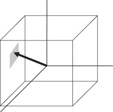
Figure 9-2 3D Texture Coordinate for Cubemap
The faces of a cubemap are each specified in the same manner as one would specify a 2D texture. Each of the faces must be square (e.g., the width and height must be equal), and each must have the same width and height. The 3D vector that is used for the texture coordinate is not normally stored directly on a per-vertex basis on the mesh as it is for 2D texturing. Instead, cubemaps are usually fetched from by using the normal vector as a basis for computing the cubemap texture coordinate. Typically, the normal vector is used along with a vector from the eye to compute a reflection vector that is then used to look up into a cubemap. This computation is described in the environment mapping example in Chapter 14, “Advanced Programming with OpenGL ES 3.0.”
3D Textures
Another type of texture in OpenGL ES 3.0 is the 3D texture (or volume texture). 3D textures can be thought of as an array of multiple slices of 2D textures. A 3D texture is accessed with a three-tuple (s, t, r) coordinate, much like a cubemap. For 3D textures, the r-coordinate selects which slice of the 3D texture to sample from and the (s, t) coordinate is used to fetch into the 2D map at each slice. Figure 9-3 shows a 3D texture where each slice is made up of an individual 2D texture. Each mipmap level in a 3D texture contains half the number of slices in the texture above it (more on this later).
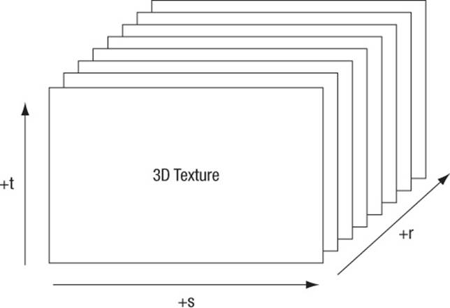
Figure 9-3 3D Texture
2D Texture Arrays
The final type of texture in OpenGL ES 3.0 is a 2D texture array. The 2D texture array is very similar to a 3D texture, but is used for a different purpose. For example, 2D texture arrays are often used to store an animation of a 2D image. Each slice of the array represents one frame of the texture animation. The difference between 2D texture arrays and 3D textures is subtle but important. For a 3D texture, filtering occurs between slices, whereas fetching from a 2D texture array will sample from only an individual slice. As such, mipmapping is also different. Each mipmap level in a 2D texture array contains the same number of slices as the level above it. Each 2D slice is entirely mipmapped independently from any other slices (unlike the case with a 3D texture, for which each mipmap level has half as many slices as above it).
To address a 2D texture array, three texture coordinates (s, t, r) are used just like with a 3D texture. The r-coordinate selects which slice in the 2D texture array to use and the (s, t) coordinates are used on the selected slice in exactly the same way as a 2D texture.
Texture Objects and Loading Textures
The first step in the application of textures is to create a texture object. A texture object is a container object that holds the texture data needed for rendering, such as image data, filtering modes, and wrap modes. In OpenGL ES, a texture object is represented by an unsigned integer that is a handle to the texture object. The function that is used for generating texture objects is glGenTextures.

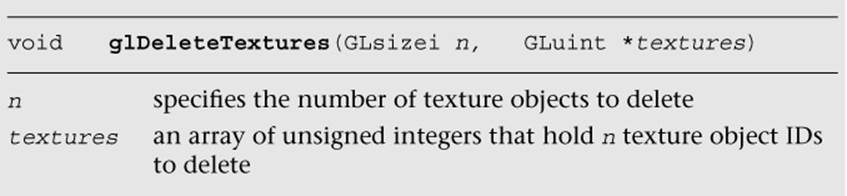
At the point of creation, the texture objects(s) generated by glGenTextures are an empty container that will be used for loading texture data and parameters. Texture objects also need to be deleted when an application no longer needs them. This step is typically done either at application shutdown or, for example, when changing levels in a game. It can be accomplished by using glDeleteTextures.
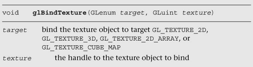
Once texture object IDs have been generated with glGenTextures, the application must bind the texture object to operate on it. Once texture objects are bound, subsequent operations such as glTexImage2D and glTexParameter affect the bound texture object. The function used to bind texture objects is glBindTexture.
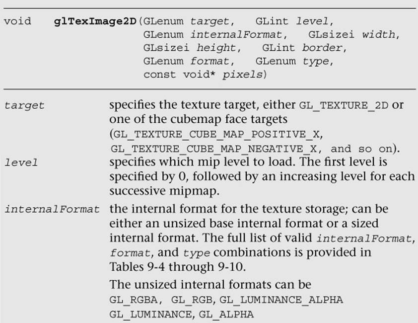
Once a texture is bound to a particular texture target, that texture object will remain bound to its target until it is deleted. After generating a texture object and binding it, the next step in using a texture is to actually load the image data. The basic function that is used for loading 2D and cubemap textures is glTexImage2D. In addition, several alternative methods may be used to specify 2D textures in OpenGL ES 3.0, including using immutable textures (glTexStorage2D) in conjunction with glTexSubImage2D. We start first with the most basic method—usingglTexImage2D—and describe immutable textures later in the chapter. For best performance, we recommend using immutable textures.
Example 9-1, from the Simple_Texture2D example, demonstrates generating a texture object, binding it, and then loading a 2 × 2 2D texture with RGB image data made from unsigned bytes.
Example 9-1 Generating a Texture Object, Binding It, and Loading Image Data
// Texture object handle
GLuint textureId;
// 2 x 2 Image, 3 bytes per pixel (R, G, B)
GLubyte pixels[4 * 3] =
{
255, 0, 0, // Red
0, 255, 0, // Green
0, 0, 255, // Blue
255, 255, 0 // Yellow
};
// Use tightly packed data
glPixelStorei(GL_UNPACK_ALIGNMENT, 1);
// Generate a texture object
glGenTextures(1, &textureId);
// Bind the texture object
glBindTexture(GL_TEXTURE_2D, textureId);
// Load the texture
glTexImage2D(GL_TEXTURE_2D, 0, GL_RGB, 2, 2, 0, GL_RGB,
GL_UNSIGNED_BYTE, pixels);
// Set the filtering mode
glTexParameteri(GL_TEXTURE_2D, GL_TEXTURE_MIN_FILTER,
GL_NEAREST);
glTexParameteri(GL_TEXTURE_2D, GL_TEXTURE_MAG_FILTER,
GL_NEAREST);
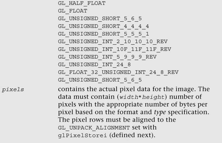
In the first part of the code, the pixels array is initialized with simple 2 × 2 texture data. The data is composed of unsigned byte RGB triplets that are in the range [0, 255]. When data is fetched from an 8-bit unsigned byte texture component in the shader, the values are mapped from the range [0, 255] to the floating-point range [0.0, 1.0]. Typically, an application would not create texture data in this simple manner, but rather would load the data from an image file. This example is provided to demonstrate the use of the API.
Prior to calling glTexImage2D, the application makes a call to glPixelStorei to set the unpack alignment. When texture data is uploaded via glTexImage2D, the rows of pixels are assumed to be aligned to the value set for GL_UNPACK_ALIGNMENT. By default, this value is 4, meaning that rows of pixels are assumed to begin on 4-byte boundaries. This application sets the unpack alignment to 1, meaning that each row of pixels begins on a byte boundary (in other words, the data is tightly packed). The full definition for glPixelStorei is given next.
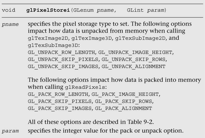
The GL_PACK_xxxxx arguments to glPixelStorei do not have any impact on texture image uploading. The pack options are used by glReadPixels, which is described in Chapter 11, “Fragment Operations.” The pack and unpack options set by glPixelStorei are global state and are not stored or associated with a texture object. In practice, it is rare to use any options other than GL_UNPACK_ALIGNMENT for specifying textures. For completeness, the full list of pixel storage options is provided in Table 9-2.
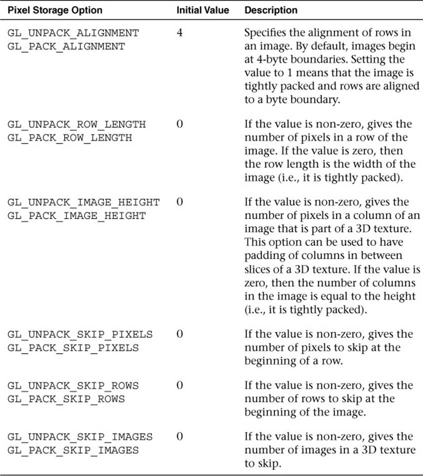
Table 9-2 Pixel Storage Options
Returning to the program in Example 9-1, after defining the image data, a texture object is generated using glGenTextures and then that object is bound to the GL_TEXTURE_2D target using glBindTexture. Finally, the image data is loaded into the texture object usingglTexImage2D. The format is set as GL_RGB, which signifies that the image data is composed of (R, G, B) triplets. The type is set as GL_UNSIGNED_BYTE, which signifies that each channel of the data is stored in an 8-bit unsigned byte. There are a number of other options for loading texture data, including the different formats described in Table 9-1. All of the texture formats are described later in this chapter in the Texture Formats section.
The last part of the code uses glTexParameteri to set the minification and magnification filtering modes to GL_NEAREST. This code is required because we have not loaded a complete mipmap chain for the texture; thus we must select a non-mipmapped minification filter. The other option would have been to use minification and magnification modes of GL_LINEAR, which provides bilinear non-mipmapped filtering. The details of texture filtering and mipmapping are explained in the next section.
Texture Filtering and Mipmapping
So far, we have limited our explanation of 2D textures to single 2D images. Although this allowed us to explain the concept of texturing, there is actually a bit more to how textures are specified and used in OpenGL ES. This complexity relates to the visual artifacts and performance issues that occur due to using a single texture map. As we have described texturing so far, the texture coordinate is used to generate a 2D index to fetch from the texture map. When the minification and magnification filters are set to GL_NEAREST, this is exactly what will happen: A single texel will be fetched at the texture coordinate location provided. This is known as point or nearest sampling.
However, nearest sampling might produce significant visual artifacts. The artifacts occur because as a triangle becomes smaller in screen space, the texture coordinates take large jumps when being interpolated from pixel to pixel. As a result, a small number of samples are taken from a large texture map, resulting in aliasing artifacts and a potentially large performance penalty. The solution that is used to resolve this type of artifact in OpenGL ES is known as mipmapping. The idea behind mipmapping is to build a chain of images known as a mipmap chain. The mipmap chain begins with the originally specified image and then continues with each subsequent image being half as large in each dimension as the one before it. This chain continues until we reach a single 1 × 1 texture at the bottom of the chain. The mip levels can be generated programmatically, typically by computing each pixel in a mip level as an average of the four pixels at the same location in the mip level above it (box filtering).
In the Chapter_9/MipMap2D sample program, we provide an example demonstrating how to generate a mipmap chain for a texture using a box filtering technique. The code to generate the mipmap chain is given by the GenMipMap2D function. This function takes an RGB8 image as input and generates the next mipmap level by performing a box filter on the preceding image. See the source code in the example for details on how the box filtering is done. The mipmap chain is then loaded using glTexImage2D, as shown in Example 9-2.
With a mipmap chain loaded, we can then set up the filtering mode to use mipmaps. The result is that we achieve a better ratio between screen pixels and texture pixels, thereby reducing aliasing artifacts. Aliasing is also reduced because each image in the mipmap chain is successively filtered so that high-frequency elements are attenuated more and more as we move down the chain.
Example 9-2 Loading a 2D Mipmap Chain
// Load mipmap level 0
glTexImage2D(GL_TEXTURE_2D, 0, GL_RGB, width, height,
0, GL_RGB, GL_UNSIGNED_BYTE, pixels);
level = 1;
prevImage = &pixels[0];
while(width > 1 && height > 1)
{
int newWidth,
newHeight;
// Generate the next mipmap level
GenMipMap2D(prevImage, &newImage, width, height, &newWidth,
&newHeight);
// Load the mipmap level
glTexImage2D(GL_TEXTURE_2D, level, GL_RGB,
newWidth, newHeight, 0, GL_RGB,
GL_UNSIGNED_BYTE, newImage);
// Free the previous image
free(prevImage);
// Set the previous image for the next iteration
prevImage = newImage;
level++;
// Half the width and height
width = newWidth;
height = newHeight;
}
free(newlmage);
Two types of filtering occur when texturing: minification and magnification. Minification is what happens when the size of the projected polygon on the screen is smaller than the size of the texture. Magnification is what happens when the size of the projected polygon on screen is larger than the size of the texture. The determination of which filter type to use is handled automatically by the hardware, but the API provides control over which type of filtering to use in each case. For magnification, mipmapping is not relevant, because we will always be sampling from the largest level available. For minification, a variety of sampling modes can be used. The choice of which mode to use is based on which level of visual quality you need to achieve and how much performance you are willing to give up for texture filtering.
The filtering modes are specified (along with many other texture options) with glTexParameter[i|f][v]. The texture filtering modes are described next, and the remaining options are described in subsequent sections.
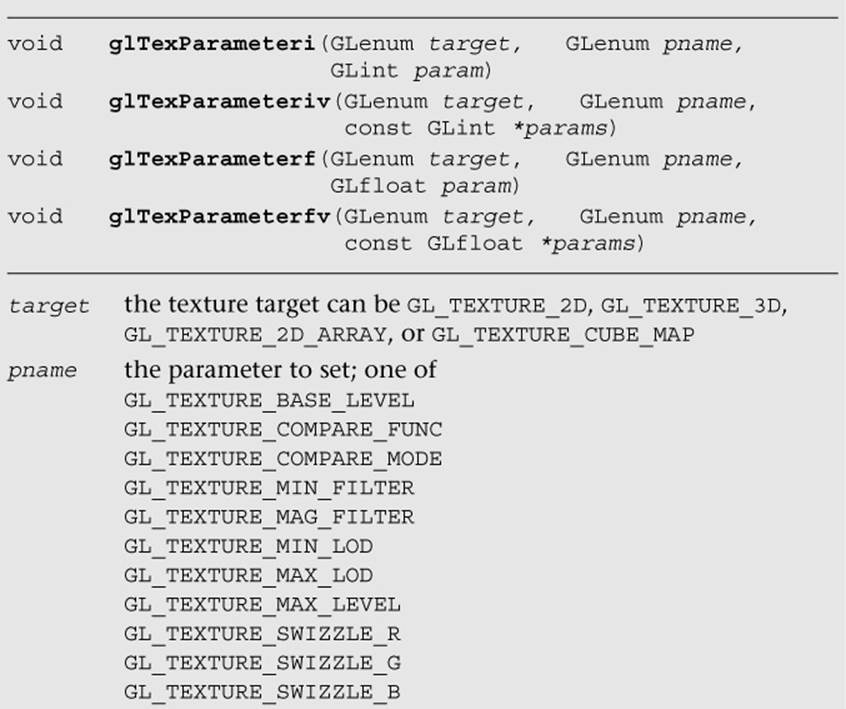
The magnification filter can be either GL_NEAREST or GL_LINEAR. In GL_NEAREST magnification filtering, a single point sample will be taken from the texture nearest to the texture coordinate. In GL_LINEAR magnification filtering, a bilinear (average of four samples) will be taken from the texture about the texture coordinate.
The minification filter can be set to any of the following values:
• GL_NEAREST—Takes a single point sample from the texture nearest to the texture coordinate.
• GL_LINEAR—Takes a bilinear sample from the texture nearest to the texture coordinate.
• GL_NEAREST_MIPMAP_NEAREST—Takes a single point sample from the closest mip level chosen.
• GL_NEAREST_MIPMAP_LINEAR—Takes a sample from the two closest mip levels and interpolates between those samples.
• GL_LINEAR_MIPMAP_NEAREST—Takes a bilinear fetch from the closest mip level chosen.
• GL_LINEAR_MIPMAP_LINEAR—Takes a bilinear fetch from each of the two closest mip levels and then interpolates between them. This last mode, which is typically referred to as trilinear filtering, produces the best quality of all modes.
Note
GL_NEAREST and GL_LINEAR are the only texture minification modes that do not require a complete mipmap chain to be specified for the texture. All of the other modes require that a complete mipmap chain exists for the texture.
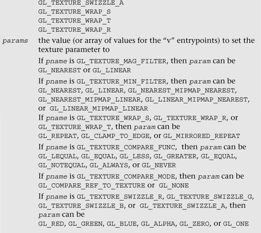
The MipMap2D example in Figure 9-4 shows the difference between a polygon drawn with GL_NEAREST versus GL_LINEAR_MIPMAP_LINEAR filtering.
Figure 9-4 MipMap2D: Nearest Versus Trilinear Filtering
It is worth mentioning some performance implications for the texture filtering mode that you choose. If minification occurs and performance is a concern, using a mipmap filtering mode is usually the best choice on most hardware. You tend to get very poor texture cache utilization without mipmaps because fetches happen at sparse locations throughout a map. However, the higher the filtering mode you use, the greater the performance cost in the hardware. For example, on most hardware, doing bilinear filtering is less costly than doing trilinear filtering. You should choose a mode that gives you the quality desired without unduly negatively impacting performance. On some hardware, you might get high-quality filtering virtually for free, particularly if the cost of the texture filtering is not your bottleneck. This is something that needs to be tuned for the application and hardware on which you plan to run your application.
Seamless Cubemap Filtering
One change with respect to filtering that is new to OpenGL ES 3.0 relates to how cubemaps are filtered. In OpenGL ES 2.0, when a linear filter kernel fell on the edge of a cubemap border, the filtering would happen on only a single cubemap face. This would result in artifacts at the borders between cubemap faces. In OpenGL ES 3.0, cubemap filtering is now seamless—if the filter kernel spans more than one cubemap face, the kernel will fetch samples from all of the faces it covers. Seamless filtering results in smoother filtering along cubemap face borders. In OpenGL ES 3.0, there is nothing you need to do to enable seamless cubemap filtering; all linear filter kernels will use it automatically.
Automatic Mipmap Generation
In the MipMap2D example in the previous section, the application created an image for level zero of the mipmap chain. It then generated the rest of the mipmap chain by performing a box filter on each image and successively halving the width and height. This is one way to generate mipmaps, but OpenGL ES 3.0 also provides a mechanism for automatically generating mipmaps using glGenerateMipmap.
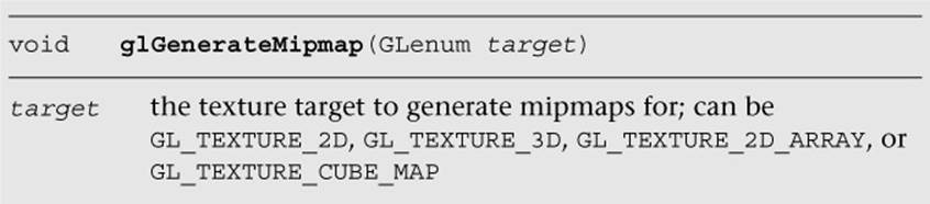
When calling glGenerateMipmap on a bound texture object, this function will generate the entire mipmap chain from the contents of the image in level zero. For a 2D texture, the contents of texture level zero will be successively filtered and used for each of the subsequent levels. For a cubemap, each of the cube faces will be generated from the level zero in each cube face. Of course, to use this function with cubemaps, you must have specified level zero for each cube face and each face must have a matching internal format, width, and height. For a 2D texture array, each slice of the array will be filtered as it would be for a 2D texture. Finally, for a 3D texture, the entire volume will be mipmapped by performing filtering across slices.
OpenGL ES 3.0 does not mandate that a particular filtering algorithm be used for generating mipmaps (although the specification recommends box filtering, implementations have latitude in choosing which algorithm they use). If you require a particular filtering method, then you will still need to generate the mipmaps on your own.
Automatic mipmap generation becomes particularly important when you start to use framebuffer objects for rendering to a texture. When rendering to a texture, we don’t want to have to read back the contents of the texture to the CPU to generate mipmaps. Instead, glGenerateMipmapcan be used and the graphics hardware can then potentially generate the mipmaps without ever having to read the data back to the CPU. When we cover framebuffer objects in more detail in Chapter 12, “Framebuffer Objects,” this point should become clear.
Texture Coordinate Wrapping
Texture wrap modes are used to specify the behavior that occurs when a texture coordinate is outside of the range [0.0, 1.0]. The texture wrap modes are set using glTexParameter[i|f][v]. Such modes can be set independently for the s-coordinate, t-coordinate, and r-coordinate. TheGL_TEXTURE_WRAP_S mode defines what the behavior is when the s-coordinate is outside of the range [0.0, 1.0], GL_TEXTURE_WRAP_T sets the behavior for the t-coordinate, and GL_TEXTURE_WRAP_R sets the behavior for the r-coordinate (the r-coordinate wrapping is used only for 3D textures and 2D texture arrays). In OpenGL ES, there are three wrap modes to choose from, as described in Table 9-3.
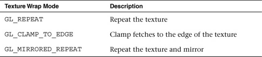
Table 9-3 Texture Wrap Modes
Note that the texture wrap modes also affect the behavior of filtering. For example, when a texture coordinate is at the edge of a texture, the bilinear filter kernel might span beyond the edge of the texture. In this case, the wrap mode will determine which texels are fetched for the portion of the kernel that lies outside the texture edge. You should use GL_CLAMP_TO_EDGE whenever you do not want any form of repeating.
In Chapter_9/TextureWrap, there is an example that draws a quad with each of the three different texture wrap modes. The quads have a checkerboard image applied to them and are rendered with texture coordinates in the range from [–1.0, 2.0]. The results are shown in Figure 9-5.
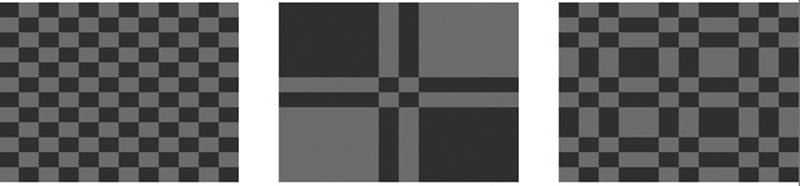
Figure 9-5 GL_REPEAT, GL_CLAMP_TO_EDGE, and GL_MIRRORED_REPEAT Modes
The three quads are rendered using the following setup code for the texture wrap modes:
// Draw left quad with repeat wrap mode
glTexParameteri(GL_TEXTURE_2D, GL_TEXTURE_WRAP_S, GL_REPEAT);
glTexParameteri(GL_TEXTURE_2D, GL_TEXTURE_WRAP_T, GL_REPEAT);
glUniformlf(userData->offsetLoc, -0.7f);
glDrawElements(GL_TRIANGLES, 6, GL_UNSIGNED_SHORT, indices);
// Draw middle quad with clamp to edge wrap mode
glTexParameteri(GL_TEXTURE_2D, GL_TEXTURE_WRAP_S,
GL_CLAMP_TO_EDGE);
glTexParameteri(GL_TEXTURE_2D, GL_TEXTURE_WRAP_T,
GL_CLAMP_TO_EDGE);
glUniformlf(userData->offsetLoc, 0.0f);
glDrawElements(GL_TRIANGLES, 6, GL_UNSIGNED_SHORT, indices);
// Draw right quad with mirrored repeat
glTexParameteri(GL_TEXTURE_2D, GL_TEXTURE_WRAP_S,
GL_MIRRORED_REPEAT);
glTexParameteri(GL_TEXTURE_2D, GL_TEXTURE_WRAP_T,
GL_MIRRORED_REPEAT);
glUniformlf(userData->offsetLoc, 0.7f);
glDrawElements GL_TRIANGLES, 6, GL_UNSIGNED_SHORT, indices);
In Figure 9-5, the quad on the far left is rendered using GL_REPEAT mode. In this mode, the texture simply repeats outside of the range [0, 1], resulting in a tiling pattern of the image. The quad in the center is rendered with GL_CLAMP_TO_EDGE mode. As you can see, when the texture coordinates go outside the range [0, 1], the texture coordinates are clamped to sample from the edge of the texture. The quad on the right is rendered with GL_MIRRORED_REPEAT, which mirrors and then repeats the image when the texture coordinates are outside the range [0, 1].
Texture Swizzles
Texture swizzles control how color components in the input R, RG, RGB, or RGBA texture map to components when fetched from in the shader. For example, an application might want a GL_RED texture to map to (0, 0, 0, R) or (R, R, R, 1) as opposed to the default mapping of (R, 0, 0, 1). The texture component that each R, G, B, and A value maps to can be independently controlled using texture swizzles set using glTexParameter[i|f][v]. The component to control is set by using GL_TEXTURE_SWIZZLE_R, GL_TEXTURE_SWIZZLE_G,GL_TEXTURE_SWIZZLE_B, or GL_TEXTURE_SWIZZLE_A. The texture value that will be the source for that component can be either GL_RED, GL_GREEN, GL_BLUE, or GL_ALPHA to fetch from the R, G, B, or A component, respectively. Additionally, the application can set the value to be the constant 0 or 1 using GL_ZERO or GL_ONE, respectively.
Texture Level of Detail
In some applications, it is useful to be able to start displaying a scene before all of the texture mipmap levels are available. For example, a GPS application that is downloading texture images over a data connection might start with the lowest-level mipmaps and display the higher levels when they become available. In OpenGL ES 3.0, this can be accomplished by using several of the arguments to glTexParameter[i|f][v]. The GL_TEXTURE_BASE_LEVEL sets the largest mipmap level that will be used for a texture. By default, this has a value of 0, but it can be set to a higher value if mipmap levels are not yet available. Likewise, GL_TEXTURE_MAX_LEVEL sets the smallest mipmap level that will be used. By default, it has a value of 1000 (beyond the largest level any texture could have), but it can be set to a lower number to control the smallest mipmap level to use for a texture.
To select which mipmap level to use for rendering, OpenGL ES automatically computes a level of detail (LOD) value. This floating-point value determines which mipmap level to filter from (and in trilinear filtering, controls how much of each mipmap is used). An application can also control the minimum and maximum LOD values with GL_TEXTURE_MIN_LOD and GL_TEXTURE_MAX_LOD. One reason it is useful to be able to control the LOD clamp separately from the base and maximum mipmap levels is to provide smooth transitioning when new mipmap levels become available. Setting just the texture base and maximum level might result in a popping artifact when new mipmap levels are available, whereas interpolating the LOD can make this transition look smoother.
Depth Texture Compare (Percentage Closest Filtering)
The last texture parameters to discuss are GL_TEXTURE_COMPARE_FUNC and GL_TEXTURE_COMPARE_MODE. These texture parameters were introduced to provide a feature known as percentage closest filtering (PCF). When performing the shadowing technique known as shadow mapping, the fragment shader needs to compare the current depth value of a fragment to the depth value in a depth texture to determine whether a fragment is within or outside of the shadow. To achieve smoother-looking shadow edges, it is useful to be able to perform bilinear filtering on the depth texture. However, when filtering a depth texture, we want the filtering to occur after we sample the depth value and compare to the current depth (or reference value). If filtering were to occur before comparison, then we would be averaging values in the depth texture, which does not provide the correct result. PCF provides the correct filtering, such that each depth value sampled is compared to the reference depth and then the results of those comparisons (0 or 1) are averaged together.
The GL_TEXTURE_COMPARE_MODE defaults to GL_NONE, but when it is set to GL_COMPARE_REF_TO_TEXTURE, the r-coordinate in the (s, t, r) texture coordinate will be compared with the value of the depth texture. The result of this comparison then becomes the result of the shadow texture fetch (either a value of 0 or 1, or an averaging of these values if texture filtering is enabled). The comparison function is set using GL_TEXTURE_COMPARE_FUNC, which can set the comparison function to GL_LEQUAL, GL_EQUAL, GL_LESS, GL_GREATER, GL_EQUAL,GL_NOTEQUAL, GL_ALWAYS, or GL_NEVER. More details on shadow mapping are covered in Chapter 14, “Advanced Programming with OpenGL ES 3.0.”
Texture Formats
OpenGL ES 3.0 offers a wide range of data formats for textures. In fact, the number of formats has greatly increased from OpenGL ES 2.0. This section details the texture formats available in OpenGL ES 3.0.
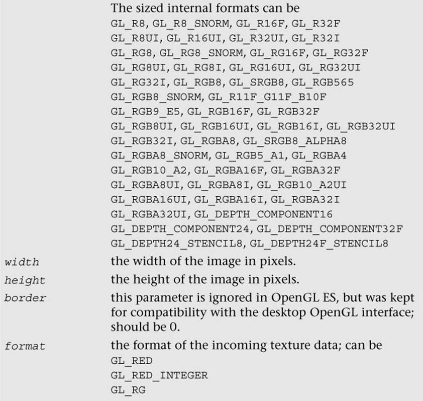
As described in the previous section Texture Objects and Loading Textures, a 2D texture can be uploaded with either an unsized or sized internal format using glTexImage2D. If the texture is specified with an unsized format, the OpenGL ES implementation is free to choose the actual internal representation in which the texture data is stored. If the texture is specified with a sized format, then OpenGL ES will choose a format with at least as many bits as is specified.
Table 9-4 lists the valid combinations for specifying a texture with an unsized internal format.
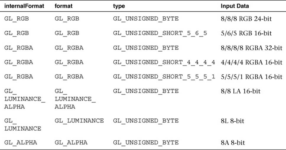
Table 9-4 Valid Unsized Internal Format Combinations for glTexImage2D
If the application wants more control over how the data is stored internally, then it can use a sized internal format. The valid combinations for sized internal formats with glTexImage2D are listed in Tables 9-5 to 9-10. In the last two columns, “R” means renderable and “F” means filterable. OpenGL ES 3.0 mandates only that certain formats be available for rendering to or filtering from. Further, some formats can be specified with input data containing more bits than the internal format. In this case, the implementation may choose to convert to lesser bits or use a format with more bits.
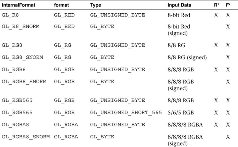
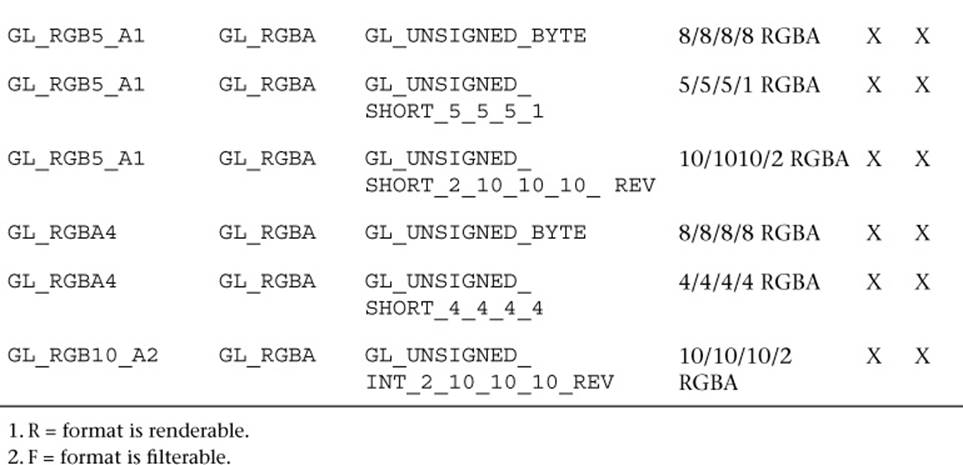
Table 9-5 Normalized Sized Internal Format Combinations for glTexImage2D
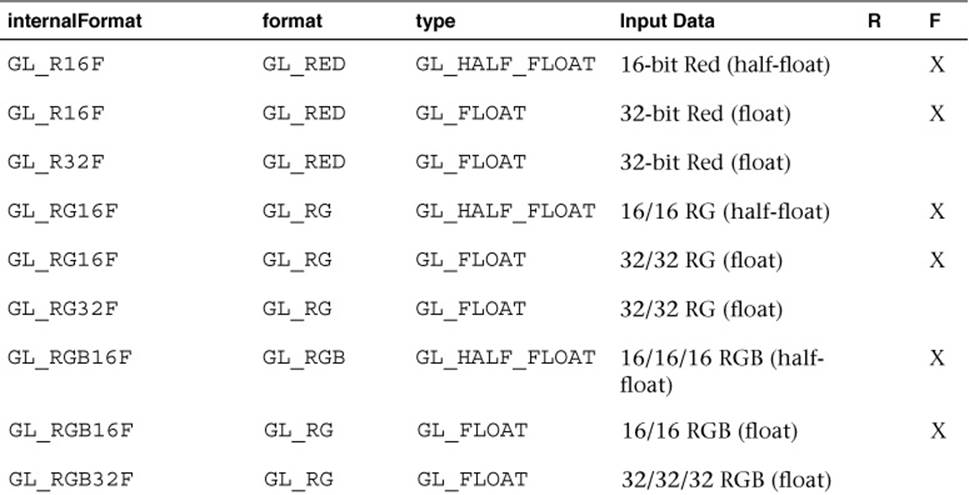
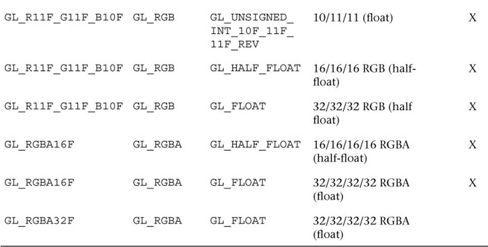
Table 9-6 Valid Sized Floating-Point Internal Format Combinations for glTexImage2D
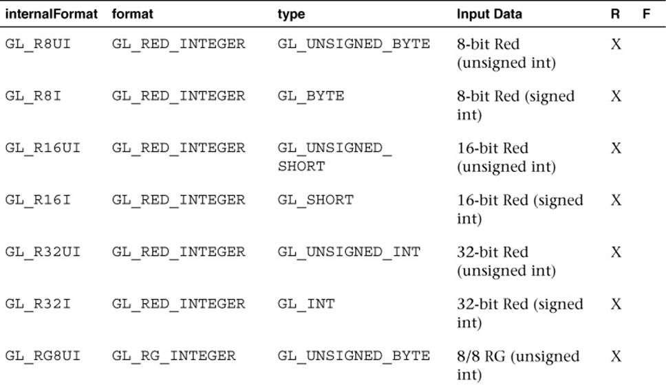
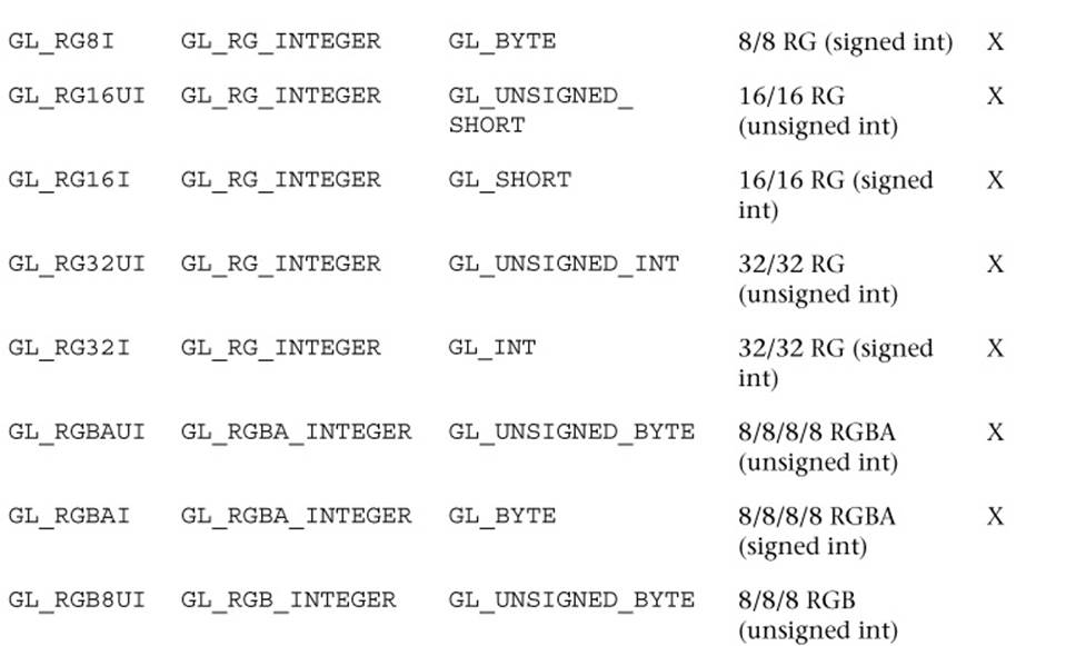
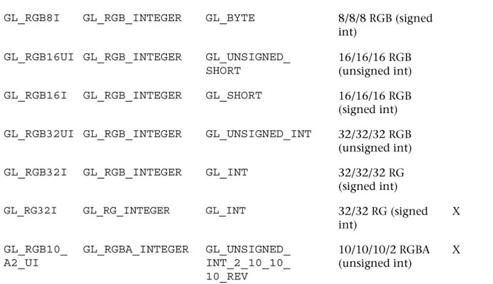
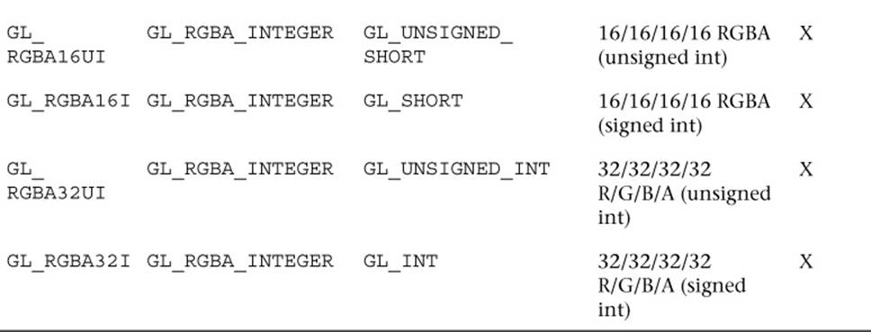
Table 9-7 Valid Sized Internal Integer Texture Format Combinations for glTexImage2D
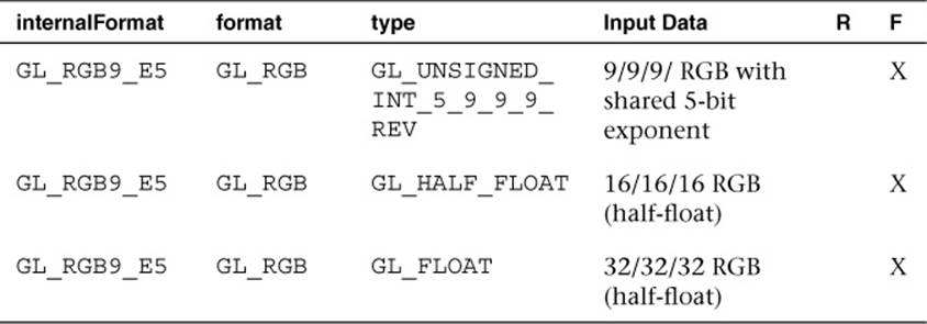
Table 9-8 Valid Shared Exponent Sized Internal Format Combinations for glTexImage2D
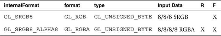
Table 9-9 Valid sRGB Sized Internal Format Combinations for glTexImage2D
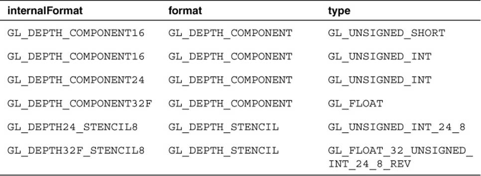
Table 9-10 Valid Depth Sized Internal Format Combinations for glTexImage2D
To explain the large variety of texture formats in OpenGL ES 3.0, we have organized them into the following categories: normalized texture formats, floating-point textures, integer textures, shared exponent textures, sRGB textures, and depth textures.
Normalized Texture Formats
Table 9-5 lists the set of internal format combinations that can be used to specify normalized texture formats. By “normalized,” we mean that the results when fetched from the texture in the fragment shader will be in the [0.0, 1.0] range (or [–1.0, 1.0] range in the case of *_SNORM formats). For example, a GL_R8 image specified with GL_UNSIGNED_BYTE data will take each 8-bit unsigned byte value in the range from [0, 255] and map it to [0.0, 1.0] when fetched in the fragment shader. A GL_R8_SNORM image specified with GL_BYTE data will take each 8-bit signed byte value in the range from [–128, 127] and map it to [–1.0, 1.0] when fetched.
The normalized formats can be specified with between one and four components per texel (R, RG, RGB, or RGBA). OpenGL ES 3.0 also introduces GL_RGB10_A2, which allows the specification of texture image data with 10 bits for each (R, G, B) value and 2 bits for each alpha value.
Floating-Point Texture Formats
OpenGL ES 3.0 also introduces floating-point texture formats. The majority of the floating-point formats are backed by either 16-bit half-floating-point data (described in detail in Appendix A) or 32-bit floating-point data. Floating-point texture formats can have one to four components, just like normalized texture formats (R, RG, RGB, RGBA). OpenGL ES 3.0 does not mandate that floating-point formats be used as render targets, and only 16-bit half-floating-point data is mandated to be filterable.
In addition to 16-bit and 32-bit floating-point data, OpenGL ES 3.0 introduces the 11/11/10 GL_R11F_G11F_B10F floating-point format. The motivation for this format is to provide higher-precision, three-channel textures while still keeping the storage of each texel at 32 bits. The use of this format may lead to higher performance than a 16/16/16 GL_RGB16F or 32/32/32 GL_RGB32F texture. This format has 11 bits for the Red and Green channel and 10 bits for the Blue channel. For the 11-bit Red and Green values, there are 6 bits of mantissa and 5 bits of exponent; the 10-bit Blue value has 5 bits of mantissa and 5 bits of exponent. The 11/11/10 format can be used only to represent positive values because there is no sign bit for any of the components. The largest value that can be represented in the 11-bit and 10-bit formats is 6.5 × 10⁴ and the smallest value is 6.1 × 10⁻⁵. The 11-bit format has 2.5 decimal digits of precision, and the 10-bit format has 2.32 decimal digits of precision.
Integer Texture Formats
Integer texture formats allow the specification of textures that can be fetched as integers in the fragment shader. That is, as opposed to normalized texture formats where the data are converted from their integer representation to a normalized floating-point value upon fetch in the fragment shader, the values in integer textures remain as integers when fetched in the fragment shader.
Integer texture formats are not filterable, but the R, RG, and RGBA variants can be used as a color attachment to render to in a framebuffer object. When using an integer texture as a color attachment, the alpha blend state is ignored (no blending is possible with integer render targets). The fragment shader used to fetch from integer textures and to output to an integer render target should use the appropriate signed or unsigned integer type that corresponds with the format.
Shared Exponent Texture Formats
Shared exponent textures provide a way to store RGB textures that have a large range without requiring as much bit depth as used by floating-point textures. Shared exponent textures are typically used for high dynamic range (HDR) images where half- or full-floating-point data are not required. The shared exponent texture format in OpenGL ES 3.0 is GL_RGB9_E5. In this format, one 5-bit exponent is shared by all three RGB components. The 5-bit exponent is implicitly biased by the value 15. Each of the 9-bit values for RGB store the mantissa without a sign bit (and thus must be positive).
Upon fetch, the three RGB values are derived from the texture using the following equations:
Rout = Rin *2(EXP – 15)
Gout = Gin *2(EXP – 15)
Bout = Bin *2(EXP – 15)
If the input texture is specified in 16-bit half-float or 32-bit float, then the OpenGL ES implementation will automatically convert to the shared exponent format. The conversion is done by first determining the maximum color value:
MAXc = max(R,G,B)
The shared exponent is then computed using the following formula:
EXP = max (–16, floor(log2 (MAXc))) +16
Finally, the 9-bit mantissa values for RGB are computed as follows:
Rs = floor (R/(2(EXP – 15 + 9)) + 0.5)
Gs = floor (G/(2(EXP – 15 + 9)) + 0.5)
Bs = floor (B/(2(EXP – 15 + 9)) + 0.5)
An application could use these conversion formulas to derive the 5-bit EXP and 9-bit RGB values from incoming data, or it can simply pass in the 16-bit half-float or 32-bit float data to OpenGL ES and let it perform the conversion.
sRGB Texture Formats
Another texture format introduced in OpenGL ES 3.0 is sRGB textures. sRGB is a nonlinear colorspace that approximately follows a power function. Most images are actually stored in the sRGB colorspace, as the nonlinearity accounts for the fact that humans can differentiate color better at different brightness levels.
If the images used for textures are authored in the sRGB colorspace but are fetched without using sRGB textures, all of the lighting calculations that occur in the shader happen in a nonlinear colorspace. That is, the textures created in standard authoring packages are stored in sRGB and remain in sRGB when fetched from in the shader. The lighting calculations then are occurring in the nonlinear sRGB space. While many applications make this mistake, it is not correct and actually results in discernibly different (and incorrect) output image.
To properly account for sRGB images, an application should use an sRGB texture format that will be converted from sRGB into a linear colorspace on fetch in the shader. Then, all calculations in the shader are done in linear colorspace. Finally, by rendering to a sRGB render target, the image will be correctly converted back to sRGB on write. It is possible to approximate sRGB → linear conversion using a shader instructionpow(value, 2.2) and then to approximate the linear → sRGB conversion using pow(value, 1/2.2). However, it is preferable to use a sRGB texture where possible because it reduces the shader instructions and provides a more correct sRGB conversion.
Depth Texture Formats
The final texture format type in OpenGL ES 3.0 is depth textures. Depth textures allow the application to fetch the depth (and optionally, stencil) value from the depth attachment of a framebuffer object. This is useful in a variety of advanced rendering algorithms, including shadow mapping.Table 9-10 lists the valid depth texture formats in OpenGL ES 3.0.
Using Textures in a Shader
Now that we have covered the basics of setting up texturing, let’s look at some sample shader code. The vertex–fragment shader pair in Example 9-3 from the Simple_Texture2D sample demonstrates the basics of how 2D texturing is done in a shader.
Example 9-3 Vertex and Fragment Shaders for Performing 2D Texturing
// Vertex shader
#version 300 es
layout(location = 0) in vec4 a_position;
layout(location = 1) in vec2 a_texCoord;
out vec2 v_texCoord;
void main()
{
gl_Position = a_position;
v_texCoord = a_texCoord;
}
// Fragment shader
#version 300 es
precision mediump float;
in vec2 v_texCoord;
layout(location = 0) out vec4 outColor;
uniform sampler2D s_texture;
void main()
{
outColor = texture( s_texture, v_texCoord );
}
The vertex shader takes in a two-component texture coordinate as a vertex input and passes it as an output to the fragment shader. The fragment shader consumes that texture coordinate and uses it for the texture fetch. The fragment shader declares a uniform variable of type sampler2Dcalled s_texture. A sampler is a special type of uniform variable that is used to fetch from a texture map. The sampler uniform will be loaded with a value specifying the texture unit to which the texture is bound; for example, specifying that a sampler with a value of 0 says to fetch from unit GL_TEXTURE0, specifying a value of 1 says to fetch from GL_TEXTURE1, and so on. Textures are bound to texture units in the OpenGL ES 3.0 API by using the glActiveTexture function.
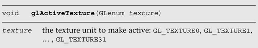
The function glActiveTexture sets the current texture unit so that subsequent calls to glBindTexture will bind the texture to the currently active unit. The number of texture units available to the fragment shader on an implementation of OpenGL ES can be queried for by usingglGetintegerv with the parameter GL_MAX_TEXTURE_IMAGE_UNITS. The number of texture units available to the vertex shader can be queried for by using glGetIntegerv with the parameter GL_MAX_VERTEX_TEXTURE_IMAGE_UNITS.
The following example code from the Simple_Texture2D example shows how the sampler and texture are bound to the texture unit.
// Get the sampler locations
userData->samplerLoc = glGetUniformLocation(
userData->programObject,
"s_texture");
// ...
// Bind the texture
glActiveTexture(GL_TEXTURE0);
glBindTexture(GL_TEXTURE_2D, userData->textureId);
// Set the sampler texture unit to 0
glUniformli(userData->samplerLoc, 0);
At this point, we have the texture loaded, the texture bound to texture unit 0, and the sampler set to use texture unit 0. Going back to the fragment shader in the Simple_Texture2D example, we see that the shader code then uses the built-in function texture to fetch from the texture map. The texture built-in function takes the form shown here:
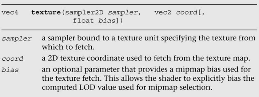
The texture function returns a vec4 representing the color fetched from the texture map. The way the texture data is mapped into the channels of this color depends on the base format of the texture. Table 9-11 shows the way in which texture formats are mapped to vec4 colors. The texture swizzle (described in the Texture Swizzles section earlier in this chapter) determines how the values from each of these components map to components in the shader.
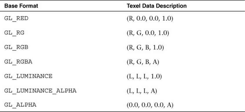
Table 9-11 Mapping of Texture Formats to Colors
In the case of the Simple_Texture2D example, the texture was loaded as GL_RGB and the texture swizzles were left at the default values, so the result of the texture fetch will be a vec4 with values (R, G, B, 1.0).
Example of Using a Cubemap Texture
Using a cubemap texture is very similar to using a 2D texture. The example Simple_TextureCubemap demonstrates drawing a sphere with a simple cubemap. The cubemap contains six 1 × 1 faces, each with a different color. The code in Example 9-4 is used to load the cubemap texture.
Example 9-4 Loading a Cubemap Texture
GLuint CreateSimpleTextureCubemap()
{
GLuint textureId;
// Six l x l RGB faces
GLubyte cubePixels[6][3] =
{
// Face 0 - Red
255, 0, 0,
// Face 1 - Green,
0, 255, 0,
// Face 2 - Blue
0, 0, 255,
// Face 3 - Yellow
255, 255, 0,
// Face 4 - Purple
255, 0, 255,
// Face 5 - White
255, 255, 255
};
// Generate a texture object
glGenTextures(1, &textureId);
// Bind the texture object
glBindTexture(GL_TEXTURE_CUBE_MAP, textureId);
// Load the cube face - Positive X
glTexImage2D(GL_TEXTURE_CUBE_MAP_POSITIVE_X, 0, GL_RGB, 1, 1,
0, GL_RGB, GL_UNSIGNED_BYTE, &cubePixels[0]);
// Load the cube face - Negative X
glTexImage2D(GL_TEXTURE_CUBE_MAP_NEGATIVE_X, 0, GL_RGB, 1, 1,
0, GL_RGB, GL_UNSIGNED_BYTE, &cubePixels[1]);
// Load the cube face - Positive Y
glTexImage2D(GL_TEXTURE_CUBE_MAP_POSITIVE_Y, 0, GL_RGB, 1, 1,
0, GL_RGB, GL_UNSIGNED_BYTE, &cubePixels[2]);
// Load the cube face - Negative Y
glTexImage2D(GL_TEXTURE_CUBE_MAP_NEGATIVE_Y, 0, GL_RGB, 1, 1,
0, GL_RGB, GL_UNSIGNED_BYTE, &cubePixels[3]);
// Load the cube face - Positive Z
glTexImage2D(GL_TEXTURE_CUBE_MAP_POSITIVE_Z, 0, GL_RGB, 1, 1,
0, GL_RGB, GL_UNSIGNED_BYTE, &cubePixels[4]);
// Load the cube face - Negative Z
glTexImage2D(GL_TEXTURE_CUBE_MAP_NEGATIVE_Z, 0, GL_RGB, 1, 1,
0, GL_RGB, GL_UNSIGNED_BYTE, &cubePixels[5]);
// Set the filtering mode
glTexParameteri(GL_TEXTURE_CUBE_MAP, GL_TEXTURE_MIN_FILTER,
GL_NEAREST);
glTexParameteri(GL_TEXTURE_CUBE_MAP, GL_TEXTURE_MAG_FILTER,
GL_NEAREST);
return textureId;
}
This code loads each individual cubemap face with l × l RGB pixel data by calling glTexImage2D for each cubemap face. The shader code to render the sphere with a cubemap is provided in Example 9-5.
Example 9-5 Vertex and Fragment Shader Pair for Cubemap Texturing
// Vertex shader
#version 300 es
layout(location = 0) in vec4 a_position;
layout(location = 1) in vec3 a_normal;
out vec3 v_normal;
void main()
{
gl_Position = a_position;
v_normal = a_normal;
}
// Fragment shader
#version 300 es
precision mediump float;
in vec3 v_normal;
layout(location = 0) out vec4 outColor;
uniform samplerCube s_texture;
void main()
{
outColor = texture( s_texture, v_normal );
}
The vertex shader takes in a position and a normal as vertex inputs. A normal is stored at each vertex of the sphere that will be used as a texture coordinate. The normal is passed to the fragment shader. The fragment shader then uses the built-in function texture to fetch from the cubemap using the normal as a texture coordinate. The texture built-in function for cubemaps takes the form shown here:
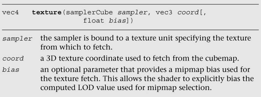
The function for fetching a cubemap is very similar to a 2D texture. The only difference is that the texture coordinate has three components instead of two and the sampler type must be samplerCube. The same method is used to bind the cubemap texture and load the sampler as is used for the Simple_Texture2D example.
Loading 3D Textures and 2D Texture Arrays
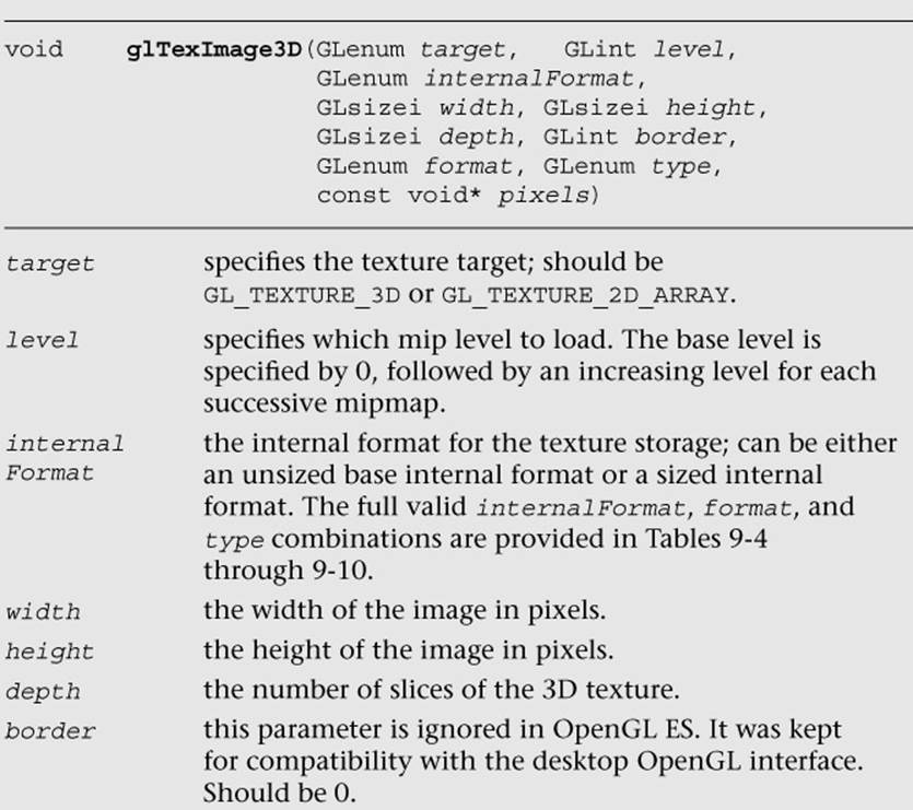
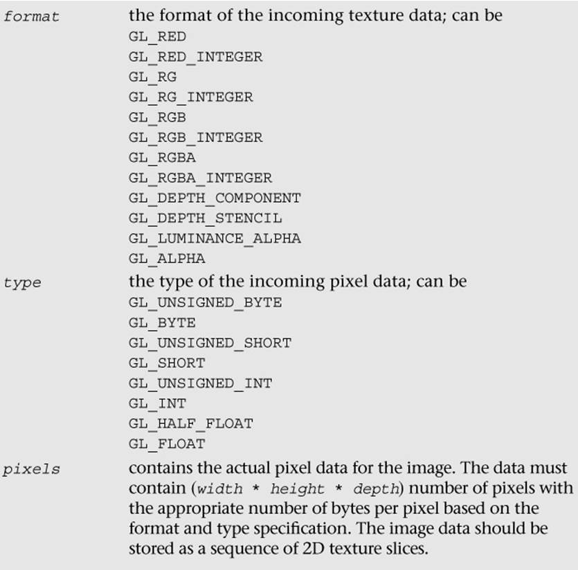
As discussed earlier in the chapter, in addition to 2D textures and cubemaps, OpenGL ES 3.0 includes 3D textures and 2D texture arrays. The function to load 3D textures and 2D texture arrays is glTexImage3D, which is very similar to glTexImage2D.
Once a 3D texture or 2D texture array has been loaded using glTexImage3D, the texture can be fetched in the shader using the texture built-in function.
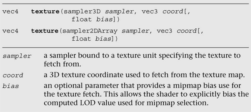
Note that the r-coordinate is a floating-point value. For 3D textures, depending on the filtering mode set, the texture fetch might span two slices of the volume.
Compressed Textures
Thus far, we have been dealing with textures that were loaded with uncompressed texture image data. OpenGL ES 3.0 also supports the loading of compressed texture image data. There are several reasons why compressing textures is desirable. The first and obvious reason to compress textures is to reduce the memory footprint of the textures on the device. A second, less obvious reason to compress textures is that a memory bandwidth savings occurs when you fetch from compressed textures in a shader. Finally, compressed textures might allow you to reduce the download size of your application by reducing the amount of image data that must be stored.
In OpenGL ES 2.0, the core specification did not define any compressed texture image formats. That is, the OpenGL ES 2.0 core simply defined a mechanism whereby compressed texture image data could be loaded, but no compressed formats were defined. As a result, many vendors, including Qualcomm, ARM, Imagination Technologies, and NVIDIA, provided hardware-specific texture compression extensions. In turn, developers of OpenGL ES 2.0 applications had to support different texture compression formats on different platforms and hardware.
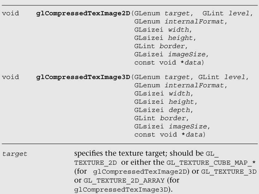
OpenGL ES 3.0 has improved this situation by introducing standard texture compression formats that all vendors must support. Ericsson Texture Compression (ETC2 and EAC) was offered as a royalty-free standard to Khronos, and it was adopted as the standard texture compression format for OpenGL ES 3.0. There are variants of EAC for compressing one- and two-channel data as well as variants of ETC2 for compressing three- and four-channel data. The function used to load compressed image data for 2D textures and cubemaps is glCompressedTexImage2D; the corresponding function for 2D texture arrays is glCompressedTexImage3D. Note that ETC2/EAC is not supported for 3D textures (only 2D textures and 2D texture arrays), but glCompressedTexImage3D can be used to potentially load vendor-specific 3D texture compression formats.
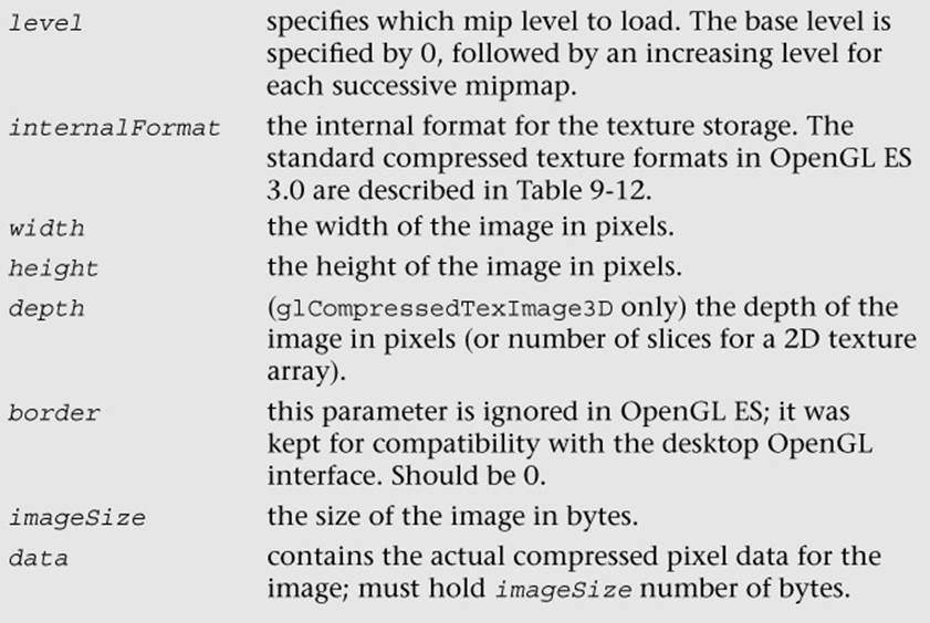
The standard ETC compressed texture formats supported by OpenGL ES 3.0 are listed in Table 9-12. All of the ETC formats store compressed image data in 4 × 4 blocks. Table 9-12 lists the number of bits per pixel in each of the ETC formats. The size of an individual ETC image can be computed from the bits-per-pixel (bpp) ratio as follows:
sizeInBytes = max(width, 4) * max(height, 4) * bpp/8
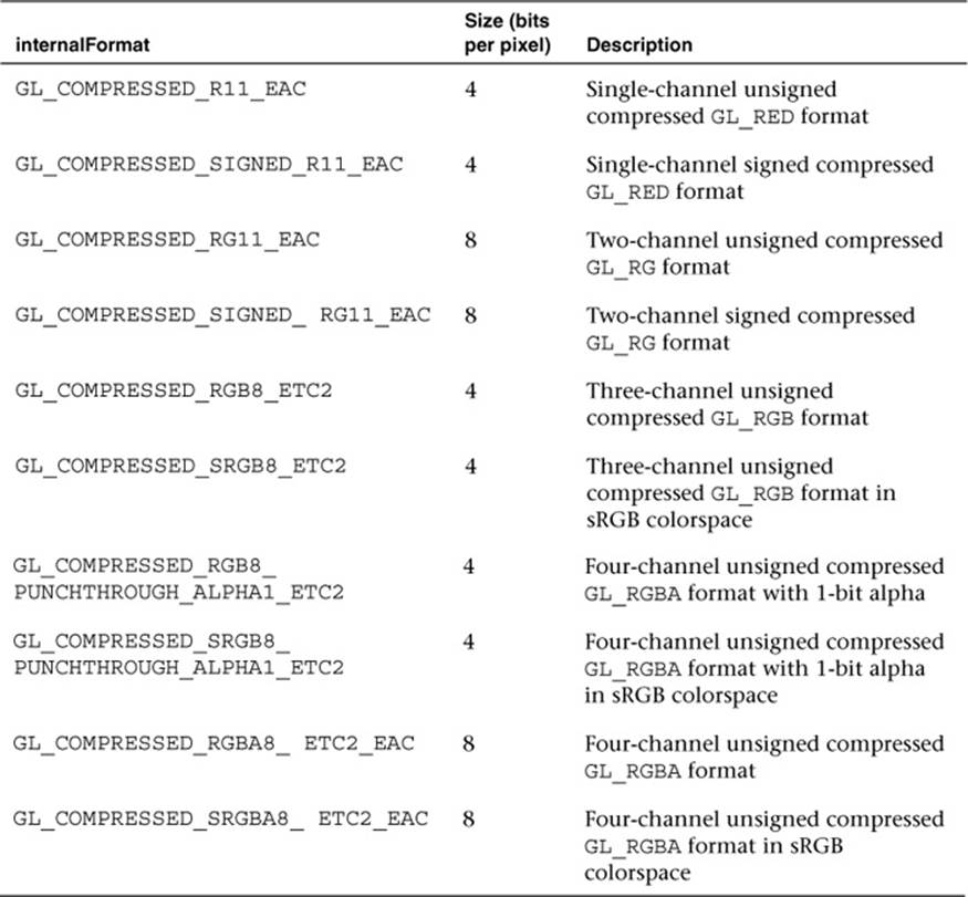
Table 9-12 Standard Texture Compression Formats
Once a texture has been loaded as a compressed texture, it can be used for texturing in exactly the same way as an uncompressed texture. The details of the ETC2/EAC formats are beyond our scope here, and most developers will never write their own compressors. Freely available tools for generating ETC images include the open-source libKTX library from Khronos (http://khronos.org/opengles/sdk/tools/KTX/), the rg_etc project (https://code.google.com/p/rg-etc1/), the ARM Mali Texture Compression Tool, Qualcomm TexCompress (included in the Adreno SDK), and Imagination Technologies PVRTexTool. We would encourage readers to evaluate the available tools and choose the one that fits best with their development environment/platform.
Note that all implementations of OpenGL ES 3.0 will support the formats listed in Table 9-12. In addition, some implementations may support vendor-specific compressed formats not listed in Table 9-12. If you attempt to use a texture compression format on an OpenGL ES 3.0 implementation that does not support it, a GL_INVALID_ENUM error will be generated. It is important that you check that the OpenGL ES 3.0 implementation exports the extension string for any vendor-specific texture compression format you use. If it does not, you must fall back to using an uncompressed texture format.
In addition to checking extension strings, there is another method you can use to determine which texture compression formats are supported by an implementation. That is, you can query for GL_NUM_COMPRESSED_TEXTURE_FORMATS using glGetIntegerv to determine the number of compressed image formats supported. You can then query for GL_COMPRESSED_TEXTURE_FORMATS using glGetIntegerv, which will return an array of GLenum values. Each GLenum value in the array will be a compressed texture format that is supported by the implementation.
Texture Subimage Specification
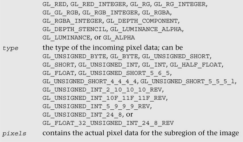
After uploading a texture image using glTexImage2D, it is possible to update portions of the image. This ability would be useful if you wanted to update just a subregion of an image. The function to load a portion of a 2D texture image is glTexSubImage2D.
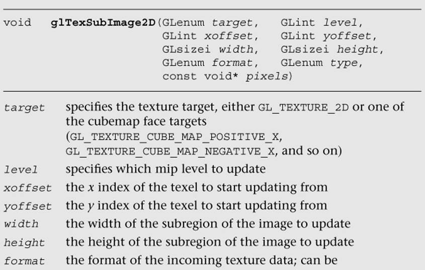
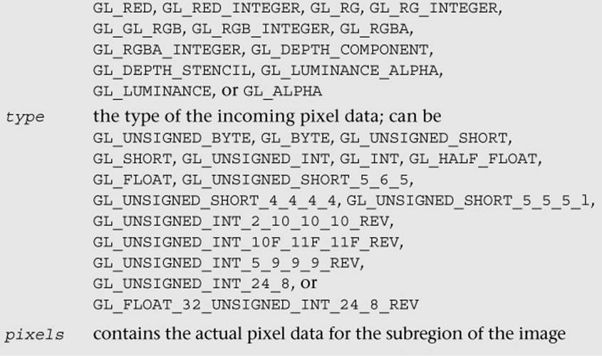
This function will update the region of texels in the range (xoffset, yoffset) to (xoffset + width – 1, yoffset + height – 1). Note that to use this function, the texture must already be fully specified. The range of the subimage must be within the bounds of the previously specified texture image. The data in the pixels array must be aligned to the alignment that is specified by GL_UNPACK_ALIGNMENT with glPixelStorei.
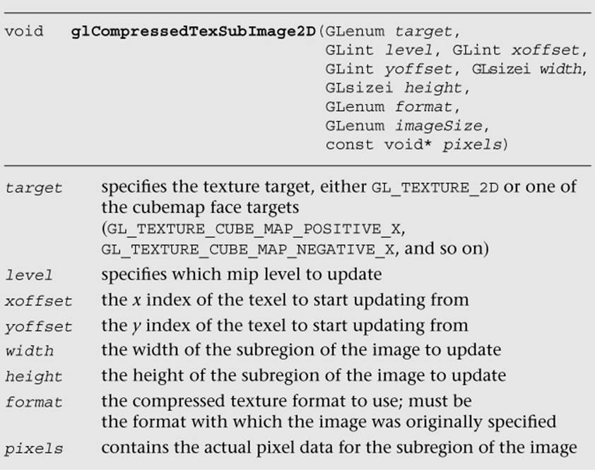
There is also a function for updating a subregion of a compressed 2D texture image—that is, glCompressedTexSubImage2D. The definition for this function is more or less the same as that for glTexImage2D.
In addition, as with 2D textures, it is possible to update just a subregion of an existing 3D texture and 2D texture arrays using glTexSubImage3D.
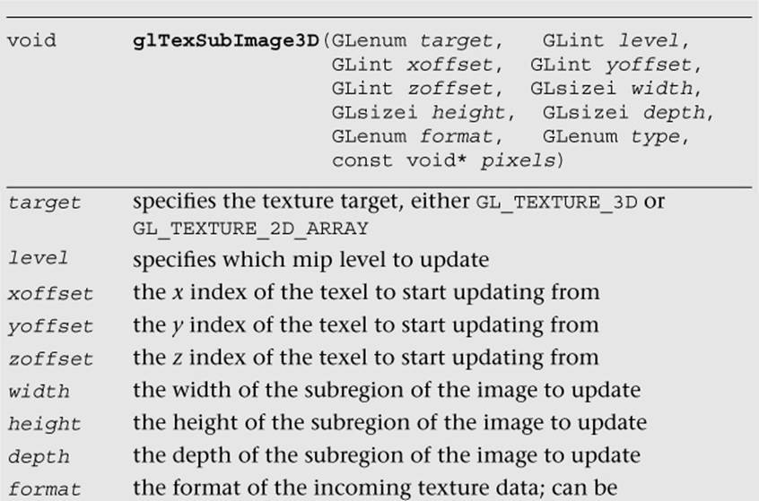
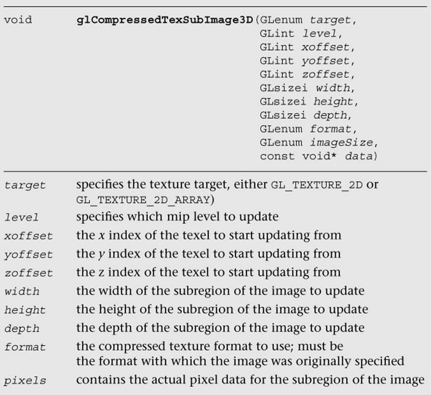
glTexSubImage3D behaves just like glTexSubImage2D, with the only difference being that the subregion contains a zoffset and a depth for specifying the subregion within the depth slices to update. For compressed 2D texture arrays, it is also possible to update a subregion of the texture using glCompressedTexSubImage3D. For 3D textures, this function can be used only with vendor-specific 3D compressed texture formats, because ETC2/EAC are supported only for 2D textures and 2D texture arrays.
Copying Texture Data from the Color Buffer
An additional texturing feature that is supported in OpenGL ES 3.0 is the ability to copy data from a color buffer to a texture. This can be useful if you want to use the results of rendering as an image in a texture. Framebuffer objects (Chapter 12) provide a fast method for doing render-to-texture and are a faster method than copying image data. However, if performance is not a concern, the ability to copy image data out of the color buffer can be a useful feature.
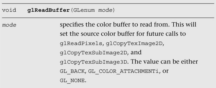
The color buffer from which to copy image data from can be set using the function glReadBuffer. If the application is rendering to a double-buffered EGL displayable surface, then glReadBuffer must be set to GL_BACK (the back buffer—the default state). Recall that OpenGL ES 3.0 supports only double-buffered EGL displayable surfaces. As a consequence, all OpenGL ES 3.0 applications that draw to the display will have a color buffer for both the front and back buffers. The buffer that is currently the front or back is determined by the most recent call toeglSwapBuffers (described in Chapter 3, “An Introduction to EGL”). When you copy image data out of the color buffer from a displayable EGL surface, you will always be copying the contents of the back buffer. If you are rendering to an EGL pbuffer, then copying will occur from the pbuffer surface. Finally, if you are rendering to a framebuffer object, then the framebuffer object color attachment to copy from is set by calling glReadBuffer with GL_COLOR_ATTACHMENTi.
The functions to copy data from the color buffer to a texture are glCopyTexImage2D, glCopyTexSubImage2D, and glCopyTexSubImage3D.
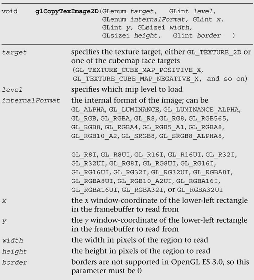
Calling this function will cause the texture image to be loaded with the pixels in the color buffer from region (x, y) to (x + width – 1, y + height – 1). This width and height of the texture image will be the size of the region copied from the color buffer. You should use this information to fill the entire contents of the texture.
In addition, you can update just the subregion of an already-specified image using glCopyTexSubImage2D.
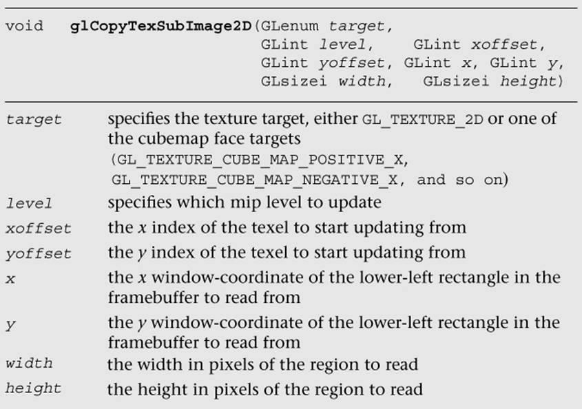
This function will update the subregion of the image starting at (xoffset, yoffset) to (xoffset + width – 1, yoffset + height – 1) with the pixels in the color buffer from (x, y) to (x + width – 1, y + height – 1).
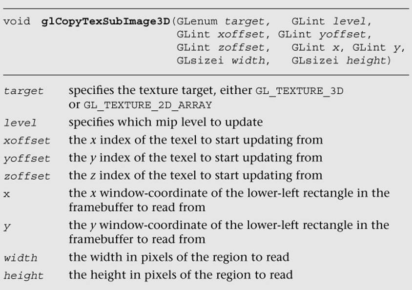
Finally, you can also copy the contents of the color buffer into a slice (or subregion of a slice) of a previously specified 3D texture or 2D texture array using glCopyTexSubImage3D.
One thing to keep in mind with glCopyTexImage2D, glCopyTexSubImage2D, and glCopyTexSubImage3D is that the texture image format cannot have more components than the color buffer. In other words, when copying data out of the color buffer, it is possible to convert to a format with fewer components, but not with more. Table 9-13 shows the valid format conversions when doing a texture copy. For example, you can copy an RGBA image into any of the possible formats, but you cannot copy an RGB into an RGBA image because no alpha component exists in the color buffer.
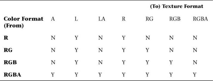
Table 9-13 Valid Format Conversions for glCopyTex*Image*
Sampler Objects
Previously in the chapter, we covered how to set texture parameters such as filter modes, texture coordinate wrap modes, and LOD settings using glTexParameter[i|f][v]. The issue with using glTexParameter[i|f][v] is that it can result in a significant amount of unnecessary API overhead. Very often, an application will use the same texture settings for a large number of textures. In such a case, having to set the sampler state with glTexParameter[i|f][v] for every texture object can result in a lot of extra overhead. To mitigate this problem, OpenGL ES 3.0 introduces sampler objects that separate sampler state from texture state. In short, all of the settings that can be set with glTexParameter[i|f][v] can be set for a sampler object and can be bound for use with a texture unit in a single function call. Sampler objects can be used across many textures and, therefore, reduce API overhead.
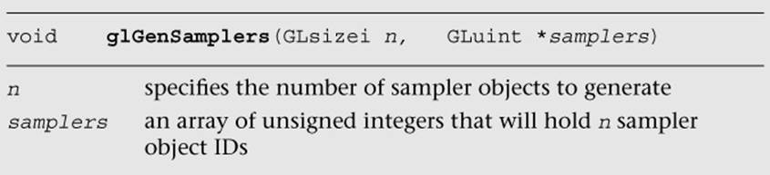
The function used to generate sampler objects is glGenSamplers.
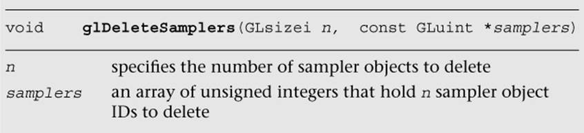
Sampler objects also need to be deleted when an application no longer needs them. This can be done using glDeleteSamplers.
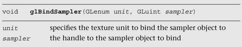
Once sampler object IDs have been generated with glGenSamplers, the application must bind the sampler object to use its state. Sampler objects are bound to texture units. Binding the sampler object to the texture unit supersedes any of the state set in the texture object usingglTexParameter[i|f][v]. The function used to bind a sampler object is glBindSampler.
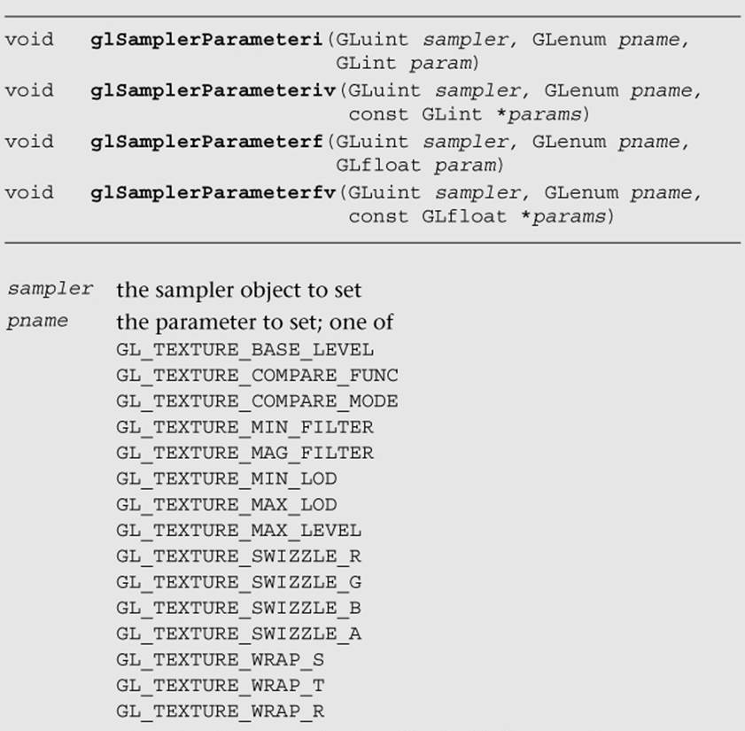
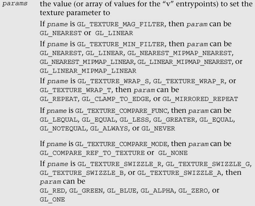
If the sampler passed to glBindSampler is 0 (the default sampler), then the state set for the texture object will be used. The sampler object state can be set using glSamplerParameter[f|i][v]. The parameters that can be set by glSamplerParameter[f|i][v] are the exact same ones that are set by using glTexParameter[i|f][v]. The only difference is that the state is set to the sampler object rather than the texture object.
Immutable Textures
Another feature introduced in OpenGL ES 3.0 to help improve application performance is immutable textures. As discussed earlier in this chapter, an application specifies each mipmap level of a texture independently using functions such as glTexImage2D and glTexImage3D. The problem this creates for the OpenGL ES driver is that it cannot determine until draw time whether a texture has been fully specified. That is, it has to check whether each mipmap level or subimage has matching formats, whether each level has the correct dimensions, and whether there is sufficient memory. This draw time check can be costly and can be avoided by using immutable textures.
The idea behind immutable textures is simple: The application specifies the format and size of a texture before loading it with data. In doing so, the texture format becomes immutable and the OpenGL ES driver can perform all consistency and memory checks up-front. Once a texture has become immutable, its format and dimensions cannot change. However, the application can still load it with image data by using glTexSubImage2D, glTexSubImage3D, or glGenerateMipMap, or by rendering to the texture.
To create an immutable texture, an application would bind the texture using glBindTexture and then allocate its immutable storage using glTexStorage2D or glTexStorage3D.
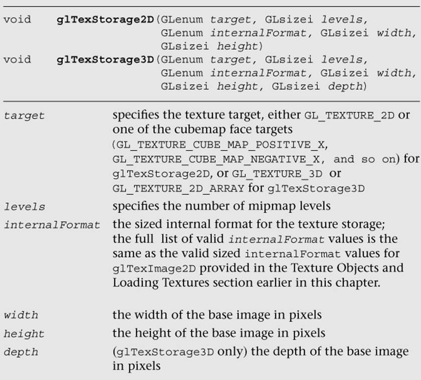
Once the immutable texture is created, it is invalid to call glTexImage*, glCompressedTexImage*, glCopyTexImage*, or glTexStorage* on the texture object. Doing so will result in a GL_INVALID_OPERATION error being generated. To fill the immutable texture with image data, the application needs to use glTexSubImage2D, glTexSubImage3D, or glGenerateMipMap, or else render to the image as a texture (by using it as an attachment to a framebuffer object).
Internally, when glTexStorage* is used, OpenGL ES marks the texture object as being immutable by setting GL_TEXTURE_IMMUTABLE_FORMAT to GL_TRUE and GL_TEXTURE_IMMUTABLE_LEVELS to the number of levels passed to glTexStorage*. The application can query for these values by using glGetTexParameter[i|f][v], although it cannot set them directly. The glTexStorage* function must be used to set up the immutable texture parameters.
Pixel Unpack Buffer Objects
In Chapter 6, “Vertex Attributes, Vertex Arrays, and Buffer Objects,” we introduced buffer objects, concentrating the discussion on vertex buffer objects (VBOs) and copy buffer objects. As you will recall, buffer objects allow the storage of data in server-side (or GPU) memory as opposed to client-side (or host) memory. The advantage of using buffer objects is that they reduce the transfer of data from CPU to GPU and, therefore, can improve performance (as well as reduce memory utilization). OpenGL ES 3.0 also introduces pixel unpack buffer objects that are bound and specified with the GL_PIXEL_UNPACK_BUFFER target. The functions that operate on pixel unpack buffer objects are described in Chapter 6. Pixel unpack buffer objects allow the specification of texture data that resides in server-side memory. As a consequence, the pixel unpack operationsglTexImage*, glTexSubImage*, glCompressedTexImage*, and glCompressedTexSubImage* can come directly from a buffer object. Much like VBOs with glVertexAttribPointer, if a pixel unpack buffer object is bound during one of those calls, the data pointer is an offset into the pixel unpack buffer rather than a pointer to client memory.
Pixel unpack buffer objects can be used to stream texture data to the GPU. The application could allocate a pixel unpack buffer and then map regions of the buffer for updates. When the calls to load the data to OpenGL are made (e.g., glTexSubImage*), these functions can return immediately because the data already resides in the GPU (or can be copied at a later time, but an immediate copy does not need to be made as it does with client-side data). We recommend using pixel unpack buffer objects in situations where the performance/memory utilization of texture upload operations is important for the application.
Summary
This chapter covered how to use textures in OpenGL ES 3.0. We introduced the various types of textures: 2D, 3D, cubemaps, and 2D texture arrays. For each texture type, we showed how the texture can be loaded with data either in full, in subimages, or by copying data from the framebuffer. We detailed the wide range of texture formats available in OpenGL ES 3.0, which include normalized texture formats, floating-point textures, integer textures, shared exponent textures, sRGB textures, and depth textures. We covered all of the texture parameters that can be set for texture objects, including filter modes, wrap modes, depth texture comparison, and level-of-detail settings. We explored how to set texture parameters using the more efficient sampler objects. Finally, we showed how to create immutable textures that can help reduce the draw-time overhead of using textures. We also saw how textures can be read in the fragment shader with several example programs. With all this information under your belt, you are well on your way toward using OpenGL ES 3.0 for many advanced rendering effects. Next, we cover more details of the fragment shader that will help you further understand how textures can be used to achieve a wide range of rendering techniques.
All materials on the site are licensed Creative Commons Attribution-Sharealike 3.0 Unported CC BY-SA 3.0 & GNU Free Documentation License (GFDL)
If you are the copyright holder of any material contained on our site and intend to remove it, please contact our site administrator for approval.
© 2016-2026 All site design rights belong to S.Y.A.