OpenGL ES 3.0: Programming Guide, Second Edition (2014)
Chapter 5. OpenGL ES Shading Language
As you saw in earlier chapters, shaders are a fundamental concept that lies at the heart of the OpenGL ES 3.0 API. Every OpenGL ES 3.0 program requires both a vertex shader and a fragment shader to render a meaningful picture. Given the centrality of the concept of shaders to the API, we want to make sure you are grounded in the fundamentals of writing shaders before diving into more details of the graphics API.
This chapter’s goal is to make sure you understand the following concepts in the shading language:
• Variables and variable types
• Vector and matrix construction and selection
• Constants
• Structures and arrays
• Operators, control flow, and functions
• Input/output variables, uniforms, uniform blocks, and layout qualifiers
• Preprocessor and directives
• Uniform and interpolator packing
• Precision qualifiers and invariance
You were introduced to some of these concepts in a small amount of detail with the example in Chapter 2, “Hello Triangle: An OpenGL ES 3.0 Example.” Now we will fill in the concepts with a lot more detail to make sure you understand how to write and read shaders.
OpenGL ES Shading Language Basics
As you read through this book, you will look at a lot of shaders. If you ever start developing your own OpenGL ES 3.0 application, chances are that you will write a lot of shaders. By now, you should understand the fundamental concepts of what a shader does and how it fits in the pipeline. If not, please go back and review Chapter 1, “Introduction to OpenGL ES 3.0,” where we covered the pipeline and described where vertex and fragment shaders fit within it.
What we want to look at now is what exactly makes up a shader. As you have probably already observed, the syntax bears great similarity to that seen in the C programming language. If you can understand C code, you likely will not have much difficulty understanding the syntax of shaders. However, there are certainly some major differences between the two languages, beginning with the version specification and the native data types that are supported.
Shader Version Specification
The first line of your OpenGL ES 3.0 vertex and fragment shaders will always declare a shader version. Declaring the shader version informs the shader compiler which syntax and constructs it can expect to be present in the shader. The compiler checks the shader syntax against the declared version of the shading language used. To declare that your shader uses version 3.00 of the OpenGL ES Shading Language, use the following syntax:
#version 300 es
Shaders that do not declare a version number are assumed to use revision 1.00 of the OpenGL ES Shading Language. Revision 1.00 of the shading language is the version that was used in OpenGL ES 2.0. For OpenGL ES 3.0, the specification authors decided to match the version numbers for the API and Shading Language, which explains why the number jumped from 1.00 to 3.00 for OpenGL ES 3.0. As described in Chapter 1, “Introduction to OpenGL ES 3.0,” the OpenGL ES Shading Language 3.0 adds many new features, including non-square matrices, full integer support, interpolation qualifiers, uniform blocks, layout qualifiers, new built-in functions, full looping, full branching support, and unlimited shader instruction length.
Variables and Variable Types
In computer graphics, two fundamental data types form the basis of transformations: vectors and matrices. These two data types are central to the OpenGL ES Shading Language as well. Specifically, Table 5-1 describes the scalar-, vector-, and matrix-based data types that exist in the shading language.
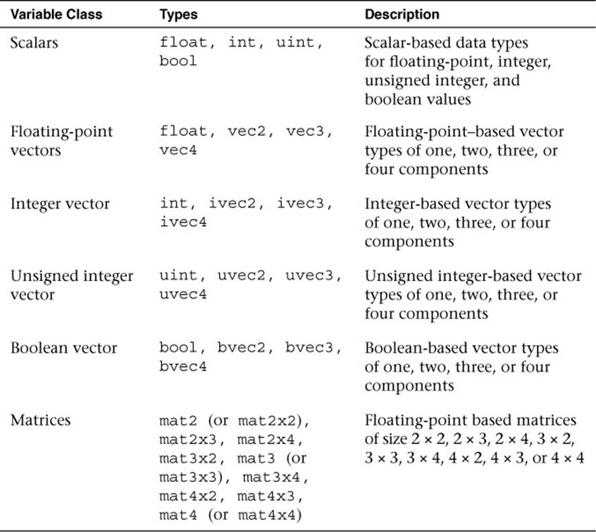
Table 5-1 Data Types in the OpenGL ES Shading Language
Variables in the shading language must be declared with a type. For example, the following declarations illustrate how to declare a scalar, a vector, and a matrix:
float specularAtten; // A floating-point-based scalar
vec4 vPosition; // A floating-point-based 4-tuple vector
mat4 mViewProjection; // A 4 x 4 matrix variable declaration
ivec2 vOffset; // An integer-based 2-tuple vector
Variables can be initialized either at declaration time or later. Initialization is done through the use of constructors, which are also used for doing type conversions.
Variable Constructors
The OpenGL ES Shading Language has very strict rules regarding type conversion. That is, variables can only be assigned to or operated on other variables of the same type. The reasoning behind not allowing implicit type conversion in the language is that it avoids shader authors encountering unintended conversion that can lead to difficult-to-track-down bugs. To cope with type conversions, a number of constructors are available in the language. You can use constructors for initializing variables and as a way of type-casting between variables of different types. Variables can be initialized at declaration (or later in the shader) through the use of constructors. Each of the built-in variable types has a set of associated constructors.
Let’s first look at how constructors can be used to initialize and type-cast between scalar values.
float myFloat = 1.0;
float myFloat2 = 1; // ERROR: invalid type conversion
bool myBool = true;
int myInt = 0;
int myInt2 = 0.0; // ERROR: invalid type conversion
myFloat = float(myBool); // Convert from bool -> float
myFloat = float(myInt); // Convert from int -> float
myBool = bool(myInt); // Convert from int -> bool
Similarly, constructors can be used to convert to and initialize vector data types. The arguments to a vector constructor will be converted to the same basic type as the vector being constructed (float, int, or bool). There are two basic ways to pass arguments to vector constructors:
• If only one scalar argument is provided to a vector constructor, that value is used to set all values of the vector.
• If multiple scalar or vector arguments are provided, the values of the vector are set from left to right using those arguments. If multiple scalar arguments are provided, there must be at least as many components in the arguments as in the vector.
The following shows some examples of constructing vectors:
vec4 myVec4 = vec4(1.0); // myVec4 = {1.0, 1.0, 1.0,
// 1.0}
vec3 myVec3 = vec3(1.0,0.0,0.5); // myVec3 = {1.0, 0.0, 0.5}
vec3 temp = vec3(myVec3); // temp = myVec3
vec2 myVec2 = vec2(myVec3); // myVec2 = {myVec3.x,
// myVec3.y}
myVec4 = vec4(myVec2, temp); // myVec4 = {myVec2.x,
// myVec2.y,
// temp.x, temp.y}
For matrix construction, the language is flexible. These basic rules describe how matrices can be constructed:
• If only one scalar argument is provided to a matrix constructor, that value is placed in the diagonal of the matrix. For example, mat4 (1.0) will create a 4 × 4 identity matrix.
• A matrix can be constructed from multiple vector arguments. For example, a mat2 can be constructed from two vec2s.
• A matrix can be constructed from multiple scalar arguments—one for each value in the matrix, consumed from left to right.
The matrix construction is even more flexible than the basic rules just stated, in that a matrix can basically be constructed from any combination of scalars and vectors as long as enough components are provided to initialize the matrix. Matrices in OpenGL ES are stored in column major order. When using a matrix constructor, the arguments will be consumed to fill the matrix by column. The comments in the following example show how the matrix constructor arguments map into columns.
mat3 myMat3 = mat3(1.0, 0.0, 0.0, // First column
0.0, 1.0, 0.0, // Second column
0.0, 1.0, 1.0); // Third column
Vector and Matrix Components
The individual components of a vector can be accessed in two ways: by using the “.” operator or through array subscripting. Depending on the number of components that make up a given vector, each of the components can be accessed through the use of the swizzles {x, y, z, w}, {r, g, b, a}, or {s, t, p, q}. The reason for the three different naming schemes is that vectors are used interchangeably to represent mathematical vectors, colors, and texture coordinates. The x, r, or s component will always refer to the first element of a vector. The different naming conventions are just provided as a convenience. That said, you cannot mix naming conventions when accessing a vector (in other words, you cannot do something like .xgr, as you can use only one naming convention at a time). When using the “.” operator, it is also possible to reorder components of a vector in an operation. The following examples show how this can be done.
vec3 myVec3 = vec3(0.0, 1.0, 2.0); // myVec3 = {0.0, 1.0, 2.0}
vec3 temp;
temp = myVec3.xyz; // temp = {0.0, 1.0, 2.0}
temp = myVec3.xxx; // temp = {0.0, 0.0, 0.0}
temp = myVec3.zyx; // temp = {2.0, 1.0, 0.0}
In addition to the “.” operator, vectors can be accessed using the array subscript “[]” operator. In array subscripting, element [0] corresponds to x, element [1] corresponds to y, and so forth. Matrices are treated as being composed of a number of vectors. For example, a mat2 can be thought of as two vec2s, a mat3 as three vec3s, and so forth. For matrices, the individual column is selected using the array subscript operator “[]”, and then each vector can be accessed using the vector access behavior. The following shows some examples of accessing matrices:
mat4 myMat4 = mat4(1.0); // Initialize diagonal to 1.0
(identity)
vec4 colO = myMat4[0]; // Get colO vector out of the matrix
float ml_l = myMat4[1][1]; // Get element at [1][1] in matrix
float m2_2 = myMat4[2].z; // Get element at [2][2] in matrix
Constants
It is possible to declare any of the basic types as being constant variables. Constant variables are those whose values do not change within the shader. To declare a constant, you add the const qualifier to the declaration. Constant variables must be initialized at declaration time. Some examples of const declarations follow:
const float zero = 0.0;
const float pi = 3.14159;
const vec4 red = vec4(1.0, 0.0, 0.0, 1.0);
const mat4 identity = mat4(1.0);
Just as in C or C++, a variable that is declared as const is read-only and cannot be modified within the source.
Structures
In addition to using the basic types provided in the language, it is possible to aggregate variables into structures much like in C. The declaration syntax for a structure in the OpenGL ES Shading Language is shown in the following example:
struct fogStruct
{
vec4 color;
float start;
float end;
} fogVar;
The preceding definition will result in a new user type named fogStruct and a new variable named fogVar.
Structures can be initialized using constructors. After a new structure type is defined, a new structure constructor is also defined with the same name as the type. There must be a one-to-one correspondence between types in the structure and those in the constructor. For example, the preceding structure could be initialized using the following construction syntax:
struct fogStruct
{
vec4 color;
float start;
float end;
} fogVar;
fogVar = fogStruct(vec4(0.0, 1.0, 0.0, 0.0), // color
0.5, // start
2.0); // end
The constructor for the structure is based on the name of the type and takes as arguments each of the components. Accessing the elements of a structure is done just as you would with a structure in C, as shown in the following example:
vec4 color = fogVar.color;
float start = fogVar.start;
float end = fogVar.end;
Arrays
In addition to structures, the OpenGL ES Shading Language supports arrays. The syntax is very similar to C, with the arrays being based on a 0 index. The following block of code shows some examples of creating arrays:
float floatArray[4];
vec4 vecArray[2];
Arrays can be initialized using the array initializer constructor, as shown in the following code:
float a[4] = float[](1.0, 2.0, 3.0, 4.0);
float b[4] = float[4](1.0, 2.0, 3.0, 4.0);
vec2 c[2] = vec2[2](vec2(1.0), vec2(1.0));
Providing a size to the array constructor is optional. The number of arguments in the array constructor must be equal to the size of the array.
Operators
Table 5-2 lists the operators that are offered in the OpenGL ES Shading Language.
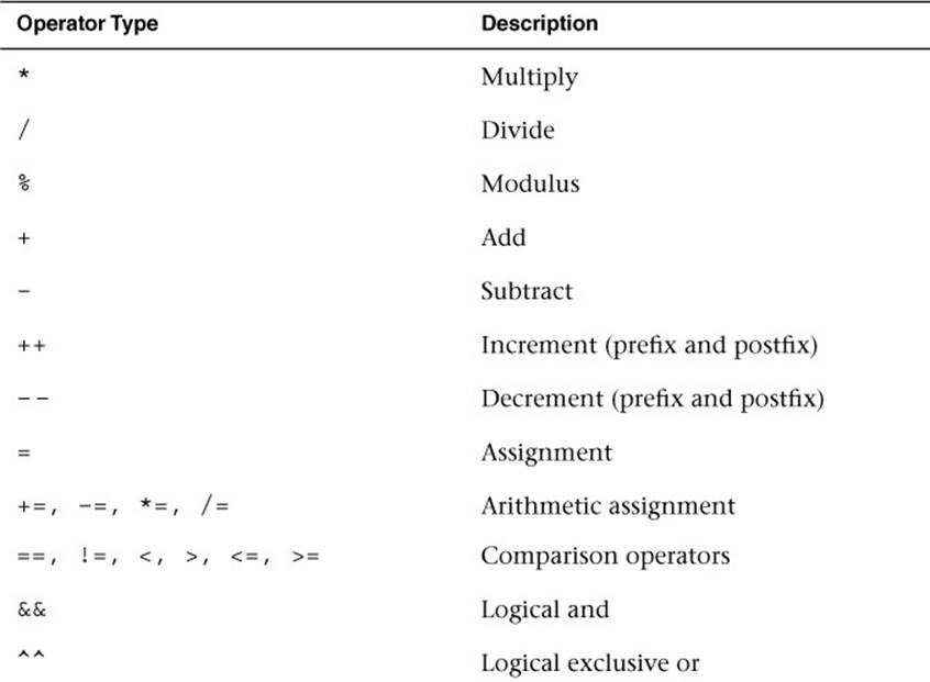
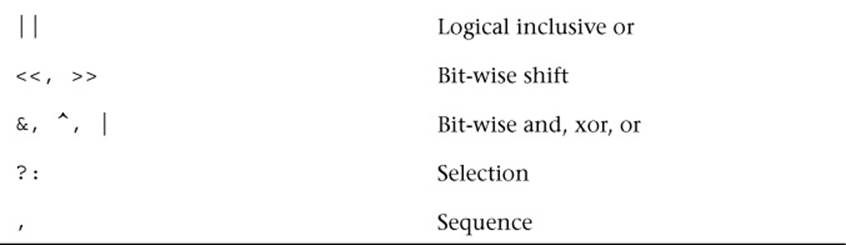
Table 5-2 OpenGL ES Shading Language Operators
Most of these operators behave just as they do in C. As mentioned in the constructor section, the OpenGL ES Shading Language has strict type rules that govern operators. That is, the operators must occur between variables that have the same basic type. For the binary operators (*, /, +, –), the basic types of the variables must be floating point or integer. Furthermore, operators such as multiply can operate between combinations of floats, vectors, and matrices. Some examples are provided here:
float myFloat;
vec4 myVec4;
mat4 myMat4;
myVec4 = myVec4 * myFloat; // Multiplies each component of
// myVec4 by a scalar myFloat
myVec4 = myVec4 * myVec4; // Multiplies each component of
// myVec4 together (e.g.,
// myVec4 ^ 2)
myVec4 = myMat4 * myVec4; // Does a matrix * vector multiply of
// myMat4 * myVec4
myMat4 = myMat4 * myMat4; // Does a matrix * matrix multiply of
// myMat4 * myMat4
myMat4 = myMat4 * myFloat; // Multiplies each matrix component
// by the scalar myFloat
The comparison operators, aside from == and != (<, <=, >, >=), can be used only with scalar values. To compare vectors, special built-in functions allow you to perform comparisons on a component-by-component basis (more on that later).
Functions
Functions are declared in much the same way as in C. If a function will be used prior to its definition, then a prototype declaration must be provided. The most significant difference between functions in the OpenGL ES Shading Language and C is the way in which parameters are passed to functions. The OpenGL ES Shading Language provides special qualifiers to define whether a variable argument can be modified by the function; these qualifiers are shown in Table 5-3.
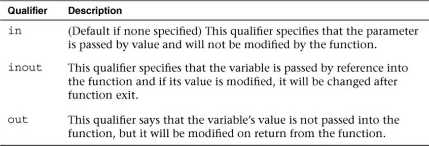
Table 5-3 OpenGL ES Shading Language Qualifiers
An example function declaration is provided here. This example shows the use of parameter qualifiers.
vec4 myFunc(inout float myFloat, // inout parameter
out vec4 myVec4, // out parameter
mat4 myMat4); // in parameter (default)
An example function definition is given here for a simple function that computes basic diffuse lighting:
vec4 diffuse(vec3 normal,
vec3 light,
vec4 baseColor)
{
return baseColor * dot(normal, light);
}
One note about functions in the OpenGL ES Shading Language: functions cannot be recursive. The reason for this limitation is that some implementations will implement function calls by actually placing the function code inline in the final generated program for the GPU. The shading language was purposely structured to allow this sort of inline implementation to support GPUs that do not have a stack.
Built-In Functions
The preceding section described how a shader author creates a function. One of the most powerful features of the OpenGL ES Shading Language is the built-in functions that are provided in the language. As an example, here is some shader code for computing basic specular lighting in a fragment shader:
float nDotL = dot(normal, light);
float rDotV = dot(viewDir, (2.0 * normal) * nDotL - light);
float specular = specularColor * pow(rDotV, specularPower);
As you can see, this block of shader code uses the dot built-in function to compute the dot product of two vectors and the pow built-in function to raise a scalar to a power. These are just two simple examples; a wide array of built-in functions are available in the OpenGL ES Shading Language to handle the various computational tasks that one typically has to do in a shader. Appendix B of this text provides a complete reference to the built-in functions provided in the OpenGL ES Shading Language. For now, we just want to make you aware that there are a lot of built-in functions in the language. To become proficient in writing shaders, you will need to familiarize yourself with the most common ones.
Control Flow Statements
The syntax for control flow statements in the OpenGL ES Shading Language is similar to that used in C. Simple if-then-else logical tests can be done using the same syntax as C. For example:
if(color.a < 0.25)
{
color *= color.a;
}
else
{
color = vec4(0.0);
}
The expression that is being tested in the conditional statement must evaluate to a boolean value. That is, the test must be based on either a boolean value or some expression that evaluates to a boolean value (e.g., a comparison operator). This is the basic concept underlying how conditionals are expressed in the OpenGL ES Shading Language.
In addition to basic if-then-else statements, it is possible to write for, while, and do-while loops. In OpenGL ES 2.0, very strict rules governed the usage of loops. Essentially, only loops that could be unrolled by the compiler were supported. These restrictions no longer exist in OpenGL ES 3.0. The GPU hardware is expected to provide support for looping and flow control; thus loops are fully supported.
That is not to say that loops don’t come with some performance implications. On most GPU architectures, vertices or fragments are executed in parallel in batches. The GPU typically requires that all fragments or vertices in a batch evaluate all branches (or loop iterations) of flow control statements. If vertices or fragments in a batch execute different paths, then, usually all of the other vertices/fragments in a batch will need to execute that path as well. The size of a batch is GPU dependent and will often require profiling to determine the performance implications of the use of flow control on a particular architecture. However, a good rule of thumb is to try to limit the use of divergent flow control or loop iterations across vertices/fragments.
Uniforms
One of the variable type modifiers in the OpenGL ES Shading Language is the uniform variable. Uniform variables store read-only values that are passed in by the application through the OpenGL ES 3.0 API to the shader. Uniforms are useful for storing all kinds of data that shaders need, such as transformation matrices, light parameters, and colors. Basically, any parameter to a shader that is constant across either all vertices or fragments should be passed in as a uniform. Variables whose value is known at compile-time should be constants rather than uniforms for efficiency.
Uniform variables are declared at the global scope and simply require the uniform qualifier. Some examples of uniform variables are shown here:
uniform mat4 viewProjMatrix;
uniform mat4 viewMatrix;
uniform vec3 lightPosition;
In Chapter 4, “Shaders and Programs,” we described how an application loads uniform variables to a shader. Note also that the namespace for uniform variables is shared across both a vertex shader and a fragment shader. That is, if vertex and fragment shaders are linked together into aprogram object, they share the same set of uniform variables. Therefore, if a uniform variable is declared in the vertex shader and also in the fragment shader, both of those declarations must match. When the application loads the uniform variable through the API, its value will be available in both the vertex and fragment shaders.
Uniform variables generally are stored in hardware into what is known as the “constant store.” This special space is allocated in the hardware for the storage of constant values. Because it is typically of a fixed size, the number of uniforms that can be used in a program is limited. This limitation can be determined by reading the value of the gl_MaxVertexUniformVectors and gl_MaxFragmentUniformVectors built-in variables (or by querying GL_MAX_VERTEX_UNIFORM_VECTORS or GL_MAX_FRAGMENT_UNIFORM_VECTORS usingglGetintegerv). An implementation of OpenGL ES 3.0 must provide at least 256 vertex uniform vectors and 224 fragment uniform vectors, although it is free to provide more. We cover the full set of limitations and queries available for the vertex and fragment shaders in Chapter 8, “Vertex Shaders,” and Chapter 10, “Fragment Shaders.”
Uniform Blocks
In Chapter 4, “Shaders and Programs,” we introduced the concept of uniform buffer objects. To review, uniform buffer objects allow the storage of uniform data to be backed by a buffer object. Uniform buffer objects offer several advantages over individual uniform variables in certain situations. For example, with uniform buffer objects, uniform buffer data can be shared across multiple programs but need to be set only once. Further, uniform buffer objects typically allow for storage of larger amounts of uniform data. Finally, it can be more efficient to switch between uniform buffer objects than to individually load one uniform at a time.
Uniform buffer objects can be used in the OpenGL ES Shading Language through application of uniform blocks. An example uniform block follows:
uniform TransformBlock
{
mat4 matViewProj;
mat3 matNormal;
mat3 matTexGen;
};
This code declares a uniform block with the name TransformBlock containing three matrices. The name TransformBlock will be used by the application as the blockName parameter to glGetUniformBlockIndex as described in Chapter 4, “Shaders and Programs,” for uniform buffer objects. The variables in the uniform block declaration are then accessed throughout the shader just as if they were declared as a regular uniform. For example, the matViewProj matrix declared in TransformBlock would be accessed as follows:
#version 300 es
uniform TransformBlock
{
mat4 matViewProj;
mat3 matNormal;
mat3 matTexGen;
};
layout(location = 0) in vec4 a_position;
void main()
{
gl_Position = matViewProj * a_position;
}
A number of optional layout qualifiers can be used to specify how the uniform buffer object that backs the uniform block will be laid out in memory. Layout qualifiers can be provided either for individual uniform blocks or globally for all uniform blocks. At the global scope, setting the default layout for all uniform blocks would look as follows:
layout(shared, column_major) uniform; // default if not
// specified
layout(packed, row_major) uniform;
Individual uniform blocks can also set the layout by overriding the default set at the global scope. In addition, individual uniforms within a uniform block can specify a layout qualifier as shown here:
layout(std140) uniform TransformBlock
{
mat4 matViewProj;
layout(row_major) mat3 matNormal;
mat3 matTexGen;
};
Table 5-4 lists all of the layout qualifiers that can be provided for uniform blocks.
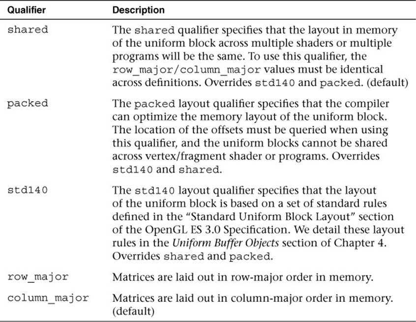
Table 5-4 Uniform Block Layout Qualifiers
Vertex and Fragment Shader Inputs/Outputs
Another special variable type in the OpenGL ES Shading Language is the vertex input (or attribute) variable. Vertex input variables are used to specify the per-vertex inputs to the vertex shader and are specified with the in keyword. They typically store data such as positions, normals, texture coordinates, and colors. The key here to understand is that vertex inputs are data that are specified for each vertex being drawn. Example 5-1 is a sample vertex shader that has a position and color vertex input.
The two vertex inputs in this shader, a_position and a_color, will be loaded with data by the application. Essentially, the application will create a vertex array that contains a position and a color for each vertex. Notice that the vertex inputs in Example 5-1 are preceded by the layoutqualifier. The layout qualifier in this case is used to specify the index of the vertex attribute. The layout qualifier is optional; if it is not specified, the linker will automatically assign locations for the vertex inputs. We explain this entire process in full detail in Chapter 6, “Vertex Attributes, Vertex Arrays, and Buffer Objects.”
Example 5-1 Sample Vertex Shader
#version 300 es
uniform mat4 u_matViewProjection;
layout(location = 0) in vec4 a_position;
layout(location = 1) in vec3 a_color;
out vec3 v_color;
void main(void)
{
gl_Position = u_matViewProjection * a_position;
v_color = a_color;
}
As with uniform variables, the underlying hardware typically places limits on the number of attribute variables that can be input to a vertex shader. The maximum number of attributes that an implementation supports is given by the gl_MaxVertexAttribs built-in variable (it can also be found by querying for GL_MAX_VERTEX_ATTRIBS using glGetIntegerv). The minimum number of attributes that an OpenGL ES 3.0 implementation can support is 16. Implementations are free to support more, but if you want to write shaders that are guaranteed to run on any OpenGL ES 3.0 implementation, you should restrict yourself to using no more than 16 attributes. We cover attribute limitations in more detail in Chapter 8, “Vertex Shaders.”
The output variables from the vertex shader are specified with the out keyword. In Example 5-1, the v_color variable is declared as an output and its contents are copied from the a_color input variable. Each vertex shader will output the data it needs to pass the fragment shader into one or more output variables. These variables will then also be declared in the fragment shader as in variables (with matching types) and will be linearly interpolated across the primitive during rasterization (if you want more details on how this interpolation occurs during rasterization, jump toChapter 7, “Primitive Assembly and Rasterization”).
For example, the matching input declaration in the fragment shader for the v_color vertex output in Example 5-1 follows:
in vec3 v_color;
Note that unlike the vertex shader input, the vertex shader output/fragment shader input variables cannot have layout qualifiers. The implementation automatically chooses locations. As with uniforms and vertex input attributes, the underlying hardware typically limits the number of vertex shader outputs/fragment shader inputs (on the hardware, these are usually referred to as interpolators). The number of vertex shader outputs supported by an implementation is given by the gl_MaxVertexOutputVectors built-in variable (querying forGL_MAX_VERTEX_OUTPUT_COMPONENTS using glGetIntegerv will provide the number of total component values rather than the number of vectors). The minimum number of vertex output vectors that an implementation of OpenGL ES 3.0 can support is 16. Likewise, the number of fragment shader inputs supported by an implementation is given by gl_MaxFragmentInputVectors (querying for GL_MAX_FRAGMENT_INPUT_COMPONENTS using glGetIntegerv will provide the number of total component values rather than the number of vectors). The minimum number of fragment input vectors that an implementation of OpenGL ES 3.0 can support is 15.
Example 5-2 is an example of a vertex shader and a fragment shader with matching output/input declarations.
Example 5-2 Vertex and Fragment Shaders with Matching Output/Input Declarations
// Vertex shader
#version 300 es
uniform mat4 u_matViewProjection;
// Vertex shader inputs
layout(location = 0) in vec4 a_position;
layout(location = 1) in vec3 a_color;
// Vertex shader output
out vec3 v_color;
void main(void)
{
gl_Position = u_matViewProjection * a_position;
v_color = a_color;
}
// Fragment shader
#version 300 es
precision mediump float;
// Input from vertex shader
in vec3 v_color;
// Output of fragment shader
layout(location = 0) out vec4 o_fragColor;
void main()
{
o_fragColor = vec4(v_color, 1.0);
}
In Example 5-2, the fragment shader contains the definition for the output variable o_fragColor:
layout(location = 0) out vec4 o_fragColor;
The fragment shader can output one or more colors. In the typical case, we will render just to a single color buffer, in which case the layout qualifier is optional (the output variable is assumed to go to location 0). However, when rendering to multiple render targets (MRTs), we can use the layout qualifier to specify which render target each output goes to. MRTs are covered in detail in Chapter 11, “Fragment Operations.” For the typical case, you will have one output variable in your fragment shader, and that value will be the output color that is passed to the per-fragment operations portions of the pipeline.
Interpolation Qualifiers
In Example 5-2, we declared our vertex shader output and fragment shader input without any qualifiers. The default behavior for interpolation when no qualifiers are present is to perform smooth shading. That is, the output variables from the vertex shader are linearly interpolated across the primitive, and the fragment shader receives that linearly interpolated value as its input. We could have explicitly requested smooth shading rather than relying on the default behavior in Example 5-2, in which case our output/inputs would be as follows:
// ...Vertex shader...
// Vertex shader output
smooth out vec3 v_color;
// ...Fragment shader...
// Input from vertex shader
smooth in vec3 v_color;
OpenGL ES 3.0 also introduces another type of interpolation known as flat shading. In flat shading, the value is not interpolated across the primitive. Rather, one of the vertices is considered the provoking vertex (dependent on the primitive type; we describe this in the Chapter 7 section,Provoking Vertex), and that vertex value is used for all fragments in the primitive. We can declare the output/inputs as flat shaded as follows:
// ...Vertex shader...
// Vertex shader output
flat out vec3 v_color;
// ...Fragment shader...
// Input from vertex shader
flat in vec3 v_color;
Finally, another qualifier can be added to interpolators with the centroid keyword. The definition of centroid sampling is provided in Chapter 11 in the section Multisampled Anti-Aliasing. Essentially, when rendering with multisampling, the centroid keyword can be used to force interpolation to occur inside the primitive being rendered (otherwise, artifacts can occur at the edges of primitives). See Chapter 11, “Fragment Operations,” for a full definition of centroid sampling. For now, we simply show how you can declare an output/input variable with centroid sampling:
// ...Vertex shader...
// Vertex shader output
smooth centroid out vec3 v_color;
// ...Fragment shader...
// Input from vertex shader
smooth centroid in vec3 v_color;
Preprocessor and Directives
One feature of the OpenGL ES Shading Language we have not mentioned yet is the preprocessor. The OpenGL ES Shading Language features a preprocessor that follows many of the conventions of a standard C++ preprocessor. Macros can be defined and conditional tests can be performed using the following directives:
#define
#undef
#if
#ifdef
#ifndef
#else
#elif
#endif
Note that macros cannot be defined with parameters (as they can be in C++ macros). The #if, #else, and #elif directives can use the defined test to see whether a macro is defined. The following macros are predefined and their description is given next:
__LINE__ // Replaced with the current line number in a shader
__FILE__ // Always 0 in OpenGL ES 3.0
__VERSION__ // The OpenGL ES shading language version
// (e.g., 300)
GL_ES // This will be defined for ES shaders to a value
// of 1
The #error directive will cause a compilation error to occur during shader compilation, with a corresponding message being placed in the info log. The #pragma directive is used to specify implementation-specific directives to the compiler.
Another important directive in the preprocessor is #extension, which is used to enable and set the behavior of extensions. When vendors (or groups of vendors) extend the OpenGL ES Shading Language, they will create a language extension specification (e.g.,GL_NV_shadow_samplers_cube). The shader must instruct the compiler as to whether to allow extensions to be used, and if not, which behavior should occur. This is done using the #extension directive. The general format of #extension usage is shown in the following code:
// Set behavior for an extension
#extension extension_name : behavior
// Set behavior for ALL extensions
#extension all : behavior
The first argument will be either the name of the extension (e.g., GL_NV_shadow_samplers_cube) or all, which means that the behavior applies to all extensions. The behavior has four possible options, as shown in Table 5-5.
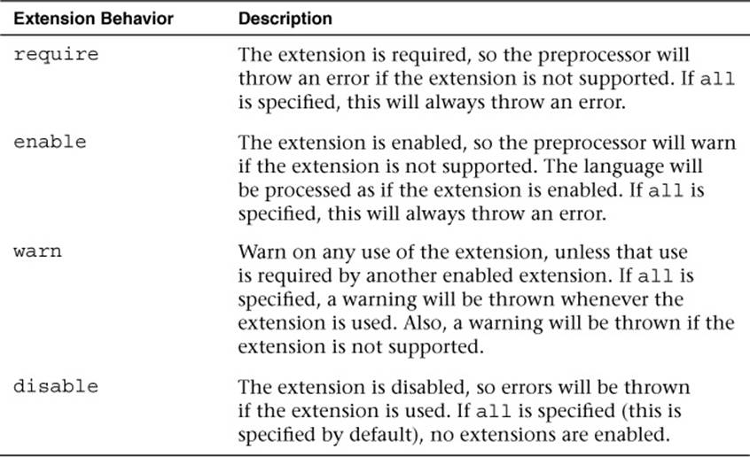
Table 5-5 Extension Behaviors
As an example, suppose you want the preprocessor to produce a warning if the NVIDIA shadow samplers cube extension is not supported (and you want the shader to be processed as if it is supported). To do so, you would add the following at the top of your shader:
#extension GL_NV_shadow_samplers_cube : enable
Uniform and Interpolator Packing
As noted in the preceding sections on uniforms and vertex shader outputs/fragment shader inputs, a fixed number of underlying hardware resources are available for the storage of each variable. Uniforms are typically stored in the so-called constant store, which can be thought of as a physical array of vectors. Vertex shader outputs/fragment shader inputs are typically stored in interpolators, which again are usually stored as an array of vectors. As you have probably noticed, shaders can declare uniforms and shader input/outputs of various types, including scalars, various vector components, and matrices. But how do these variable declarations map to the physical space that’s available on the hardware? In other words, if an OpenGL ES 3.0 implementation says it supports 16 vertex shader output vectors, how does the physical storage actually get used?
In OpenGL ES 3.0, this issue is handled through packing rules that define how the interpolators and uniforms will map to physical storage space. The rules for packing are based on the notion that the physical storage space is organized into a grid with four columns (one column for each vector component) and a row for each storage location. The packing rules seek to pack variables such that the complexity of the generated code remains constant. In other words, the packing rules will not do reordering that requires the compiler to generate extra instructions to merge unpacked data. Rather, the packing rules seek to optimize the use of the physical address space without negatively impacting runtime performance.
Let’s look at an example group of uniform declarations and see how these would be packed:
uniform mat3 m;
uniform float f[6];
uniform vec3 v;
If no packing were done at all, you can see that a lot of constant storage space would be wasted. The matrix m would take up three rows, the array f would take up six rows, and the vector v would take up one row. This would use a total of 10 rows to store the variables. Table 5-6 shows what the results would be without any packing. With the packing rules, the variables will get organized such that they pack into the grid as shown in Table 5-7.
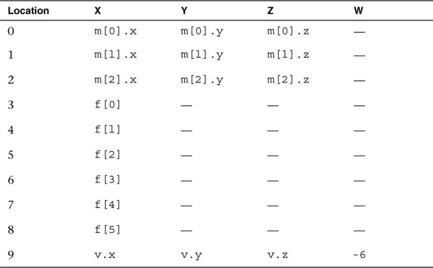
Table 5-6 Uniform Storage without Packing
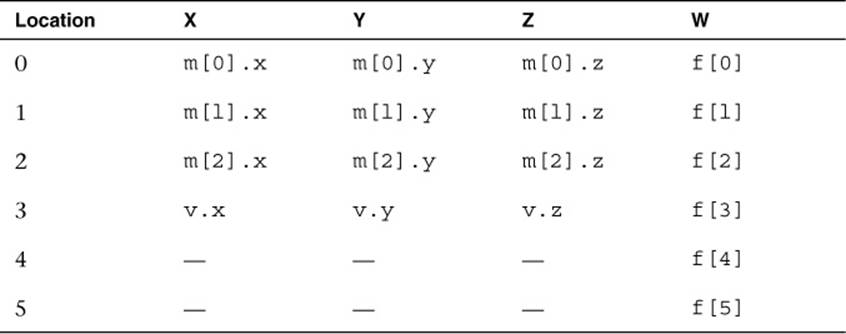
Table 5-7 Uniform Storage with Packing
With the packing rules, only six physical constant locations need to be used. You will notice that the array f needs to keep its elements spanning across row boundaries. The reason for this is that typically GPUs index the constant store by vector location index. The packing must keep the arrays spanning across row boundaries so that indexing will still work.
All of the packing that is done is completely transparent to the user of the OpenGL ES Shading Language, except for one detail: The packing impacts the way in which uniforms and vertex shader outputs/fragment shader inputs are counted. If you want to write shaders that are guaranteed to run on all implementations of OpenGL ES 3.0, you should not use more uniforms or interpolators than would exceed the minimum allowed storage sizes after packing. For this reason, it’s important to be aware of packing so that you can write portable shaders that will not exceed the minimum allowed storage on any implementation of OpenGL ES 3.0.
Precision Qualifiers
Precision qualifiers enable the shader author to specify the precision with which computations for a shader variable are performed. Variables can be declared to have either low, medium, or high precision. These qualifiers are used as hints to the compiler to allow it to perform computations with variables at a potentially lower range and precision. It is possible that at lower precisions, some implementations of OpenGL ES might be able to run the shaders either faster or with better power efficiency. Of course, that efficiency savings comes at the cost of precision, which can result in artifacts if precision qualifiers are not used properly. Note that nothing in the OpenGL ES specification says that multiple precisions must be supported in the underlying hardware, so it is perfectly valid for an implementation of OpenGL ES to perform all calculations at the highest precision and simply ignore the qualifiers. However, on some implementations, using a lower precision might offer an advantage.
Precision qualifiers can be used to specify the precision of any floating-point or integer-based variable. The keywords for specifying the precision are lowp, mediump, and highp. Some examples of declarations with precision qualifiers are shown here:
highp vec4 position;
varying lowp vec4 color;
mediump float specularExp;
In addition to precision qualifiers, the notion of default precision is available. That is, if a variable is declared without having a precision qualifier, it will have the default precision for that type. The default precision qualifier is specified at the top of a vertex or fragment shader using the following syntax:
precision highp float;
precision mediump int;
The precision specified for float will be used as the default precision for all variables based on a floating-point value. Likewise, the precision specified for int will be used as the default precision for all integer-based variables.
In the vertex shader, if no default precision is specified, then the default precision for both int and float is highp. That is, all variables declared without a precision qualifier in a vertex shader will have the highest precision. The rules for the fragment shader are different. In the fragment shader, there is no default precision given for floating-point values: Every shader must declare a default float precision or specify the precision for every float variable.
One final note is that the precision specified by a precision qualifier has an implementation-dependent range and precision. There is an associated API call for determining the range and precision for a given implementation, which is covered in Chapter 15, “State Queries.” As an example, on the PowerVR SGX GPU, a lowp float variable is represented in a 10-bit fixed point format, a mediump float variable is a 16-bit floating-point value, and a highp float is a 32-bit floating-point value.
Invariance
The keyword invariant that was introduced in the OpenGL ES Shading Language can be applied to any varying output of a vertex shader. What do we mean by invariance, and why is this necessary? The issue is that shaders are compiled and the compiler might perform optimizations that cause instructions to be reordered. This instruction reordering means that equivalent calculations between two shaders are not guaranteed to produce exactly identical results. This disparity can be an issue in particular for multipass shader effects, where the same object is being drawn on top of itself using alpha blending. If the precision of the values used to compute the output position is not exactly identical, then artifacts can arise due to the precision differences. This issue usually manifests itself as “Z fighting,” when small Z precision differences per pixel cause the different passes to shimmer against each other.
The following example demonstrates visually why invariance is important to get right when doing multipass shading. The following torus object is drawn in two passes: The fragment shader computes specular lighting in the first pass and ambient and diffuse lighting in the second pass. The vertex shaders do not use invariance so small precision differences cause the Z fighting, as shown in Figure 5-1.
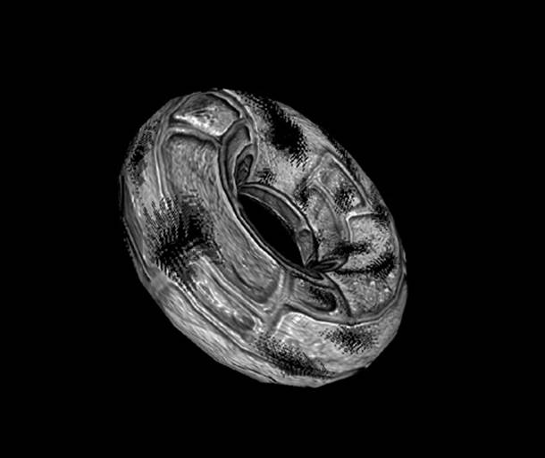
Figure 5-1 Z Fighting Artifacts Due to Not Using Invariance
The same multipass vertex shaders using invariance for position produce the correct image in Figure 5-2.
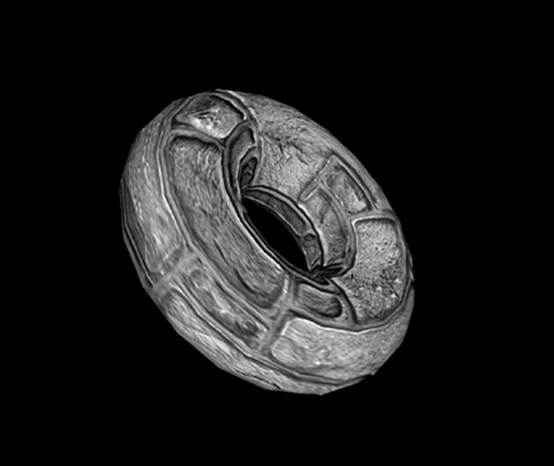
Figure 5-2 Z Fighting Avoided Using Invariance
The introduction of invariance gives the shader writer a way to specify that if the same computations are used to compute an output, its value must be exactly the same (or invariant). The invariant keyword can be used either on varying declarations or for varyings that have already been declared. Some examples follow:
invariant gl_Position;
invariant texCoord;
Once invariance is declared for an output, the compiler guarantees that the results will be the same given the same computations and inputs into the shader. For example, given two vertex shaders that compute output position by multiplying the view projection matrix by the input position, you are guaranteed that those positions will be invariant.
#version 300 es
uniform mat4 u_viewProjMatrix;
layout(location = 0) in vec4 a_vertex;
invariant gl_Position;
void main()
{
// Will be the same value in all shaders with the
// same viewProjMatrix and vertex
gl_Position = u_viewProjMatrix * a_vertex;
}
It is also possible to make all variables globally invariant using a #pragma directive:
#pragma STDGL invariant(all)
A word of caution: Because the compiler needs to guarantee invariance, it might have to limit the optimizations it does. Therefore, the invariant qualifier should be used only when necessary; otherwise, it might result in performance degradation. For this reason, the #pragma directive to globally enable invariance should be used only when invariance is really required for all variables. Note also that while invariance does imply that the calculation will have the same results on a given GPU, it does not mean that the computation will be invariant across any implementation of OpenGL ES.
Summary
This chapter introduced the following features of the OpenGL ES Shading Language:
• Shader version specification with #version
• Scalar, vector, and matrix data types and constructors
• Declaration of constants using the const qualifier
• Creation and initialization of structures and arrays
• Operators, control flow, and functions
• Vertex shader inputs/output and fragment shader inputs/outputs using the in and out keywords and layout qualifier
• Smooth, flat, and centroid interpolation qualifiers
• Uniforms, uniform blocks, and uniform block layout qualifiers
• Preprocessor and directives
• Uniform and interpolator packing
• Precision qualifiers and invariance
In the next chapter, we focus on how to load vertex input variables with data from vertex arrays and vertex buffer objects. We will expand your knowledge of the OpenGL ES Shading Language throughout the book. For example, in Chapter 8, “Vertex Shaders,” we describe how to perform transformation, lighting, and skinning in a vertex shader. In Chapter 9, “Texturing,” we explain how to load textures and how to use them in a fragment shader. In Chapter 10, “Fragment Shaders,” we cover how to compute fog, perform alpha testing, and evaluate user clip planes in a fragment shader. In Chapter 14, “Advanced Programming with OpenGL ES 3.0,” we go deep into writing shaders that perform advanced effects such as environment mapping, projective texturing, and per-fragment lighting. With the grounding in the OpenGL ES Shading Language from this chapter, we can show you how to use shaders to achieve a variety of rendering techniques.
All materials on the site are licensed Creative Commons Attribution-Sharealike 3.0 Unported CC BY-SA 3.0 & GNU Free Documentation License (GFDL)
If you are the copyright holder of any material contained on our site and intend to remove it, please contact our site administrator for approval.
© 2016-2026 All site design rights belong to S.Y.A.