Programming the Raspberry Pi: Getting Started with Python (2013)
10. Prototyping Project (Clock)
In this chapter, we will build what can only be seen as a grossly over-engineered LED digital clock. We will be using a Raspberry Pi, Adafruit’s Cobbler lead, a breadboard, and a four-digit LED display (see Figure 10-1).
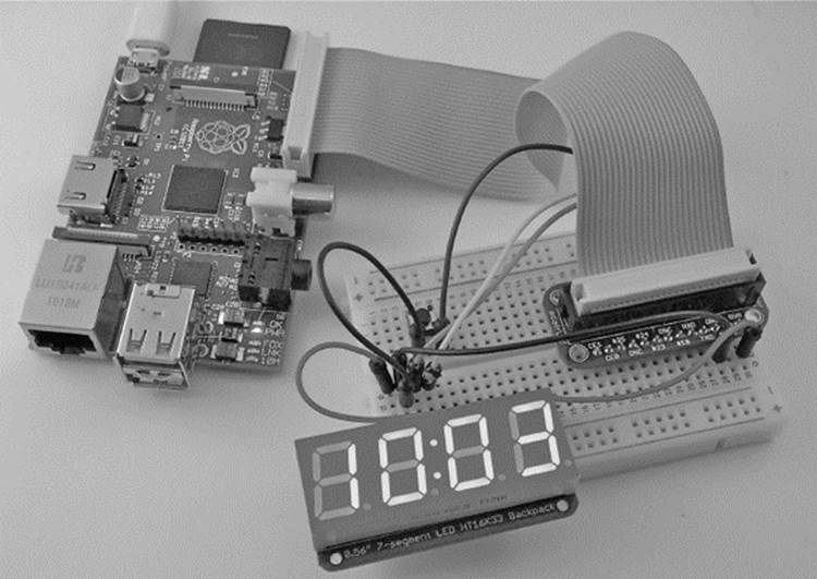
Figure 10-1 LED clock using the Raspberry Pi
In the first phase of the design, the project will just display the time. However, a second phase extends the project by adding a push button that, when pressed, switches the display mode between displaying hours/minutes, seconds, and the date.
![]()
What You Need
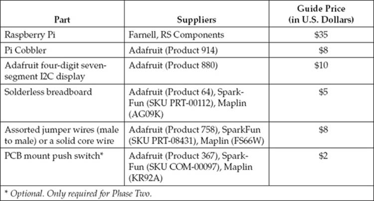
To build this project, you will need the following parts. Suggested part suppliers are listed, but you can also find these parts elsewhere on the Internet.
![]()
Hardware Assembly
Both the Pi Cobbler and the display modules from Adafruit come as kits that must be soldered together before they can be used. Both are fairly easy to solder, and detailed step-by-step instructions for building them can be found on the Adafruit website. Each module has pins that just push into the holes on the breadboard.
The display has just four pins (VCC, GND, SDA, and SCL) when it is plugged into the breadboard; align it so that the VCC pin is on row 1 of the breadboard.
The Cobbler has 26 pins, but we will only be using a few of them. It should be inserted at the other end of the breadboard, or at least far enough away so that none of the pins overlap with the same rows as the display. The Cobbler socket has a cutout on one side to ensure that the ribbon cable can only be inserted one way. This cutout should be toward the top of the breadboard, as shown in Figure 10-2.
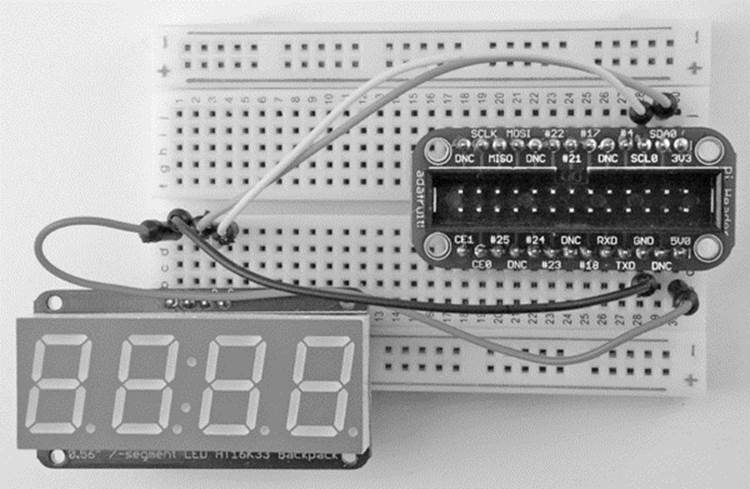
Figure 10-2 Breadboard layout
Underneath the holes of the solderless breadboard are strips of connectors, linking the five holes of a particular row together. Note that because the board is on its side, the rows actually run vertically in Figure 10-2.
Figure 10-2 shows the solderless breadboard with the four pins of the display at one end of the breadboard and the Cobbler at the other. When you’re following the instructions in this chapter, it will help if you insert your modules the same way as Figure 10-2 shows.
NOTE It is much easier to attach the jumper wires to the breadboard without the ribbon cable attached to the Cobbler.
The connections that need to be made are listed here:
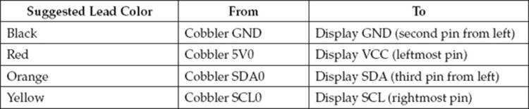
The color scheme shown in this table is only a suggestion; however, it is common to use red for a positive supply and black or blue for the ground connection.
CAUTION In this project, we are connecting a 5V display module to the Raspberry Pi, which generally uses 3.3V. We can only safely do this because the display module used here only acts as a “slave” device and hence only listens on the SDA and SCL lines. Other I2C devices may act as a master device, and if they are 5V, there is a good chance this could damage your Pi. Therefore, before you connect any I2C device to your Raspberry Pi, make sure you understand what you are doing.
We can now link the Cobbler to the Raspberry Pi using the ribbon cable supplied with the Cobbler. This should be done with the Raspberry Pi powered down. The cable will only fit one way into the Cobbler, but no such protection is provided on the Raspberry Pi. Therefore, make sure the red line on the cable is to the outside of the Raspberry Pi, as shown in Figure 10-1.
Turn on the Raspberry Pi. If the usual LEDs do not light, turn it off immediately and check all the wiring.
![]()
Software
Everything is connected, and the Raspberry Pi has booted up. However, the display is still blank because we have not yet written any software to use it. We are going to start with a simple clock that just displays the Raspberry Pi’s system time. The Raspberry Pi does not have a real-time clock to tell it the time. However, it will automatically pick up the time from a network time server if it is connected to the Internet.
The Raspberry Pi displays the time in the bottom-right corner of the screen. If the Pi is not connected to the Internet, you can set the time manually using the following command:
![]()
However, you will have to do this every time you reboot. Therefore, it is far better to have your Raspberry Pi connected to the Internet.
If you are using the network time, you may find that the minutes are correct but that the hour is wrong. This probably means that your Raspberry Pi does now know which time zone it is in. This can be fixed by using the following command, which opens up a window where you can select your continent and then the city for the time zone you require:
![]()
At the time of writing, in order to use the I2C bus that the display uses, the Raspbian Wheezy distribution requires that you issue a few commands to make the I2C bus accessible to the Python program we are going to write. It is likely that later releases of Raspbian (and other distributions) will have the port already configured so that the following commands are not necessary. However, for the moment, here is what you need to do:

NOTE You may find that you have to issue the last two of these commands each time you reboot the Raspberry Pi.
So now that the Raspberry Pi knows the correct time and the I2C bus is available, we can write a Python program that sends the time to the display. To help simplify this process, I have produced a Python library module specifically for this kind of display. It can be downloaded fromhttp://code.google.com/p/i2c7segment/downloads/list.
As with other modules you have installed, you need to fetch the file, extract it into some convenient location (using tar -xzf), and then issue the following command to install it under Python 2:
![]()
The actual clock program itself is contained in the file bundle that accompanies this book (see www.raspberrypibook.com); it is called 10_01_clock.py and is listed here:
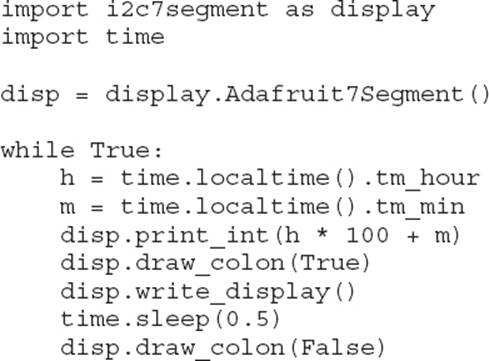
The program is nice and simple. The loop continues forever, getting the hour and minute and showing them in the correct places on the display by multiplying the hour by 100 to shift it into the leftmost digits and then adding the minutes that will appear on the right.
The i2c7segment library does most of the work for us. This library is used by first setting what is to be displayed using print_int or draw_colon and then using write_display to update what is displayed.
The colon is made to flash by turning it on, waiting half a second, and then turning it off again. Access to the I2C port is only available to super-users, so you need to run the command as a super-user by entering the following:
![]()
If everything is working okay, your display should show the time.
![]()
Phase Two
Having got the basic display working, let’s expand both the hardware and software by adding a button that changes the mode of the display, cycling between the time in hours and minutes, the seconds, and the date. Figure 10-3 shows the breadboard with the switch added as well as two new patch wires. Note that we are just adding to the layout of the first phase by adding the button; nothing else is changed.
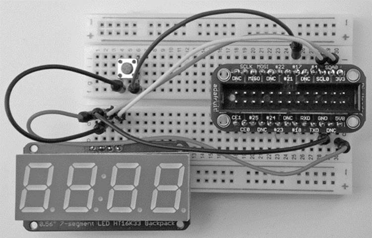
Figure 10-3 Adding a button to the design
NOTE Shut down and power off your Pi before you start making changes on the breadboard.
The button has four leads and must be placed in the right position; otherwise, the switch will appear to be closed all the time. The leads should emerge from the sides facing the top and bottom of Figure 10-3. Don’t worry if you have the switch positioned in the wrong way—it will not damage anything, but the display will continuously change mode without the button being pressed.
Two new wires are needed to connect the switch. One goes from one lead of the switch (refer to Figure 10-3) to the GND connection of the display. The other lead goes to the connection labeled #17 on the Cobbler. The effect is that whenever the button on the switch is pressed, the Raspberry Pi’s GPIO 17 pin will be connected to ground.
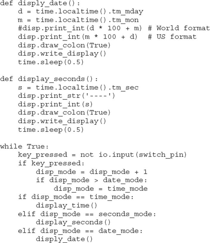
You can find the updated software in the file 10_02_fancy_clock.py and listed here:
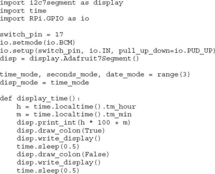
The first thing to notice is that because we need access to GPIO pin 17 to see whether the button is pressed, we need to use the RPi.GPIO library. We used this as an example of installing a module back in Chapter 5. Therefore, if you have not installed RPi.GPIO, refer back to Chapter 5 and do so now.
We set the switch pin to be an input using the following command:
![]()
This command also turns on an internal pull-up resistor that ensures the input is always at 3.3V (high) unless the switch is pressed to override it and pull it low.
Most of what was in the loop has been separated into a function called display_time. Also, two new functions have been added: display_seconds and display_date. These are fairly self-explanatory.
One point of interest is that display_date displays the date in U.S. format. If you want to change this to the international format, where the day of the month comes before the month, change the line that starts with disp.print_int appropriately (refer to the comments in the code).
To keep track of which mode we are in, we have added some new variables in the following lines:

The first of these lines gives each of the three variables a different number. The second line sets the disp_mode variable to the value of time_mode, which we use later in the main loop.
The main loop has been changed to determine whether the button is pressed. If it is, then 1 is added to disp_mode to cycle the display mode. If the display mode has reached the end, it is set back to time_mode.
Finally, the if blocks that follow select the appropriate display function, depending on the mode, and then call it.
![]()
Summary
This project’s hardware can quite easily be adapted to other uses. You could, for example, present all sorts of things on the display by modifying the program. Here are some ideas:
• Your current Internet bandwidth (speed)
• The number of e-mails in your inbox
• A countdown of the days remaining in the year
• The number of visitors to a website
In the next chapter, we build another hardware project—this time a roving robot—using the Raspberry Pi as its brain.