Practical Reverse Engineering: x86, x64, ARM, Windows Kernel, Reversing Tools, and Obfuscation (2014)
Chapter 3. The Windows Kernel
This chapter discusses the principles and techniques necessary for analyzing kernel-mode driver code, such as rootkits, on the Windows platform. Because drivers interact with the OS through well-defined interfaces, the analytical task can be decomposed into the following general objectives:
· Understand how core OS components are implemented
· Understand the structure of a driver
· Understand the user-driver and driver-OS interfaces and how Windows implements them
· Understand how certain driver software constructs are manifested in binary form
· Systematically apply knowledge from the previous steps in the general reverse engineering process
If the process of reverse engineering Windows drivers could be modeled as a discrete task, 90% would be understanding how Windows works and 10% would be understanding assembly code. Hence, the chapter is written as an introduction to the Windows kernel for reverse engineers. It begins with a discussion of the user-kernel interfaces and their implementation. Next, it discusses linked lists and how they are used in Windows. Then it explains concepts such as threads, processes, memory, interrupts, and how they are used in the kernel and drivers. After that it goes into the architecture of a kernel-mode driver and the driver-kernel programming interface. It concludes by applying these concepts to the reverse engineering of a rootkit.
Unless specified otherwise, every example in this chapter is taken from Windows 8 RTM.
Windows Fundamentals
We begin with a discussion of core Windows kernel concepts, including fundamental data structures and kernel objects relevant to driver programming and reverse engineering.
Memory Layout
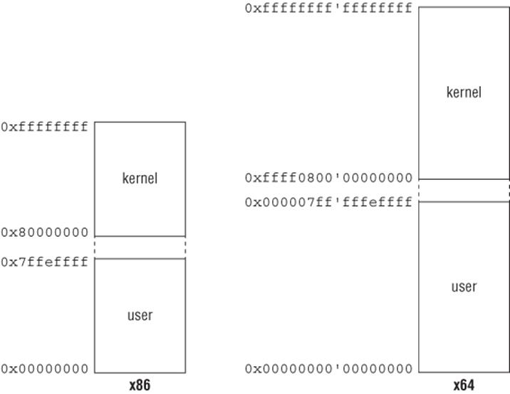
Like many operating systems, Windows divides the virtual address space into two portions: kernel and user space. On x86 and ARM, the upper 2GB is reserved for the kernel and the bottom 2GB is for user processes. Hence, virtual addresses from 0 to 0x7fffffff are in user space, 0x80000000 and above are in kernel space. On x64, the same concept applies except that user space is from 0 to 0x000007ff‘ffffffff and kernel space is 0xffff0800‘00000000 and above. Figure 3.1 illustrates the general layout on x86 and x64. The kernel memory space is mostly the same in all processes. However, running processes only have access to their user address space; kernel-mode code can access both. (Some kernel address ranges, such as those in session and hyper space, vary from process to process.) This is an important fact to keep in mind because we will come back to it later when discussing execution context. Kernel- and user-mode pages are distinguished by a special bit in their page table entry.
Figure 3.1
When a thread in a process is scheduled for execution, the OS changes a processor-specific register to point to the page directory for that particular process. This is so that all virtual-to-physical address translations are specific to the process and not others. This is how the OS can have multiple processes and each one has the illusion that it owns the entire user-mode address space. On x86 and x64 architectures, the page directory base register is CR3; on ARM it is the translation table base register (TTBR).
Note
It is possible to change this default behavior by specifying the /3GB switch in the boot options. With /3GB, the user address space increases to 3GB and the remaining 1GB is for the kernel.
The user/kernel address ranges are stored in two symbols in the kernel: MmSystemRangeStart (kernel) and MmHighestUserAddress (user). These symbols can be viewed with a kernel debugger. You may notice that there is a 64KB gap between user/kernel space on x86/ARM. This region, usually referred to as the no-access region, is there so that the kernel does not accidentally cross the address boundary and corrupt user-mode memory. On x64, the astute reader may notice that 0xffff0800‘00000000 is a non-canonical address and hence unusable by the operating system. This address is really only used as a separator between user/kernel space. The first usable address in kernel space starts at 0xffff8000‘00000000.
Processor Initialization
When the kernel boots up, it performs some basic initialization for each processor. Most of the initialization details are not vital for daily reverse engineering tasks, but it is important to know a few of the core structures.
The processor control region (PCR) is a per-processor structure that stores critical CPU information and state. For example, on x86 it contains the base address of the IDT and current IRQL. Inside the PCR is another data structure called the processor region control block (PRCB). It is a per-processor structure that contains information about the processor—i.e., CPU type, model, speed, current thread that it is running, next thread to run, queue of DPCs to run, and so on. Like the PCR, this structure is undocumented, but you can still view its definition with the kernel debugger:
x64 (x86 is similar)
PCR
0: kd> dt nt!_KPCR
+0x000 NtTib : _NT_TIB
+0x000 GdtBase : Ptr64 _KGDTENTRY64
+0x008 TssBase : Ptr64 _KTSS64
+0x010 UserRsp : Uint8B
+0x018 Self : Ptr64 _KPCR
+0x020 CurrentPrcb : Ptr64 _KPRCB
…
+0x180 Prcb : _KPRCB
PRCB
0: kd> dt nt!_KPRCB
+0x000 MxCsr : Uint4B
+0x004 LegacyNumber : UChar
+0x005 ReservedMustBeZero : UChar
+0x006 InterruptRequest : UChar
+0x007 IdleHalt : UChar
+0x008 CurrentThread : Ptr64 _KTHREAD
+0x010 NextThread : Ptr64 _KTHREAD
+0x018 IdleThread : Ptr64 _KTHREAD
…
+0x040 ProcessorState : _KPROCESSOR_STATE
+0x5f0 CpuType : Char
+0x5f1 CpuID : Char
+0x5f2 CpuStep : Uint2B
+0x5f2 CpuStepping : UChar
+0x5f3 CpuModel : UChar
+0x5f4 MHz : Uint4B
…
+0x2d80 DpcData : [2] _KDPC_DATA
+0x2dc0 DpcStack : Ptr64 Void
+0x2dc8 MaximumDpcQueueDepth : Int4B
…
ARM
PCR
0: kd> dt nt!_KPCR
+0x000 NtTib : _NT_TIB
+0x000 TibPad0 : [2] Uint4B
+0x008 Spare1 : Ptr32 Void
+0x00c Self : Ptr32 _KPCR
+0x010 CurrentPrcb : Ptr32 _KPRCB
…
PRCB
0: kd> dt nt!_KPCR
+0x000 NtTib : _NT_TIB
+0x000 TibPad0 : [2] Uint4B
+0x008 Spare1 : Ptr32 Void
+0x00c Self : Ptr32 _KPCR
+0x010 CurrentPrcb : Ptr32 _KPRCB
…
0: kd> dt nt!_KPRCB
+0x000 LegacyNumber : UChar
+0x001 ReservedMustBeZero : UChar
+0x002 IdleHalt : UChar
+0x004 CurrentThread : Ptr32 _KTHREAD
+0x008 NextThread : Ptr32 _KTHREAD
+0x00c IdleThread : Ptr32 _KTHREAD
…
+0x020 ProcessorState : _KPROCESSOR_STATE
+0x3c0 ProcessorModel : Uint2B
+0x3c2 ProcessorRevision : Uint2B
+0x3c4 MHz : Uint4B
…
+0x690 DpcData : [2] _KDPC_DATA
+0x6b8 DpcStack : Ptr32 Void
…
+0x900 InterruptCount : Uint4B
+0x904 KernelTime : Uint4B
+0x908 UserTime : Uint4B
+0x90c DpcTime : Uint4B
+0x910 InterruptTime : Uint4B
…
The PCR for a current processor is always accessible from kernel-mode through special registers. It is stored in the FS segment (x86), GS segment (x64), or one of the system coprocessor registers (ARM). For example, the Windows kernel exports two routines to get the current EPROCESS and ETHREAD: PsGetCurrentProcess and PsGetCurrentThread. These routines work by querying the PCR/PRCB:
PsGetCurrentThread proc near
mov rax, gs:188h ; gs:[0] is the PCR, offset 0x180 is the PRCB,
; offset 0x8 into the PRCB is the CurrentThread field
retn
PsGetCurrentThread endp
PsGetCurrentProcess proc near
mov rax, gs:188h ; get current thread (see above)
mov rax, [rax+0B8h] ; offset 0x70 into the ETHREAD is the associated
; process(actually ETHREAD.ApcState.Process)
retn
PsGetCurrentProcess endp
System Calls
An operating system manages hardware resources and provides interfaces through which users can request them. The most commonly used interface is the system call. A system call is typically a function in the kernel that services I/O requests from users; it is implemented in the kernel because only high-privilege code can manage such resources. For example, when a word processor saves a file to disk, it first needs to request a file handle from the kernel, writes to the file, and then commits the file content to the hard disk; the OS provides system calls to acquire a file handle and write bytes to it. While these appear to be simple operations, the system calls must perform many important tasks in the kernel to service the request. For example, to get a file handle, it must interact with the file system (to determine whether the path is valid or not) and then ask the security manager to determine whether the user has sufficient rights to access the file; to write bytes to the file, the kernel needs to figure out which hard drive volume the file is on, send the request to the volume, and package the data into a structure understood by the underlying hard-drive controller. All these operations are done with complete transparency to the user.
The Windows system call implementation details are officially undocumented, so it is worth exploring for intellectual and pedagogical reasons. While the implementation varies between processors, the concepts remain the same. We will first explain the concepts and then discuss the implementation details on x86, x64, and ARM.
Windows describes and stores system call information with two data structures: a service table descriptor and an array of function pointers/offsets. The service table descriptor is a structure that holds metadata about system calls supported by the OS; its definition is officially undocumented, but many people have reverse engineered its important field members as follows. (You can also figure out these fields by analyzing the KiSystemCall64 or KiSystemService routines.)
typedef struct _KSERVICE_TABLE_DESCRIPTOR
{
PULONG Base; // array of addresses or offsets
PULONG Count;
ULONG Limit; // size of the array
PUCHAR Number;
…
} KSERVICE_TABLE_DESCRIPTOR, *PKSERVICE_TABLE_DESCRIPTOR;
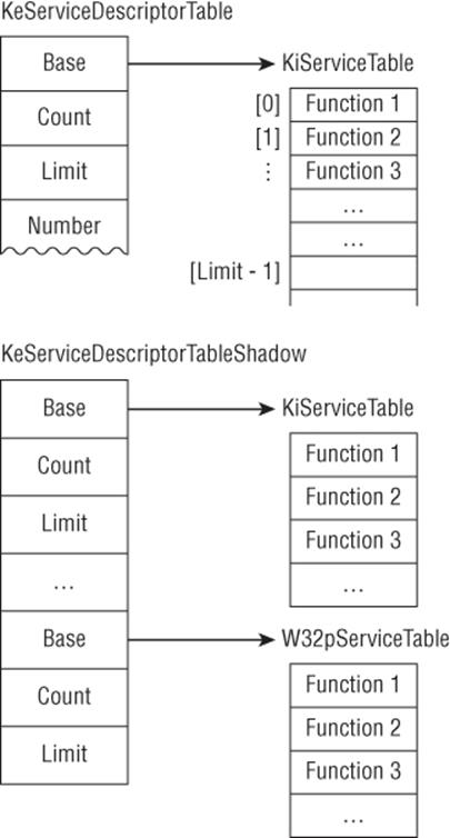
Base is a pointer to an array of function pointers or offsets (depending on the processor); a system call number is an index into this array. Limit is the number of entries in the array. The kernel keeps two global arrays of KSERVICE_DESCRIPTOR_DESCRIPTOR: KeServiceDescriptorTable andKeServiceDescriptorTableShadow. The former contains the native syscall table; the latter contains the same data, in addition to the syscall table for GUI threads. The kernel also keeps two global pointers to the arrays of addresses/offsets: KiServiceTable points to the non-GUI syscall table andW32pServiceTable points to the GUI one. Figure 3.2 illustrates how these data structures are related to each other on x86.
Figure 3.2
On x86, the Base field is an array of function pointers for the syscalls:
0: kd> dps nt!KeServiceDescriptorTable
81472400 813564d0 nt!KiServiceTable ; Base
81472404 00000000
81472408 000001ad
8147240c 81356b88 nt!KiArgumentTable
0: kd> dd nt!KiServiceTable
813564d0 81330901 812cf1e2 81581540 816090af
813564e0 815be478 814b048f 8164e434 8164e3cb
813564f0 812dfa09 814e303f 814a0830 81613a9f
81356500 814e5b65 815b9e3a 815e0c4e 8158ce33
…
0: kd> dps nt!KiServiceTable
813564d0 81330901 nt!NtWorkerFactoryWorkerReady
813564d4 812cf1e2 nt!NtYieldExecution
813564d8 81581540 nt!NtWriteVirtualMemory
813564dc 816090af nt!NtWriteRequestData
813564e0 815be478 nt!NtWriteFileGather
813564e4 814b048f nt!NtWriteFile
However, on x64 and ARM, it is an array of 32-bit integers which encodes the system call offset and number of arguments passed on the stack. The offset is contained in the top 20 bits, and the number of arguments on the stack is contained in the bottom 4 bits. The offset is added to the base ofKiServiceTable to get the real address of the syscall. For example:
0: kd> dps nt!KeServiceDescriptorTable
fffff803'955cd900 fffff803'952ed200 nt!KiServiceTable ; Base
fffff803'955cd908 00000000'00000000
fffff803'955cd910 00000000'000001ad
fffff803'955cd918 fffff803'952edf6c nt!KiArgumentTable
0: kd> u ntdll!NtCreateFile
ntdll!NtCreateFile:
000007f8'34f23130 mov r10,rcx
000007f8'34f23133 mov eax,53h ; syscall number
000007f8'34f23138 syscall
…
0: kd> x nt!KiServiceTable
fffff803'952ed200 nt!KiServiceTable (<no parameter info>)
0: kd> dd nt!KiServiceTable + (0x53*4) L1
fffff803'952ed34c 03ea2c07 ; encoded offset and number of arguments
0: kd> u nt!KiServiceTable + (0x03ea2c07![]() 4) ; get the offset and add it to Base
4) ; get the offset and add it to Base
nt!NtCreateFile:
fffff803'956d74c0 sub rsp,88h
fffff803'956d74c7 xor eax,eax
fffff803'956d74c9 mov qword ptr [rsp+78h],rax
fffff803'956d74ce mov dword ptr [rsp+70h],20h
0: kd> ? 0x03ea2c07 & 0xf ; number of arguments
Evaluate expression: 7 = 00000000'00000007
; NtCreateFile takes 11 arguments. The first 4 are passed via registers and
; the last 7 are passed on the stack
As demonstrated, every system call is identified by a number that is an index into KiServiceTable or W32pServiceTable. At the lowest level, user-mode APIs decompose to one or more system calls.
Conceptually, this is how system calls work on Windows. The implementation details vary depending on processor architecture and platform. System calls are typically implemented through software interrupts or architecture-specific instructions, the details of which are covered in the following sections.
Faults, Traps, and Interrupts
In preparation for the next sections, we need to introduce some basic terminology to explain how peripheral devices and software interact with the processor. In contemporary computing systems, the processor is typically connected to peripheral devices through a data bus such as PCI Express, FireWire, or USB. When a device requires the processor's attention, it causes an interrupt that forces the processor to pause whatever it is doing and handle the device's request. How does the processor know how to handle the request? At the highest level, one can think of an interrupt as being associated with a number that is then used to index into an array of function pointers. When the processor receives the interrupt, it executes the function at the index associated with the request and resumes execution wherever it was before the interrupt occurred. These are called hardware interruptsbecause they are generated by hardware devices. They are asynchronous by nature.
When the processor is executing an instruction, it may run into exceptions. For example, the instruction causes a divide-by-zero error, references an invalid address, or triggers privilege-level transition. For the purpose of this discussion, exceptions can be classified into two categories: faults and traps. A fault is a correctable exception. For example, when the processor executes an instruction that references a valid memory address but the data is not present in main memory (it was paged out), a page fault exception is generated. The processor handles this by saving the current execution state, calls the page fault handler to correct this exception (by paging in the data), and re-executes the same instruction (which should no longer cause a page fault). A trap is an exception caused by executing special kinds of instructions. For example, on x64, the instruction SYSCALL causes the processor to begin executing at an address specified by an MSR; after the handler is done, execution is resumed at the instruction immediately after SYSCALL. Hence, the major difference between a fault and a trap is where execution resumes. System calls are commonly implemented through special exceptions or trap instructions.
Interrupts
The Intel architecture defines an interrupt descriptor table (IDT) with 256 entries; each entry is a structure with information defining the interrupt handler. The base address of the IDT is stored in a special register called IDTR. An interrupt is associated with an index into this table. There are predefined interrupts reserved by the architecture. For example, 0x0 is for division exception, 0x3 is for software breakpoint, and 0xe is for page faults. Interrupts 32–255 are user-defined.
On x86, each entry in the IDT table is an 8-byte structure defined as follows:
1: kd> dt nt!_KIDTENTRY
+0x000 Offset : Uint2B
+0x002 Selector : Uint2B
+0x004 Access : Uint2B
+0x006 ExtendedOffset : Uint2B
(On x64, the IDT entry structure is mostly the same except that the interrupt handler's address is divided into three members. You can see it by dumping the nt!_KIDTENTRY64 structure. Also note that the IDTR is 48 bits in width and divided into two parts: IDT base address and limit. WinDBG displays only the base address.)
The interrupt handler's address is split between the Offset and ExtendedOffset fields. Here is an example decoding the IDT and disassembling the divide-by-zero interrupt handler (0x0):
1: kd> r @idtr
idtr=8b409d50
1: kd> dt nt!_KIDTENTRY 8b409d50
+0x000 Offset : 0xa284
+0x002 Selector : 8
+0x004 Access : 0x8e00
+0x006 ExtendedOffset : 0x813c
1: kd> u 0x813ca284
nt!KiTrap00:
813ca284 push 0
813ca286 mov word ptr [esp+2],0
813ca28d push ebp
813ca28e push ebx
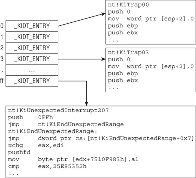
Figure 3.3 illustrates the IDT on x86.
Figure 3.3
On pre-Pentium 2 processors, Windows uses interrupt 0x2e to implement system calls. User-mode programs call APIs in kernel32.dll (or kernelbase.dll), which eventually resolve to short stubs in ntdll.dll that trigger interrupt 0x2e. To illustrate, consider the following snippet from thekernelbase!CreateFileW API routine on Windows 7:
[inside kernelbase!CreateFileW]
…
.text:0DCE9C87 mov ecx, [ebp+dwFlagsAndAttributes]
.text:0DCE9C8A push [ebp+lpSecurityAttributes]
.text:0DCE9C8D mov eax, [ebp+dwDesiredAccess]
.text:0DCE9C90 push [ebp+lpFileName]
.text:0DCE9C93 mov esi, ds:__imp__NtCreateFile@44
.text:0DCE9C99 push [ebp+var_4]
.text:0DCE9C9C and ecx, 7FA7h
.text:0DCE9CA2 push [ebp+dwShareMode]
.text:0DCE9CA5 mov [ebp+dwFlagsAndAttributes], ecx
.text:0DCE9CA8 push ecx
.text:0DCE9CA9 push ebx
.text:0DCE9CAA lea ecx, [ebp+var_20]
.text:0DCE9CAD push ecx
.text:0DCE9CAE or eax, 100080h
.text:0DCE9CB3 lea ecx, [ebp+var_64]
.text:0DCE9CB6 push ecx
.text:0DCE9CB7 push eax
.text:0DCE9CB8 mov [ebp+dwDesiredAccess], eax
.text:0DCE9CBB lea eax, [ebp+var_8]
.text:0DCE9CBE push eax
.text:0DCE9CBF call esi ; NtCreateFile(…)
It does some preliminary validation (not shown here) and then calls ntdll!NtCreateFile. The implementation for that is as follows:
[ntdll!NtCreateFile]
.text:77F04A10 _NtCreateFile@44 proc near
.text:77F04A10 mov eax, 42h ; syscall #
.text:77F04A15 mov edx, 7FFE0300h ; KUSER_SHARED_DATA.SystemCall
; the symbol for 0x7ffe0300 is SharedUserData!SystemCallStub
.text:77F04A1A call dword ptr [edx] ; call handler
.text:77F04A1C retn 2Ch ; return back to caller
.text:77F04A1C _NtCreateFile@44 endp
NtCreateFile sets EAX to 0x42 because that's the system call number for NtCreateFile in the kernel. Next, it reads a pointer at 0x7ffe0300 and calls it. What is special about 0x7ffe0300? On all architectures, there is a per-process structure called KUSER_SHARED_DATA that is always mapped at0x7ffe0000. It contains some generic information about the system and a field called SystemCall:
0:000> dt ntdll!_KUSER_SHARED_DATA
+0x000 TickCountLowDeprecated : Uint4B
+0x004 TickCountMultiplier : Uint4B
+0x008 InterruptTime : _KSYSTEM_TIME
+0x014 SystemTime : _KSYSTEM_TIME
+0x020 TimeZoneBias : _KSYSTEM_TIME
…
+0x2f8 TestRetInstruction : Uint8B
+0x300 SystemCall : Uint4B ; syscall handler
+0x304 SystemCallReturn : Uint4B
…
When disassembling the system call stub, you see this:
0:000> u poi(SharedUserData!SystemCallStub)
ntdll!KiIntSystemCall:
76e46500 lea edx,[esp+8]
76e46504 int 2Eh
76e46506 ret
76e46507 nop
Dumping the IDT entry at index 0x2e shows that KiSystemService is the system call dispatcher:
0: kd> !idt 0x2e
Dumping IDT: …
2e: 8284b22e nt!KiSystemService
0: kd> u nt!KiSystemService
nt!KiSystemService:
8284b22e push 0
8284b230 push ebp
8284b231 push ebx
8284b232 push esi
8284b233 push edi
8284b234 push fs
8284b236 mov ebx,30h
…
The details of the system call dispatcher are covered in the next section.
Traps
The previous section explains how system calls are implemented with the built-in interrupt processing mechanism. This section explains how they are implemented through trap instructions on x64, x86, and ARM.
Beginning with the implementation on x64, consider the system call stub ntdll!NtCreateFile:
01: .text:00000001800030F0 public ZwCreateFile
02: .text:00000001800030F0 ZwCreateFile proc near
03: .text:00000001800030F0 mov r10, rcx
04: .text:00000001800030F3 mov eax, 53h
05: .text:00000001800030F8 syscall
06: .text:00000001800030FA retn
07: .text:00000001800030FA ZwCreateFile endp
Line 3 saves the first argument to R10; it has to do this because SYSCALL's semantic dictates that the return address (line 6) must be stored in RCX. Line 4 saves the system call number in EAX; once SYSCALL transitions to kernel mode, it will use this as an index into the KiServiceTable array. Line 5 executes SYSCALL which transitions to kernel mode. How does it do this? The documentation for SYSCALL specifies that RIP will be loaded with a value defined by the IA32_LSTAR MSR (0xc0000082), and you can observe it in the debugger:
1: kd> rdmsr 0xC0000082
msr[c0000082] = fffff800'89e96dc0
1: kd> u fffff800'89e96dc0
nt!KiSystemCall64:
fffff800'89e96dc0 swapgs
fffff800'89e96dc3 mov qword ptr gs:[10h],rsp
fffff800'89e96dcc mov rsp,qword ptr gs:[1A8h]
fffff800'89e96dd5 push 2Bh
fffff800'89e96dd7 push qword ptr gs:[10h]
fffff800'89e96ddf push r11
This kernel debugger output indicates that SYSCALL will always end up executing KiSystemCall64 in the kernel. In fact, KiSystemCall64 is the main system call dispatcher in x64 Windows. Windows sets the IA32 LSTAR MSR to KiSystemCall64 early in the processor initialization process (seeKiInitializeBootStructures). It is primarily responsible for saving the user-mode context, setting up a kernel stack, copying the user-mode arguments to the kernel stack, determining the system call in KiServiceTable (or W32pServiceTable) using the index passed in from EAX, invoking the system call, and returning to user mode. How does the syscall dispatcher know where to return in user mode? Recall that SYSCALL saves the return address in RCX. After the system call finishes its work and returns, the system call dispatcher uses the SYSRET instruction, which sets RIP to RCX so it goes back to user mode.
While KiSystemCall64 supports many functionalities (syscall profiling, user-mode scheduling, debugging, etc.), its primary responsibility is to dispatch system call requests. In the previous section, we stated that each value in the KiServiceTable array encodes an offset to the system call and the number of arguments passed on the stack. This can be observed in the following code snippet from KiSystemCall64:
01: KiSystemCall64 proc near
02:
03: var_110= byte ptr -110h
04:
05: swapgs
06: mov gs:10h, rsp ; KPCR->UserRsp
07: mov rsp, gs:1A8h ; KPCR->KPRCB->RspBase
08: ; setup a new kernel stack
09: push 2Bh
10: push qword ptr gs:10h ; KPCR->UserRsp
11: push r11
12:
13: sti ; enable interrupts
14: mov [rbx+88h], rcx ; KTHREAD->FirstArgument
15: mov [rbx+80h], eax ; KTHREAD->SystemCallNumber
16: KiSystemServiceStart proc near
17: mov [rbx+90h], rsp ; KTHREAD->TrapFrame
18: mov edi, eax ; eax = syscall #
19: shr edi, 7 ; determine which syscall table
20: and edi, 20h
21: and eax, 0FFFh ; index into table (recall 64bit syscall encoding)
22: KiSystemServiceRepeat proc near
23: lea r10, KeServiceDescriptorTable
24: lea r11, KeServiceDescriptorTableShadow
25: test dword ptr [rbx+78h], 40h ; determines if it is a GUI thread
26: cmovnz r10, r11 ; which table to use?
27: cmp eax, [rdi+r10+10h] ; is that syscall table within the table Limit?
28: ; i.e., KSERVICE_TABLE_DESCRIPTOR.Limit
29: jnb case_invalidcallnumber
30: mov r10, [rdi+r10] ; select the right table
31: movsxd r11, dword ptr [r10+rax*4] ; get the syscall offset
32: mov rax, r11
33: sar r11, 4
34: add r10, r11 ; add it to the base of the table to get syscall VA
35: cmp edi, 20h ; edi determines which table. here it is used to
; determined if it is a GUI
36: jnz short case_nonguirequest
37: mov r11, [rbx+0F0h]
38:
39: KiSystemServiceCopyEnd proc near
40: test cs:dword_140356088, 40h
41: jnz case_loggingenabled
42: call r10 ; invoke the system call
Walking through KiSystemCall64 can be an instructional experience and is left as an exercise.
On x86, Windows uses the SYSENTER instruction to implement system calls. The mechanics is similar to that of SYSCALL on x64 processors. Before going into the implementation, let's look at the system call stub for ntdll!NtQueryInformationProcess:
01: _ZwQueryInformationProcess@20 proc near
02: mov eax, 0B0h ; system call number
03: call sub_6A214FCD ; stub
04: retn 14h ; clean stack and return. NtQueryInformationProcess takes
05: ; 5 parameters and they are passed on the stack
; SYSENTER will return here (see next example)
06: _ZwQueryInformationProcess@20 endp
07:
08: sub_6A214FCD proc near
09: mov edx, esp
10: sysenter
11: retn
12: sub_6A214FCD endp
ntdll!NtCreateFile sets the system call number and calls another routine that saves the stack pointer in EDX, followed by the SYSENTER instruction. Intel documentation states that SYSENTER sets EIP to the value stored in MSR 0x176:
0: kd> rdmsr 0x176
msr[176] = 00000000'80f7d1d0
0: kd> u 00000000'80f7d1d0
nt!KiFastCallEntry:
80f7d1d0 mov ecx,23h
80f7d1d5 push 30h
80f7d1d7 pop fs
80f7d1d9 mov ds,cx
80f7d1db mov es,cx
80f7d1dd mov ecx,dword ptr fs:[40h]
The debugger output shows that when the instruction SYSENTER executes, it transitions to kernel mode and starts executing KiFastCallEntry. KiFastCallEntry is the main system call dispatcher on x86 Windows using SYSENTER (think of it like KiSystemCall64 on x64). One peculiar characteristic of SYSENTER is that it does not save the return address in a register as SYSCALL does. Once the system call is complete, how does the kernel know where to return? The answer consists of two parts. Using NtQueryInformationProcess again as an example, before calling SYSENTER to enter kernel mode, first the sequence of calls looks like this:
kernel32!GetLogicalDrives ->
ntdll!NtQueryInformationProcess ->
stub -> SYSENTER
This means that the return address is already set up on the stack before SYSENTER is executed. Immediately before SYSENTER, KiFastSystemCall saves the stack pointer in EDX. Second, after SYSENTER, the code transitions to KiFastCallEntry, which saves this stack pointer. Once the system call is complete, the syscall dispatcher executes the SYSEXIT instruction. By definition, SYSEXIT sets EIP to EDX, and ESP to ECX; in practice, the kernel sets EDX to ntdll!KiSystemCallRet and ECX to the stack pointer before entering the kernel. You can observe this in action by setting a breakpoint at theSYSEXIT instruction inside KiSystemCallExit2 and then viewing the stack from there:
1: kd> r
eax=00000000 ebx=00000000 ecx=029af304 edx=77586954 esi=029af3c0 edi=029afa04
eip=815d0458 esp=a08f7c8c ebp=029af3a8 iopl=0 nv up ei ng nz na pe cy
cs=0008 ss=0010 ds=0023 es=0023 fs=0030 gs=0000 efl=00000287
nt!KiSystemCallExit2+0x18:
815d0458 sysexit
1: kd> dps @ecx L5 # SYSEXIT will set ESP to ECX (note the return address)
029af304 77584fca ntdll!NtQueryInformationProcess+0xa # return address
029af308 775a9628 ntdll!RtlDispatchException+0x7c
029af30c ffffffff
029af310 00000022
029af314 029af348
1: kd> u 77584fca
ntdll!NtQueryInformationProcess+0xa:
77584fca ret 14h # this is line 4 in the last snippet
1: kd> u @edx # SYSEXIT will set EIP to EDX
ntdll!KiFastSystemCallRet:
77586954 ret # return to 77584fca
After executing KiFastSystemCallRet (which has only one instruction: RET), you return to NtQueryInformationProcess.
It is instructive to compare the SYSENTER implementation on Windows 7 and 8. You will be asked to do this as an exercise.
Windows on ARM uses the SVC instruction to implement system calls. In older documentation, SVC may be referred to as SWI, but they are the same opcode. Recall that ARM does not have an IDT like x86/x64 but its exception vector table has similar functionality:
.text:004D0E00 KiArmExceptionVectors
.text:004D0E00 LDR.W PC, =0xFFFFFFFF
.text:004D0E04 LDR.W PC, =(KiUndefinedInstructionException+1)
.text:004D0E08 LDR.W PC, =(KiSWIException+1)
.text:004D0E0C LDR.W PC, =(KiPrefetchAbortException+1)
.text:004D0E10 LDR.W PC, =(KiDataAbortException+1)
.text:004D0E14 LDR.W PC, =0xFFFFFFFF
.text:004D0E18 LDR.W PC, =(KiInterruptException+1)
.text:004D0E1C LDR.W PC, =(KiFIQException+1)
Whenever the SVC instruction is executed, the processor switches to supervisor mode and calls KiSWIException to handle the exception. This function can be viewed as the ARM equivalence of KiSystemCall64 on x64. Again, to understand the whole system call process on ARM, consider the user-mode function ntdll!NtQueryInformationProcess:
01: NtQueryInformationProcess
02: MOV.W R12, #0x17 ; NtQueryInformationProcess
03: SVC 1
04: BX LR
The system call number is first put in R12 and followed by SVC. When SVC is executed, you go into the handler KiSWIException:
01: KiSWIException
02: trapframe= -0x1A0
03: SUB SP, SP, #0x1A0
04: STRD.W R0, R1, [SP,#0x1A0+trapframe._R0]
05: STRD.W R2, R3, [SP,#0x1A0+trapframe._R2]
06: STR.W R12, [SP,#0x1A0+trapframe._R12]
07: STR.W R11, [SP,#0x1A0+trapframe._R11]
08: ORR.W LR, LR, #1
09: MOVS R0, #0x30
10: MRC p15, 0, R12,c13,c0, 3 ; get the current thread
11: STRD.W LR, R0, [SP,#0x1A0+trapframe._Pc] ; LR is the return
; address after the
; SVC instruction. It
; saved here so the
; system knows where to
; return after the
; syscall is done
12: LDRB.W R1, [R12,#_ETHREAD.Tcb.Header.___u0.__s3.DebugActive]
13: MOVS R3, #2
14: STR R3, [SP,#0x1A0+trapframe.ExceptionActive]
15: ADD.W R11, SP, #0x1A0+trapframe._R11
16: CMP R1, #0
17: BNE case_DebugMode
18: loc_4D00D0
19: MRC p15, 0, R0,c1,c0, 2
20: MOVS R1, #0
21: TST.W R0, #0xF00000
22: BEQ loc_4D00F2
23: ADD R3, SP, #0x1A0+var_C8
24: VMRS R2, FPSCR
25: ADD R1, SP, #sizeof(_KTRAP_FRAME)
26: STR R2, [SP,#0x1A0+var_114]
27: VSTMIA R3, {D8-D15}
28: BIC.W R2, R2, #0x370000
29: VMSR FPSCR, R2
30:
31: loc_4D00F2
32: STR R1, [SP,#0x1A0+trapframe.VfpState]
33: LDR R0, [SP,#0x1A0+trapframe._R12] ; retrieve saved syscall
; from line 6
34: LDR R1, [SP,#0x1A0+trapframe._R0]
35: MOV R2, SP
36: CPS.W #0x1F
37: STR.W SP, [R2,#0x1A0+trapframe._Sp]
38: STR.W LR, [R2,#0x1A0+trapframe._Lr]
39: CPSIE.W I, #0x13
40: STRD.W R0, R1, [R12,#_ETHREAD.Tcb.SystemCallNumber]
; write syscall# to the
; thread
41: MRC p15, 0, R0,c13,c0, 4
42: BFC.W R0, #0, #0xC
43: LDR.W R1, [R0,#0x594]
44: MOV R2, #0x5CF300
45: MOV R12, #KiTrapFrameLog
46: CMP R1, #4
47: BCS loc_4D0178
48:
49:
50: loc_4D0178
51: MRC p15, 0, R12,c13,c0, 3
52: LDR.W R0, [R12,#_ETHREAD.Tcb.SystemCallNumber]
53: BL KiSystemService ; dispatch the system call
54: B KiSystemServiceExit ; return back to usermode
This function does many things, but the main points are that it constructs a trap frame (nt!_KTRAP_FRAME) to save some registers, saves the user-mode return address (SVC automatically puts the return address in LR), saves the system call number in the current thread object, and dispatches the system call (same mechanism as x64). The return back to user mode is done through KiSystemServiceExit:
01: KiSystemServiceExit
02: …
03: BIC.W R0, R0, #1
04: MOV R3, SP
05: ADD SP, SP, #0x1A0
06: CPS.W #0x1F
07: LDR.W SP, [R3,#_KTRAP_FRAME._Sp]
08: LDRD.W LR, R11, [R3,#_KTRAP_FRAME._Lr]
09: CPS.W #0x12
10: STRD.W R0, R1, [SP]
11: LDR R0, [R3,#_KTRAP_FRAME._R0]
12: MOVS R1, #0
13: MOVS R2, #0
14: MOVS R3, #0
15: MOV R12, R1
16: RFEFD.W SP ; return back to usermode
Interrupt Request Level
The Windows kernel uses an abstract concept called interrupt request level (IRQL) to manage system interruptability. Interrupts can be divided into two general categories: software and hardware. Software interrupts are synchronous events that are triggered by conditions in the running code (divide by 0, execution of an INT instruction, page fault, etc.); hardware interrupts are asynchronous events that are triggered by devices connected to the CPU. Hardware interrupts are asynchronous because they can happen at any time; they are typically used to indicate I/O operations to the processor. The details of how hardware interrupts work are hardware-specific and hence abstracted away by the hardware abstraction layer (HAL) component of Windows.
Concretely speaking, an IRQL is simply a number (defined by the type KIRQL, which is actually a UCHAR) assigned to a processor. Windows associates an IRQL with an interrupt and defines the order in which it is handled. The exact number associated with each IRQL may vary from platform to platform, so we will reference them only by name. The general rule is that interrupts at IRQL X will mask all interrupts that are less than X. Once the interrupt is handled, the kernel lowers the IRQL so that it can run other tasks. Because IRQL is a per-processor value, multiple processors can simultaneously operate at different IRQLs.
There are several different IRQLs, but the most important ones to remember are as follows:
· PASSIVE LEVEL (0)—This is the lowest IRQL in the system. All user-mode code and most kernel code executes at this IRQL.
· APC LEVEL (1) —This is the IRQL at which asynchronous procedure calls (APCs) are executed. (See the section “Asynchronous Procedure Calls.”)
· DISPATCH LEVEL (2) —This is the highest software IRQL in the system. The thread dispatcher and deferred procedure calls (DPCs) run at this IRQL. (See the section “Deferred Procedure Calls.”) Code at this IRQL cannot wait.
Note
IRQLs higher than DISPATCH_LEVEL are typically associated with real hardware interrupts or extremely low-level synchronization mechanisms. For example, IPI_LEVEL is used for communication between processors.
While it seems like IRQL is a thread-scheduling property, it is not. It is a per-processor property, whereas thread priority is a per-thread property.
Because IRQL is a software abstraction of interrupt priority, the underlying implementation has a direct correlation with the hardware. For example, on x86/x64, the local interrupt controller (LAPIC) in the processor has a programmable task priority register (TPR) and a read-only processor priority register (PPR). The TPR determines the interrupt priority; the PPR represents the current interrupt priority. The processor will deliver only interrupts whose priority is higher than the PPR. In practical terms, when Windows needs to change the interrupt priority, it calls the kernel functionsKeRaiseIrql/KeLowerIrql, which program the TPR on the local APIC. This can be observed in the definition on x64 (on x64, CR8 is a shadow register allowing quick access to the LAPIC TTPR):
KeRaiseIrql
01: KzRaiseIrql proc near
02: mov rax, cr8
03: movzx ecx, cl
04: mov cr8, rcx
05: retn
06: KzRaiseIrql endp
KeLowerIrql
01: KzLowerIrql proc near
02: movzx eax, cl
03: mov cr8, rax
04: retn
05: KzLowerIrql endp
The preceding concepts explain why code running at high IRQL cannot be preempted by code at lower IRQL.
Pool Memory
Similar to user-mode applications, kernel-mode code can allocate memory at run-time. The general name for it is pool memory; one can think it like the heap in user mode. Pool memory is generally divided into two types: paged pool and non-paged pool. Paged pool memory is memory that can be paged out at any given time by the memory manager. When kernel-mode code touches a buffer that is paged out, it triggers a page-fault exception that causes the memory manager to page in that buffer from disk. Non-paged pool memory is memory that can never be paged out; in other words, accessing such memory never triggers a page fault.
This distinction is important because it has consequences for code running at high IRQLs. Suppose a kernel thread is currently running at DISPATCH_LEVEL and it references memory that has been paged out and needs to be handled by the page-fault handler; because the page fault handler (seeMmAccessFault) needs to issue a request to bring the page from disk and the thread dispatcher runs at DISPATCH_LEVEL, it cannot resolve the exception and results in a bugcheck. This is one of the reasons why code running at DISPATCH_LEVEL must only reside in and access non-paged pool memory.
Pool memory is allocated and freed by the ExAllocatePool* and ExFreePool* family of functions. By default, non-paged pool memory (type NonPagedPool) is mapped with read, write, and execute permission on x86/x64, but non-executable on ARM; on Windows 8, one can request non-executable, non-paged pool memory by specifying the NonPagedPoolNX pool type. Paged pool memory is mapped read, write, executable on x86, but non-executable on x64/ARM.
Memory Descriptor Lists
A memory descriptor list (MDL) is a data structure used to describe a set of physical pages mapped by a virtual address. Each MDL entry describes one contiguous buffer, and multiple entries can be linked together. Once an MDL is built for an existing buffer, the physical pages can be locked in memory (meaning they will not be reused) and can be mapped into another virtual address. To be useful, MDLs must be initialized, probed, and locked, and then mapped. To better understand the concept, consider some of the practical uses of MDLs.
Suppose a driver needs to map some memory in kernel space to the user-mode address space of a process or vice versa. In order to achieve this, it would first initialize an MDL to describe the memory buffer (IoAllocateMdl), ensure that the current thread has access to those pages and lock them (MmProbeAndLockPages), and then map those pages in memory (MmMapLockedPagesSpecifyCache) in that process.
Another scenario is when a driver needs to write to some read-only pages (such as those in the code section). One way to achieve this is through MDLs. The driver would initialize the MDL, lock it, and then map it to another virtual address with write permission. In this scenario, the driver can use MDLs to implement a VirtualProtect-like function in kernel mode.
Processes and Threads
A thread is defined by two kernel data structures: ETHREAD and KTHREAD. An ETHREAD structure contains housekeeping information about the thread (i.e., thread id, associated process, debugging enabled/disabled, etc.). A KTHREAD structure stores scheduling information for the thread dispatcher, such as thread stack information, processor on which to run, alertable state, and so on. An ETHREAD contains a KTHREAD.
The Windows scheduler operates on threads.
A process contains at least one thread and is defined by two kernel data structures: EPROCESS and KPROCESS. An EPROCESS structure stores basic information about the process (i.e., process id, security token, list of threads, etc.). A KPROCESS structure stores scheduling information for the process (i.e., page directory table, ideal processor, system/user time, etc.). An EPROCESS contains a KPROCESS. Just like ETHREAD and KTHREAD, these data structures are also opaque and should only be accessed with documented kernel routines. However, you can view their field members through the kernel debugger, as follows:
Processes
kd> dt nt!_EPROCESS
+0x000 Pcb : _KPROCESS
+0x2c8 ProcessLock : _EX_PUSH_LOCK
+0x2d0 CreateTime : _LARGE_INTEGER
+0x2d8 RundownProtect : _EX_RUNDOWN_REF
+0x2e0 UniqueProcessId : Ptr64 Void
+0x2e8 ActiveProcessLinks : _LIST_ENTRY
+0x2f8 Flags2 : Uint4B
+0x2f8 JobNotReallyActive : Pos 0, 1 Bit
+0x2f8 AccountingFolded : Pos 1, 1 Bit
+0x2f8 NewProcessReported : Pos 2, 1 Bit
…
+0x3d0 InheritedFromUniqueProcessId : Ptr64 Void
+0x3d8 LdtInformation : Ptr64 Void
+0x3e0 CreatorProcess : Ptr64 _EPROCESS
+0x3e0 ConsoleHostProcess : Uint8B
+0x3e8 Peb : Ptr64 _PEB
+0x3f0 Session : Ptr64 Void
…
0: kd> dt nt!_KPROCESS
+0x000 Header : _DISPATCHER_HEADER
+0x018 ProfileListHead : _LIST_ENTRY
+0x028 DirectoryTableBase : Uint8B
+0x030 ThreadListHead : _LIST_ENTRY
+0x040 ProcessLock : Uint4B
…
+0x0f0 ReadyListHead : _LIST_ENTRY
+0x100 SwapListEntry : _SINGLE_LIST_ENTRY
+0x108 ActiveProcessors : _KAFFINITY_EX
…
Threads
0: kd> dt nt!_ETHREAD
+0x000 Tcb : _KTHREAD
+0x348 CreateTime : _LARGE_INTEGER
+0x350 ExitTime : _LARGE_INTEGER
…
+0x380 ActiveTimerListLock : Uint8B
+0x388 ActiveTimerListHead : _LIST_ENTRY
+0x398 Cid : _CLIENT_ID
…
0: kd> dt nt!_KTHREAD
+0x000 Header : _DISPATCHER_HEADER
+0x018 SListFaultAddress : Ptr64 Void
+0x020 QuantumTarget : Uint8B
+0x028 InitialStack : Ptr64 Void
+0x030 StackLimit : Ptr64 Void
+0x038 StackBase : Ptr64 Void
+0x040 ThreadLock : Uint8B
…
+0x0d8 WaitListEntry : _LIST_ENTRY
+0x0d8 SwapListEntry : _SINGLE_LIST_ENTRY
+0x0e8 Queue : Ptr64 _KQUEUE
+0x0f0 Teb : Ptr64 Void
Note
Although we say that these should be accessed only with documented kernel routines, real-world rootkits modify semi-documented or completely undocumented fields in these structures to achieve their objectives. For example, one way to hide a process is to remove it from theActiveProcessLinks field in the EPROCESS structure. However, because they are opaque and undocumented, the field offsets can (and do) change from release to release.
There are also analogous user-mode data structures storing information about processes and threads. For processes, there is the process environment block (PEB/ntdll!_PEB), which stores basic information such as base load address, loaded modules, process heaps, and so on. For threads, there is the thread environment block (TEB/ntdll!_TEB), which stores thread scheduling data and information for the associated process. User-mode code can always access the TEB through the FS (x86), GS (x64) segment, or coprocessor 15 (ARM). You will frequently see system code accessing these objects, so they are listed here:
Current Thread (Kernel Mode)
x86
mov eax, large fs:124h
x64
mov rax, gs:188h
ARM
MRC p15, 0, R3,c13,c0, 3
BICS.W R0, R3, #0x3F
TEB (User Mode)
x86
mov edx, large fs:18h
x64
mov rax, gs:30h
ARM
MRC p15, 0, R4,c13,c0, 2
Execution Context
Every running thread has an execution context. An execution context contains the address space, security token, and other important properties of the running thread. At any given time, Windows has hundreds of threads running in different execution contexts. From a kernel perspective, three general execution contexts can be defined:
· Thread context—Context of a specific thread (or usually the requestor thread in the case of a user-mode thread requesting service from the kernel)
· System context—Context of a thread executing in the System process
· Arbitrary context—Context of whatever thread was running before the scheduler took over
Recall that each process has its own address space. While in kernel mode, it is important to know what context your code is running in because that determines the address space you are in and security privileges you own. There is no list of rules to precisely determine the execution context in a given scenario, but the following general tips can help:
· When a driver is loaded, its entry point (DriverEntry) executes in System context.
· When a user-mode application sends a request (IOCTL) to a driver, the driver's IOCTL handler runs in thread context (i.e., the context of the user-mode thread that initiated the request).
· APCs run in thread context (i.e., the context of the thread in which the APC was queued).
· DPCs and timers run in arbitrary context.
· Work items run in System context.
· System threads run in System context if the ProcessHandle parameter is NULL (common case).
For example, a driver's entry point only has access to the System process address space and hence cannot access any other process space without causing an access violation. If a kernel-mode thread wants to change its execution context to another process, it can use the documented APIKeStackAttachProcess. This is useful when a driver needs to read/write a specific process' memory.
Kernel Synchronization Primitives
The kernel provides common synchronization primitives to be used by other components. The most common ones are events, spin locks, mutexes, resource locks, and timers. This section explains their interface and discusses their usage.
Event objects are used to indicate the state of an operation. For example, when the system is running low on non-paged pool memory, the kernel can notify a driver through events. An event can be in one of two states: signaled or non-signaled. The meaning of signaled and non-signaled depends on the usage scenario. Internally, an event is an object defined by the KEVENT structure and initialized by the KeInitializeEvent API. After initializing the event, a thread can wait for it with KeWaitForSingleObject or KeWaitForMultipleObjects. Events are commonly used in drivers to notify other threads that something is finished processing or a particular condition was satisfied.
Timers are used to indicate that a certain time interval has passed. For example, whenever we enter a new century, the kernel executes some code to update the time; the underlying mechanism for this is timers. Internally, timer objects are defined by the KTIMER structure and initialized by theKeInitializeTimer/Ex routine. When initializing timers, one can specify an optional DPC routine to be executed when they expire. By definition, each processor has its own timer queue; specifically, the TimerTable field in the PRCB is a list of timers for that particular processor. Timers are commonly used to do something in a periodic or time-specific manner. Both timers and DPCs are covered in more detail later in this chapter.
Mutexes are used for exclusive access to a shared resource. For example, if two threads are concurrently modifying a shared linked list without a mutex, they may corrupt the list; the solution is to only access the linked list while holding a mutex. While the core semantic of a mutex does not change, the Windows kernel offers two different kinds of mutexes: guarded mutex and fast mutex. Guarded mutexes are faster than fast mutexes but are only available on Windows 2003 and higher. Internally, a mutex is defined by either a FAST_MUTEX or GUARDED_MUTEX structure and initialized byExInitialize{Fast,Guarded}Mutex. After initialization, they can be acquired and released through different APIs; see the Windows Driver Kit documentation for more information.
Spin locks are also used for exclusive access to a shared resource. While they are conceptually similar to mutexes, they are used to protect shared resources that are accessed at DISPATCH_LEVEL or higher IRQL. For example, the kernel acquires a spin lock before modifying critical global data structures such as the active process list; it must do this because on a multi-processor system, multiple threads can be accessing and modifying the list at the same time. Internally, spin locks are defined by the KSPIN_LOCK structure and initialized with KeInitializeSpinLock. After initialization, they can be acquired/released through various documented APIs; see the WDK documentation for more information. Note that code holding on to a spin lock is executing at DISPATCH_LEVEL or higher; hence, the executing code and the memory it touches must always be resident.
Lists
Linked lists are the fundamental building blocks of dynamic data structures in the kernel and drivers. Many important kernel data structures (such as those related to processes and threads) are built on top of lists. In fact, lists are so commonly used that the WDK provides a set of functions to create and manipulate them in a generic way. Although lists are conceptually simple and have no direct relationship to the understanding of kernel concepts or the practice of reverse engineering, they are introduced here for two important reasons. First, they are used in practically every Windows kernel data structure discussed in this chapter. The kernel commonly operates on entries from various lists (i.e., loaded module list, active process list, waiting threads list, etc.) contained in these structures, so it's important to understand the mechanics of such operations. Second, while the functions operating on lists, e.g., InsertHeadList, InsertTailList, RemoveHeadList, RemoveEntryList, etc., appear in source form in the WDK headers, they are always inlined by the compiler and consequently will never appear as “functions” at the assembly level in real-life binaries; in other words, they will never appear as a call or branch destination. Hence, you need to understand their implementation details and usage patterns so that you can recognize them at the assembly level.
Implementation Details
The WDK provides functions supporting three list types:
· Singly-linked list—A list whose entries are linked together with one pointer (Next).
· Sequenced singly-linked list—A singly-linked list with support for atomic operations. For example, you can delete the first entry from the list without worrying about acquiring a lock.
· Circular doubly-linked list—A list whose entries are linked together with two pointers, one pointing to the next entry (Flink) and one pointing to the previous entry (Blink).
All three are conceptually identical in terms of usage at the source code level. This chapter covers only doubly-linked lists because they are the most common. In one of the exercises, you will be asked to review the WDK documentation on list operations and write a driver that uses all three list types.
The implementation is built on top of one structure:
typedef struct _LIST_ENTRY {
struct _LIST_ENTRY *Flink;
struct _LIST_ENTRY *Blink;
} LIST_ENTRY, *PLIST_ENTRY;
A LIST_ENTRY can represent a list head or a list entry. A list head represents the “head” of the list and usually does not store any data except for the LIST_ENTRY structure itself; all list functions require a pointer to the list head. A list entry is the actual entry that stores data; in real life, it is aLIST_ENTRY structure embedded inside a larger structure.
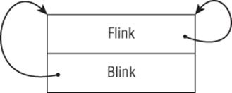
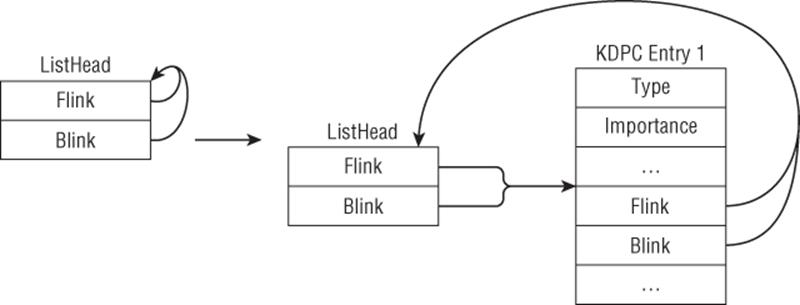
Lists must be initialized with InitializeListHead before usage. This function simply sets the Flink and Blink fields to point to the list head. Its code is shown below and illustrated in Figure 3.4:
VOID InitializeListHead(PLIST_ENTRY ListHead) {
ListHead->Flink = ListHead->Blink = ListHead;
return;
}
Figure 3.4
In assembly form, this would translate to three instructions: one to retrieve ListHead and two to fill out the Flink and Blink pointers. Consider how InitializeListHead manifests itself in x86, x64, and the ARM assembly:
x86
lea eax, [esi+2Ch]
mov [eax+4], eax
mov [eax], eax
x64
lea r11, [rbx+48h]
mov [r11+8], r11
mov [r11], r11
ARM
ADDS.W R3, R4, #0x2C
STR R3, [R3,#4]
STR R3, [R3]
In all three cases, the same pointer and register are used in write-only operations. Another key observation is that the writes at offset +0 and +4/8 from the base register; these offsets correspond to the Flink and Blink pointers in the structure. Whenever you see this code pattern, you should think of lists.
After initializing the list, entries can be inserted at the head or the tail. As mentioned previously, a list entry is simply a LIST_ENTRY inside a larger structure; for example, the kernel KDPC structure (discussed later in the chapter) has a DpcListEntry field:
C Definition
typedef struct _KDPC {
UCHAR Type;
UCHAR Importance;
volatile USHORT Number;
LIST_ENTRY DpcListEntry;
PKDEFERRED_ROUTINE DeferredRoutine;
PVOID DeferredContext;
PVOID SystemArgument1;
PVOID SystemArgument2;
__volatile PVOID DpcData;
} KDPC, *PKDPC, *PRKDPC;
x64
0: kd> dt nt!_KDPC
+0x000 Type : UChar
+0x001 Importance : UChar
+0x002 Number : Uint2B
+0x008 DpcListEntry : _LIST_ENTRY
+0x018 DeferredRoutine : Ptr64 void
+0x020 DeferredContext : Ptr64 Void
+0x028 SystemArgument1 : Ptr64 Void
+0x030 SystemArgument2 : Ptr64 Void
+0x038 DpcData : Ptr64 Void
Suppose you have a list with one KDPC entry, as shown in Figure 3.5.
Figure 3.5
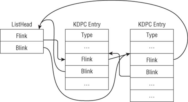
Insertion is done with InsertHeadList and InsertTailList. Consider the insertion of an entry at the head, as shown in Figure 3.6.
Figure 3.6
The source code for these routines and how they may manifest in assembly form are shown here:
Note
These snippets are taken from the kernel function KeInsertQueueDpc on Windows 8, with a couple of lines removed for clarity. The point here is to observe how the new entry is inserted in the list. Instruction scheduling might change the order of some instructions, but they will be mostly the same.
InsertHeadList
C
VOID InsertHeadList(PLIST_ENTRY ListHead, PLIST_ENTRY Entry) {
PLIST_ENTRY Flink;
Flink = ListHead->Flink;
Entry->Flink = Flink;
Entry->Blink = ListHead;
Flink->Blink = Entry;
ListHead->Flink = Entry;
return;
}
ARM
LDR R1, [R5]
STR R5, [R2,#4]
STR R1, [R2]
STR R2, [R1,#4]
STR R2, [R5]
x86
mov edx, [ebx]
mov [ecx], edx
mov [ecx+4], ebx
mov [edx+4], ecx
mov [ebx], ecx
x64
mov rcx, [rdi]
mov [rax+8], rdi
mov [rax], rcx
mov [rcx+8], rax
mov [rdi], rax
InsertTailList
C
VOID InsertTailList(PLIST_ENTRY ListHead, PLIST_ENTRY Entry) {
PLIST_ENTRY Blink;
Blink = ListHead->Blink;
Entry->Flink = ListHead;
Entry->Blink = Blink;
Blink->Flink = Entry;
ListHead->Blink = Entry;
return;
}
ARM
LDR R1, [R5,#4]
STR R5, [R2]
STR R1, [R2,#4]
STR R2, [R1]
STR R2, [R5,#4]
x86
mov ecx, [ebx+4]
mov [eax], ebx
mov [eax+4], ecx
mov [ecx], eax
mov [ebx+4], eax
x64
mov rcx, [rdi+8]
mov [rax], rdi
mov [rax+8], rcx
mov [rcx], rax
mov [rdi+8], rax
In the preceding snippets, R5/EBX/RDI point to ListHead, and R2/ECX/RAX point to Entry.
Removal is done with RemoveHeadList, RemoveTailList, and RemoveEntryList. These routines are typically preceded by the IsListEmpty function, which simply checks whether the list head's Flink points to itself:
IsListEmpty
C
BOOLEAN IsListEmpty(PLIST_ENTRY ListHead) {
return (BOOLEAN)(ListHead->Flink == ListHead);
}
ARM
LDR R2, [R4]
CMP R2, R4
x86
mov eax, [esi]
cmp eax, esi
x64
mov rax, [rbx]
cmp rax, rbx
RemoveHeadList
C
PLIST_ENTRY RemoveHeadList(PLIST_ENTRY ListHead) {
PLIST_ENTRY Flink;
PLIST_ENTRY Entry;
Entry = ListHead->Flink;
Flink = Entry->Flink;
ListHead->Flink = Flink;
Flink->Blink = ListHead;
return Entry;
}
ARM
LDR R2, [R4]
LDR R1, [R2]
STR R1, [R4]
STR R4, [R1,#4]
x86
mov eax, [esi]
mov ecx, [eax]
mov [esi], ecx
mov [ecx+4], esi
x64
mov rax, [rbx]
mov rcx, [rax]
mov [rbx], rcx
mov [rcx+8], rbx
RemoveTailList
C
PLIST_ENTRY RemoveTailList(PLIST_ENTRY ListHead) {
PLIST_ENTRY Blink;
PLIST_ENTRY Entry;
Entry = ListHead->Blink;
Blink = Entry->Blink;
ListHead->Blink = Blink;
Blink->Flink = ListHead;
return Entry;
}
ARM
LDR R6, [R5,#4]
LDR R2, [R6,#4]
STR R2, [R5,#4]
STR R5, [R2]
x86
mov ebx, [edi+4]
mov eax, [ebx+4]
mov [edi+4], eax
mov [eax], edi
x64
mov rsi, [rdi+8]
mov rax, [rsi+8]
mov [rdi+8], rax
mov [rax], rdi
RemoveEntryList
C
BOOLEAN RemoveEntryList(PLIST_ENTRY Entry){
PLIST_ENTRY Blink;
PLIST_ENTRY Flink;
Flink = Entry->Flink;
Blink = Entry->Blink;
Blink->Flink = Flink;
Flink->Blink = Blink;
return (BOOLEAN)(Flink == Blink);
}
ARM
LDR R1,[R0]
LDR R2,[R0,#4]
STR R1,[R2]
STR R2,[R1,#4]
x86
mov edx, [ecx]
mov eax, [ecx+4]
mov [eax], edx
mov [edx+4], eax
x64
mov rdx, [rcx]
mov rax, [rcx+8]
mov [rax], rdx
mov [rdx+8], rax
Note that all list manipulation functions operate solely on the LIST_ENTRY structure. In order to do useful things with a list entry, code needs to manipulate the actual data in the entry. How do programs access fields in a list entry? This is done with the CONTAINING_RECORD macro:
#define CONTAINING_RECORD(address, type, field) ((type *)( \
(PCHAR)(address) - \
(ULONG_PTR)(&((type *)0)->field)))
CONTAINING_RECORD returns the base address of a structure using the following method: It calculates the offset of a field in a structure by casting the structure pointer to 0, then subtracts that from the real address of the field. In practice, this macro usually takes the address of the LIST_ENTRY field in the list entry, the type of the list entry, and the name of that field. For example, suppose you have a list of KDPC entries (see definition earlier) and you want a function to access the DeferredRoutine field; the code would be as follows:
PKDEFERRED_ROUTINE ReadEntryDeferredRoutine (PLIST_ENTRY entry) {
PKDPC p;
p = CONTAINING_RECORD(entry, KDPC, DpcListEntry);
return p->DeferredRoutine;
}
This macro is commonly used immediately after calling one of the list removal routines or during list entry enumeration.
Walk-Through
Having discussed the concepts and implementation details of the list manipulation functions in kernel mode, we will now apply that to the analysis of Sample C. This walk-through has three objectives:
· Show one common usage of lists in a real-life driver/rootkit
· Demonstrate the uncertainties a reverse engineer faces in practice
· Discuss the problems of undocumented structures and hardcoded offsets
This driver does many things, but we are only interested in two functions: sub_11553 and sub_115DA. Consider the following snippet from sub_115DA:
01: .text:000115FF mov eax, dword_1436C
02: .text:00011604 mov edi, ds:wcsncpy
03: .text:0001160A mov ebx, [eax]
04: .text:0001160C mov esi, ebx
05: .text:0001160E loop_begin:
06: .text:0001160E cmp dword ptr [esi+20h], 0
07: .text:00011612 jz short failed
08: .text:00011614 push dword ptr [esi+28h]
09: .text:00011617 call ds:MmIsAddressValid
10: .text:0001161D test al, al
11: .text:0001161F jz short failed
12: .text:00011621 mov eax, [esi+28h]
13: .text:00011624 test eax, eax
14: .text:00011626 jz short failed
15: .text:00011628 movzx ecx, word ptr [esi+24h]
16: .text:0001162C shr ecx, 1
17: .text:0001162E push ecx ; size_t
18: .text:0001162F push eax ; wchar_t *
19: .text:00011630 lea eax, [ebp+var_208]
20: .text:00011636 push eax ; wchar_t *
21: .text:00011637 call edi ; wcsncpy
22: .text:00011639 lea eax, [ebp+var_208]
23: .text:0001163F push eax ; wchar_t *
24: .text:00011640 call ds:_wcslwr
25: .text:00011646 lea eax, [ebp+var_208]
26: .text:0001164C push offset aKrnl ; "krnl"
27: .text:00011651 push eax ; wchar_t *
28: .text:00011652 call ds:wcsstr
29: .text:00011658 add esp, 18h
30: .text:0001165B test eax, eax
31: .text:0001165D jnz short matched_krnl
32: .text:0001165F mov esi, [esi]
33: .text:00011661 cmp esi, ebx
34: .text:00011663 jz short loop_end
35: .text:00011665 jmp short loop_begin
36: .text:00011667 matched_krnl:
37: .text:00011667 lea eax, [ebp+var_208]
38: .text:0001166D push '\' ; wchar_t
39: .text:0001166F push eax ; wchar_t *
40: .text:00011670 call ds:wcsrchr
41: .text:00011676 pop ecx
42: .text:00011677 test eax, eax
Lines 1–4 read a pointer from a global variable at dword_1436C and save it in EBX and ESI. The loop body references this pointer at offset 0x20 and 0x28; therefore, you can deduce that it is a pointer to a structure of at least 0x2c bytes in size. At the end of the loop, it reads another pointer from the structure and compares it against the original pointer (saved in line 3). Note that the pointer is read from offset 0. Hence, at this point, you can surmise that this loop is iterating over a list in which the “next” pointer is at offset 0. Can you claim that this structure contains a LIST_ENTRY field at offset 0? No, there is not enough concrete data at the moment to support that. Let's figure out where the global variable dword_1436C comes from.
sub_11553 uses the STDCALL calling convention and takes two parameters: a pointer to a DRIVER_OBJECT, and a pointer to a global variable dword_1436C. It has the following interesting code snippet:
01: .text:00011578 mov eax, 0FFDFF034h
02: .text:0001157D mov eax, [eax]
03: .text:0001157F mov eax, [eax+70h]
04: …
05: .text:0001159E mov ecx, [ebp+arg_4] ; pointer to the global var
06: .text:000115A1 mov [ecx], eax
Line 2 reads a pointer from a hardcoded address, 0xFFDFF034. On Windows XP, there is a processor control block structure (discussed later in the chapter) at 0xFFDFF000 and offset 0x34 is the KdVersionBlock pointer. Lines 3–6 read a pointer value at offset 0x70 into the KdVersionBlock and write it back to the global variable; you know it is a pointer because it is used to iterate the list entries in sub_115DA. In order to figure out the exact list entry type, you need to determine what is at offset 0x70 of the KdVersionBlock structure. Because this is an undocumented OS-specific structure, you have to either reverse engineer the Windows XP kernel or search the Internet to see if other people already figured it out. The results indicate that on Windows XP, offset 0x70 of the KdVersionBlock structure is a pointer to a global list head called PsLoadedModuleList. Each entry in this list is of typeKLDR_DATA_TABLE_ENTRY and it stores information about currently loaded kernel modules (name, base address, size, etc.); the first member in this structure is of type LIST_ENTRY. This makes sense because we previously deduced that at offset 0 is the “next” pointer (Flink to be precise).
Note
The structure KLDR_DATA_TABLE_ENTRY is undocumented, but it is very similar to LDR_DATA_TABLE_ENTRY, which is in the public symbols. On Windows XP, the FullDllName and BaseDllName fields are at the same offset (0x24 and 0x2c).
Assuming that the information from the Internet is correct, these two functions can be summarized as follows:
· sub_11553 reads the KdVersionBlock pointer from the processor control block and retrieves the pointer to PsLoadedModuleList from there; it saves this pointer to the global variable. PsLoadedModuleList is the head of a list whose list entries are of type KLDR_DATA_TABLE_ENTRY. This function will be given the friendly name GetLoadedModuleList.
· sub_115DA uses the list head pointer to iterate over all entries searching for a module name with the substring "krnl". The code searches for the substring "krnl" because the author is looking for the NT kernel image name (usually “ntoskrnl.exe”). This function will be given the friendly nameGetKernelName.
You can briefly translate them back to C:
typedef struct _KLDR_DATA_TABLE_ENTRY {
LIST_ENTRY ListEntry;
…
UNICODE_STRING FullDllName;
UNICODE_STRING BaseDllName;
…
} KLDR_DATA_TABLE_ENTRY, *PKLDR_DATA_TABLE_ENTRY;
BOOL GetLoadedModuleList(PDRIVER_OBJECT drvobj, PLIST_ENTRY g_modlist)
{
…
g_modlist = (PCR->KdVersionBlock) + 0x70
…
}
BOOL GetKernelName()
{
WCHAR fname[…];
PKLDR_DATA_TABLE_ENTRY entry;
PLIST_ENTRY p = g_modlist->Flink;
while (p != g_modlist)
{
entry = CONTAINING_RECORD(p, KLDR_DATA_TABLE_ENTRY, ListEntry);
…
wcsncpy(fname, entry->FullDllName.Buffer, entry->FullDllName.Length * 2);
…
if (wcsstr(fname, L"krnl") != NULL) { … }
p = p->Flink;
}
…
}
While this driver may seem to work on a specific version of Windows, there are several problems with it. First, it assumes that the PCR is always located at 0xFFDFF000 and that the KdVersionBlock is always at offset 0x34; these assumptions do not hold for Windows Vista+. Second, the driver assumes that KdVersionBlock always contains a valid value; this is untrue because the value is valid only for the first processor's PCR. Hence, if this code were executed on a multi-processor system and the thread happened to be scheduled on another processor, this code would crash. Third, it assumes that there is a UNICODE_STRING at offset 0x24 in the KLDR_DATA_TABLE_ENTRY structure (which is undocumented itself); this may not always be true because Microsoft may add or remove fields from the structure definition, causing the offset to change. Fourth, this code will certainly fail on an x64 kernel because the offsets are all different. Finally, the loaded module list may change (i.e., drivers being unloaded) while the driver is iterating the list; hence, it may receive stale results or lead to an access violation as a result of accessing a module that is no longer there. Also note that the driver does not use any kind of locking mechanism while iterating a global list. As you analyze more kernel-mode rootkits or third-party drivers, you will frequently encounter code written with these premature assumptions.
For this particular sample, you can tell that the developer just wants to get the kernel image name and base address. This could have been easily achieved using the documented kernel API AuxKlibQueryModuleInformation. (See also the exercise on AuxKlibQueryModuleInformation.)
To conclude, we would like to briefly discuss the thinking process in analyzing these two functions. How were we able to go from seemingly random values such as 0xFFDF034, 0x70, and 0x28 to PCR, KdVersionBlock, PsLoadedModuleList, KLDR_DATA_TABLE_ENTRY, and so on? The truth is that we already have previous kernel knowledge and experience analyzing kernel-mode drivers so we instinctively thought about these structures. For example, we started with a loop that processes each list entry looking for the substring "krnl"; we immediately guessed that they are searching for the kernel image name. The string and length offsets (0x24 and 0x28) alerted us of a UNICODE_STRING; with our kernel knowledge, we guessed that this is the KLDR_DATA_TABLE_ENTRY structure and verified that it is indeed the case using public symbols. Next, we know that PsLoadedModuleList is the global list head for the loaded module list. Because PsLoadedModuleList is not an exported symbol, we know that the driver must retrieve this from another structure. Going backwards, we see the hardcoded memory address 0xFFDF034 and immediately think of the PCR. We verify this in the debugger:
0: kd> dt nt!_KPCR 0xffdff000
+0x000 NtTib : _NT_TIB
+0x01c SelfPcr : 0xffdff000 _KPCR
+0x020 Prcb : 0xffdff120 _KPRCB
+0x024 Irql : 0 ''
+0x028 IRR : 0
+0x02c IrrActive : 0
+0x030 IDR : 0xffffffff
+0x034 KdVersionBlock : 0x8054d2b8 Void
…
From experience, we know that KdVersionBlock is a pointer to a large structure storing interesting information such as the kernel base address and list heads. At that point, we have all the information and data structures to understand the code.
As you can see, there is a systematic thinking process behind the analysis; however, it requires a substantial amount of background knowledge about the operating system, and experience. When you are first starting, you may not have all the knowledge and intuition required to quickly understand kernel-mode drivers. Have no fear! This book attempts to provide a strong foundation by explaining all the major kernel concepts and data structures. With a strong foundation and a lot of practice (see the exercises), you will eventually be able to do it with great ease. Remember: foundational knowledge + intuition + experience + patience = skills.
Exercises
1. On Windows 8 x64, the following kernel functions have InitalizeListHead inlined at least once:
· CcAllocateInitializeMbcb
· CmpInitCallbacks
· ExCreateCallback
· ExpInitSystemPhase0
· ExpInitSystemPhase1
· ExpTimerInitialization
· InitBootProcessor
· IoCreateDevice
· IoInitializeIrp
· KeInitThread
· KeInitializeMutex
· KeInitializeProcess
· KeInitializeTimerEx
· KeInitializeTimerTable
· KiInitializeProcessor
· KiInitializeThread
· MiInitializeLoadedModuleList
· MiInitializePrefetchHead
· PspAllocateProcess
· PspAllocateThread
· Identify where InitializeListHead is inlined in these routines.
2. Repeat the previous exercise for InsertHeadList in the following routines:
· CcSetVacbInFreeList
· CmpDoSort
· ExBurnMemory
· ExFreePoolWithTag
· IoPageRead
· IovpCallDriver1
· KeInitThread
· KiInsertQueueApc
· KeInsertQueueDpc
· KiQueueReadyThread
· MiInsertInSystemSpace
· MiUpdateWsle
· ObpInsertCallbackByAltitude
3. Repeat the previous exercise for InsertTailList in the following routines:
· AlpcpCreateClientPort
· AlpcpCreateSection
· AlpcpCreateView
· AuthzBasepAddSecurityAttributeToLists
· CcFlushCachePriv
· CcInitializeCacheManager
· CcInsertVacbArray
· CcSetFileSizesEx
· CmRenameKey
· ExAllocatePoolWithTag
· ExFreePoolWithTag
· ExQueueWorkItem
· ExRegisterCallback
· ExpSetTimer
· IoSetIoCompletionEx2
· KeInsertQueueDpc
· KeStartThread
· KiAddThreadToScbQueue
· KiInsertQueueApc
· KiQueueReadyThread
· MiInsertNewProcess
· PnpRequestDeviceAction
· PspInsertProcess
· PspInsertThread
4. Repeat the previous exercise for RemoveHeadList in the following routines:
· AlpcpFlushResourcesPort
· CcDeleteMbcb
· CcGetVacbMiss
· CmpLazyCommitWorker
· ExAllocatePoolWithTag
· FsRtlNotifyCompleteIrpList
· IopInitializeBootDrivers
· KiProcessDisconnectList
· PnpDeviceCompletionQueueGetCompletedRequest
· RtlDestroyAtomTable
· RtlEmptyAtomTable
· RtlpFreeAllAtom
5. Repeat the previous exercise for RemoveTailList in the following routines:
· BootApplicationPersistentDataProcess
· CmpCallCallBacks
· CmpDelayCloseWorker
· ObpCallPostOperationCallbacks
· RaspAddCacheEntry
6. Repeat the previous exercise for RemoveEntryList in the following routines:
· AlpcSectionDeleteProcedure
· AlpcpDeletePort
· AlpcpUnregisterCompletionListDatabase
· AuthzBasepRemoveSecurityAttributeFromLists
· CcDeleteBcbs
· CcFindNextWorkQueueEntry
· CcLazyWriteScan
· CcSetFileSizesEx
· CmShutdownSystem
· CmUnRegisterCallback
· CmpCallCallBacks
· CmpPostApc
· ExFreePoolWithTag
· ExQueueWorkItem
· ExTimerRundown
· ExpDeleteTimer
· ExpSetTimer
· IoDeleteDevice
· IoUnregisterFsRegistrationChange
· IopfCompleteRequest
· KeDeregisterBugCheckCallback
· KeDeregisterObjectNotification
· KeRegisterObjectNotification
· KeRemoveQueueApc
· KeRemoveQueueDpc
· KiCancelTimer
· KeTerminateThread
· KiDeliverApc
· KiExecuteAllDpcs
· KiExpireTimerTable
· KiFindReadyThread
· KiFlushQueueApc
· KiInsertTimerTable
· KiProcessExpiredTimerList
· MiDeleteVirtualAddresses
· NtNotifyChangeMultipleKeys
· ObRegisterCallbacks
· ObUnRegisterCallbacks
7. Repeat the previous exercises on Windows 8 x86/ARM and Windows 7 x86/x64. What were the differences (if any)?
8. If you did the exercises for InsertHeadList, InsertTailList, RemoveHeadList, RemoveTailList, and RemoveEntryList on Windows 8, you should have observed a code construct common to all these functions. This construct should also enable you to easily spot the inlined list insertion and removal routines. Explain this code construct and why it is there. Hint: This construct exists only on Windows 8 and it requires you to look at the IDT.
9. In the walk-through, we mentioned that a driver can enumerate all loaded modules with the documented API AuxKlibQueryModuleInformation. Does this API guarantee that the returned module list is always up-to-date? Explain your answer. Next, reverse engineerAuxKlibQueryModuleInformation on Windows 8 and explain how it works. How does it handle the case when multiple threads are requesting access to the loaded module list? Note: The internal function handling this request (and others) is fairly large, so you will need some patience. Alternatively, you can use a debugger to help you trace the interesting code.
10. Explain how the following functions work: KeInsertQueueDpc, KiRetireDpcList, KiExecuteDpc, and KiExecuteAllDpcs. If you feel like an overachiever, decompile those functions from the x86 and x64 assemblies and explain the differences.
Asynchronous and Ad-Hoc Execution
During the lifetime of a driver, it may create system threads, register callbacks for certain events, queue a function to be executed in the future, and so on. This section covers a variety of mechanisms a driver can use to achieve these forms of asynchronous and ad-hoc execution. The mechanisms covered include system threads, work items, APCs, DPCs, timers, and process and thread callbacks.
System Threads
A typical user-mode program may have multiple threads handling different requests. Similarly, a driver may create multiple threads to handle requests from the kernel or user. These threads can be created with the PsCreateSystemThread API:
NTSTATUS PsCreateSystemThread(
_Out_ PHANDLE ThreadHandle,
_In_ ULONG DesiredAccess,
_In_opt_ POBJECT_ATTRIBUTES ObjectAttributes,
_In_opt_ HANDLE ProcessHandle,
_Out_opt_ PCLIENT_ID ClientId,
_In_ PKSTART_ROUTINE StartRoutine,
_In_opt_ PVOID StartContext
);
If called with a NULL ProcessHandle parameter, this API will create a new thread in the System process and set its start routine to StartRoutine. The usage of system threads varies according to driver requirement. For example, the driver may decide to create a thread during initialization to handle subsequent I/O requests or wait on some events. One concrete example is the kernel creating a system thread to process DPCs (see also the KiStartDpcThread function).
Exercises
1. After reading some online forums, you notice some people suggesting that PsCreateSystemThread will create a thread in the context of the calling process. In other words, they are suggesting that if you call PsCreateSystemThread in an IOCTL handler, the new thread will be in the context of the requesting user-mode application. Assess the validity of this statement by writing a driver that calls PsCreateSystemThread in the IOCTL handler. Next, experiment with a non-NULL ProcessHandle and determine if the context differs.
2. Cross-reference as many calls to PsCreateSystemThread as possible in the kernel image. Determine whether any of them pass a non-NULL ProcessHandle parameter. Explain the purpose of these routines. Repeat the exercise for as many functions as possible.
Work Items
Work items are similar to system threads except that no physical thread objects are created for them. A work item is simply an object in a queue processed by a pool of system threads. Concretely speaking, a work item is a structure defined as follows:
0: kd> dt nt!_IO_WORKITEM
+0x000 WorkItem : _WORK_QUEUE_ITEM
+0x020 Routine : Ptr64 void
+0x028 IoObject : Ptr64 Void
+0x030 Context : Ptr64 Void
+0x038 Type : Uint4B
+0x03c ActivityId : _GUID
0: kd> dt nt!_WORK_QUEUE_ITEM
+0x000 List : _LIST_ENTRY
+0x010 WorkerRoutine : Ptr64 void
+0x018 Parameter : Ptr64 Void
Note that its WorkItem field is actually a list entry containing the worker routine and parameter. This entry will eventually be inserted into a queue later. A driver calls the function IoAllocateWorkItem to get back a pointer to an IO_WORKITEM allocated in non-paged pool. Next, the driver initializes and queues the work item by calling IoQueueWorkItem:
PIO_WORKITEM IoAllocateWorkItem(
_In_ PDEVICE_OBJECT DeviceObject
);
VOID IoQueueWorkItem(
_In_ PIO_WORKITEM IoWorkItem,
_In_ PIO_WORKITEM_ROUTINE WorkerRoutine,
_In_ WORK_QUEUE_TYPE QueueType,
_In_opt_ PVOID Context
);
The initialization part simply fills in the worker routine, parameter/context, and queue priority/type:
IO_WORKITEM_ROUTINE WorkItem;
VOID WorkItem(
_In_ PDEVICE_OBJECT DeviceObject,
_In_opt_ PVOID Context
)
{ … }
typedef enum _WORK_QUEUE_TYPE {
CriticalWorkQueue = 0,
DelayedWorkQueue = 1,
HyperCriticalWorkQueue = 2,
MaximumWorkQueue = 3
} WORK_QUEUE_TYPE;
Where is it queued? As explained earlier, each processor has an associated KPRCB that contains a field called ParentNode, which is a pointer to a KNODE structure; when the processor is initialized, this pointer points to an ENODE structure that holds the work items queue:
Work items queue
0: kd> dt nt!_KPRCB
…
+0x5338 ParentNode : Ptr64 _KNODE
0: kd> dt nt!_KNODE
+0x000 DeepIdleSet : Uint8B
+0x040 ProximityId : Uint4B
+0x044 NodeNumber : Uint2B
0: kd> dt nt!_ENODE
+0x000 Ncb : _KNODE
+0x0c0 ExWorkerQueues : [7] _EX_WORK_QUEUE
+0x2f0 ExpThreadSetManagerEvent : _KEVENT
+0x308 ExpWorkerThreadBalanceManagerPtr : Ptr64 _ETHREAD
+0x310 ExpWorkerSeed : Uint4B
+0x314 ExWorkerFullInit : Pos 0, 1 Bit
+0x314 ExWorkerStructInit : Pos 1, 1 Bit
+0x314 ExWorkerFlags : Uint4B
0: kd> dt nt!_EX_WORK_QUEUE
+0x000 WorkerQueue : _KQUEUE
+0x040 WorkItemsProcessed : Uint4B
+0x044 WorkItemsProcessedLastPass : Uint4B
+0x048 ThreadCount : Int4B
+0x04c TryFailed : UChar
ExQueueWorkItemEx
ExQueueWorkItemEx proc near
…
mov rax, gs:20h
mov r8, [rax+5338h] ; enode
movzx eax, word ptr [r8+44h]
mov ecx, eax
lea rax, [rax+rax*2]
shl rax, 6
add rax, rbp
…
mov edx, r9d ; queue type
mov rcx, r11 ; workitem passed in
call ExpQueueWorkItemNode
What actually happens is that each processor has several queues to store the work items and there is a system thread dequeueing one item at a time for execution. This system thread responsible for dequeueing is ExpWorkerThread.
As previously explained, work items are lightweight because they do not require new thread objects to be created. They also have two important properties:
· They are executed in the context of the System process. The reason is because the ExpWorkerThread runs in the System process.
· They are executed at PASSIVE_LEVEL.
Due to their lightweight nature, it is a common driver programming pattern to queue work items inside a DPC.
Exercises
1. Explain how we were able to determine that ExpWorkerThread is the system thread responsible for dequeueing work items and executing them. Hint: The fastest way is to write a driver.
2. Explore IoAllocateWorkItem, IoInitializeWorkItem, IoQueueWorkItem, IopQueueWorkItemProlog, and ExQueueWorkItem, and explain how they work.
3. Work items and system threads (i.e., those created by PsCreateSystemThread) are mostly identical in terms of functionality, so explain why DPCs frequently queue work items to handle requests but never call PsCreateSystemThread.
4. Write a driver to enumerate all work items on the system and explain the problems you had to overcome in the process.
Asynchronous Procedure Calls
Asynchronous procedure calls (APCs) are used to implement many important operations such as asynchronous I/O completion, thread suspension, and process shutdown. Unfortunately, they are undocumented from a kernel perspective. The official driver development documentation simply includes a short section acknowledging that APCs exist and that there are different types. However, for common reverse engineering tasks, it is not necessary to understand all the underlying details. This section explains what APCs are and how they are commonly used.
APC Fundamentals
Generally speaking, APCs are functions that execute in a particular thread context. They can be divided into two types: kernel-mode and user-mode. Kernel-mode APCs can be either normal or special; normal ones execute at PASSIVE_LEVEL, whereas special ones execute at APC_LEVEL (both execute in kernel mode). User APCs execute at PASSIVE_LEVEL in user mode when the thread is in an alertable state. Because APCs run in thread context, they are always associated with an ETHREAD object.
Concretely speaking, an APC is defined by the KAPC structure:
1: kd> dt nt!_KAPC
+0x000 Type : UChar
+0x001 SpareByte0 : UChar
+0x002 Size : UChar
+0x003 SpareByte1 : UChar
+0x004 SpareLong0 : Uint4B
+0x008 Thread : Ptr32 _KTHREAD
+0x00c ApcListEntry : _LIST_ENTRY
+0x014 KernelRoutine : Ptr32 void
+0x018 RundownRoutine : Ptr32 void
+0x01c NormalRoutine : Ptr32 void
+0x014 Reserved : [3] Ptr32 Void
+0x020 NormalContext : Ptr32 Void
+0x024 SystemArgument1 : Ptr32 Void
+0x028 SystemArgument2 : Ptr32 Void
+0x02c ApcStateIndex : Char
+0x02d ApcMode : Char
+0x02e Inserted : UChar
This structured is initialized by the KeInitializeApc API:
KeInitializeApc
NTKERNELAPI VOID KeInitializeApc(
PKAPC Apc,
PKTHREAD Thread,
KAPC_ENVIRONMENT Environment,
PKKERNEL_ROUTINE KernelRoutine,
PKRUNDOWN_ROUTINE RundownRoutine,
PKNORMAL_ROUTINE NormalRoutine,
KPROCESSOR_MODE ProcessorMode,
PVOID NormalContext
);
NTKERNELAPI BOOLEAN KeInsertQueueApc(
PRKAPC Apc,
PVOID SystemArgument1,
PVOID SystemArgument2,
KPRIORITY Increment
);
Callback prototypes
typedef VOID (*PKKERNEL_ROUTINE)(
PKAPC Apc,
PKNORMAL_ROUTINE *NormalRoutine,
PVOID *NormalContext,
PVOID *SystemArgument1,
PVOID *SystemArgument2
);
typedef VOID (*PKRUNDOWN_ROUTINE)(
PKAPC Apc
);
typedef VOID (*PKNORMAL_ROUTINE)(
PVOID NormalContext,
PVOID SystemArgument1,
PVOID SystemArgument2
);
typedef enum _KAPC_ENVIRONMENT {
OriginalApcEnvironment,
AttachedApcEnvironment,
CurrentApcEnvironment,
InsertApcEnvironment
} KAPC_ENVIRONMENT, *PKAPC_ENVIRONMENT;
Note
This definition is taken from http://forum.sysinternals.com/howto-capture-kernel-stack-traces_topic19356.html. While we cannot guarantee its correctness, it has been known to work in experiments.
Apc is a caller-allocated buffer of type KAPC. In practice, it is usually allocated in non-paged pool by ExAllocatePool and freed in the kernel or normal routine. Thread is the thread to which this APC should be queued. Environment determines the environment in which the APC executes; for example, OriginalApcEnvironment means that the APC will run in the thread's process context (if it does not attach to another process). KernelRoutine is a function that will be executed at APC_LEVEL in kernel mode; RundownRoutine is a function that will be executed when the thread is terminating; and NormalRoutine is a function that will be executed at PASSIVE_LEVEL in ProcessorMode. User-mode APCs are those that have a NormalRoutine and ProcessorMode set to UserMode. NormalContext is the parameter passed to the NormalRoutine.
Once initialized, an APC is queued with the KeInsertQueueApc API. Apc is the APC initialized by KeInitializeApc. SystemArgument1 and SystemArgument2 are optional arguments that can be passed to kernel and normal routines. Increment is the number to increment the run-time priority; it is similar to the PriorityBoost parameter in IoCompleteRequest. Where is the APC queued? Recall that APCs are always associated with a thread. The KTHREAD structure has two APC queues:
0: kd> dt nt!_KTHREAD
+0x000 Header : _DISPATCHER_HEADER
+0x018 SListFaultAddress : Ptr64 Void
+0x020 QuantumTarget : Uint8B
…
+0x090 TrapFrame : Ptr64 _KTRAP_FRAME
+0x098 ApcState : _KAPC_STATE
+0x098 ApcStateFill : [43] UChar
+0x0c3 Priority : Char
+0x288 SchedulerApc : _KAPC
…
+0x2e0 SuspendEvent : _KEVENT
0: kd> dt nt!_KAPC_STATE
+0x000 ApcListHead : [2] _LIST_ENTRY
+0x020 Process : Ptr64 _KPROCESS
+0x028 KernelApcInProgress : UChar
+0x029 KernelApcPending : UChar
+0x02a UserApcPending : UChar
The ApcState field contains an array of two queues, storing kernel-mode and user-mode APCs, respectively.
Implementing Thread Suspension with APCs
When a program wants to suspend a thread, the kernel queues a kernel APC to the thread. This suspension APC is the SchedulerApc field in the KTHREAD structure; it is initialized in KeInitThread with KiSchedulerApc as the normal routine. KiSchedulerApc simply holds on the thread's SuspendEvent. When the program wants to resume the thread, KeResumeThread releases this event.
Unless you are reverse engineering the Windows kernel or kernel-mode rootkits, it is unlikely that you will run into code using APCs. This is primarily because they are undocumented and hence not commonly used in commercial drivers. However, APCs are frequently used in rootkits because they offer a clean way to inject code into user mode from kernel mode. Rootkits achieve this by queueing a user-mode APC to a thread in the process in which they want to inject code.
Exercises
1. Write a driver using both kernel-mode and user-mode APCs.
2. Write a driver that enumerates all user-mode and kernel-mode APCs for all threads in a process. Hint: You need to take into consideration IRQL level when performing the enumeration.
3. The kernel function KeSuspendThread is responsible for suspending a thread. Earlier you learned that APCs are involved in thread suspension in Windows 8. Explain how this function works and how APCs are used to implement the functionality on Windows 7. What is different from Windows 8?
4. APCs are also used in process shutdown. The KTHREAD object has a flag called ApcQueueable that determines whether an APC may be queued to it. What happens when you disable APC queueing for a thread? Experiment with this by starting up notepad.exe and then manually disable APC queueing to one of its threads (use the kernel debugger to do this).
5. Explain what the following functions do:
· KiInsertQueueApc
· PsExitSpecialApc
· PspExitApcRundown
· PspExitNormalApc
· PspQueueApcSpecialApc
· KiDeliverApc
6. Explain how the function KeEnumerateQueueApc works and then recover its prototype. Note: This function is available only on Windows 8.
7. Explain how the kernel dispatches APCs. Write a driver that uses the different kinds of APCs and view the stack when they are executed. Note: We used the same method to figure out how the kernel dispatches work items.
Deferred Procedure Calls
Deferred procedure calls (DPCs) are routines executed at DISPATCH_LEVEL in arbitrary thread context on a particular processor. Hardware drivers use them to process interrupts coming from the device. A typical usage pattern is for the interrupt service routine (ISR) to queue a DPC, which in turn queues a work item to do the processing.
Hardware drivers do this because the ISR usually runs at high IRQLs (above DISPATCH_LEVEL) and if it takes too long, it could reduce the system's overall performance. Hence, the ISR typically queues a DPC and immediately returns so that the system can process other interrupts. Software drivers can use DPCs to quickly execute short tasks.
Internally, a DPC is defined by the KDPC structure:
0: kd> dt nt!_KDPC
+0x000 Type : UChar
+0x001 Importance : UChar
+0x002 Number : Uint2B
+0x008 DpcListEntry : _LIST_ENTRY
+0x018 DeferredRoutine : Ptr64 void
+0x020 DeferredContext : Ptr64 Void
+0x028 SystemArgument1 : Ptr64 Void
+0x030 SystemArgument2 : Ptr64 Void
+0x038 DpcData : Ptr64 Void
Each field's semantic is as follows:
· Type—Object type. It indicates the kernel object type for this object (i.e., process, thread, timer, DPC, events, etc.). Recall that kernel objects are defined by the nt!_KOBJECTS enumeration. In this case, you are dealing with DPCs, for which there are two types: normal and threaded.
· Importance—DPC importance. It determines where this DPC entry should be in the DPC queue. See also KeSetImportanceDpc.
· Number—Processor number on which the DPC should be queued and executed. See also KeSetTargetProcessorDpc.
· DpcListEntry—LIST_ENTRY for the DPC entry. Internally, the insertion/removal of DPCs from the DPC queue operate on this field. See KeInsertQueueDpc.
· DeferredRoutine—The function associated with this DPC. It will be executed in arbitrary thread context and at DISPATCH_LEVEL. It is defined as follows:
KDEFERRED_ROUTINE CustomDpc;
VOID CustomDpc(
_In_ struct _KDPC *Dpc,
_In_opt_ PVOID DeferredContext,
_In_opt_ PVOID SystemArgument1,
_In_opt_ PVOID SystemArgument2
)
{ … }
· DeferredContext—Parameter to pass to the DPC function.
· SystemArgument1—Custom data to store in the DPC.
· SystemArgument2— Custom data to store in the DPC.
DpcData—A pointer to a KDPC_DATA structure:
0: kd> dt nt!_KDPC_DATA
+0x000 DpcListHead : _LIST_ENTRY
+0x010 DpcLock : Uint8B
+0x018 DpcQueueDepth : Int4B
+0x01c DpcCount : Uint4B
As you can see, it keeps accounting information about DPCs. The data is stored in the DpcData field of the KPRCB structure associated with the DPC. DpcListHead is the head entry in the DPC queue (it is set during KPRCB initialization) and DpcLock is the spinlock protecting this structure; each time a DPC is queued, the DpcCount and DpcQueueDepth are incremented by one. See also KeInsertQueueDpc. It can be instructive to analyze KeInsertQueueDpc in assembly; pay attention to the KPRCB access and head/tail list insertion.
The DPC usage pattern in code is simple: Initialize the KDPC object with KeInitializeDpc and queue it with KeInsertQueueDpc. When the processor IRQL drops to DISPATCH_LEVEL, the kernel processes all DPCs in that queue.
As mentioned earlier, each CPU core keeps its own queue of DPCs. This queue is tracked by the per-core KPRCB structure:
0: kd> dt nt!_KPRCB
+0x000 MxCsr : Uint4B
+0x004 LegacyNumber : UChar
+0x005 ReservedMustBeZero : UChar
+0x006 InterruptRequest : UChar
…
+0x2d80 DpcData : [2] _KDPC_DATA
+0x2dc0 DpcStack : Ptr64 Void
+0x2dc8 MaximumDpcQueueDepth : Int4B
+0x2dcc DpcRequestRate : Uint4B
+0x2dd0 MinimumDpcRate : Uint4B
+0x2dd4 DpcLastCount : Uint4B
+0x2dd8 ThreadDpcEnable : UChar
+0x2dd9 QuantumEnd : UChar
+0x2dda DpcRoutineActive : UChar
0: kd> dt nt!_KDPC_DATA
+0x000 DpcListHead : _LIST_ENTRY
+0x010 DpcLock : Uint8B
+0x018 DpcQueueDepth : Int4B
+0x01c DpcCount : Uint4B
The two notable fields are DpcData and DpcStack. DpcData is an array of KDPC_DATA structures whereby each element tracks a DPC queue; the first element tracks normal DPCs and the second tracks threaded DPCs. The function KeInsertQueueDpc simply inserts the DPC into one of these two queues. The relationship can be illustrated as shown in Figure 3.7.
Figure 3.7
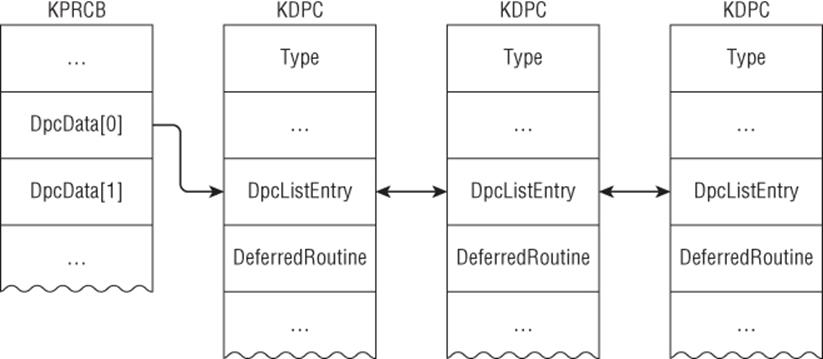
DpcStack is a pointer to a block of memory to be used as the DPC routine's stack.
Windows has several mechanisms to process the DPC queue. The first mechanism is through KiIdleLoop. While “idling,” it checks the PRCB to determine if DPCs are waiting and if so to call KiRetireDpcList to process all DPCs. This is why sometimes these two functions appear on the stack while executing a DPC. For example:
0: kd> kn
# Child-SP RetAddr Call Site
00 fffff800'00b9cc88 fffff800'028db5dc USBPORT!USBPORT_IsrDpc
01 fffff800'00b9cc90 fffff800'028d86fa nt!KiRetireDpcList+0x1bc
02 fffff800'00b9cd40 00000000'00000000 nt!KiIdleLoop+0x5a
The second mechanism occurs when the CPU is at DISPATCH_LEVEL. Consider the following stack:
0: kd> kn
# Child-SP RetAddr Call Site
00 fffff800'00ba2ef8 fffff800'028db5dc USBPORT!USBPORT_IsrDpc
01 fffff800'00ba2f00 fffff800'028d6065 nt!KiRetireDpcList+0x1bc
02 fffff800'00ba2fb0 fffff800'028d5e7c nt!KyRetireDpcList+0x5
03 fffff880'04ac67a0 fffff800'0291b793 nt!KiDispatchInterruptContinue
04 fffff880'04ac67d0 fffff800'028cbda2 nt!KiDpcInterruptBypass+0x13
05 fffff880'04ac67e0 fffff960'0002992c nt!KiInterruptDispatch+0x212
06 fffff880'04ac6978 fffff960'000363b3 win32k!vAlphaPerPixelOnly+0x7c
07 fffff880'04ac6980 fffff960'00035fa4 win32k!AlphaScanLineBlend+0x303
08 fffff880'04ac6a40 fffff960'001fd4f9 win32k!EngAlphaBlend+0x4f4
09 fffff880'04ac6cf0 fffff960'001fdbaa win32k!NtGdiUpdateTransform+0x112d
0a fffff880'04ac6db0 fffff960'001fdd19 win32k!NtGdiUpdateTransform+0x17de
0b fffff880'04ac6ed0 fffff960'001fded8 win32k!EngNineGrid+0xb1
0c fffff880'04ac6f70 fffff960'001fe395 win32k!EngDrawStream+0x1a0
0d fffff880'04ac7020 fffff960'001fece7 win32k!NtGdiDrawStreamInternal+0x47d
0e fffff880'04ac70d0 fffff960'0021a480 win32k!GreDrawStream+0x917
0f fffff880'04ac72c0 fffff800'028cf153 win32k!NtGdiDrawStream+0x9c
10 fffff880'04ac7420 000007fe'fd762cda nt!KiSystemServiceCopyEnd+0x13
This long stack indicates that win32k.sys was handling some graphics operation request from the user, and then the USB port driver's DPC routine—which has nothing to do with win32k—is executed. What probably happened is that while win32k.sys was handling the request, a device interrupt occurred that caused the CPU to operate at device IRQL; and then the IRQL is eventually lowered to DISPATCH_LEVEL, which causes the DPC queue to be processed.
The third mechanism is through a system thread created during processor initialization. KiStartDpcThread creates a thread (KiExecuteDpc) for each processor, which processes the DPC queue whenever it runs. For example:
0: kd> kn
# Child-SP RetAddr Call Site
00 fffff880'03116be8 fffff800'028aadb0 nt!KiDpcWatchdog
01 fffff880'03116bf0 fffff800'028aac4b nt!KiExecuteAllDpcs+0x148
02 fffff880'03116cb0 fffff800'02b73166 nt!KiExecuteDpc+0xcb
03 fffff880'03116d00 fffff800'028ae486 nt!PspSystemThreadStartup+0x5a
04 fffff880'03116d40 00000000'00000000 nt!KiStartSystemThread+0x16
Recall that the thread dispatcher runs at DISPATCH_LEVEL, and code running at this IRQL cannot be interrupted by other software IRQLs (i.e., those below DISPATCH_LEVEL). In other words, if there is an infinite loop in the DPC routine, the processor associated with it will spin forever and the system will practically “freeze”; in a multi-processor system, it may not freeze but the processor executing the DPC will not be usable by the thread dispatcher. In addition, the DPC routine cannot wait on any kind of dispatcher objects because the dispatcher itself operates at DISPATCH_LEVEL; this is why functions such as KeWaitForSingleObject and KeDelayExecutionThread cannot be called in DPC routines.
Note
Windows has a DPC watchdog routine that detects DPCs running over a certain time period and bugchecks with code DPC_WATCHDOG_VIOLATION (0x133). You can query the watchdog timer value by calling KeQueryDpcWatchdogInformation.
Some rootkits use DPCs to synchronize access to global linked lists. For example, they may remove an entry from the ActiveProcessLinks list to hide processes; because this list can be modified at any time by any processor, some rootkit authors use a DPC along with another synchronization mechanism to safely operate on it. In one of the exercises, you will be asked to explain why some authors succeed at this while others fail (machine bugchecks).
Exercises
1. Where and when is the DpcData field in KPRCB initialized?
2. Write a driver to enumerate all DPCs on the entire system. Make sure you support multi-processor systems! Explain the difficulties and how you solved them.
3. Explain how the KiDpcWatchdog routine works.
Timers
Timers are used to signal the expiration of a certain amount of time, which can be periodically or at some time in the future. Optionally, the timer can also be associated with a DPC. For example, if a driver wants to check the status of a device every five minutes or execute a routine 10 minutes in the future, it can achieve this by using timers.
Concretely speaking, a timer is defined by the KTIMER structure:
Timer-related structures
0: kd> dt nt!_KPRCB
…
+0x2dfc InterruptRate : Uint4B
+0x2e00 TimerTable : _KTIMER_TABLE
0: kd> dt nt!_KTIMER_TABLE
+0x000 TimerExpiry : [64] Ptr64 _KTIMER
+0x200 TimerEntries : [256] _KTIMER_TABLE_ENTRY
0: kd> dt nt!_KTIMER
+0x000 Header : _DISPATCHER_HEADER
+0x018 DueTime : _ULARGE_INTEGER
+0x020 TimerListEntry : _LIST_ENTRY
+0x030 Dpc : Ptr64 _KDPC
+0x038 Processor : Uint4B
+0x03c Period : Uint4B
0: kd> dt nt!_KTIMER_TABLE_ENTRY
+0x000 Lock : Uint8B
+0x008 Entry : _LIST_ENTRY
+0x018 Time : _ULARGE_INTEGER
Timer-related routines
VOID KeInitializeTimer(
_Out_ PKTIMER Timer
);
BOOLEAN KeSetTimer(
_Inout_ PKTIMER Timer,
_In_ LARGE_INTEGER DueTime,
_In_opt_ PKDPC Dpc
);
BOOLEAN KeSetTimerEx(
_Inout_ PKTIMER Timer,
_In_ LARGE_INTEGER DueTime,
_In_ LONG Period,
_In_opt_ PKDPC Dpc
);
It is initialized by calling KeInitializeTimer, which simply fills out some of the basic fields. After initialization, the timer can be set through either KeSetTimer or KeSetTimerEx. The difference between the two is that KeSetTimerEx can be used to set a recurring timer (i.e., expire every X time unit). Note that these functions can optionally take a DPC object, which is executed when the timer expires. When calling these routines, the timer is inserted into a timer table in the PRCB (TimerTable->TimerListEntry). Once set and queued, a timer may be cancelled and hence removed from the timer table. This is done by the KeCancelTimer API.
How does the system know when a timer expires? On every clock interrupt, the system updates its runtime and checks the timer list to see if there are any expiring entries; if there are, it requests a DPC interrupt that will process the entries. Hence, timers are also processed at DISPATCH_LEVEL.
There are many examples showing how timers are used in the operating system. For example, the system has a periodic timer that synchronizes the system time and checks if the license is expiring (see ExpTimeRefreshDpcRoutine). There is even a timer that expires at the end of a century (seeExpCenturyDpcRoutine).
Exercises
1. Write a driver to enumerate the loaded module list every 10 minutes.
2. Write a driver to enumerate all timers on the system. Make sure you support multi-core systems. Explain why the DPC data associated with the timer does not seem to make sense.
3. Explain the DpcWatchDogTimer field in the PRCB.
4. Write a driver that sets a timer with an associated DPC. Explain the sequence of calls leading to DPC execution. You may be interested in the following functions: KeUpdateRuntime, KeAccumulateTicks, KiTimerExpiration, KiRetireDpcList, and KiExpireTimerTable.
5. Explain how timer insertion works. You will need to look at the function KiInsertTimerTable.
Process and Thread Callbacks
A driver can register callbacks for a variety of events. Two of the most common callbacks are related to processes and threads, and they can be registered through documented APIs such as PsSetCreateProcessNotifyRoutine, PsSetCreateThreadNotifyRoutine, and PsSetLoadImageNotifyRoutine. How do they work?
During system initialization, the kernel calls the function PspInitializeCallbacks to initialize three global arrays: PspCreateThreadNotifyRoutine, PspCreateProcessNotifyRoutine, and PspLoadImageNotifyRoutine. When the driver registers a process, thread, or image callback, it is stored in one of these arrays. In addition, there is a global flag, PspNotifyEnableMask, which determines what notification types are enabled/disabled. In the thread initialization and termination paths (PspInsertThread and PspExitThread, respectively), it checks whether the PspNotifyEnableMask flag is present and invokes the callbacks accordingly.
These callbacks are primarily provided for drivers and hence are not explicitly used by the kernel. For example, many anti-virus software products register these callbacks to monitor system behavior. Kernel-mode rootkits sometimes use them in conjunction with APCs to inject code into new processes.
Exercises
1. This section provided a general explanation of how process, thread, and image notify callbacks are implemented. Investigate the following functions and explain how they work:
· PsSetCreateThreadNotifyRoutine
· PsSetCreateProcessNotifyRoutine
· PsSetLoadImageNotifyRoutine
· PspInitializeCallbacks
2. If you did exercise 1, write a driver that enumerates all process, thread, and image notify routines on the system and remove them.
3. If you did exercise 1, explain two major weaknesses of these notification callbacks. For example, can you create new processes/threads without being detected by these callbacks? Implement your idea and evaluate its effectiveness. Note: It is possible.
4. If you register an image load callback with PsSetLoadImageNotifyRoutine, under what condition is it called? Identify one weakness and implement your idea. Hint: You may need to consult the PE specification.
5. The PsSetCreateThreadNotifyRoutine, PsSetCreateProcessNotifyRoutine, and PsSetLoadImageNotifyRoutine APIs are exposed by the process manager. However, the object and configuration managers also expose their own callbacks through ObRegisterCallbacks andCmRegisterCallback, respectively. Investigate how these callbacks are implemented.
6. Identify other similar callbacks documented in the WDK and investigate how they work (processor, memory, and so on).
Completion Routines
The Windows I/O model is that of a device stack, whereby devices are layered on top of each other, with each layer implementing some specific function. This means that higher-level drivers can pass requests to lower ones for processing. Whichever layer completes the requests marks it done by calling IoCompleteRequest. Completion routines are used to notify drivers that their I/O request has been completed (or that it was cancelled or failed). They run in arbitrary thread context and can be set through the IoSetCompletionRoutine/Ex APIs. IoSetCompletionRoutine is documented in WDK, but it will never appear in an assembly listing or import table because it is forced-inline; one method to identify the IoSetCompletion routine is to see the CompletionRoutine field in an IO_STACK_LOCATION (see the next section) modified:
Structure definition
0: kd> dt nt!_IO_STACK_LOCATION
+0x000 MajorFunction : UChar
+0x001 MinorFunction : UChar
+0x002 Flags : UChar
+0x003 Control : UChar
+0x008 Parameters : <unnamed-tag>
+0x028 DeviceObject : Ptr64 _DEVICE_OBJECT
+0x030 FileObject : Ptr64 _FILE_OBJECT
+0x038 CompletionRoutine : Ptr64 long
+0x040 Context : Ptr64 Void
Function definition
VOID
IoSetCompletionRoutine(
_In_ PIRP Irp,
_In_opt_ PIO_COMPLETION_ROUTINE CompletionRoutine,
_In_opt_ __drv_aliasesMem PVOID Context,
_In_ BOOLEAN InvokeOnSuccess,
_In_ BOOLEAN InvokeOnError,
_In_ BOOLEAN InvokeOnCancel
)
{
PIO_STACK_LOCATION irpSp;
irpSp = IoGetNextIrpStackLocation(Irp);
irpSp->CompletionRoutine = CompletionRoutine;
irpSp->Context = Context;
irpSp->Control = 0;
if (InvokeOnSuccess) {
irpSp->Control = SL_INVOKE_ON_SUCCESS;
}
if (InvokeOnError) {
irpSp->Control |= SL_INVOKE_ON_ERROR;
}
if (InvokeOnCancel) {
irpSp->Control |= SL_INVOKE_ON_CANCEL;
}
}
The I/O manager calls the registered completion routine as part of IopfCompleteRequest.
Although the legitimate use of completion routines is obvious, rootkits may use them for nefarious purposes. For example, they can set a completion routine to modify the return buffer from a lower driver before it is returned to user mode.
Exercise
1. Write a test driver using a completion routine and determine where it is called from.
I/O Request Packets
Windows uses I/O request packets (IRPs) to describe I/O requests to kernel-mode components (like drivers). When a user-mode application calls an API to request data, the I/O manager builds an IRP to describe the request and determines which device to send the IRP to for processing. From the time an IRP is created until its completion by a driver, it may have passed through multiple devices, and additional IRPs could have been created to fulfill the request. One can think of IRPs as the fundamental unit of communication between devices for I/O requests. An IRP is defined in WDK headers by the partially opaque IRP structure, but most fields are undocumented (hence partially opaque):
0: kd> dt nt!_IRP
+0x000 Type : Int2B
…
+0x042 StackCount : Char
+0x043 CurrentLocation : Char
…
+0x058 Overlay : <unnamed-tag>
+0x068 CancelRoutine : Ptr64 void
+0x070 UserBuffer : Ptr64 Void
+0x078 Tail : <unnamed-tag>
From a programming perspective, an IRP can be divided into two areas: static and dynamic. The static part is an IRP structure with basic information about the request such as who requested the operation (kernel or user), requesting thread, and data passed in from the user. The Overlay and Tailfields are unions containing metadata about the request. The dynamic part is immediately after the header; it is an array of IO_STACK_LOCATION structures containing device-specific request information. An IO_STACK_LOCATION contains the IRP's major and minor function, parameters for the request, and an optional completion routine. Similar to IRP, it is a partially opaque structure:
0: kd> dt nt!_IO_STACK_LOCATION
+0x000 MajorFunction : UChar
+0x001 MinorFunction : UChar
+0x002 Flags : UChar
+0x003 Control : UChar
+0x008 Parameters : <unnamed-tag>
+0x028 DeviceObject : Ptr64 _DEVICE_OBJECT
+0x030 FileObject : Ptr64 _FILE_OBJECT
+0x038 CompletionRoutine : Ptr64 long
+0x040 Context : Ptr64 Void
The Parameters field is a union because the parameter depends on the major and minor function number. Windows has a predefined list of generic major and minor functions to describe all request types. For example, a file read request will lead to an IRP created with the major functionIRP_MJ_READ; when Windows requests input from the keyboard class driver, it also uses IRP_MJ_READ. When the I/O manager creates an IRP, it determines how many IO_STACK_LOCATION structures to allocate based on how many devices there are in the current device stack. Each device is responsible for preparing the IO_STACK_LOCATION for the next one. Recall that a driver can set a completion routine with the IoSetCompletionRoutine API; this is actually an inlined routine that sets the CompletionRoutine field in the IO_STACK_LOCATION.
Figure 3.8 illustrates the relationship between these two structures in an IRP.
Figure 3.8
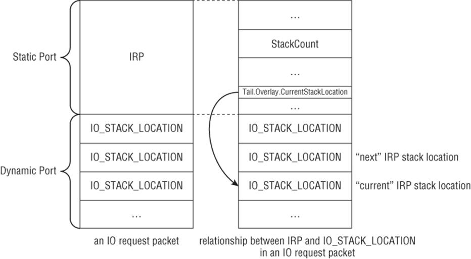
Note that the “next” stack location is the element immediately above the “current” one (not after it). This is important to know because stack location routines such as IoGetCurrentIrpStackLocation, IoSkipCurrentIrpStackLocation, IoGetNextIrpStackLocation, and others are simply returning pointers to these array elements using pointer arithmetic.
Although IRPs are typically generated by the I/O manager in response to requests from users or other devices, they may also be created from scratch and sent to other devices for processing. A driver can allocate an IRP with IoAllocateIrp, associate it with a thread, fill out the IRP major and minor code, set up IO_STACK_LOCATION count/size, fill in parameters, and send it to the destination device for processing with IoCallDriver. Some rootkits use this mechanism to directly send requests to the file system driver in order to bypass system call hooking. You will analyze one such rootkit in the exercise.
Structure of a Driver
A driver is a piece of software that interacts with the kernel and/or controls hardware resources. While there are many different types of drivers, we are primarily concerned with the following types of kernel-mode drivers:
· Legacy software driver—Software that runs in ring 0 and interacts with the kernel through documented and undocumented interfaces. Most rootkits and security drivers are of this type.
· Legacy filter driver—Drivers that attach to an existing driver and modify its input.
· File system minifilter driver—Drivers that interact with the file system to intercept file I/O requests. Most anti-virus software uses this kind of driver to intercept file writes/reads for scanning purposes; on-disk encryption software is typically implemented through this mechanism.
The standard model for Windows drivers is the Windows Driver Model (WDM). WDM defines both a set of interfaces that drivers must implement and rules to follow in order to safely interact with the kernel. It has been defined since Windows 2000 and all drivers you analyze are based on it. Because writing reliable plug-and-play hardware drivers with full power management and handling all the synchronization idiosyncrasies using pure WDM interfaces is exceedingly difficult, Microsoft introduced the Windows Driver Foundation (WDF) framework. WDF is basically a set of libraries built on top of WDM that simplifies driver development by shielding developers from directly interacting with WDM. WDF is divided into two categories: kernel-mode driver framework (KMDF) and user-mode driver framework (UMDF). KMDF is meant for kernel-mode drivers (such as keyboards and USB devices) and UMDF is for user-mode drivers (such as printer drivers). This book deals only with drivers based on the WDM model.
One can think of a driver as a DLL that is loaded into the kernel address space and executes with the same privilege as the kernel. It has a well-defined entry point and may register dispatch routines to service requests from users or other drivers. Note that a driver does not have a main execution thread; it simply contains code that can be called by the kernel under certain circumstances. This is why drivers usually have to register dispatch routines with the I/O manager (see the next section). When analyzing drivers, the first and most important task is to identify these dispatch routines and understand how they interact with the kernel.
Entry Points
All drivers have an entry point called DriverEntry, which is defined as follows:
DriverEntry
NTSTATUS
DriverEntry (
PDRIVER_OBJECT DriverObject,
PUNICODE_STRING RegistryPath
);
DRIVER_OBJECT
typedef struct _DRIVER_OBJECT {
CSHORT Type;
CSHORT Size;
PDEVICE_OBJECT DeviceObject;
ULONG Flags;
PVOID DriverStart;
ULONG DriverSize;
PVOID DriverSection;
PDRIVER_EXTENSION DriverExtension;
UNICODE_STRING DriverName;
PUNICODE_STRING HardwareDatabase;
PFAST_IO_DISPATCH FastIoDispatch;
PDRIVER_INITIALIZE DriverInit;
PDRIVER_STARTIO DriverStartIo;
PDRIVER_UNLOAD DriverUnload;
PDRIVER_DISPATCH MajorFunction[IRP_MJ_MAXIMUM_FUNCTION + 1];
} DRIVER_OBJECT, *PDRIVER_OBJECT;
Note
Technically, the entry point does not have to be named DriverEntry.
When a driver needs to be loaded, its image is mapped into kernel space memory, a driver object is created for it and registered with the object manager, and then the I/O manager calls the entry point. DRIVER_OBJECT is a structure filled out by the I/O manager during the driver loading process; the official documentation indicates that it is a partially opaque structure, but one can view its full definition in the header files. DriverInit is set to the driver's entry point and the I/O manager directly calls this field. The primary responsibility of DriverEntry is to initialize driver-specific settings and register IRP dispatch routines as necessary. These routines are stored in the MajorFunction array. As previously mentioned, Windows has a pre-defined set of IRP major functions to generically describe every I/O request; whenever an I/O request comes in for the driver, the I/O manager calls the appropriate IRP major function handler to process the request. Hence, it is common to see code like the following in DriverEntry:
DriverObject->MajorFunction[IRP_MJ_CREATE] = CreateCloseHandler;
DriverObject->MajorFunction[IRP_MJ_CLOSE] = CreateCloseHandler;
DriverObject->MajorFunction[IRP_MJ_DEVICE_CONTROL] = DeviceControlHandler;
…
Note that the same dispatch routine can be specified for multiple IRP major functions. Sometimes they will be initialized in a loop:
for (i=0; i<IRP_MJ_MAXIMUM; i++) {
DriverObject->MajorFunction[i] = GenericHandler;
}
DriverObject->MajorFunction[IRP_MJ_CREATE] = CreateHandler;
DriverObject->MajorFunction[IRP_MJ_PNP] = PnpHandler;
…
If you do not initialize the MajorFunction table, it will contain the default handler IopInvalidDeviceRequest, which simply returns an error to the requestor.
If a driver supports dynamic unloading, it must also fill out the DriverUnload field; otherwise, the driver will remain in memory forever (until reboot). A DriverUnload routine typically performs driver-specific cleanup tasks. Many rootkits do not register an unload routine.
RegistryPath is the registry path for the driver. It is created as part of the normal driver installation process.
Driver and Device Objects
The previous section states that the I/O manager creates a DRIVER_OBJECT for every driver loaded in the system. A driver can choose to create one or more device objects. Device objects are defined by the partially opaque DEVICE_OBJECT structure:
typedef struct _DEVICE_OBJECT {
CSHORT Type;
USHORT Size;
LONG ReferenceCount;
struct _DRIVER_OBJECT *DriverObject;
struct _DEVICE_OBJECT *NextDevice;
struct _DEVICE_OBJECT *AttachedDevice;
struct _IRP *CurrentIrp;
…
PVOID DeviceExtension;
DEVICE_TYPE DeviceType;
CCHAR StackSize;
…
ULONG ActiveThreadCount;
PSECURITY_DESCRIPTOR SecurityDescriptor;
…
PVOID Reserved;
} DEVICE_OBJECT, *PDEVICE_OBJECT;
DriverObject is the driver object associated with this device object. If the driver created more than one device object, then NextDevice will point to the next device object in the chain. A driver may create multiple device objects to manage different hardware resources it is handling. If no device objects are created, then no one can send requests to the device. Typically, drivers will create device objects in DriverEntry through the IoCreateDevice API.
DeviceExtension is a pointer to device-specific data stored in non-paged pool. Its size is specified as a parameter to IoCreateDevice. Developers typically store context information or important data about the driver and other related devices here. Recovering the device extension structure is probably the second most important task in the analysis of drivers.
A driver can “attach” one of its own device objects to another device object so that it receives I/O requests intended for the target device object. For example, if device A attaches to device B, then all IRP requests sent to B will be routed to A first. This attaching mechanism is used to support filter drivers so that they can modify/inspect requests to other drivers. The AttachedDevice field points to the device to which the current device object is attached. Device attaching is done through the IoAttachDevice API family.
IRP Handling
As mentioned earlier, DriverEntry typically registers dispatch routines to handle various IRP major functions. The prototype for these dispatch routines is as follows:
NTSTATUS
XXX_Dispatch (
PDEVICE_OBJECT *DeviceObject,
PIRP *Irp
);
The first argument is the request's target device object. The second argument is the IRP describing the request.
A dispatch routine typically first determines what IRP major function it received and then determines the request's parameters. It does so by checking the IO_STACK_LOCATION in the IRP. If the dispatch routine successfully completes the request, it calls IoCompleteRequest and returns. If it cannot complete the request, then it has three options: return an error, pass the IRP to another driver, or pend the IRP. For example, a filter driver may choose to process only IRP_MJ_READ requests itself and pass all other requests to the attached device. A driver can pass IRPs to another driver through theIoCallDriver API.
Because IRP parameters for each request are stored in their own IO_STACK_LOCATION, a driver must ensure that it is accessing the right location. This is done through the IoGetCurrentIrpStackLocation API. If the driver wants to pass the same IRP to another driver, it has to either copy the current parameters to the next IO_STACK_LOCATION (IoCopyCurrentIrpStackLocationToNext) or pass the parameter to the next driver (IoSkipCurrentStackLocation).
A Common Mechanism for User-Kernel Communication
Many mechanisms are used to facilitate user-kernel communication. For example, a driver can communicate with user-mode code through a shared memory region double-mapped in user and kernel space. Another method is for the driver to create an event that a user-mode thread can wait on; the event state can be used as a trigger for further action. Yet another (although hackish) method is through interrupt handling. A driver can manually set up a custom interrupt handler in the IDT and user-mode code can trigger it with the INT instruction; you will probably never see this technique used in a commercial driver.
While the precise communication mechanism depends on the developer's ultimate goal, a generic documented interface is typically used for user-kernel data exchange. This mechanism is supported by the IRP_MJ_DEVICE_CONTROL operation and commonly referred to as device I/O control or simply IOCTL. It works as follows:
1. The driver defines one or more IOCTL codes for each operation it supports.
2. For each supported operation, the driver specifies how it should access the user input and return data to the user. There are three access methods: buffered I/O, direct I/O, and neither. These methods are covered in the next section.
3. Inside the IRP_MJ_DEVICE_CONTROL handler, the driver retrieves the IOCTL code from its IO_STACK_LOCATION and processes the data based on the input method.
User-mode code can request these IOCTL operations through the DeviceIoControl API.
Buffering Methods
A driver can access a user-mode buffer using one of the following three methods:
· Buffered I/O—This is referred to as METHOD_BUFFERED in the kernel. When using this method, the kernel validates the user buffer to be in accessible user-mode memory, allocates a block of memory in non-paged pool, and copies the user buffer to it. The driver accesses this kernel-mode buffer through the AssociatedIrp.SystemBuffer field in the IRP structure. While processing the request, the driver may modify the system buffer (perhaps it needs to return some data back to the user); after completing the request, the kernel copies the system buffer's content back to the user-mode buffer and automatically frees the system buffer.
· Direct IO—This is referred to as METHOD_IN_DIRECT or METHOD_OUT_DIRECT in the kernel. The former is used for passing data to the driver; the latter is used for getting data from the driver. This method is similar to buffered I/O except that the driver gets an MDL describing the user buffer. The I/O manager creates the MDL and locks it in memory before passing it to the driver. Drivers can access this MDL through the MdlAddress field of the IRP structure.
· Neither—This is referred to as METHOD_NEITHER in the kernel. When using this method, the I/O manager does not perform any kind of validation on the user data; it passes the raw data to the driver. Drivers can access the data through the Parameters.DeviceIoControl.Type3InputBuffer field in its IO_STACK_LOCATION. While this method may seem the fastest of the three (as there is no validation or mapping of additional buffers), it is certainly the most insecure one. It leaves all the validation to the developer. Without proper validation, a driver using this method may expose itself to security vulnerabilities such as kernel memory corruption or leakage/disclosure.
There is no written rule for determining which method to use in drivers because it depends on the driver's specific requirements. However, in practice, most software drivers use buffered I/O because it provides a good balance between simplicity and security. Direct I/O is common in hardware drivers because it can be used to pass large data chunks without buffering overhead.
I/O Control Code
An IOCTL code is a 32-bit integer that encodes the device type, operation-specific code, buffering method, and security access. Drivers usually define IOCTL codes through the CTL_CODE macro:
#define CTL_CODE( DeviceType, Function, Method, Access ) ( \
((DeviceType) ![]() 16) | ((Access)
16) | ((Access) ![]() 14) | ((Function)
14) | ((Function) ![]() 2) | (Method) \
2) | (Method) \
)
DeviceType is usually one of the FILE_DEVICE_* constants, but for third-party drivers it can use anything above 0x8000. (This is only the recommended value and there is nothing enforcing it.) Access specifies generic read/write operations allowed by the IOCTL; it can be a combination ofFILE_ANY_ACCESS, FILE_READ_ACCESS, and FILE_WRITE_ACCESS. Function is the driver-specific IOCTL code; it can be anything above 0x800. Method specifies one of the buffering methods.
A typical way to define an IOCTL code is as follows:
#define FILE_DEVICE_GENIOCTL 0xa000 // our device type
#define GENIOCTL_PROCESS 0x800 // our special IOCTL code
#define IOCTL_PROCESS CTL_CODE(FILE_DEVICE_GENIOCTL, \
GENIOCTL_PROCESS, \
METHOD_BUFFERED, FILE_READ_DATA)
This defines an IOCTL called IOCTL_PROCESS for a custom driver using METHOD_BUFFERED.
When analyzing a driver, it is important to decompose the IOCTL down to its device type, code, access, and buffering method. This can be achieved with a couple of simple documented macros:
#define DEVICE_TYPE_FROM_CTL_CODE(ctrlCode) \
(((ULONG)(ctrlCode & 0xffff0000)) ![]() 16)
16)
#define METHOD_FROM_CTL_CODE(ctrlCode) ((ULONG)(ctrlCode & 3)
Miscellaneous System Mechanisms
This section discusses constructs that—while not essential to understanding kernel drivers—are frequently observed in real-life drivers.
System Control Registers
In order to achieve their goals, many rootkit developers resort to hooking functions in the kernel. However, all kernel code is mapped as read-only, so patching it will result in a bugcheck. On x86/x64, this protection mechanism is actually enforced at the hardware level through a special control register: CR0. CR0 determines several important processor settings, such as whether it is in protected mode and whether paging is enabled; it also determines whether the CPU can write to read-only pages (WP bit). CR0 is only accessible by code running in ring 0. By default, Windows turns on the WPbit, which prohibits writes to pages marked read-only.
Note
On x64 and ARM, there is a Windows feature called Kernel Patch Protection, also known as PatchGuard, that tries to detect hooks and modifications to various security-critical data structures and bugchecks the machine. Hence, it is not common to see hooks on these platforms in shipping/production drivers. Nevertheless, hooking is still prevalent because there are many x86 machines out there, so you will frequently run into them.
There are several ways to bypass this restriction and the easiest one is to toggle the WP bit. Hence, you will frequently see this code pattern in rootkits. For example, Sample G:
01: .text:0001062F push eax
02: .text:00010630 mov eax, cr0
03: .text:00010633 mov [esp+8+var_4], eax
04: .text:00010637 and eax, 0FFFEFFFFh
05: .text:0001063C mov cr0, eax
06: .text:0001063F pop eax
Lines 2–3 copy CR0 to EAX and save it to a local variable. Lines 4–5 turn off the bit 16 in EAX and write it back to CR0. Bit 16 in CR0 is the WP bit.
There are at least two other solutions that do not directly modify CR0. They involve MDLs and knowledge of the platform MMU. You will be required to do this as one of the exercises.
KeServiceDescriptorTable
As previously stated, many rootkits resort to hooking system calls. However, as you learned, system calls are identified by a number that is used as an index into a syscall table. Furthermore, the system call table (KiServiceTable) is not exported, so there is no easy way to access it from a driver. How do rootkit authors get around this?
The kernel exports the KeServiceDescriptorTable symbol, which contains a KSERVICE_TABLE_DESCRIPTOR structure with the system call information. (Recall that on x64, this symbol is not exported.) This is how most rootkits access the system call table. The next step is to identify where the target system call is located. Recall that system calls are identified by a number, not by name. Rootkit authors have several ways to find the right system call. One way is to hardcode the syscall index. Another method is to disassemble the system call stub and get the index from there. Both of these methods have a trade-off: They are simple to implement, but they rely on code or data patterns that may change from service pack to service pack; they may be reliable on some platforms, but will certainly lead to system instability on others. Despite the unreliability, these two methods are frequently used by rootkits in the wild. For example, Sample G has the following code:
01: .text:000117D4 sub_117D4 proc near
02: .text:000117D4 push ebp
03: .text:000117D5 mov ebp, esp
04: .text:000117D7 push ecx
05: .text:000117D8 mov ecx, ds:KeServiceDescriptorTable
06: .text:000117DE mov ecx, [ecx]
07: .text:000117E0 push esi
08: .text:000117E1 mov esi, ds:ZwQuerySystemInformation
09: …
10: .text:00011808 call DisableWP
11: .text:0001180D mov ecx, ds:KeServiceDescriptorTable
12: .text:00011813 mov eax, [esi+1]
13: .text:00011816 mov ecx, [ecx]
14: .text:00011818 mov dword ptr [ecx+eax*4], offset sub_1123E
15: …
16: .text:00011836 sub_117D4 endp
Lines 5–10 save the address of KiServiceTable in ECX, save the address of ZwQuerySystemInformation in ESI, and disable the WP bit. Line 12 retrieves the second byte from ZwQuerySystemInformation; it does this because it assumes that the first instruction in the function moves the syscall number to a register and hence the 32-bit value after the opcode contains the actual syscall number (see the following sidebar). Lines 13–14 overwrite that syscall entry in the service table with a new function: sub_1123e. All calls to ZwQuerySystemInformation will now be redirected to sub_1123e.
Note
We mentioned earlier that line 12 retrieves the second byte from ZwQuerySystemInformation. On 32-bit Windows 7, the first instruction in ZwQuerySystemInformation is b805010000 mov eax and 105h. b8 is the MOV opcode, while 05010000 (0x105) encodes the immediate, which in this case is the syscall number.
Sections
A section is an object used to describe memory backed by some form of storage. The section can be backed by a normal file or a page file. A file-backed section is one for which the memory content is that of a file on disk; if there are modifications to the section, they will be made directly to disk. A page-file-backed section is one whose content is backed by the page file; modifications to such a section will be discarded after it is closed. A driver can create a section with the ZwCreateSection API and then map a view of it into another process with ZwMapViewOfSection. Each view is basically a virtual address range that can be used to access the memory represented by the associated section object. Hence, there can be multiple views for a section.
Walk-Throughs
Now that you have a strong grasp of Windows kernel and driver concepts, it is time to apply that knowledge by analyzing some real-life rootkits. This section serves two purposes: to explain the thinking process of kernel-mode reverse engineering and to demonstrate the application of driver development techniques to understanding rootkits.
Rootkits come in many different forms. Some hook system calls, some hide files by filtering I/O responses, some intercept network communication, some log keystrokes, and so on. However, like all drivers, they share the same generic structure; for example, they all have a DriverEntry function with optional IRP dispatch handlers that interface with the kernel through documented and undocumented interfaces. With this knowledge, you can dissect core components of a driver and systematically analyze them. The general analysis process is as follows:
1. Identify DriverEntry and determine the IRP dispatch handlers, if any.
2. Determine whether the driver attaches to another device to filter/intercept its I/O requests. If so, what is the target device?
3. If the driver creates a device object, determine the name and device extension size.
4. Recover the device extension structure by observing how its field members are used.
5. If the driver supports IOCTL, identify all the IOCTL codes and their corresponding functionality. Determine what buffering method they use.
6. Identify DPCs, work items, APCs, timers, completion routines, callbacks, and system threads.
7. Try to understand how all the pieces fit together.
An x86 Rootkit
The walk-through begins with Sample A.
Its DriverEntry starts at 0x105F0 and ends at 0x106AD. It first initializes a UNICODE_STRING structure with the strings \Device\fsodhfn2m and \DosDevices\fsodhfn2m. In kernel mode, most strings are described using the UNICODE_STRING structure:
typedef struct _UNICODE_STRING {
USHORT Length;
USHORT MaximumLength;
PWSTR Buffer;
} UNICODE_STRING, *PUNICODE_STRING;
It is initialized through the RtlInitUnicodeString API. The “Device” string is a device name in the object manager; the “DosDevices” string is used as a symbolic link to the actual device name. The Windows object manager maintains and organizes objects in a filesystem-like structure with the root at “\”. There are well-defined directories such as \Devices, \BaseNamedObjects, \KernelObjects, and so on. \DosDevices is an alias for the \?? directory; it is there because when user-mode applications specify the path to an object they want to access, the \??\ is prepended to it; \?? contains symbolic links pointing to the real object. For example, when a user wants to access “c:\test.txt” through the CreateFile API, the actual path sent to the kernel is “\??\c:\test.txt”; because “c:” is a symbolic link to \Device\HarddiskVolume2 (it may vary on your system), the whole path will eventually resolve to \Device\HarddiskVolume2\test.txt. The symbolic link is necessary because user-mode APIs usually access devices through the \?? directory; if there were no symbolic links there, the device may not be accessible to user-mode apps.
After initializing the two strings, it proceeds to create the actual device object. IoCreateDevice is defined as follows:
NTSTATUS
IoCreateDevice(
IN PDRIVER_OBJECT DriverObject,
IN ULONG DeviceExtensionSize,
IN PUNICODE_STRING DeviceName OPTIONAL,
IN DEVICE_TYPE DeviceType,
IN ULONG DeviceCharacteristics,
IN BOOLEAN Exclusive,
OUT PDEVICE_OBJECT *DeviceObject
);
DriverObject is the caller's DRIVER_OBJECT; it is the driver object that the new device object is associated with. DeviceExtensionSize is how many bytes of non-paged pool memory should be allocated for the driver-specific structure. Because it is a user-defined structure, it is very important to recover its fields. DeviceName is the native device name. DeviceType is one of the pre-defined FILE_DEVICE_* types; if the device does not fall into a generic category, FILE_DEVICE_UNKNOWN is used instead. DeviceCharacteristics refers to the device characteristic; most of the time you will seeFILE_DEVICE_SECURE_OPEN. Exclusive determines whether there can be more than one handle to the device. DeviceObject receives the actual device object.
From the disassembly, you can decompile the first basic block and its exiting condition as follows:
01: UNICODE_STRING devname;
02: UNICODE_STRING symname;
03:
04: NTSTATUS DriverEntry(PDRIVER_OBJECT DriverObject, \
PUNICODE_STRING regpath)
05: {
06: NTSTATUS status;
07: PDEVICE_OBJECT devobj;
08:
09: RtlInitUnicodeString(&devname, L"\\Device\\fsodhfn2m");
10: RtlInitUnicodeString(&symname, L"\\DosDevices\\fsodhfn2m");
11: status = IoCreateDevice(
12: DriverObject,
13: 0,
14: &devname,
15: FILE_DEVICE_UNKNOWN,
16: FILE_DEVICE_SECURE_OPEN,
17: FALSE,
18: &devobj);
19: if (!NT_SUCCESS(status)) {
20: return status; // loc_106A3
21: }
22: }
NT_SUCCESS() is a common macro that checks if status is greater than or equal to 0. After successfully creating the object, it proceeds to the following:
01: .text:00010643 mov ecx, [ebp+DriverObject]
02: .text:00010646 mov dword ptr [ecx+38h], offset sub_10300
03: .text:0001064D mov edx, [ebp+DriverObject]
04: .text:00010650 mov dword ptr [edx+40h], offset sub_10300
05: .text:00010657 mov eax, [ebp+DriverObject]
06: .text:0001065A mov dword ptr [eax+70h], offset sub_10300
07: .text:00010661 mov ecx, [ebp+DriverObject]
08: .text:00010664 mov dword ptr [ecx+34h], offset sub_10580
09: .text:0001066B push offset SymbolicLinkName ; SymbolicLinkName
10: .text:00010670 call ds:IoDeleteSymbolicLink
11: .text:00010676 push offset DestinationString ; DeviceName
12: .text:0001067B push offset SymbolicLinkName ; SymbolicLinkName
13: .text:00010680 call ds:IoCreateSymbolicLink
14: .text:00010686 mov [ebp+var_4], eax
15: .text:00010689 cmp [ebp+var_4], 0
16: .text:0001068D jge short loc_106A1
Lines 1–8 set some DRIVER_OBJECT fields to two function pointers. What is at offset 0x38, 0x40, 0x70, and 0x34?
0: kd> dt _DRIVER_OBJECT
nt!_DRIVER_OBJECT
+0x000 Type : Int2B
+0x002 Size : Int2B
+0x004 DeviceObject : Ptr32 _DEVICE_OBJECT
…
+0x034 DriverUnload : Ptr32 void
+0x038 MajorFunction : [28] Ptr32 long
Offset 0x34 is the DriverUnload routine; now, you know that the driver supports dynamic unloading and sub_10580 is the unload routine. Offset 0x38 is the beginning of the MajorFunction array; recall that this is an array of IRP dispatch handlers. Because there is a maximum of 28 generic IRP major functions, the MajorFunction array has 28 members. The first index is 0, which corresponds to IRP_MJ_CREATE; hence, you know that sub_10300 is the handler for that IRP. Offset 0x40 is the third element in the MajorFunction array (index 2); this corresponds to IRP_MJ_CLOSE, and sub_10300 is reused as the handler. Offset 0x70 is the 16th element in the array (index 0xe), which corresponds to IRP_MJ_DEVICE_CONTROL, and sub_10300 is the handler. At this point, you know that sub_10300 is the handler for the read, close, and device control IRP.
Lines 10–13 delete any existing symbolic link and create a new one to point to the device object previously created.
You can now continue decompiling this block in DriverEntry as follows:
01: DriverObject->MajorFunction[IRP_MJ_READ] = sub_10300;
02: DriverObject->MajorFunction[IRP_MJ_CLOSE] = sub_10300;
03: DriverObject->MajorFunction[IRP_MJ_DEVICE_CONTROL] = sub_10300;
04: DriverObject->DriverUnload = sub_10580;
05:
06: IoDeleteSymbolicLink(&symname);
07: status = IoCreateSymbolicLink(&symname, &devname);
08: if (!NT_SUCCESS(status)) {
09: … // block .text:0001068F
10: return status;
11: }
12: return status;
To make life easier, you can rename sub_10300 as IRP_ReadCloseDeviceIo and sub_10580 as DRV_Unload.
The next block at 0x1068F deletes the previously created device object if the symbolic link creation fails. Note that it is getting the device object from the driver object instead of using the pointer passed to IoCreateDevice. You can decompile this block as follows:
01: IoDeleteDevice(DriverObject->DeviceObject);
That completes decompilation of this rootkit's DriverEntry. To summarize what has been learned so far:
· The driver creates a device object named \Device\fsodhfn2m.
· It supports dynamic unloading and the unload routine is sub_10580 (renamed to DRV_Unload).
· It supports IRP_MJ_READ, IRP_MJ_WRITE, and IRP_MJ_DEVICE_CONTROL operations, and sub_10300 is the handler (renamed to IRP_ReadCloseDeviceIo).
· It creates a symbolic link to the device object. If that fails, the driver returns an error.
The next step is to understand what the DriverUnload routine does. The WDK defines the prototype for the driver unload routine as follows:
VOID
Unload(
PDRIVER_OBJECT *DriverObject
);
After some minor massaging, our unload routine looks like this:
01: .text:00010580 ; void __stdcall DRV_Unload(PDRIVER_OBJECT drvobj)
02: .text:00010580 DRV_Unload proc near
03: .text:00010580
04: .text:00010580 drvobj= dword ptr 8
05: .text:00010580
06: .text:00010580 push ebp
07: .text:00010581 mov ebp, esp
08: .text:00010583 push offset SymbolicLinkName ; SymbolicLinkName
09: .text:00010588 call ds:IoDeleteSymbolicLink
10: .text:0001058E mov eax, [ebp+drvobj]
11: .text:00010591 mov ecx, [eax+DRIVER_OBJECT.DeviceObject]
12: .text:00010594 push ecx ; DeviceObject
13: .text:00010595 call ds:IoDeleteDevice
14: .text:0001059B pop ebp
15: .text:0001059C retn 4
16: .text:0001059C DRV_Unload endp
The preceding can be decompiled to the following:
01: VOID DRV_Unload(PDRIVER_OBJECT drvobj)
02: {
03: IoDeleteSymbolicLink(&symname);
04: IoDeleteDevice(drvobj->DeviceObject);
05: }
As previously stated, an important key to understanding a driver's functionality is through its IRP dispatch handlers. Analyzing _IRP_ReadCloseDeviceIo, we start at the beginning:
01: .text:00010300 ; NTSTATUS __stdcall IRP_ReadCloseDeviceIO(
PDEVICE_OBJECT devobj, PIRP Irp)
02: .text:00010300 IRP_ReadCloseDeviceIO proc near
03: .text:00010300 var_14= dword ptr -14h
04: .text:00010300 var_10= dword ptr -10h
05: .text:00010300 var_C= dword ptr -0Ch
06: .text:00010300 var_8= dword ptr -8
07: .text:00010300 var_4= dword ptr -4
08: .text:00010300 devobj= dword ptr 8
09: .text:00010300 Irp= dword ptr 0Ch
10: .text:00010300
11: .text:00010300 push ebp
12: .text:00010301 mov ebp, esp
13: .text:00010303 sub esp, 14h
14: .text:00010306 mov [ebp+var_4], 0
15: .text:0001030D mov eax, [ebp+Irp]
16: .text:00010310 mov ecx, [ebp+var_4]
17: .text:00010313 mov [eax+18h], ecx
18: .text:00010316 mov edx, [ebp+Irp]
19: .text:00010319 mov dword ptr [edx+1Ch], 0
20: .text:00010320 mov eax, [ebp+Irp]
21: .text:00010323 mov ecx, [eax+60h]
22: .text:00010326 mov [ebp+var_10], ecx
23: .text:00010329 mov edx, [ebp+var_10]
24: .text:0001032C movzx eax, byte ptr [edx]
25: .text:0001032F cmp eax, 0Eh
26: .text:00010332 jnz short loc_1037D
We already know its prototype because it is the same for all IRP handlers. When analyzing IRP handlers, you need to be cognizant of a few facts:
· An IRP is a dynamic structure with an array of IO_STACK_LOCATION after its header.
· Most of the IRP parameters are in the IO_STACK_LOCATION (including its IRP major/minor number).
· A driver accesses its IO_STACK_LOCATION using the IoGetCurrentIrpStacLocation routine. Because this routine is forced-inline, you must recognize it through its inlined patterns. It is a common coding pattern to retrieve the IO_STACK_LOCATION in the beginning of an IRP handler.
Lines 15–17 read the IRP structure and write a 0 to a field at offset 0x18. Looking at the IRP structure you see the following:
0: kd> dt nt!_IRP
+0x000 Type : Int2B
+0x002 Size : Uint2B
…
+0x00c AssociatedIrp : <unnamed-tag>
…
+0x018 IoStatus : _IO_STATUS_BLOCK
+0x000 Status : Int4B
+0x000 Pointer : Ptr32 Void
+0x004 Information : Uint4B
…
+0x020 RequestorMode : Char
…
+0x040 Tail : <unnamed-tag>
An IO_STATUS_BLOCK structure stores status information about an IRP:
typedef struct _IO_STATUS_BLOCK {
union {
NTSTATUS Status;
PVOID Pointer;
};
ULONG_PTR Information;
} IO_STATUS_BLOCK, *PIO_STATUS_BLOCK;
An IRP handler typically sets the Status field to indicate whether the IRP was successful or requires further processing. Information stores request-specific information for the IRP; a driver may use it to store a pointer to a buffer or set the completion status. Pointer is reserved.
Hence, you know that line 17 sets the IRP->IoStatus.Status field to 0 and that the local variable var_4 is of type NTSTATUS. Lines 18–19 access the IRP structure and write a 0 at offset 0x1c, which is the Information field in IoStatus. This is simply setting IRP->IoStatus.Information to 0. Lines 20–22 access offset 0x60 in the IRP structure and save its address in a local variable. The IRP structure is filled with unions in the Tail field (starting at offset 0x40), so it can be somewhat confusing to determine which union field member is accessed. Let's dump some of the unions:
0: kd> dt nt_IRP Tail.Overlay.
+0x040 Tail :
+0x000 Overlay :
+0x000 DeviceQueueEntry : _KDEVICE_QUEUE_ENTRY
+0x000 DriverContext : [4] Ptr32 Void
+0x010 Thread : Ptr32 _ETHREAD
+0x014 AuxiliaryBuffer : Ptr32 Char
+0x018 ListEntry : _LIST_ENTRY
+0x020 CurrentStackLocation : Ptr32 _IO_STACK_LOCATION
+0x020 PacketType : Uint4B
+0x024 OriginalFileObject : Ptr32 _FILE_OBJECT
This indicates that offset 0x60 could be either a pointer to an IO_STACK_LOCATION or an unsigned integer indicating the packet type. We can make an educated guess that it is the CurrentStackLocation field because of the code context (occurring at the beginning of an IRP handler). Furthermore, we know that the inlined routine IoGetCurrentIrpStackLocation is defined as follows:
FORCEINLINE
PIO_STACK_LOCATION
IoGetCurrentIrpStackLocation(PIRP Irp)
{
return Irp->Tail.Overlay.CurrentStackLocation;
}
Therefore, lines 20–22 are saving the current IO_STACK_LOCATION to a local variable. The local variable _var_10 is of the type PIO_STACK_LOCATION.
Note
Many of these functions are declared as FORCEINLINE and thus will never appear as call destinations—i.e., you will never see see the symbol IoGetCurrentIrpStackLocation in the assembly code. We recommend that you write a simple driver using these forced-inline routines so that you can get used to the code pattern.
Lines 23–25 access the first byte at offset 0 in the IO_STACK_LOCATION using the MOVZX instruction. This indicates that field is of type unsigned char. From the IRP section, we know that this is the MajorFunction field. Line 5 checks whether the MajorFunction number is 0xe, i.e.,IRP_MJ_DEVICE_CONTROL.
You can now decompile the first block of IRP_ReadCloseIo as follows:
NTSTATUS IRP_ReadCloseIo(PDEVICE_OBJECT devobj, PIRP Irp)
{
NTSTATUS status = STATUS_SUCCESS;
PIO_STACK_LOCATION isl;
Irp->IoStatus.Status = status;
Irp->IoStatus.Information = 0;
isl = IoGetCurrentIrpStackLocation(Irp);
if (isl->MajorFunction != IRP_MJ_DEVICE_CONTROL) {
… // loc_1037D
}
… // .text:00010334
}
Next, we analyze block 0x10334, which executes if major code is IRP_MJ_DEVICE_CONTROL:
01: .text:00010334 mov ecx, [ebp+var_10]
02: .text:00010337 mov edx, [ecx+0Ch]
03: .text:0001033A mov [ebp+var_C], edx
04: .text:0001033D mov eax, [ebp+Irp]
05: .text:00010340 mov ecx, [eax+0Ch]
06: .text:00010343 mov [ebp+var_8], ecx
07: .text:00010346 mov edx, [ebp+Irp]
08: .text:00010349 mov dword ptr [edx+1Ch], 644h
09: .text:00010350 mov eax, [ebp+var_C]
10: .text:00010353 mov [ebp+var_14], eax
11: .text:00010356 cmp [ebp+var_14], 22C004h
12: .text:0001035D jz short loc_10361
In the previous paragraph, we deduced that var_10 is of type PIO_STACK_LOCATION. Lines 1–2 access offset 0xC of the IO_STACK_LOCATION. Again, recall that an IO_STACK_LOCATION contains the I/O request parameters, which are all stored in unions. How do you determine which union to use? We know that it will use the DeviceIoControl field because we are processing an IRP_MJ_DEVICE_CONTROL request. Also, the IoControlField is at offset 0xC from the base of IO_STACK_LOCATION:
1: kd> dt nt!_IO_STACK_LOCATION Parameters.
+0x004 Parameters :
+0x000 Create : <unnamed-tag>
+0x000 CreatePipe : <unnamed-tag>
+0x000 CreateMailslot : <unnamed-tag>
+0x000 Read : <unnamed-tag>
+0x000 Write : <unnamed-tag>
+0x000 QueryDirectory : <unnamed-tag>
…
+0x000 DeviceIoControl : <unnamed-tag>
…
1: kd> dt nt!_IO_STACK_LOCATION Parameters.DeviceIoControl.
+0x004 Parameters :
+0x000 DeviceIoControl :
+0x000 OutputBufferLength : Uint4B
+0x004 InputBufferLength : Uint4B
+0x008 IoControlCode : Uint4B
+0x00c Type3InputBuffer : Ptr32 Void
Therefore, lines 1–3 retrieve the IoControlCode field and save it in var_C, which we now know is of type ULONG.
Lines 4–6 access offset 0xC in an IRP and save the pointer to a local variable var_8. From the previous section, we know that at offset 0xC is the AssociatedIrp union:
1: kd> dt nt!_IRP AssociatedIrp.
+0x00c AssociatedIrp :
+0x000 MasterIrp : Ptr32 _IRP
+0x000 IrpCount : Int4B
+0x000 SystemBuffer : Ptr32 Void
Which of the three fields should you use? Given the current information, you cannot tell. The context required to determine the proper field is in lines 9–12, which retrieve the saved IOCTL code (var_C) and compare it against 0x22c004. You know that an IOCTL code encodes device type, function code, access, and buffering method. Hence, after decoding 0x22c004, you know the following:
· Device type is FILE_DEVICE_UNKNOWN (0x22).
· The IOCTL code is 0x1.
· Access is (FILE_READ_DATA | FILE_WRITE_DATA).
· Buffering method is METHOD_BUFFERED.
Recall that we are in an IOCTL handler and that drivers must specify a buffering method when defining the IOCTL code. For buffered I/O, the SystemBuffer field points to a non-paged pool buffer storing the user input. We can now say that lines 4–6 access the SystemBuffer field.
Lines 7–8 write 0x644 to offset 0x1c inside an IRP, which is the IRP->IoStatus.Information field. It is unclear why the author chose this value.
Given this information, you know that the control code must have been constructed this way:
#define IOCTL_1 CTL_CODE(FILE_DEVICE_UNKNOWN, 1, METHOD_BUFFERED, \
FILE_READ_DATA | FILE_WRITE_DATA)
Because we have not fully analyzed or understood the IOCTL operation, we gave it the generic IOCTL_1 name. This block can now be decompiled as follows:
PVOID userinput = Irp->AssociatedIrp.SystemBuffer;
Irp->IoStatus.Information = (ULONG_PTR) 0x644;
if (isl->Parameters.DeviceIoControl.IoControlCode == IOCTL_1)
{
… // loc_10361
}
… // 0001035F
To understand what the IOCTL does, we need to analyze loc_10361 and the function sub_103B0. However, before doing that, let's finish the nearby blocks first (as they are simpler):
// remember var_4 is status local variable (type NTSTATUS)
01: .text:0001035F jmp short loc_1036C
02: .text:00010361 loc_10361:
03: .text:00010361 mov ecx, [ebp+var_8] ;
04: .text:00010364 push ecx
05: .text:00010365 call IOCTL_1_handler
06: .text:0001036A jmp short loc_1037D
07: .text:0001036C loc_1036C:
08: .text:0001036C mov [ebp+var_4], 0C0000010h
09: .text:00010373 mov edx, [ebp+Irp]
10: .text:00010376 mov dword ptr [edx+1Ch], 0
11: .text:0001037D loc_1037D:
12: .text:0001037D cmp [ebp+var_4], 103h
13: .text:00010384 jz short loc_1039A
14: .text:00010386 xor dl, dl ; PriorityBoost
15: .text:00010388 mov ecx, [ebp+Irp] ; Irp
16: .text:0001038B call ds:IofCompleteRequest
17: .text:00010391 mov eax, [ebp+Irp]
18: .text:00010394 mov ecx, [ebp+var_4]
19: .text:00010397 mov [eax+18h], ecx
20: .text:0001039A loc_1039A:
21: .text:0001039A mov eax, [ebp+var_4]
22: .text:0001039D mov esp, ebp
23: .text:0001039F pop ebp
24: .text:000103A0 retn 8
25: .text:000103A0 IRP_ReadCloseDeviceIO endp
You enter 0x1035F if the IOCTL code does not match up. It immediately jumps to line 7, which sets the local status variable to 0xC0000010, which is STATUS_INVALID_OPERATION; and Irp->IoStatus.Information to 0. Next, in line 11, it checks whether the local status is 0x103 (STATUS_PENDING); this block is actually redundant because the status variable in this function can only have two values (STATUS_SUCCESS or STATUS_INVALID_OPERATION). When an IRP is marked with STATUS_PENDING, it means that the operation is incomplete and is awaiting completion from another driver. This occurs often in drivers so it is wise to remember the magic constant 0x103. If the status is STATUS_PENDING, the handler immediately returns with that status (line 13 and 20). Otherwise, it calls IoCompleteRequest to mark the IRP completed and saves the status in IRP->IoStatus.Status (line 19) and returns it. This is actually a bug because a driver should set the IoStatusBlock field before completing the request; once an IRP is completed, it should not be touched again. These blocks can be decompiled as follows:
status = STATUS_INVALID_OPERATION;
Irp->IoStatus.Information = 0;
if (status == STATUS_PENDING) {
return status;
}
IoCompleteRequest(Irp, IO_NO_INCREMENT);
Irp->IoStatus.Status = status;
return status;
Returning to the IOCTL_1_handler routine, note that it calls only two other functions: sub_10460 and sub_10550. sub_10550 is a small leaf routine so we will analyze that first:
01: .text:00010550 ; void __stdcall sub_10550(PMDL Mdl, PVOID BaseAddress)
02: .text:00010550 sub_10550 proc near
03: .text:00010550 push ebp
04: .text:00010551 mov ebp, esp
05: .text:00010553 mov eax, [ebp+Mdl]
06: .text:00010556 push eax ; MemoryDescriptorList
07: .text:00010557 mov ecx, [ebp+BaseAddress]
08: .text:0001055A push ecx ; BaseAddress
09: .text:0001055B call ds:MmUnmapLockedPages
10: .text:00010561 mov edx, [ebp+Mdl]
11: .text:00010564 push edx ; MemoryDescriptorList
12: .text:00010565 call ds:MmUnlockPages
13: .text:0001056B mov eax, [ebp+Mdl]
14: .text:0001056E push eax ; Mdl
15: .text:0001056F call ds:IoFreeMdl
16: .text:00010575 pop ebp
17: .text:00010576 retn 8
18: .text:00010576 sub_10550 endp
This function unmaps, unlocks, and frees an MDL. It is unclear what the MDLs describe because we have not analyzed the other routines. This function can be decompiled as follows:
void UnmapMdl(PMDL mdl, PVOID baseaddr)
{
MmUnmapLockedPages(baseaddr, mdl);
MmUnlockPages(mdl);
IoFreeMdl(mdl);
}
sub_10460 is another leaf routine involving MDLs; its main functionality is to create, lock, and map an MDL for a given buffer and length. Its prototype is as follows:
PVOID MapMdl(PMDL *mdl, PVOID VirtualAddress, ULONG Length);
By default, the disassembler was not able to infer the first parameter's type. You can tell that it is a PMDL * because of instruction at 0x1049D. The assembly listing is shown here but without line-by-line commentary, as it is very simple:
01: .text:00010460 ; PVOID __stdcall MapMdl(PMDL *mdl,
PVOID VirtualAddress, ULONG Length)
02: .text:00010460 MapMdl proc near
03: .text:00010460 push ebp
04: .text:00010461 mov ebp, esp
05: .text:00010463 push 0FFFFFFFFh
06: .text:00010465 push offset unk_10748
07: .text:0001046A push offset _except_handler3
08: .text:0001046F mov eax, large fs:0
09: .text:00010475 push eax
10: .text:00010476 mov large fs:0, esp
11: .text:0001047D add esp, 0FFFFFFF0h
12: .text:00010480 push ebx
13: .text:00010481 push esi
14: .text:00010482 push edi
15: .text:00010483 mov [ebp+var_18], esp
16: .text:00010486 push 0 ; Irp
17: .text:00010488 push 0 ; ChargeQuota
18: .text:0001048A push 0 ; SecondaryBuffer
19: .text:0001048C mov eax, [ebp+Length]
20: .text:0001048F push eax ; Length
21: .text:00010490 mov ecx, [ebp+VirtualAddress]
22: .text:00010493 push ecx ; VirtualAddress
23: .text:00010494 call ds:IoAllocateMdl
24: .text:0001049A mov edx, [ebp+mdl]
25: .text:0001049D mov [edx], eax
26: .text:0001049F mov eax, [ebp+mdl]
27: .text:000104A2 cmp dword ptr [eax], 0
28: .text:000104A5 jnz short loc_104AE
29: .text:000104A7 xor eax, eax
30: .text:000104A9 jmp loc_10534
31: .text:000104AE loc_104AE:
32: .text:000104AE mov [ebp+var_4], 0
33: .text:000104B5 push 1 ; Operation
34: .text:000104B7 push 0 ; AccessMode
35: .text:000104B9 mov ecx, [ebp+mdl]
36: .text:000104BC mov edx, [ecx]
37: .text:000104BE push edx ; MemoryDescriptorList
38: .text:000104BF call ds:MmProbeAndLockPages
39: .text:000104C5 mov [ebp+var_4], 0FFFFFFFFh
40: .text:000104CC jmp short loc_104F6
41: .text:000104CE loc_104CE:
42: .text:000104CE mov eax, 1
43: .text:000104D3 retn
44: .text:000104D4 loc_104D4:
45: .text:000104D4 mov esp, [ebp+var_18]
46: .text:000104D7 mov eax, [ebp+mdl]
47: .text:000104DA mov ecx, [eax]
48: .text:000104DC push ecx ; Mdl
49: .text:000104DD call ds:IoFreeMdl
50: .text:000104E3 mov [ebp+var_20], 0
51: .text:000104EA mov [ebp+var_4], 0FFFFFFFFh
52: .text:000104F1 mov eax, [ebp+var_20]
53: .text:000104F4 jmp short loc_10534
54: .text:000104F6 loc_104F6:
55: .text:000104F6 push 10h ; Priority
56: .text:000104F8 push 0 ; BugCheckOnFailure
57: .text:000104FA push 0 ; BaseAddress
58: .text:000104FC push 0 ; CacheType
59: .text:000104FE push 0 ; AccessMode
60: .text:00010500 mov edx, [ebp+mdl]
61: .text:00010503 mov eax, [edx]
62: .text:00010505 push eax ; MemoryDescriptorList
63: .text:00010506 call ds:MmMapLockedPagesSpecifyCache
64: .text:0001050C mov [ebp+var_1C], eax
65: .text:0001050F cmp [ebp+var_1C], 0
66: .text:00010513 jnz short loc_10531
67: .text:00010515 mov ecx, [ebp+mdl]
68: .text:00010518 mov edx, [ecx]
69: .text:0001051A push edx ; MemoryDescriptorList
70: .text:0001051B call ds:MmUnlockPages
71: .text:00010521 mov eax, [ebp+mdl]
72: .text:00010524 mov ecx, [eax]
73: .text:00010526 push ecx ; Mdl
74: .text:00010527 call ds:IoFreeMdl
75: .text:0001052D xor eax, eax
76: .text:0001052F jmp short loc_10534
77: .text:00010531 loc_10531:
78: .text:00010531 mov eax, [ebp+var_1C]
79: .text:00010534 loc_10534:
80: .text:00010534 mov ecx, [ebp+var_10]
81: .text:00010537 mov large fs:0, ecx
82: .text:0001053E pop edi
83: .text:0001053F pop esi
84: .text:00010540 pop ebx
85: .text:00010541 mov esp, ebp
86: .text:00010543 pop ebp
87: .text:00010544 retn 0Ch
88: .text:00010544 MapMdl endp
Although this function seems long and complicated, it is not difficult to understand if you see how the APIs are used together. IoAllocateMdl, MmProbeAndLockPages, and MmMapLockedPagesSpecifyCache are routines used to create, lock, and map MDLs; MmProbeAndLockPages must be done inside a try/except block so there is extra code generated in the beginning to set up the exception handler (i.e., the lines involving fs:0). This routine effectively maps a buffer into kernel space as writable and returns the address of a new mapping for this buffer. The whole routine can be roughly decompiled as follows:
PVOID MapMdl(PMDL *mdl, PVOID VirtualAddress, ULONG Length)
{
PVOID addr; // virtual address of the mapped MDL
*mdl = IoAllocateMdl(VirtualAddress, Length, FALSE, FALSE, NULL);
if (*mdl == NULL) return NULL;
__try {
MmProbeAndLockPages(*mdl, KernelMode, IoWriteAccess);
addr = MmMapLockedPagesSpecifyCache(
*mdl,
KernelMode,
MmNonCached,
NULL,
FALSE,
NormalPagePriority);
if (addr == NULL) {
MmUnlockPages(*mdl);
IoFreeMdl(*mdl);
}
} __except (EXCEPTION_EXECUTE_HANDLER) {
IoFreeMdl(*mdl);
}
return addr;
}
With an understanding of these two routines, we can now approach the handler. Note that it takes one parameter, Irp->AssociatedIrp.SystemBuffer. Recall that the content of this buffer may be copied back to user mode once the IRP is completed:
01: .text:000103B0 ; void __stdcall IOCTL_1_handler(PVOID buffer)
02: .text:000103B0 IOCTL_1_handler proc near
03: .text:000103B0 push ebp
04: .text:000103B1 mov ebp, esp
05: .text:000103B3 sub esp, 10h
06: .text:000103B6 push esi
07: .text:000103B7 call ds:KeRaiseIrqlToDpcLevel
08: .text:000103BD mov [ebp+NewIrql], al
09: .text:000103C0 mov eax, ds:KeServiceDescriptorTable
10: .text:000103C5 mov ecx, [eax+8]
11: .text:000103C8 shl ecx, 2
12: .text:000103CB push ecx ; Length
13: .text:000103CC mov edx, ds:KeServiceDescriptorTable
14: .text:000103D2 mov eax, [edx]
15: .text:000103D4 push eax ; VirtualAddress
16: .text:000103D5 lea ecx, [ebp+Mdl]
17: .text:000103D8 push ecx ; mdl
18: .text:000103D9 call MapMdl
19: .text:000103DE mov [ebp+BaseAddress], eax
20: .text:000103E1 cmp [ebp+BaseAddress], 0
21: .text:000103E5 jz short loc_10449
22: .text:000103E7 mov [ebp+var_8], 0
23: .text:000103EE jmp short loc_103F9
24: .text:000103F0 loc_103F0:
25: .text:000103F0 mov edx, [ebp+var_8]
26: .text:000103F3 add edx, 1
27: .text:000103F6 mov [ebp+var_8], edx
28: .text:000103F9 loc_103F9:
29: .text:000103F9 mov eax, [ebp+buffer]
30: .text:000103FC mov ecx, [ebp+var_8]
31: .text:000103FF cmp ecx, [eax]
32: .text:00010401 jnb short loc_1043C
33: .text:00010403 mov edx, [ebp+var_8]
34: .text:00010406 mov eax, [ebp+buffer]
35: .text:00010409 cmp dword ptr [eax+edx*4+4], 0
36: .text:0001040E jz short loc_1043A
37: .text:00010410 mov ecx, [ebp+var_8]
38: .text:00010413 mov edx, [ebp+BaseAddress]
39: .text:00010416 mov eax, [ebp+var_8]
40: .text:00010419 mov esi, [ebp+buffer]
41: .text:0001041C mov ecx, [edx+ecx*4]
42: .text:0001041F cmp ecx, [esi+eax*4+4]
43: .text:00010423 jz short loc_1043A
44: .text:00010425 mov edx, [ebp+var_8]
45: .text:00010428 mov eax, [ebp+buffer]
46: .text:0001042B mov ecx, [eax+edx*4+4]
47: .text:0001042F mov edx, [ebp+var_8]
48: .text:00010432 mov eax, [ebp+BaseAddress]
49: .text:00010435 lea edx, [eax+edx*4]
50: .text:00010438 xchg ecx, [edx]
51: .text:0001043A loc_1043A:
52: .text:0001043A jmp short loc_103F0
53: .text:0001043C loc_1043C:
54: .text:0001043C mov eax, [ebp+BaseAddress]
55: .text:0001043F push eax ; BaseAddress
56: .text:00010440 mov ecx, [ebp+Mdl]
57: .text:00010443 push ecx ; Mdl
58: .text:00010444 call UnmapMdl
59: .text:00010449 loc_10449:
60: .text:00010449 mov cl, [ebp+NewIrql] ; NewIrql
61: .text:0001044C call ds:KfLowerIrql
62: .text:00010452 pop esi
63: .text:00010453 mov esp, ebp
64: .text:00010455 pop ebp
65: .text:00010456 retn 4
66: .text:00010456 IOCTL_1_handler endp
This function first raises the IRQL to DISPATCH_LEVEL (line 7), which effectively suspends the thread dispatcher on the current processor. Whatever this function does, it cannot wait or take a pagefault; otherwise, the machine will bugcheck. The same effect can be achieved with KeRaiseIrql. Line 8 saves the previous IRQL so that it can be restored later (see line 61). Lines 9–11 retrieve the undocumented KeServiceDescriptorTable entry field and multiply it by 4. Lines 12–18 pass KiServiceTable, a length (four times the size of the syscall table), and an MDL pointer to MapMdl. Because we already analyzed MapMdl, we know that this simply maps a buffer starting from KiServiceTable to KiServiceTable+(NumberOfSyscalls*4). Line 12 saves the virtual address of the newly mapped buffer. Lines 20–22 check the mapping status; if it was not successful, the IRQL is lowered and the code returns (lines 60–65), otherwise, a loop is entered whose counter is determined by the user input (lines 29–31). The loop body is from lines 33–50 and can be understood as follows:
DWORD *userbuffer = Irp->AssociatedIrp.SystemBuffer;
DWORD *mappedKiServiceTable = MapMdl(mdl, KiServiceTable, nsyscalls*4);
for (i=0; i < userbuffer[0] ; i++)
{
if ( userbuffer[i+1] != 0) {
if ( userbuffer[i+1] != mappedKiServiceTable[i]) {
swap(mappedKiServiceTable[i], userbuffer[i+1]);
}
}
}
…
UnmapMdl(mdl);
KeLowerIrql(oldirql);
After many pages of explanations and decompiling the entire driver, you can now understand the sample's goal. For whatever reason, the developer of this driver wanted to use an IOCTL to overwrite the NT native system calls table with custom addresses. The user-mode buffer is a structure in this format:
[# of system calls]
[syscall 1 replacement address]
[syscall 2 replacement address]
…
[syscall n replacement address]
While the developer may have achieved his or her goals, the driver has several critical issues that can lead to system instability and security vulnerabilities. Some were mentioned during the walk-through, but you should be able to identify many others. Here are some questions to start your quest:
· Will this driver work on a multi-core system? Explain your reasoning.
· Why does the author think the IRQL needs to be raised to DISPATCH_LEVEL? Is it really necessary?
· How can a normal user use this driver to execute arbitrary code in ring 0 context?
· Suppose the author wanted to replace some system calls with a custom implementation in user space. What problems might be encountered?
This driver is very small and simple, but it has most of the important constructs typically found in software drivers: dispatch routines, device I/O control from user mode, buffering methods, symbolic links, raising and lowering IRQL levels, MDL management, IO_STACK_LOCATIONs, and so on. You can apply the same analytical techniques shown here to other drivers. Just don't imitate its development techniques in real life.
An x64 Rootkit
This section analyzes Sample B, an x64 driver. Because it is quite large and complex, we will focus only on areas related to callbacks. We will not paste every line of this function, so you will need to follow it in a disassembler.
Note that this driver specifies process creation and image load notifications using the documented APIs. 0x4045F8 is the start of the process creation callback routine. First, it clears a LARGE_INTEGER structure to zero. A LARGE_INTEGER structure is typically used to represent file size or time (note that it is later used at 0x4046FF as an argument to KeDelayExecutionThread). Next, it gets the current process id with PsGetCurrentProcessId. Does this get the process id of the newly created process? Not necessarily. The process creation callback prototype is as follows:
VOID
(*PCREATE_PROCESS_NOTIFY_ROUTINE) (
IN HANDLE ParentId,
IN HANDLE ProcessId, // processId of the created/terminated proc
IN BOOLEAN Create // TRUE=creation FALSE=termination
);
The Creation parameter is saved and tested at 0x404604 and 0x404631, respectively; if it is TRUE, then the callback simply returns. Hence, we know that this callback tracks only process termination. In the case of process termination, the callback executes in the context of the dying process. After gathering the terminating process id (which is not used at all), it retrieves the EPROCESS object for the current process through IoGetCurrentProcess (0x40461C and 0x404622). It is not clear why IoGetCurrentProcess is called twice (it could be a typo in the original source code). Next, it retrieves and saves the process image filename string through PsGetProcessImageFileName (0x404633). While this routine is not documented, it is simple, exported, and frequently used by the kernel. Then it tries to acquire a resource lock previously initialized in DriverEntry (0x4025EB); it enters a critical region before acquiring a resource lock because KeAcquireResourceExclusiveLite requires normal kernel APCs to be disabled (which is what KeEnterCriticalRegion does). Next, it gets a pointer to a linked list and checks the terminating process image name against each entry in the list (offset 0x20). You know that this is a linked list because the loop iterates by pointers (0x404679) and terminates when two pointers are the same (0x40465F). If there is no match, it releases the resource lock and pauses the current thread (0x4046FF) one second from the current time. If the terminating process filename matches one of those in the list, then it unmaps, unlocks, and frees an MDL stored in the list entry (offset 0x1070). If the buffer at offset 0x10b0 in the list entry is NULL, then it is freed; otherwise, the entry is freed from the list by the RemoveEntryList macro:
01: .text:00000000004046CA loc_4046CA:
02: .text:00000000004046CA mov rax, [rbx+8]
03: .text:00000000004046CE mov r8, [rbx]
04: .text:00000000004046D1 mov edx, edi ; Tag
05: .text:00000000004046D3 mov [rax], r8
06: .text:00000000004046D6 mov rcx, rbx ; P
07: .text:00000000004046D9 mov [r8+8], rax
08: .text:00000000004046DD call cs:ExFreePoolWithTag
Again, we can recognize the list operation because of the Flink (offset 0x0) and Blink (offset 0x8) manipulation pattern. In fact, we can now say that qword_40A590 is of type LIST_ENTRY.
Even though this callback is only one piece of the puzzle, you can apply the previous facts to indirectly understand other components of the rootkit. For example, you can tell that the rootkit either maps or injects code into processes and tracks them in a large linked list (using process name as the key). When the process dies, they have to unmap those MDLs because the system will bugcheck if a dead process still has locked pages. The original MDL mappings were most likely done through the image load callback routine (0x406494).
Another interesting routine in this file is 0x4038F0. We will do a line-by-line analysis of this routine because it uses constructs that you will frequently see in other drivers. Furthermore, it teaches some valuable lessons about analyzing optimized x64 code:
01: ; NTSTATUS __cdecl sub_4038F0(PFILE_OBJECT FileObject, \
HANDLE Handle, BOOLEAN flag)
02: sub_4038F0 proc near
03: push rbx
04: push rbp
05: push rsi
06: push rdi
07: push r12
08: sub rsp, 60h
09: mov bpl, r8b
10: mov r12, rdx
11: mov rdi, rcx
12: call cs:IoGetRelatedDeviceObject
13: mov [rsp+88h+arg_18], 1
14: xor edx, edx ; ChargeQuota
15: mov cl, [rax+4Ch] ; StackSize
16: mov rsi, rax
17: call cs:IoAllocateIrp
18: test rax, rax
19: mov rbx, rax
20: jnz short loc_403932
21: mov eax, 0C0000017h
22: jmp loc_403A0C
23: loc_403932:
24: lea rax, [rsp+88h+arg_18]
25: xor r8d, r8d ; State
26: lea rcx, [rsp+88h+Event] ; Event
27: mov [rbx+18h], rax ; IRP.AssociatedIrp.SystemBuffer
28: lea rax, [rsp+88h+Event]
29: lea edx, [r8+1] ; Type
30: mov [rbx+50h], rax ; IRP.UserEvent
31: lea rax, [rsp+88h+var_58]
32: mov [rbx+48h], rax ; IRP.UserIosb
33: mov rax, gs:+188h ; KPCR.Prcb.CurrentThread
34: mov [rbx+0C0h], rdi ; IRP.Tail.Overlay.OriginalFileObject
35: mov [rbx+98h], rax ; IRP.Tail.Overlay.Thread
36: mov byte ptr [rbx+40h], 0 ; IRP.RequestorMode
37: call cs:KeInitializeEvent
38: test bpl, bpl
39: mov rcx, [rbx+0B8h]
40: mov byte ptr [rcx-48h], 6 ; IRP_MJ_SET_INFORMATION
41: mov [rcx-20h], rsi ; IO_STACK_LOCATION.DeviceObject
42: mov [rcx-18h], rdi ; IO_STACK_LOCATION.FileObject
43: jz short loc_4039A6
44: mov rax, [rdi+28h] ; FILE_OBJECT.SectionObjectPointer
45: test rax, rax
46: jz short loc_4039A6
47: mov [rax+10h], 0 ; SECTION_OBJECT_POINTERS.ImageSectionObject
48: loc_4039A6:
49: mov [rcx-28h], r12
; IO_STACK_LOCATION.Parameters.SetFile.DeleteHandle
50: mov [rcx-30h], rdi
; IO_STACK_LOCATION.Parameters.SetFile.FileObject
51: mov dword ptr [rcx-38h], 0Dh ; FileDispositionInformation
; IO_STACK_LOCATION.Parameters.SetFile.FileInformationClass
52: mov dword ptr [rcx-40h], 1
; IO_STACK_LOCATION.Parameters.SetFile.Length
53: mov rax, [rbx+0B8h] ; CurrentIrpStackLocation
54: lea rcx, sub_4038B4 ; completionroutine
55: mov [rax-10h], rcx ; IO_STACK_LOCATION.CompletionRoutine
56: mov rcx, rsi ; DeviceObject
57: mov rdx, rbx ; Irp
58: mov qword ptr [rax-8], 0
59: mov byte ptr [rax-45h], 0E0h ; flag
60: call cs:IofCallDriver
61: cmp eax, 103h ; STATUS_PENDING
62: jnz short loc_403A09
63: lea rcx, [rsp+88h+Event] ; Object
64: mov r9b, 1 ; Alertable
65: xor r8d, r8d ; WaitMode
66: xor edx, edx ; WaitReason
67: mov [rsp+88h+var_68], 0
68: call cs:KeWaitForSingleObject
69: loc_403A09:
70: mov eax, [rbx+30h] ; IRP.IoStatus.Status
71: loc_403A0C:
72: add rsp, 60h
73: pop r12
74: pop rdi
75: pop rsi
76: pop rbp
77: pop rbx
78: retn
79: sub_4038F0 endp
First, we recover the function prototype by noting that the function's caller uses three registers: RCX, RDX, R8 (see 0x404AC8 to 0x404ADB). Even though the disassembler marks CDECL as the function's calling convention, it is not really correct. Recall that Windows on the x64 platform only uses one calling convention which specifies that the first four arguments are passed via registers (RCX, RDX, R8, and R9) and the rest are pushed on the stack. Line 12 calls IoGetRelatedDeviceObject using FileObject as the parameter; this API returns the device object associated with the file object. The associated device object is saved in RSI. Lines 14–17 allocate an IRP from scratch with IoAllocateIrp; the device object's StackSize field is used as the new IRP's IO_STACK_LOCATION size. If the IRP allocation somehow fails, the routine returns STATUS_NO_MEMORY (lines 20–22). Otherwise, the new IRP is saved in RBX (line 19) and we continue to line 24. Lines 24–37 initialize basic fields of an IRP and call KeInitializeEvent. Line 33 may look strange because of the GS:188h parameter. Recall that on x64 Windows, the kernel stores a pointer to the PCR in GS, which contains the PRCB that stores scheduling information. In fact, this routine is simply the inlined form of KeGetCurrentThread. Line 39 accesses a field at offset 0xb8 in the IRP structure. What is this field?
0: kd> dt nt!_IRP Tail.Overlay.
+0x078 Tail :
+0x000 Overlay :
+0x000 DeviceQueueEntry : _KDEVICE_QUEUE_ENTRY
+0x000 DriverContext : [4] Ptr64 Void
+0x020 Thread : Ptr64 _ETHREAD
+0x028 AuxiliaryBuffer : Ptr64 Char
+0x030 ListEntry : _LIST_ENTRY
+0x040 CurrentStackLocation : Ptr64 _IO_STACK_LOCATION
+0x040 PacketType : Uint4B
+0x048 OriginalFileObject : Ptr64 _FILE_OBJECT
It is accessing the CurrentStackLocation pointer in the Overlay union. Does this sound familiar? Line 39 is actually just IoGetCurrentIrpStackLocation. Lines 40–42 set some fields using negative offsets from the current stack location. Recall that the dynamic part of an IRP is an array ofIO_STACK_LOCATION structures and the “next” stack location is actually the element above the current one. Review this structure and its size:
0: kd> sizeof(_IO_STACK_LOCATION)
unsigned int64 0x48
0: kd> dt _IO_STACK_LOCATION
nt!_IO_STACK_LOCATION
+0x000 MajorFunction : UChar
+0x001 MinorFunction : UChar
+0x002 Flags : UChar
+0x003 Control : UChar
+0x008 Parameters : <unnamed-tag>
+0x028 DeviceObject : Ptr64 _DEVICE_OBJECT
+0x030 FileObject : Ptr64 _FILE_OBJECT
+0x038 CompletionRoutine : Ptr64 long
+0x040 Context : Ptr64 Void
The size of an IRP on x64 Windows is 0x48. Hence, line 40 must be accessing the “next” IO_STACK_LOCATION because it is subtracting 0x48 bytes from the current location; it is setting the MajorFunction field to 0x6 (IRP_MJ_SET_INFORMATION). This tells you that the parameters for this request will be described using the SetFile union member. Line 41 accesses the “next” IRP with negative offsets 0x20 and 0x18, which corresponds to the DeviceObject and FileObject fields, respectively. What is happening here is that the developer used IoGetNextIrpStackLocation and then filled out the field, and the aggressive Microsoft x64 compiler optimized the code that way. The optimizer decided that because we are operating on an array of structures, it is cheaper (in terms of space) to directly access the previous element using negative offsets; the alternative would have been to calculate a new base pointer for the previous element and access its fields using positive offsets. You will run into this optimization quite often in x64 binaries.
Line 43 tests a flag to determine whether additional checks should be performed for section objects. Lines 44–47 set the ImageSectionObject field accordingly. Lines 48–52 initialize various fields in the “next” IRP stack location using negative offsets again. These offsets are inside theParameters union; as we already know the IRP major function (IRP_MJ_SET_INFORMATION), we know that it will use the SetFile union member:
1: kd> dt nt!_IO_STACK_LOCATION Parameters.SetFile.
+0x008 Parameters :
+0x000 SetFile :
+0x000 Length : Uint4B
+0x008 FileInformationClass : _FILE_INFORMATION_CLASS
+0x010 FileObject : Ptr64 _FILE_OBJECT
+0x018 ReplaceIfExists : UChar
+0x019 AdvanceOnly : UChar
+0x018 ClusterCount : Uint4B
+0x018 DeleteHandle : Ptr64 Void
After calculating the offsets, we know that line 49 sets the DeleteHandle field with the second parameter, line 50 sets the FileObject field, line 51 sets the FileInformationClass field (0xD is FileDispositionInformation), and line 52 sets the Length field. The documentation for theFileDispositionInformation class says that it will take a structure with a one-byte field; if it is 1, then the file handle is marked for deletion. Hence, we now know why lines 13 and 27 set the IRP.AssociatedIrp.SystemBuffer to 1. Lines 53–55 set sub_4038B4 as this IRP's completion routine. Line 60 passes the newly filled IRP to another driver (taken from line 16) for processing (most likely the file system driver). Line 61 checks status with STATUS_PENDING to see if the operation is done; if yes, the IRP's status is returned in EAX; if not, KeWaitForSingleObject is called to wait on the event initialized in line 37. The completion routine will set the event and free the IRP when it's done:
01: sub_4038B4 proc near
02: push rbx
03: sub rsp, 20h
04: movdqu xmm0, xmmword ptr [rdx+30h]
05: mov rax, [rdx+48h]
06: mov rbx, rdx
07: xor r8d, r8d ; Wait
08: xor edx, edx ; Increment
09: movdqu xmmword ptr [rax], xmm0
10: mov rcx, [rbx+50h] ; Event
11: call cs:KeSetEvent
12: mov rcx, rbx ; Irp
13: call cs:IoFreeIrp
14: mov eax, 0C0000016h
15: add rsp, 20h
16: pop rbx
17: retn
18: sub_4038B4 endp
The entire routine can be decompiled as follows:
NTSTATUS sub_4038F0(PFILE_OBJECT FileObj, HANDLE hdelete, BOOLEAN flag)
{
NTSTATUS status;
PIO_STACK_LOCATION iosl;
PIRP Irp;
PDEVICE_OBJECT devobj;
KEVENT event;
IO_STATUS_BLOCK iosb;
CHAR buf = 1;
devobj = IoGetRelatedDeviceObject(FileObj);
Irp = IoAllocateIrp(devobj->StackSize, FALSE);
if (Irp == NULL) { return STATUS_NO_MEMORY; }
Irp->AssociatedIrp.SystemBuffer = &buf;
Irp->UserEvent = &event;
Irp->UserIosb = &iosb;
Irp->Tail.Overlay.Thread = KeGetCurrentThread();
Irp->Tail.Overlay.OriginalFileObject = FileObj;
Irp->RequestorMode = KernelMode;
KeInitializeEvent(&event, SynchronizationEvent, FALSE);
iosl = IoGetNextIrpStackLocation(Irp);
iosl->DeviceObject = devobj;
iosl->FileObject = FileObj;
if (!flag && FileObj->SectionObjectPointer != NULL) {
FileObj->SectionObjectPointer.ImageSectionObject = NULL;
}
iosl->Parameters.SetFile.FileObject = FileObj;
iosl->Parameters.SetFile.DeleteHandle = hdelete;
iosl->Parameters.SetFile.FileInformationClass = \
FileDispositionInformation;
iosl->Parameters.SetFile.Length = 1;
IoSkipCurrentIrpStackLocation(Irp);
IoSetCompletionRoutine(Irp, sub_4038B4, NULL, TRUE, TRUE, TRUE);
if (IoCallDriver(devobj, Irp) == STATUS_PENDING) {
KeWaitForSingleObject(&event, Executive, KernelMode, TRUE, NULL);
}
return Irp->IoStatus.Status;
}
Now you can see that the driver uses this function to delete a file from the system without using the file deletion API (ZwDeleteFile). It achieves this by crafting its own IRP to describe the file deletion operation and passes it down to a lower driver (presumably the file system). Also, it uses a completion routine to be notified when the IRP is complete (either success, failed, or somehow cancelled). While somewhat esoteric, this method is very useful because it can bypass security software that tries to detect file deletion through system call hooking.
This walk-through demonstrated two main points. First, if you know and understand the objects and mechanisms drivers used to interact with the kernel, your analytical task becomes easier. Second, you must be prepared to deal with code that seems strange due to an aggressive optimizer. This is especially true for x64 code. The only way to improve is to practice.
Next Steps
We have covered most of the important domain-specific concepts relevant to kernel-mode code in Windows. This knowledge can be immediately applied to driver reverse engineering tasks. To be more effective, however, it is instructive to understand what normal drivers look like in source form. The best way to learn that is to study driver samples included in the WDK and/or develop your own drivers. While they are not rootkits, they demonstrate the proper structure and constructs used by drivers.
Where do you go from here? Our advice is as follows (in order):
· Read the WDK manual thoroughly. You can start with the “Kernel-Mode Driver Architecture” section. It is confusing at first, but if you read this chapter it will be much easier because we bypassed all the non-essential topics.
· Read Windows NT Device Driver Development by Peter G. Viscarola and W. Anthony Mason from cover to cover (you can skip the chapter on DMA and programmed I/O).
· Write a few small, simple drivers. Then analyze them in a disassembler without looking at the source code. Be sure you do this for both x86 and x64.
· Review the Recon 2011 presentation Decompiling kernel drivers and IDA plugins, by Bruce Dang and Rolf Rolles.
· Read the Microsoft debugger documentation for useful kernel extensions (e.g., !process, !thread, !pcr, !devobj, !drvobj, etc.)
· Read all articles published in The NT Insider and kernel-related articles in Uninformed. The former is probably the most useful resource for Windows kernel driver development in general. The latter is more geared toward security enthusiasts.
· Do all the exercises at the end of this chapter. All of them. Some may take a substantial amount of time because you will need to read up on undocumented areas not covered in the book. Reading and exploring are steps in the learning process.
· Open the Windows kernel binary in a disassembler and try to understand how some of the common APIs work.
· Read the http://kernel-mode.info forums.
· Analyze as many rootkits as you can. While analyzing, think about why and how the rootkit author chose to use certain objects/mechanisms and assess whether they are appropriate.
· Find and read open-source Windows drivers.
· After you think you have a good understanding of the basic concepts, you can explore other areas of the kernel such as the network and storage stacks. These are two highly complex areas so you will need a lot of time and patience.
· Subscribe to the NTDEV and NTFSD mailing lists to read about other developers' problems and how they solved them.
Keep reading, practicing, and learning! There is a steep learning curve, but once you pass that, it is smooth sailing. Remember: Without failure, it is difficult to appreciate success. Happy bugchecking.
Exercises
We believe that the best way to learn is through a combination of concept discussion, hands-on tutorials, and independent exercises. The first two items have been covered in the previous sections. The following independent exercises have been designed to help you build confidence, solidify your understanding of Windows kernel concepts, explore and extend knowledge into areas not covered in the book, and continue to analyze real-world drivers. As with other chapters, all exercises are taken from real-world scenarios. We reference files as (Sample A, B, C, etc.). The SHA1 hash for each sample is listed in the Appendix.
Building Confidence and Solidifying Your Knowledge
Each of these exercises can usually be answered within 30 minutes. Some may require additional reading/thinking, so they might take longer.
1. Explain why code running at DISPATCH_LEVEL cannot take a page fault. There can be multiple explanations for this. You should be able to come up with at least two.
2. Suppose you read an article on the Internet about the Windows kernel and it claims that kernel-mode threads always have higher priority than user-mode threads; hence, if you write everything in kernel mode, it will be faster. Assess the validity of this claim using your knowledge of IRQL, thread dispatching, and thread priority.
3. Write a driver for Windows 7/8 that prints out the base address of every newly loaded image. Repeat the same for processes and threads. This driver does not need to set up any IRP handler because it does not need to process requests from users or other drivers.
4. Explain the security implications of using METHOD_NEITHER and what driver developers do to mitigate them.
5. Given a kernel-mode virtual address, manually convert it to a physical address. Verify your answer using the !vtop extension in the kernel debugger.
6. Develop a driver that uses all the list operations and identify all the inlined list routines in assembly form. Is there a generic pattern for each routine? If so, explain them. If not, explain why.
7. You learned about linked lists, but the kernel also supports hash tables, search trees, and bitmaps. Investigate their usage and develop a driver using all of them.
8. Explain how the FIELD_OFFSET macro works.
9. The exported function ExGetCurrentProcessorCpuUsage is undocumented, but a documented NDIS API NdisGetCurrentProcessorCpuUsage uses it internally. Explain how ExGetCurrentProcessorCpuUsage works on x64 and x86 Windows.
10. Explain how KeGetCurrentIrql works on x86 and x64.
11. Explain how the following APIs work in Windows 7/8 on x86/x64/ARM:
· IoThreadToProcess
· PsGetThreadProcessId
· PsIsSystemThread
· PsGetCurrentThreadId
· PsGetCurrentThreadPreviousMode
· PsGetCurrentThreadProcess
· PsGetCurrentThreadStackBase
· PsGetCurrentThreadWin32Thread
· PsGetThreadId
· PsGetThreadSessionId
· PsIsSystemProcess
· PsGetProcessImageFileName
12. The PCR, PRCB, EPROCESS, KPROCESS, ETHREAD, and KTHREAD structures store a lot of useful information. Unfortunately, all of them are opaque structures and can change from one version of Windows to the next. Hence, many rootkits hardcode offsets into these structures. Investigate these structures on Windows XP, 2003, Vista, and 7 and note the differences. Can you devise ways to generically get the offsets of some useful fields without hardcoding? If so, can you do it such that it will work on all the listed platforms? (Hint: You can use a disassembler, pattern matching and relative distance.)
13. The MmGetPhysicalAddress API takes a virtual address and returns the physical address for it. Sometimes the returned physical address contains junk data. Explain why this may happen and how to mitigate it.
14. Set up test-signing on your 32- and 64-bit machines and test-sign your driver. Validate that it works.
15. Explain how AuxKlibGetImageExportDirectory works. After that, explain how RtlImageNtHeader and RtlImageDirectoryEntryToData work.
16. Suppose you want to track the life and death of processes. What data structure would you use and what are some properties you can use to uniquely identify a process?
17. Where is the page directory table (CR3 in x86 and TTBR in ARM) stored in a process?
Investigating and Extending Your Knowledge
These exercises require that you to do more background research. You may need to develop drivers using undocumented APIs or access undocumented structures. You should use the knowledge from the experiments only for good.
1. Many modern operating systems support a feature called Data Execution Prevent (DEP). Sometimes it is called Never Execute (NX) or Execute Never (XN). This feature simply blocks code execution in memory pages that are not marked executable. Investigate how this feature is implemented in hardware (x86, x64, and ARM) and how the operating system supports it. After that, investigate how this feature would be implemented without any hardware support.
2. Although we covered the basic idea behind APCs, we did not explain how to use them. Investigate the (undocumented) APIs related to kernel-mode APCs and how they are used. Write a driver that uses them.
3. Devise and implement at least two methods to execute a user-mode process from a kernel-mode driver. Assess the advantages and disadvantages of each method.
4. Suppose that you are on an SMP system with four processors and you want to modify a shared global resource. The global resource is in non-paged pool and it can be modified at any time by any processor. Devise a synchronization mechanism to safely modify this resource. (Hint: Think about IRQL and the thread dispatcher.)
5. Write a driver that blocks all future drivers with the name “bda.sys” from loading.
6. Investigate how the Windows input stack works and implement a keyboard logger. The keylogger can be implemented in several different ways (with and without hooking). Assess the advantages and disadvantages of each keylogging method. Is it possible to get the application receiving the keystrokes?
7. Implement a function that takes a virtual address and change its page protection to readable, writable, and executable. Repeat the same task for a virtual address that is in session space (e.g., win32k.sys).
8. We explained that DriverEntry is the first function to be called in a driver. Explain which function actually calls this routine. How did you figure it out?
9. The Microsoft kernel debugger provides a mechanism that breaks into the debugger when a driver is loaded. This is done through the “sxe ld:drivername” command. Build a simple driver and experiment with this command. Explain how it works. Enumerate all the different ways that it may fail.
10. User-mode debuggers can easily “freeze” threads in a process; however, the kernel debugger does not have a facility to do so. Devise a way to freeze and unfreeze a user-mode thread from the kernel.
11. Periodic timers are used by drivers to execute something on a regular basis. Develop a driver that will print a “hello” every 10 minutes. Then devise a way to modify the timer expiration after it has been queued. You can use a debugger to do this.
12. Implement a driver that installs its own interrupt handler and validate that it is triggerable from user mode. On x64 Windows, you will run into PatchGuard so be sure to test it only in debug mode.
13. Process privileges are defined using tokens. The highest privilege is LocalSystem (the SYSTEM process runs in this context). Develop a driver that changes a running process privilege such that it runs with LocalSystem privilege.
14. Windows Vista and higher support cryptographic operations in kernel mode through the KSECDD driver. While it is not documented in the official WDK, it is on MSDN under the user-mode bcrypt library. Develop a driver that uses AES, RSA, MD5, SHA1, and a random number generator.
15. Develop a driver that enumerates the address and name of all exported symbols in NTDLL, KERNEL32, and KERNELBASE. Repeat the same for USER32 and GDI32. Did you run into any difficulties? If so, how did you fix them?
16. Develop a driver that hooks an exported function in NTDLL in the "explorer.exe" process. Assess the merit of your method. Investigate and evaluate other methods.
17. Develop a driver that attaches to the SMSS.EXE process and patch a win32k system call while in that process context. Explain the problems you encountered and how you solved them.
18. Suppose someone tells you that user-mode exceptions do not ever go into the kernel. Research how user-mode exception handling works in x86 and x64 Windows and assess the aforementioned claim.
19. Suppose you have a malicious driver on the system that hooks INT 1 and INT 3 to make debugging/tracing more difficult. Devise a way to get an execution trace (or debug code) even with these hooks in place. You have no restrictions. What are some of the corner cases that you must handle?
20. The instruction INT 3 can be represented in two forms. The one-byte version, 0xCC, is the most common. The less common two-byte form is 0xCD03. Explain what happens when you use the two-byte form in Windows.
Analysis of Real-Life Drivers
These exercises are meant for you to practice your analytical skills on a real driver. We provide the file hashes and ask you questions about them. Most (if not all) questions can be answered through static analysis, but you are welcome to run the sample if needed.
1. (Sample D) Analyze and explain what the function 0x10001277 does. Where does the second argument come from and can it ever be invalid? What do the functions at offset 0x100012B0 and 0x100012BC do?
2. (Sample E) This file is fairly large and complex; some of its structures are massive (nearly 4,000 bytes in size). However, it does contain functions performing interesting tasks that were covered in the chapter, so several of the exercises are taken from it. For this exercise, recover the prototype for the functions 0x40400D, 0x403ECC, 0x403FAD, 0x403F48, 0x404088, 0x4057B8, 0x404102, and 0x405C7C, and explain the differences and relationships between them (if any); explain how you arrived at the solution. Next, explain the significance of the 0x30-byte non-paged pool allocation in functions 0x403F48, 0x403ECC, and 0x403FA; while you're at it, recover its type as well. Also, explain why in some of the previous routines there is a pool freeing operation at the beginning. These routines use undocumented functions, so you may need to search the Internet for the prototype.
3. (Sample E) In DriverEntry, identify all the system worker threads. At offset 0x402C12, a system thread is created to do something mundane using an interesting technique. Analyze and explain the goal of function 0x405775 and all functions called by it. In particular, explain the mechanism used in function 0x403D65. When you understand the mechanism, write a driver to do the same trick (but applied to a different I/O request). Complete the exercise by decompiling all four routines. This exercise is very instructive and you will benefit greatly from it.
4. (Sample E) The function 0x402CEC takes the device object associated with \Device\Disk\DR0 as one of its parameters and sends a request to it using IoBuildDeviceIoControlRequest. This device object describes the first partition of your boot drive. Decode the IOCTL it uses and find the meaningful name for it. (Hint: Search all the included files in the WDK, including user-mode files.) Identify the structure associated with this request. Next, beautify the IDA output such that each local variable has a type and meaningful name. Finally, decompile the routine back to C and explain what it does (perhaps even write another driver that uses this method).
5. (Sample E) Decompile the function 0x401031 and give it a meaningful name. Unless you are familiar with how SCSI works, it is recommended that you read the SCSI Commands Reference Manual.
6. (Sample F) Explain what the function 0x100051D2 does and why. What's so special about offset 0x38 in the device extension structure? Recover as many types as possible and decompile this routine. Finally, identify all the timers, DPCs, and work items used by the driver.
All materials on the site are licensed Creative Commons Attribution-Sharealike 3.0 Unported CC BY-SA 3.0 & GNU Free Documentation License (GFDL)
If you are the copyright holder of any material contained on our site and intend to remove it, please contact our site administrator for approval.
© 2016-2026 All site design rights belong to S.Y.A.