Algorithms in a Nutshell: A Practical Guide (2016)
Chapter 1. Thinking in Algorithms
Algorithms matter! Knowing which algorithm to apply under which set of circumstances can make a big difference in the software you produce. Let this book be your guide to learning about a number of important algorithm domains, such as sorting and searching. We will introduce a number of general approaches used by algorithms to solve problems, such as the Divide and Conquer or Greedy strategy. You will be able to apply this knowledge to improve the efficiency of your own software.
Data structures have been tightly tied to algorithms since the dawn of computing. In this book, you will learn the fundamental data structures used to properly represent information for efficient processing.
What do you need to do when choosing an algorithm? We’ll explore that in the following sections.
Understand the Problem
The first step in designing an algorithm is to understand the problem you want to solve. Let’s start with a sample problem from the field of computational geometry. Given a set of points, P, in a two-dimensional plane, such as shown in Figure 1-1, picture a rubberband that has been stretched around the points and released. The resulting shape is known as the convex hull (i.e., the smallest convex shape that fully encloses all points in P). Your task is to write an algorithm to compute the convex hull from a set of two-dimensional points.
Given a convex hull for P, any line segment drawn between any two points in P lies totally within the hull. Let’s assume we order the points in the hull clockwise. Thus, the hull is formed by a clockwise ordering of h points L0, L1, … ,Lh-1 as shown in Figure 1-2. Each sequence of three hull points Li, Li+1, Li+2 creates a right turn.
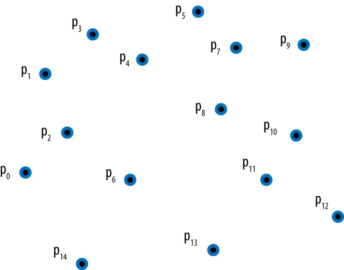
Figure 1-1. Sample set of 15 points in plane
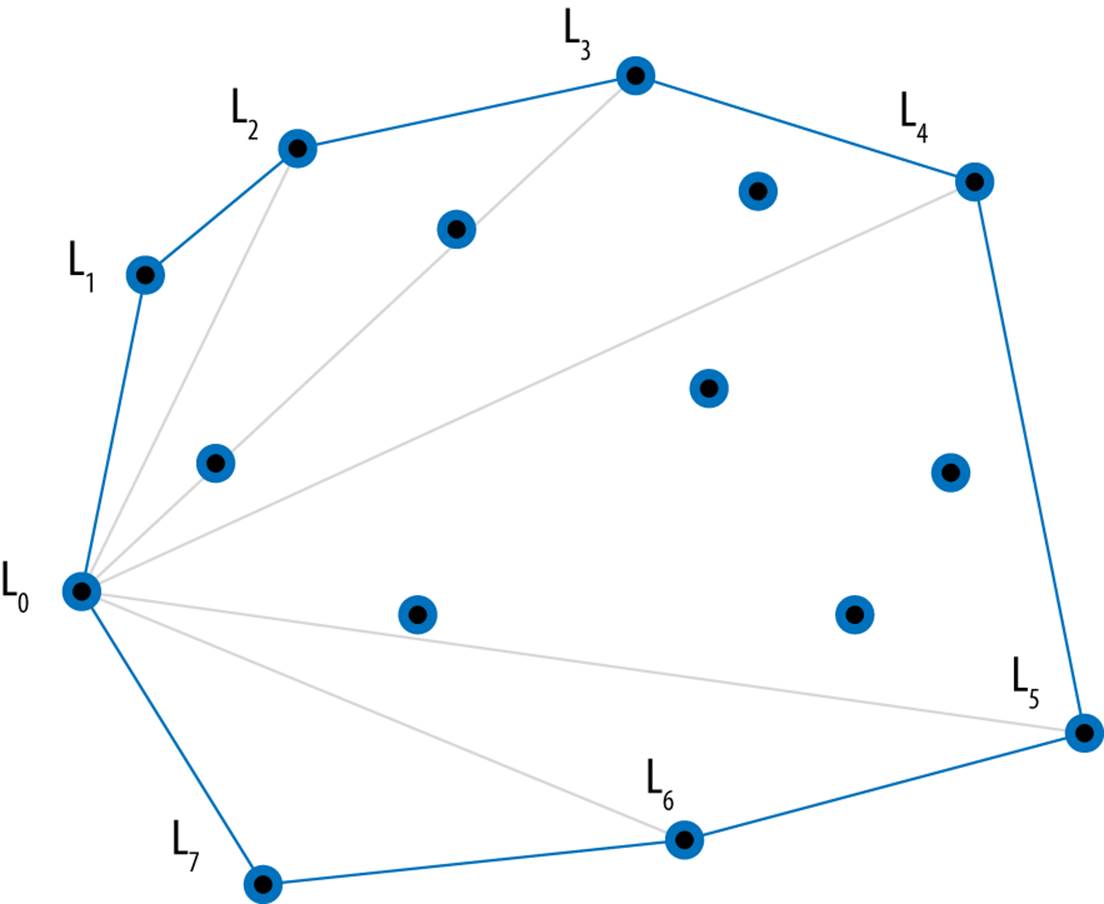
Figure 1-2. Computed convex hull for points
With just this information, you can probably draw the convex hull for any set of points, but could you come up with an algorithm (i.e., a step-by-step sequence of instructions that will efficiently compute the convex hull for any set of points)?
What we find interesting about the convex hull problem is that it doesn’t seem to be easily classified into existing algorithmic domains. There doesn’t seem to be any linear sorting of the points from left to right, although the points are ordered in clockwise fashion around the hull. Similarly, there is no obvious search being performed, although you can identify a line segment on the hull because the remaining n – 2 points are “to the right” of that line segment in the plane.
Naïve Solution
Clearly a convex hull exists for any collection of three or more points. But how do you construct one? Consider the following idea. Select any three points from the original collection and form a triangle. If any of the remaining n – 3 points are contained within this triangle, then they cannot be part of the convex hull. We’ll describe the general process using pseudocode, and you will find similar descriptions for each of the algorithms in the book.
SLOW HULL SUMMARY
Best, Average, Worst: O(n4)
slowHull (P)
foreach p0 in P do
foreach p1 in {P-p0} do
foreach p2 in {P-p0-p1} do ![]()
foreach p3 in {P-p0-p1-p2} do
if p3 is contained within Triangle(p0,p1,p2) then
mark p3 as internal ![]()
create array A with all non-internal points in P
determine leftmost point, left, in A
sort A by angle formed with vertical line through left ![]()
return A
![]()
Points p0, p1, p2 form a triangle.
![]()
Points not marked as internal are on convex hull.
![]()
These angles (in degrees) range from –90 to 90.
In the next chapter, we will explain the mathematical analysis that shows why this approach is considered to be inefficient. This pseudocode summary explains the steps that produce a convex hull for each input set; in particular, it created the convex hull in Figure 1-2. Is this the best we can do?
Intelligent Approaches
The numerous algorithms in this book are the results of striving for more efficient solutions to existing code. We identify common themes in this book to help you solve your problems. There are many different ways to compute a convex hull. In sketching these approaches, we give you a sample of the material in the chapters that follow.
Greedy
Here’s a way to construct the convex hull one point at a time:
1. Remove from P its lowest point, low, which must be part of the hull.
2. Sort the remaining n – 1 points in descending order by the angle formed in relation to a vertical line through low. These angles range from 90 degrees for points to the left of the line down to –90 degrees for points to the right. pn–2 is the rightmost point and p0 is the leftmost point.Figure 1-3 shows the vertical line and the angles to it from each point as light lines.
3. Start with a partial convex hull formed from three points in this order {pn–2, low, p0}. Try to extend the hull by considering, in order, each of the points p1 to pn–2. If the last three points of the partial hull ever turn left, the hull contains an incorrect point that must be removed.
4. Once all points are considered, the partial hull completes. See Figure 1-3.
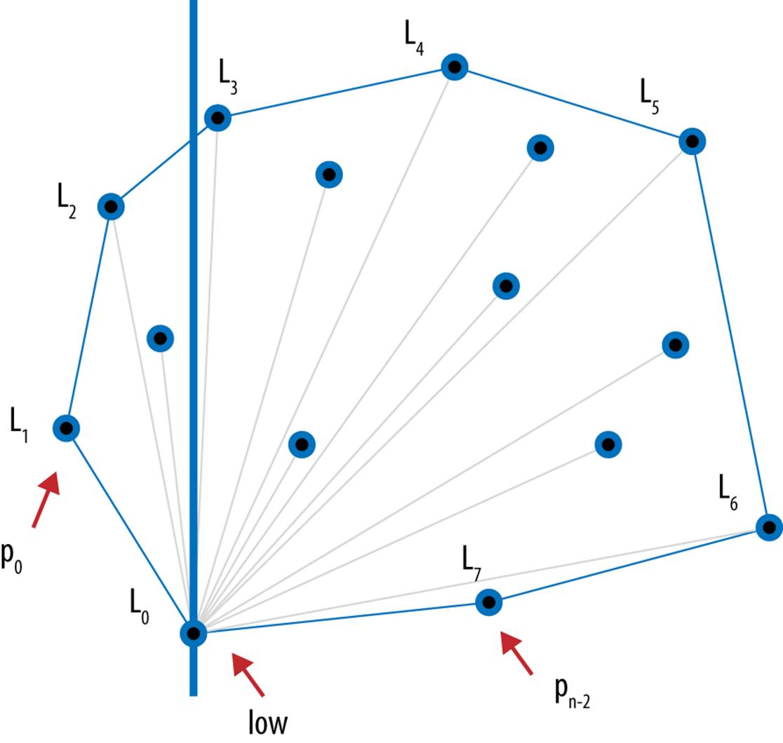
Figure 1-3. Hull formed using a Greedy approach
Divide and Conquer
We can divide the problem in half if we first sort all points, P, left to right by x coordinate (breaking ties by considering their y coordinate). From this sorted collection, we first compute the upper partial convex hull by considering points in order left to right from p0 to pn–1 in the clockwise direction. Then the lower partial convex hull is constructed by processing the same points in order right to left from pn–1 to p0 again in the clockwise direction. Convex Hull Scan (described in Chapter 9) computes these partial hulls (shown in Figure 1-4) and merges them together to produce the final convex hull.
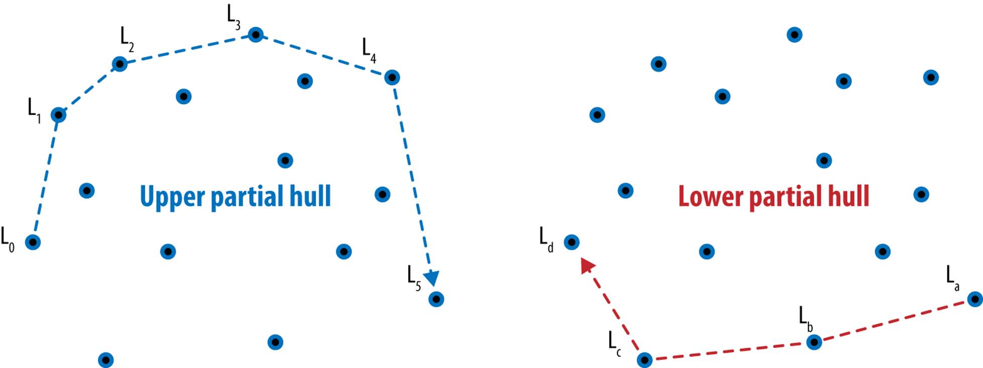
Figure 1-4. Hull formed by merging upper and lower partial hulls
Parallel
If you have a number of processors, partition the initial points by x coordinate and have each processor compute the convex hull for its subset of points. Once these are completed, the final hull is stitched together by the repeated merging of neighboring partial solutions. A parallel approach divides subproblems among a number of processors to speed up the overall solution.
Figure 1-5 shows this approach on three processors. Two neighboring hulls are stitched together by adding two tangent lines—one on the top and one on the bottom—and then eliminating the line segments contained within the quadrilateral formed by these two lines.
Approximation
Even with these improvements, there is still fixed lower bound performance for computing the convex hull that cannot be beaten. However, instead of computing the exact answer, perhaps you would be satisfied with an approximate answer that can be computed quickly and whose error can be accurately determined.
The Bentley–Faust–Preparata algorithm constructs an approximate convex hull by partitioning the points into vertical strips (Bentley et al., 1982). Within each strip, the maximum and minimum points (based on y coordinate) are identified (they are drawn in Figure 1-6 with squares around the points). Together with the leftmost point and the rightmost point in P, these extreme points are stitched together to form the approximate convex hull. In doing so, it may happen that a point falls outside the actual convex hull, as shown for point p1 in Figure 1-6.
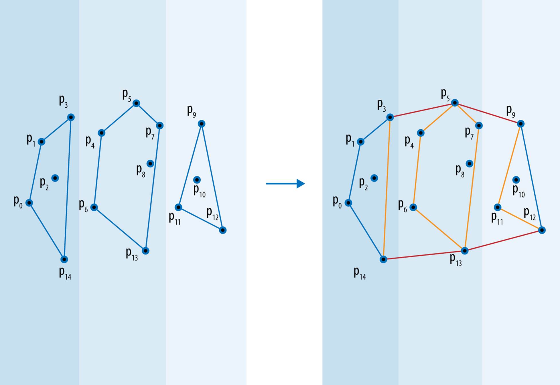
Figure 1-5. Hull formed by parallel constructions and stitching
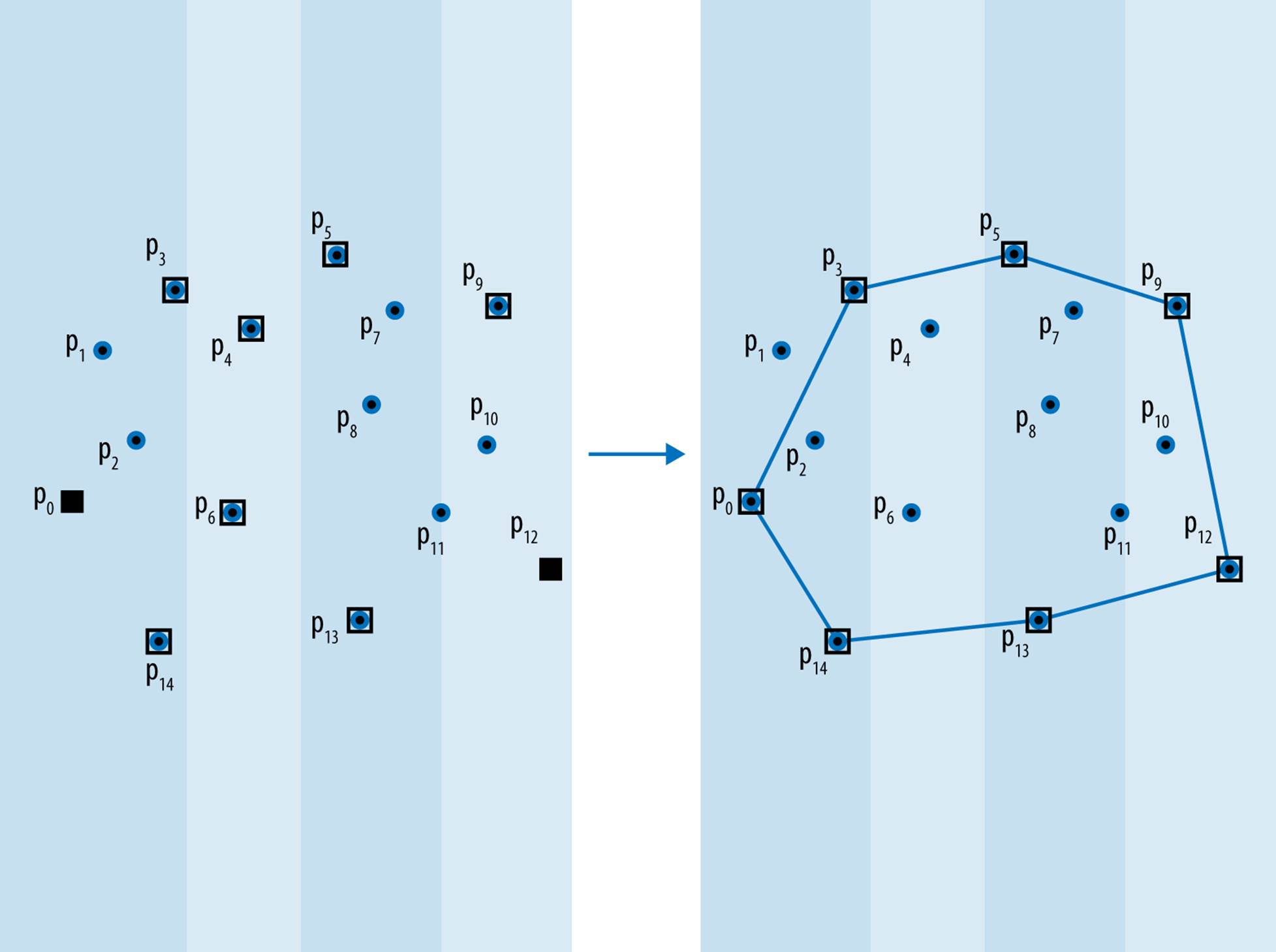
Figure 1-6. Hull formed by approximate computation
Generalization
It is often possible to solve a more general problem whose solution can be readily converted to solve your specific problem. The Voronoi diagram (Preparata and Shamos, 1993) is a geometric structure that divides a set of points in a plane into regions, each one of which is anchored by one of the original points in the input set P. Each region Ri is the set of points (x, y) in the plane closer to the anchor point, pi, than any other point in P. Once the Voronoi diagram is computed, these regions can be visualized as shown in Figure 1-7. The gray regions are semi-infinite and you can observe that these match directly to the points on the convex hull. This observation leads to the following algorithm:
1. Compute the Voronoi diagram for P.
2. Initialize the hull with the lowest point, low, in P and start at its associated region.
3. In clockwise fashion, visit the neighboring region that shares an infinitely long side and add that region’s anchor point to the hull.
4. Continue adding points until the original region is encountered.
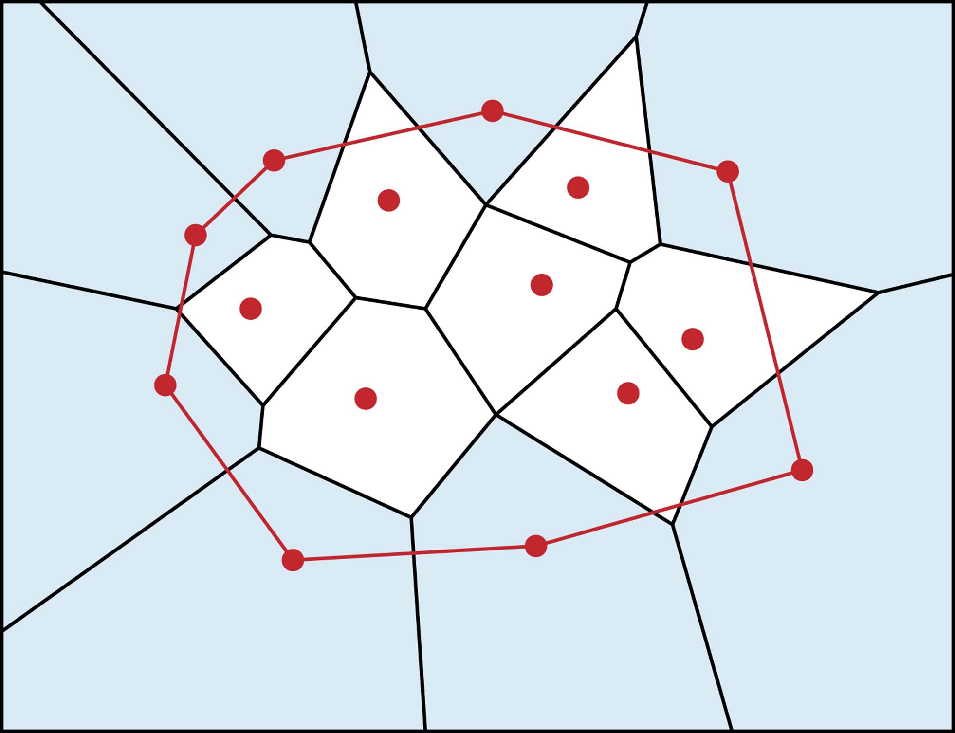
Figure 1-7. Hull computed from Voronoi diagram
Summary
An efficient algorithm is often not at all obvious to discover, and very different algorithms may be the best ones to choose for different data sets, different processing environments (such as where you can exploit parallelism), and different goals. This brief introduction only scratched the surface of algorithms. Hopefully you are now inspired to learn more about these different approaches as well as the variety of algorithms we have collected in this book. We have implemented all algorithms and provided suitable documentation and explanations to help you understand how to use these algorithms and even implement them yourselves.
References
Bentley, J. L., F. Preparata, and M. Faust, “Approximation algorithms for convex hulls,” Communications of the ACM, 25(1): 64–68, 1982, http://doi.acm.org/10.1145/358315.358392.
Preparata, F. and M. Shamos, Computational Geometry: An Introduction, Springer, 1993.
All materials on the site are licensed Creative Commons Attribution-Sharealike 3.0 Unported CC BY-SA 3.0 & GNU Free Documentation License (GFDL)
If you are the copyright holder of any material contained on our site and intend to remove it, please contact our site administrator for approval.
© 2016-2026 All site design rights belong to S.Y.A.