CCNP Security SISAS 300-208 Official Cert Guide (2015)
Part IV: Implementing Secure Network Access
Chapter 14. Deploying Guest Services
This chapter covers the following exam topics:
![]() Guest Services Overview
Guest Services Overview
![]() Configuring the Web Portal Settings
Configuring the Web Portal Settings
![]() Configuring the Sponsor Portal Policies
Configuring the Sponsor Portal Policies
![]() Managing Guest Portals
Managing Guest Portals
![]() Building Guest Authorization Policies
Building Guest Authorization Policies
![]() Provisioning Guest Accounts from the Sponsor Portal
Provisioning Guest Accounts from the Sponsor Portal
![]() Verifying Guest Access in ISE and the Network Access Device
Verifying Guest Access in ISE and the Network Access Device
So far, much of our focus has been on the admission of employees and trusted users onto the network. However, ISE is capable of much more than that. What should we do when we need to provide a user temporary access to the network, such as a visitor, consultant, customer, or contractor? How do we control the ability of a user to create these temporary accounts, and how do we control the level of access that is given to these temporary users?
In this chapter, you will learn how Cisco ISE supports these temporary visitors to the network—a feature referred to as Guest Services. You will learn how to configure the various portals and policies within ISE that are used by the sponsors of these temporary users.
In a similar manner, you will also configure the guest portals—the webpages whereby the guest will authenticate—and build the authorization policy that manages the guest user’s level of access that will follow this authentication.
To finish this chapter, you will provision a guest account using the configured sponsor portal and verify the guest’s access on the network access device.
“Do I Know This Already?” Quiz
The “Do I Know This Already?” quiz enables you to assess whether you should read this entire chapter thoroughly or jump to the “Exam Preparation Tasks” section. If you are in doubt about your answers to these questions or your own assessment of your knowledge of the topics, read the entire chapter. Table 14-1 lists the major headings in this chapter and their corresponding “Do I Know This Already?” quiz questions. You can find the answers in Appendix A, “Answers to the ‘Do I Know This Already?’ Quizzes.”
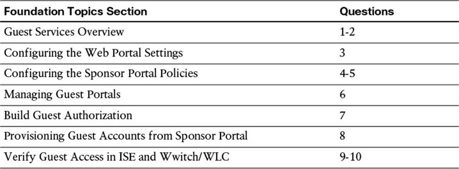
Table 14-1 “Do I Know This Already?” Section-to-Question Mapping
Caution
The goal of self-assessment is to gauge your mastery of the topics in this chapter. If you do not know the answer to a question or are only partially sure of the answer, you should mark that question as wrong for purposes of the self-assessment. Giving yourself credit for an answer you correctly guess skews your self-assessment results and might provide you with a false sense of security.
1. ISE Guest Services use which of the following approaches to authenticate a user?
a. Badge
b. WebAuth
c. TACACS+
d. SSH
2. The sponsor and guest portals can run on which of the following ISE personas?
a. Admin
b. MnT
c. PSN
d. a and b
e. a and c
f. b and c
3. True or False: A network administrator can customize the guest portals to run on any port greater than 1024.
a. True
b. False
4. Which default sponsor groups are available on ISE? (Select three.)
a. SponsorAllAccounts
b. SponsorADAccounts
c. SponsorAdministrator
d. SponsorGroupGrpAccounts
e. SponsorAllUsers
f. SponsorGroupOwnAccounts
5. When using Active Directory group membership as authentication and authorization for sponsors, which of the following must occur?
a. ISE must be associated to the domain.
b. The sponsor must create all guest accounts on the Active Directory Server.
c. The Active Directory identity store must be part of the identity source sequence for the sponsor portal.
d. a and b.
e. b and c.
f. a and c.
6. Under the Operations tab of the portal configuration page, which of the following items can be configured?
a. Guest Device Registration
b. Allow or Require Guest to change password
c. Guest Self-Service
d. Acceptable Use Policy frequency
e. All of the above
7. What are the three configurable options for a sponsor group?
a. Authorization Levels, Guest Roles, Time Profiles
b. Access-List, VLAN, Security Group Tag
c. Switch, Router, Firewall
d. Centralized WebAuth, Network Supplicant Provisioning, Device Registration Webpage
8. Which of the following are options for provisioning guest accounts on Cisco ISE?
a. Guest, Contractor, Consultant
b. OneDay, OneWeek, OneMonth
c. Individual, Import, Random
d. Full, Basic, InternetOnly
9. Which security policy must be enabled on the Guest WLAN/SSID to facilitate WebAuth on a Cisco WLC?
a. WPA2 with 802.1X Key Management
b. WPA2 with 802.1X and CCKM Key Management
c. MAC Filtering and RADIUS NAC
d. Open
10. To verify a guest user’s access policy on a Cisco switch, you should run which of the following commands?
a. show crypto ipsec sa
b. show aaa authorization <username> details
c. show authorization level guest interface <if_name>
d. show authentication sessions interface <if_name> details
Foundation Topics
Guest Services Overview
Cisco ISE can be flexible in its deployment, allowing network administrators to configure varying levels of access for a number of different user scenarios—such as for full-time employees and visitors alike. This section focuses on the configuration of Guest Services.
Guest Services and WebAuth
As you just learned, Guest Services is the ability for ISE to provide access to a temporary user. This temporary user could be one of the following:
![]() Visitor—Possibly the employee’s sick child who came to work with his mother. The mother might choose to provide the user basic Internet access so the child can watch cat videos all day.
Visitor—Possibly the employee’s sick child who came to work with his mother. The mother might choose to provide the user basic Internet access so the child can watch cat videos all day.
![]() Consultant—This user might need a slightly higher level of access than the child who is visiting his parent. However, we don’t want to give the consultant an unfettered level of access. This consultant’s access level may allow her to reach a few servers that are internal to the corporate network as well as access to the Internet.
Consultant—This user might need a slightly higher level of access than the child who is visiting his parent. However, we don’t want to give the consultant an unfettered level of access. This consultant’s access level may allow her to reach a few servers that are internal to the corporate network as well as access to the Internet.
![]() Contractor—This user, because he is acting as a temporary employee, can require the same amount of access as an employee—just for a shorter period of time.
Contractor—This user, because he is acting as a temporary employee, can require the same amount of access as an employee—just for a shorter period of time.
This temporary user will be added to the network by a trusted user, such as a network administrator, an employee, or a manager—and often allowed access to a finite set of network resources based on the sample use cases given previously.
As we discuss Guest Services, it is imperative that we also discuss Web Authentication (WebAuth). WebAuth is exactly like it sounds—the end user will use a webpage to authenticate, requiring only a valid username and password. Because you typically have no control over the hardware or software capabilities of a guest’s endpoint (the device might not support 802.1X or have no supplicant), WebAuth is well suited for guest services. How must we configure ISE and the network access device (NAD) to allow for this authentication? We discuss the specifics of the authentication and authorization process later in this chapter. In the meantime, we’ll briefly discuss the theory behind the Guest Services operation and how it interacts with the WebAuth function of ISE.
When a user first authenticates to the network, ISE issues the endpoint a very restrictive authorization profile (see Figure 14-1). This restrictive level of access provides the endpoint basic network connectivity—just enough to allow it to access ISE’s Guest Services web portal. As the user attempts to browse a website, he is redirected to ISE’s WebAuth portal. This WebAuth portal allows the user to provide login credentials—a pre-provisioned username and password. After authenticating via this web portal, ISE issues a Change of Authorization (CoA) to the NAD. This CoA forces a reauthorization of the endpoint on the NAD. Via this reauthorization process, ISE deploys a different authorization profile that provides the endpoint its final level of access. This level of access—in both the length and the content—can be as permissive or restrictive as necessary, commensurate with the use cases as defined in the company’s security policy and implemented on ISE.
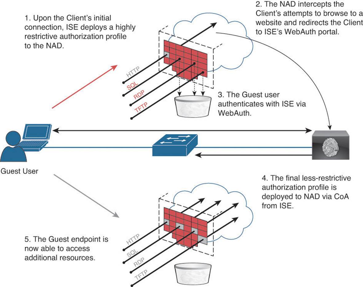
Figure 14-1 WebAuth process flow.
As we review the configuration of the Guest Services authorization policy later in this chapter, you will have a better understanding of what happens during these individual steps.
Portal Types
Cisco ISE has several portal types that we’ll leverage for Guest Services. The three major types of application portals as they relate to guest services are
![]() Admin portal—Shown in Figure 14-2, it allows the network administrator to configure sponsor and guest user policy.
Admin portal—Shown in Figure 14-2, it allows the network administrator to configure sponsor and guest user policy.
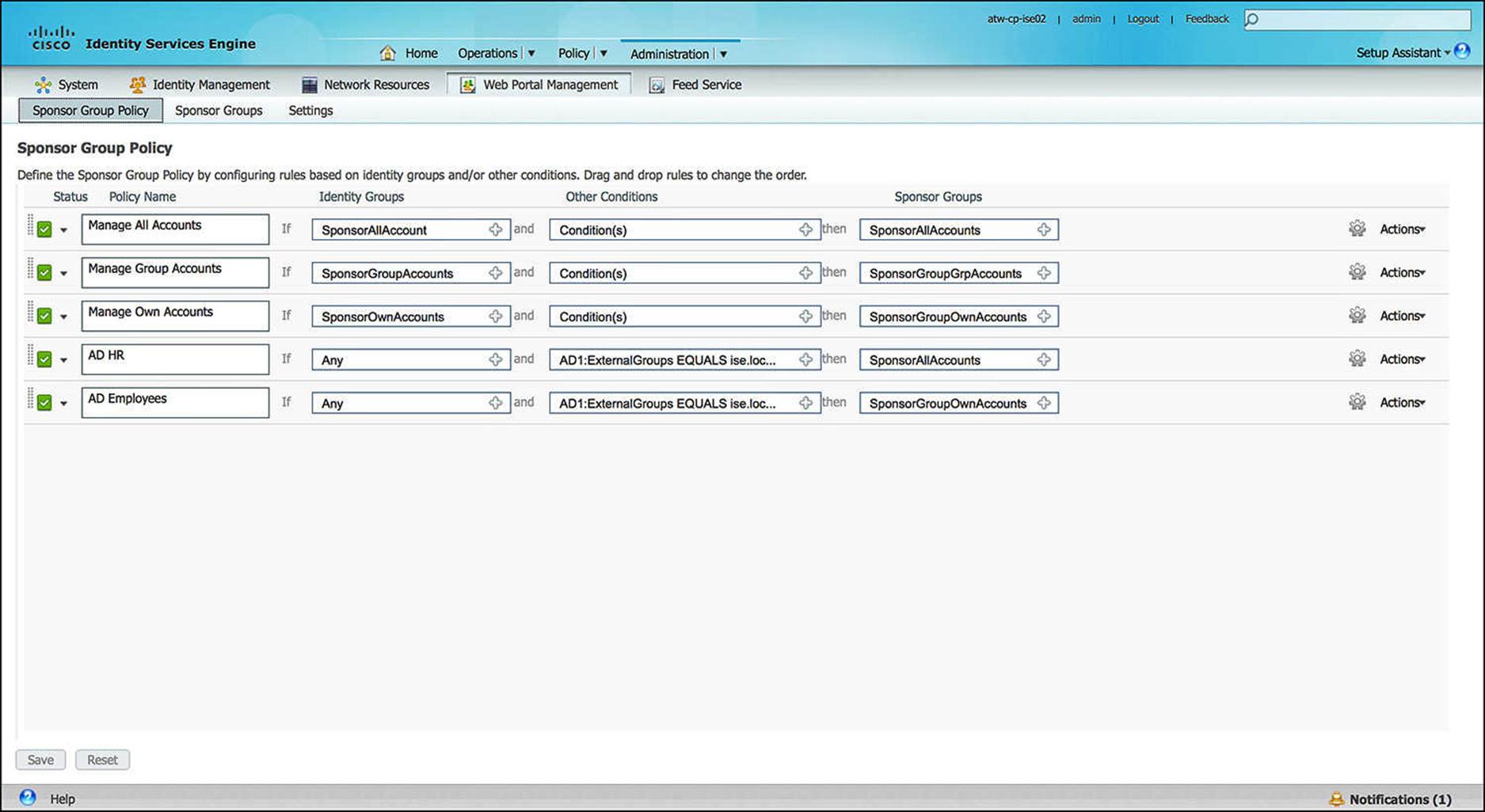
Figure 14-2 Admin portal.
![]() Sponsor portal—Shown in Figure 14-3, it allows the sponsor to manage guest user accounts.
Sponsor portal—Shown in Figure 14-3, it allows the sponsor to manage guest user accounts.
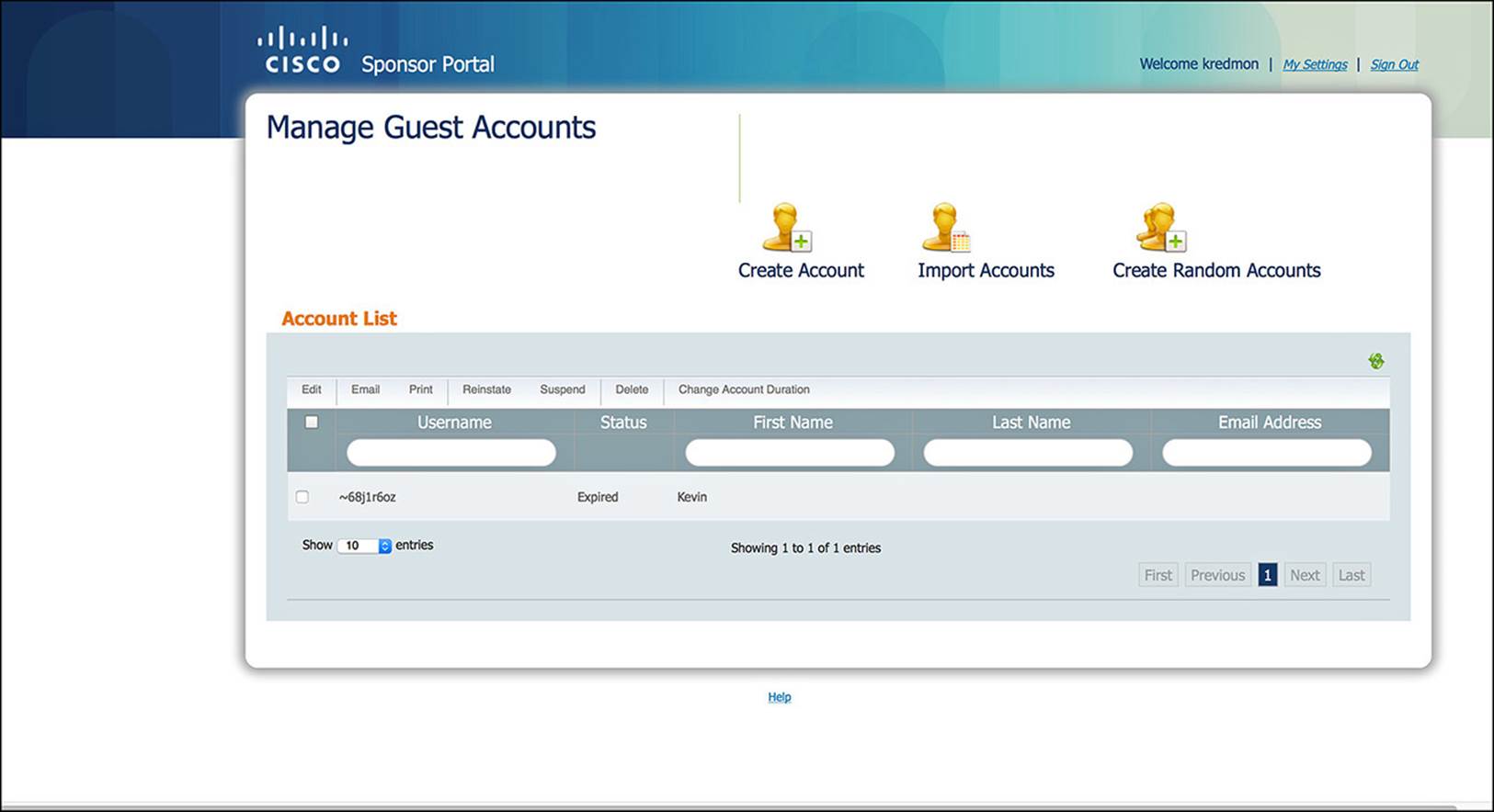
Figure 14-3 Sponsor portal.
![]() Guest user portal—Shown in Figure 14-4, it allows the guest user to log in.
Guest user portal—Shown in Figure 14-4, it allows the guest user to log in.
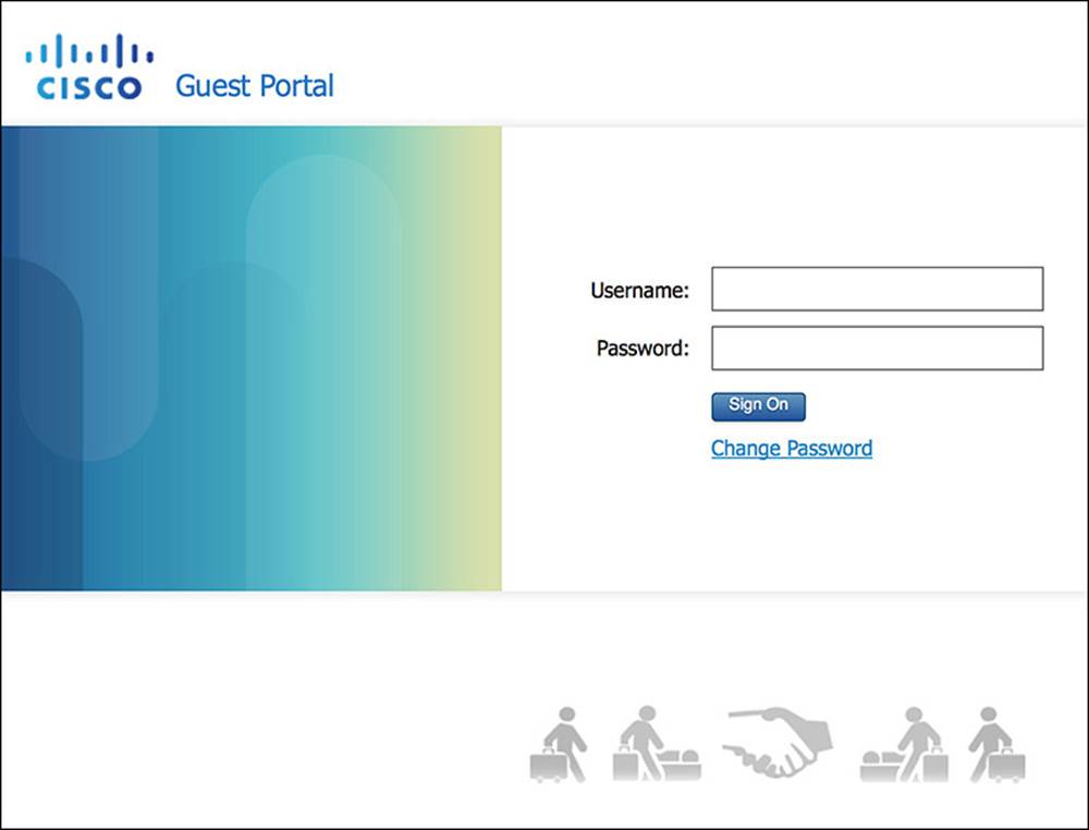
Figure 14-4 Guest user portal.
The guest user portal contains a number of elements, including these:
![]() Guest User Login screen—This screen within the guest portal prompts the user for a username and password field (see Figure 14-4). This is the authentication piece of WebAuth.
Guest User Login screen—This screen within the guest portal prompts the user for a username and password field (see Figure 14-4). This is the authentication piece of WebAuth.
![]() Acceptable Use Policy screen—This screen enables administrators to provide the end user the rules, regulations, and guidelines—the Terms of Use—for using the network (see Figure 14-5). The user might get this screen upon the first login only or each time she logs in. This is configurable and can be customized with the requisite Acceptable Use Policy for your organization.
Acceptable Use Policy screen—This screen enables administrators to provide the end user the rules, regulations, and guidelines—the Terms of Use—for using the network (see Figure 14-5). The user might get this screen upon the first login only or each time she logs in. This is configurable and can be customized with the requisite Acceptable Use Policy for your organization.
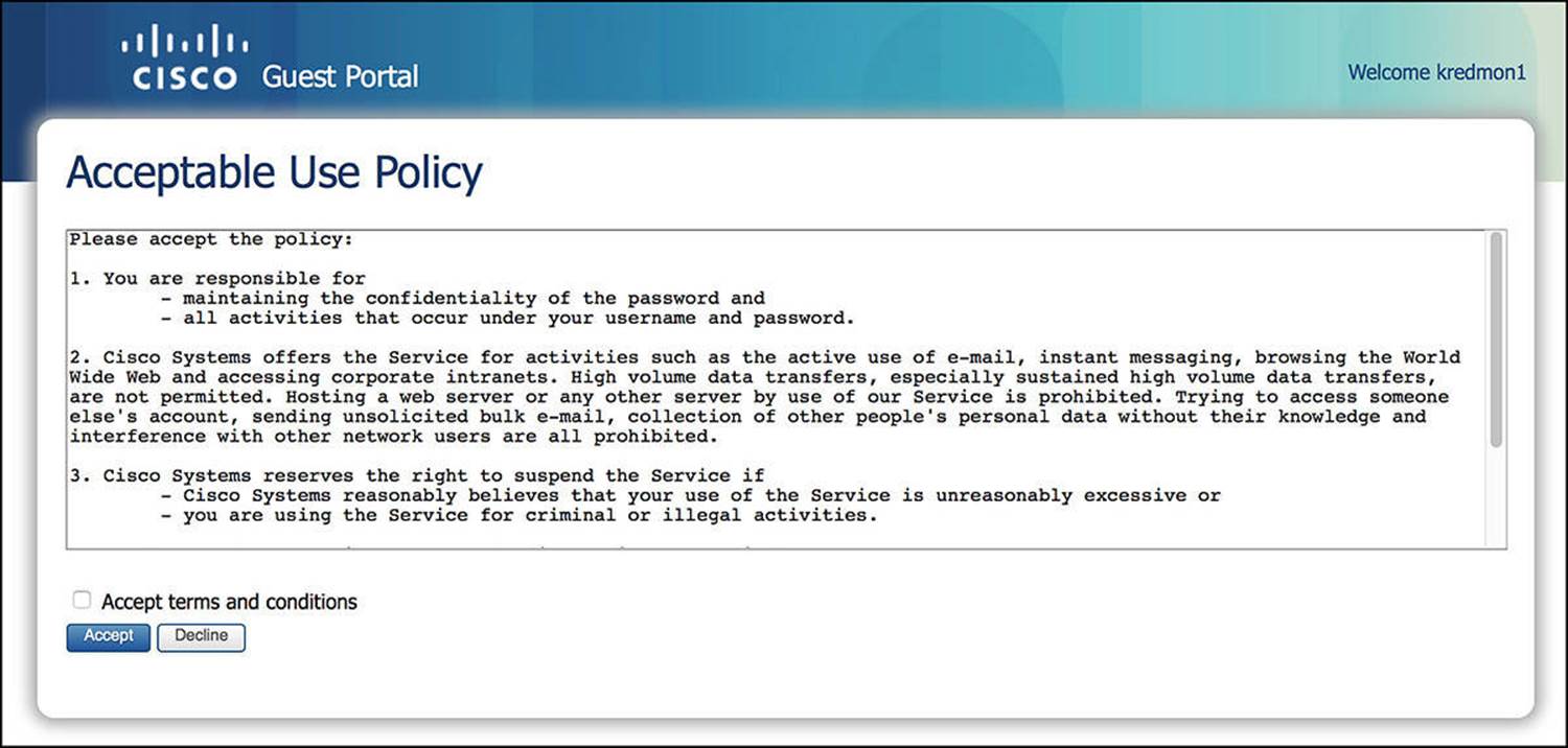
Figure 14-5 Acceptable Use Policy screen.
![]() Required Password Change screen—This screen requires the user to change the provided password. This can help ensure that the guest user can change the password to something that she knows as well as provide the guest user the option to change the password to something more private that only she knows—as the sponsor already knows the initial password that was issued. This is enabled by default.
Required Password Change screen—This screen requires the user to change the provided password. This can help ensure that the guest user can change the password to something that she knows as well as provide the guest user the option to change the password to something more private that only she knows—as the sponsor already knows the initial password that was issued. This is enabled by default.
![]() Allow Password Change screen—This screen allows the user to change the password if she chooses to (see Figure 14-6). If she clicks a Change Password link, this screen appears. This feature is enabled by default.
Allow Password Change screen—This screen allows the user to change the password if she chooses to (see Figure 14-6). If she clicks a Change Password link, this screen appears. This feature is enabled by default.
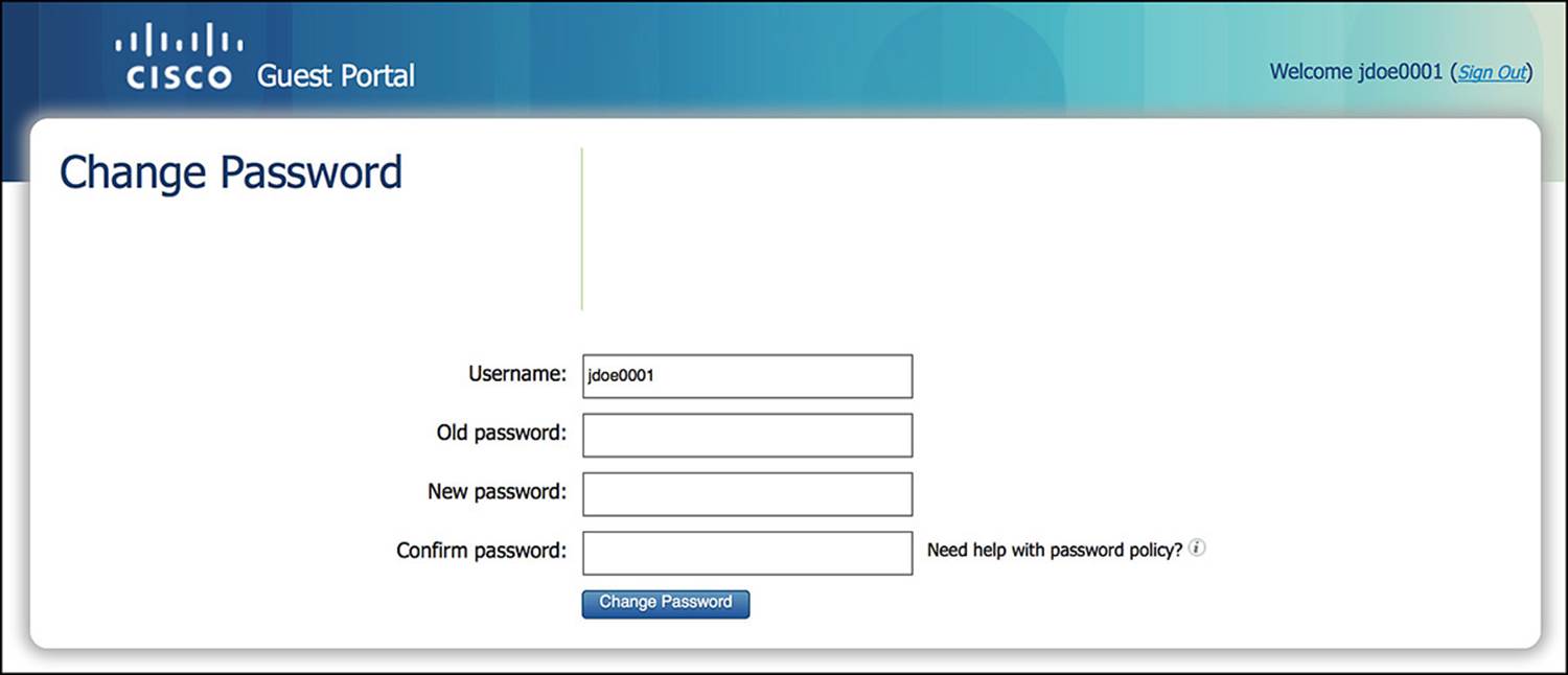
Figure 14-6 Required Password/Allow Password Change screen.
![]() Self-Registration screen—This screen is an optional screen that lets guests to set up their own accounts (see Figures 14-7 and 14-8).
Self-Registration screen—This screen is an optional screen that lets guests to set up their own accounts (see Figures 14-7 and 14-8).
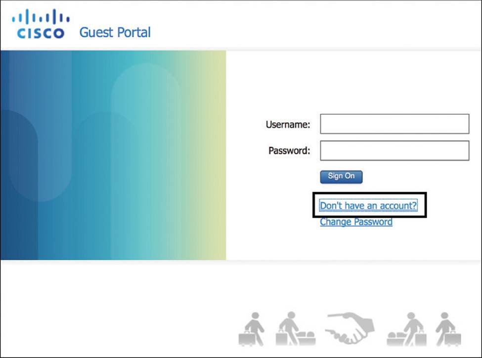
Figure 14-7 Self-Registration Login screen.
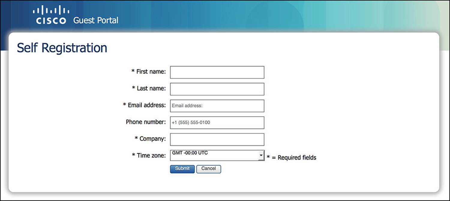
Figure 14-8 Self-Registration Creation screen.
To change whether the fields are optional, mandatory, or unused, you can go to Administration > Web Portal Management > Settings, Guest > Details Policy within the administration portal (see Figure 14-9). If you want to modify the Optional Data fields to be something more meaningful, you can do so by going to Administration > Web Portal Management > Settings > Sponsor > Language Template and choosing the appropriate language that should be modified. After selecting the appropriate language, you can now choose which sponsor portal page needs to be modified (for example, Configure Self Registration).
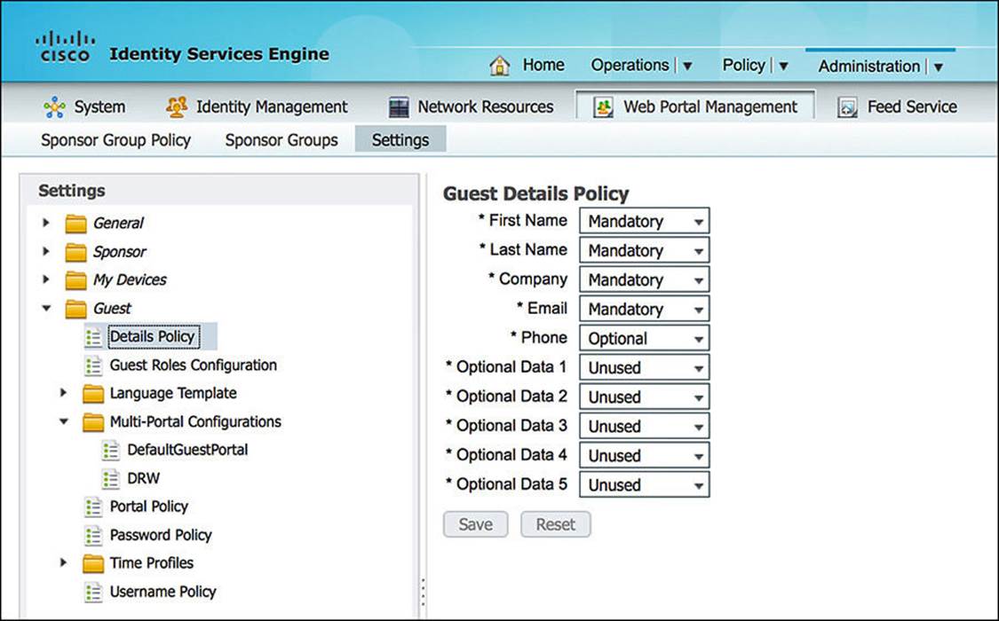
Figure 14-9 Self-Registration input field configuration.
![]() Device Registration screen—This screen enables a guest user to self-register a predefined number of endpoints by MAC address (see Figure 14-10). This registration results in static population of an internal endpoint identity database. The user requires valid credentials if she wants to register devices.
Device Registration screen—This screen enables a guest user to self-register a predefined number of endpoints by MAC address (see Figure 14-10). This registration results in static population of an internal endpoint identity database. The user requires valid credentials if she wants to register devices.
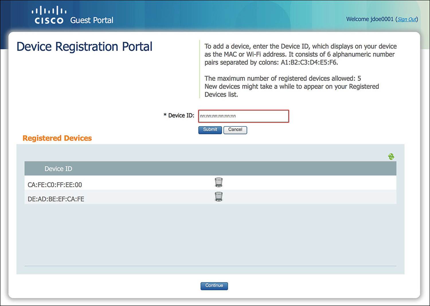
Figure 14-10 Device Registration screen.
Some of these elements can be optionally leveraged to customize the guest user’s experience as she joins the network.

In a distributed ISE deployment, the Admin portal runs exclusively on the Admin node. The sponsor and guest user portals run on those policy service nodes (PSNs) that are configured to run session services.
We discuss each of these portal types in more detail as we move along through this chapter.
Configuring the Web Portal Settings
Now that we know what each portal is capable of doing, we’ll walk through the configuration of many of these portals. The default configuration of the portals will often work fine for many deployments. However, we will provide a quick overview of several of the more common configuration options in case you choose to customize your deployment to match your company’s security policy.
The base configuration location to change the General Web Portal Settings within ISE is Administration > Web Portal Management > Settings > General. Expanding the General folder, you will see options for Portal Theme, Ports, and Purge (see Figure 14-11). We’ll be focusing mainly on the Ports configuration at this time.
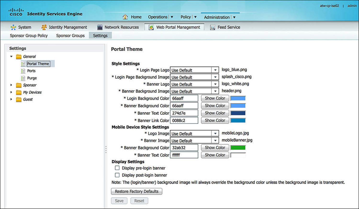
Figure 14-11 General web portal settings.
Port Numbers
As we discussed previously, ISE provides a number of portals to administrators, sponsors, and users alike, and many of these portals are central to the Guest Services Function. Starting with the base configuration location for the General Web Portal Settings, you will see an option for Ports(see Figure 14-12). These port settings enable you to modify the HTTPS ports that are used to access each portal on ISE. By default, these ports are all port 8443—except the Blacklist portal (which is port 8444). To change the port for a particular portal, simply change the port within the box to a value between 8000 and 8999 and then click Save.
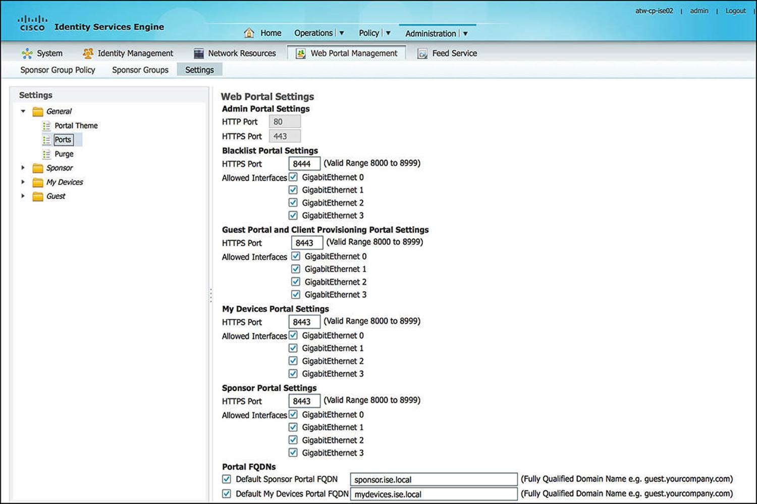
Figure 14-12 General Web Portal Settings – Ports.
Depending on your corporate security policy, you might choose to allow certain ports through your network by default or choose to block access to these ports from certain users or devices. By modifying the HTTPS port on which these portals reside, you have a greater amount of flexibility to provide certain users access to certain ports and portals while denying access to other users.
Again, the default configuration for these port settings will often work fine for many deployments.
Interfaces
While still under the Ports settings under the General Web Portal Settings (refer to Figure 14-12), you will also notice that you can enable or disable access to the individual portals on certain interfaces of the PSNs. Depending on the size and configuration of your ISE deployment, you can choose to allow access to the various portals on a number of interfaces. By enabling the portal on more interfaces, this can help you as you can now distribute the load across multiple interfaces.
From a security standpoint, for similar reasons to changing the HTTPS ports where the portals are hosted, you might choose to host a certain portal on a specific physical interface. For instance, you might elect to allow access to the sponsor portal out-of-band from the rest of your network. This would enable you to isolate the creation and management of guest accounts to computers on a management network.
Friendly Names
The Friendly Names configuration—again, still on the Ports configuration screen of the General Web Portal Settings (refer to Figure 14-12)—allows the administrator to simplify access to certain portals. As a sponsor, you will need to periodically access the sponsor portal to create guest user accounts. To make this account creation webpage easier to remember, you can configure a friendly name.
If you want to configure a Friendly Name for your sponsor portal, you can check the box beside Default Sponsor Portal FQDN and fill in the text box with the appropriate FQDN. For instance, a few good names for a sponsor portal might be sponsor.domain.com or guestaccounts.domain.com. This FQDN must be added to the relevant domain name service (DNS) servers for your organization, pointing to the appropriate interface Internet Protocol (IP) address(es) that are configured for the sponsor portal access. Also, because the sponsor portals are provided over HTTPS and leverage a X.509 certificate to authenticate the ISE portal server, it is imperative that you add the FQDN to the Subject Alternative Name of the portal’s X.509 certificate to minimize security warning pop-ups on your browser. Otherwise, without a properly constructed X.509 certificate by a trusted certificate authority (local or well-known), you can continually get untrusted server warnings as you access the sponsor and other ISE portals.
Besides the sponsor portal, you can also enable the friendly name for the My Devices Portal of ISE. End users can manage their registered devices via this My Devices Portal. For the lay user, it can be difficult to remember a long URL. If the user has just lost his endpoint or had it stolen, he might need to browse to the portal via a kiosk or a co-worker’s computer. An easy-to-remember URL will enable him to more quickly report his device as lost or stolen and minimize the risk of lost corporate intellectual property. A few examples of a My Devices FQDN would be mydevices.domain.com or byod.domain.com. The MyDevices portal is not one of the three portals required by Guest Services but is provided here for completeness.
The default URLs to access the common portals are listed in Table 14-2.


Table 14-2 Default URLs to Access the Common Portals
Configuring the Sponsor Portal Policies
ISE provides a great deal of flexibility in determining who can be a sponsor of guest user accounts. As an ISE administrator, you can define which users, if any, on your network can create a guest user account. The users given the privilege of creating guest accounts will be referred to assponsors. Depending on your corporate security policy, you can allow only certain users to create accounts for guests or can allow all full-time employees to create the guest accounts. As we’ll discuss shortly, the level of access given to a sponsor can vary depending on any number of factors.
To configure the sponsor portal policies, start at Administration > Web Portal Management > Settings > Sponsor. Expanding the Sponsor folder, you will see Authentication Source. This authentication source is an identity source sequence that ISE uses to authenticate sponsors as they attempt to log in. To configure the identity source sequence, go to Administration > Identity Management > Identity Source Sequences. You can add a new identity source sequence or modify the existing Sponsor_Portal_Sequence (see Figure 14-13). Any sponsor that will be creating guest users must be authenticated using one of the identity stores within the chosen identity source sequence (i.e., Sponsor_Portal_Sequence). For more information or to review identity source sequences, please refer to Chapter 9, “Initial Configuration of Cisco ISE.”
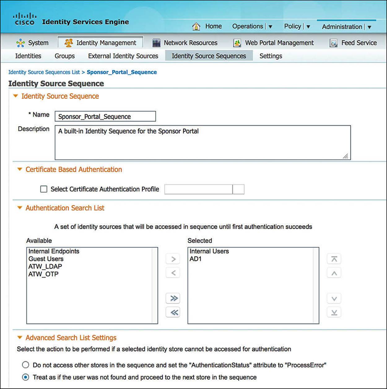
Figure 14-13 Sponsor_Portal_Sequence.
Sponsor Types
Sponsors can have varying levels of access, or capabilities, when it comes to creating guest users. ISE provides this flexibility in differentiating sponsors, as not all sponsors should be created equal. Earlier, we discussed that sponsors can be network administrators or full-time employees. Should all guest users created by either of these two groups of sponsors have the same level of access to network resources? Maybe, but probably not.
As a network administrator, you might have a better understanding of the level of security provided by the different guest user account types (which we’ll discuss more shortly). Furthermore a full-time employee might not be well versed on networking and might have no idea what network security even means.
To further highlight the need for different levels of sponsors, the guest accounts created by the two sponsor groups can have different purposes. A guest account created by an employee might be to allow Internet access for a day, week, or month. However, a guest account created by a network administrator might need to be semi-permanent and have a much greater level of access. For instance, a network administrator may be responsible for providing long term network access to contract employees, giving them full access to all corporate resources for a year or more. This is not a responsibility that you would normally give to just any employee. By allowing your sponsors to create guest user accounts, they are allowing, potentially, unfamiliar, dangerous people onto your network. These guest users might be innocent or they might be nefarious hackers trying to steal all your corporate secrets and sell them to a competitor. A network administrator might have a few additional resources to verify his guest users or might receive additional training to help ensure that the guest user is legit and not a criminal.
Now that we have a background as to why we need differentiation between sponsors, let’s take a look at how this is done. Within ISE, browse to Administration > Web Portal Management > Settings > Sponsor Groups (see Figure 14-14). Looking at the default configuration, you will notice that there are three different sponsor groups—SponsorAllAccounts, SponsorGroupGrpAccounts, and SponsorGroupOwnAccounts. These default groups and their associated policy provide the following sponsor access:
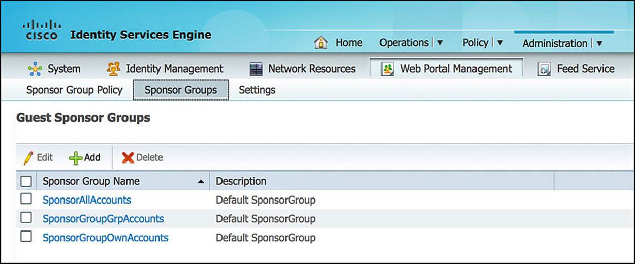
Figure 14-14 Sponsor groups.
![]() SponsorAllAccounts—These sponsors can manage all guest accounts on your ISE network.
SponsorAllAccounts—These sponsors can manage all guest accounts on your ISE network.
![]() SponsorGroupGrpAccounts—These sponsors can manage only guest accounts created by sponsor users from the same sponsor group.
SponsorGroupGrpAccounts—These sponsors can manage only guest accounts created by sponsor users from the same sponsor group.
![]() SponsorGroupOwnAccounts—These sponsors can manage only those guest accounts that they have created.
SponsorGroupOwnAccounts—These sponsors can manage only those guest accounts that they have created.
Opening any of these three groups, you will see that there are several tabs to configure and many useful options to consider.
![]() General—This is the name and a brief description of the sponsor group.
General—This is the name and a brief description of the sponsor group.
![]() Authorization Levels—This tab highlights what the sponsor can and cannot do (see Figure 14-15). For instance, a sponsor might be allowed to create random accounts, create accounts from a CSV file, send emails/SMS, and view the guests’ passwords, amongst other options.
Authorization Levels—This tab highlights what the sponsor can and cannot do (see Figure 14-15). For instance, a sponsor might be allowed to create random accounts, create accounts from a CSV file, send emails/SMS, and view the guests’ passwords, amongst other options.
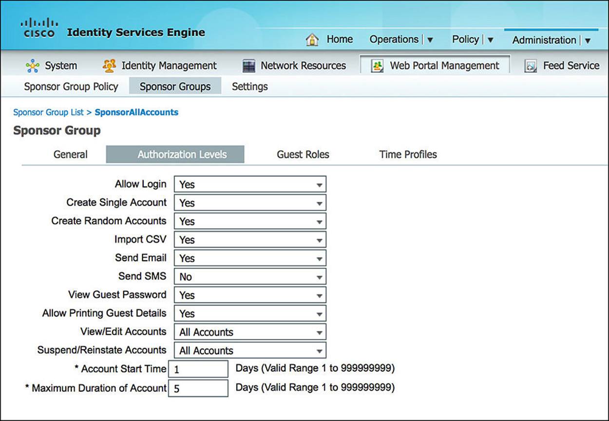
Figure 14-15 Authorization levels.
![]() Guest Roles—This tab shows what guest roles a sponsor can create (see Figure 14-16). These guest roles can eventually play a role in the level of access provided to the guest user. For instance, you might choose to create a guest role of Contractor (giving full access to the network on a temporary basis) or a Visitor (giving only Internet access to the guest user).
Guest Roles—This tab shows what guest roles a sponsor can create (see Figure 14-16). These guest roles can eventually play a role in the level of access provided to the guest user. For instance, you might choose to create a guest role of Contractor (giving full access to the network on a temporary basis) or a Visitor (giving only Internet access to the guest user).
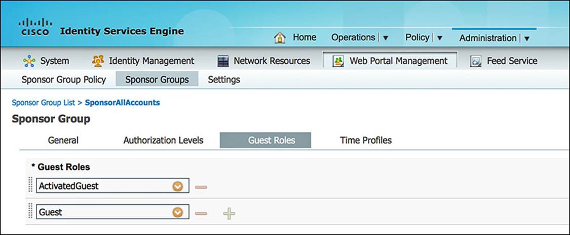
Figure 14-16 Guest roles.
![]() Time Profiles—This tab shows the length of time that a sponsor can allocate to a guest account (see Figure 14-17). These profiles are defined via Administration > Web Portal Management > Settings > Guest > Time Profiles (see Figure 14-18). Depending on the sponsor group, you can choose which time profiles are viable options.
Time Profiles—This tab shows the length of time that a sponsor can allocate to a guest account (see Figure 14-17). These profiles are defined via Administration > Web Portal Management > Settings > Guest > Time Profiles (see Figure 14-18). Depending on the sponsor group, you can choose which time profiles are viable options.
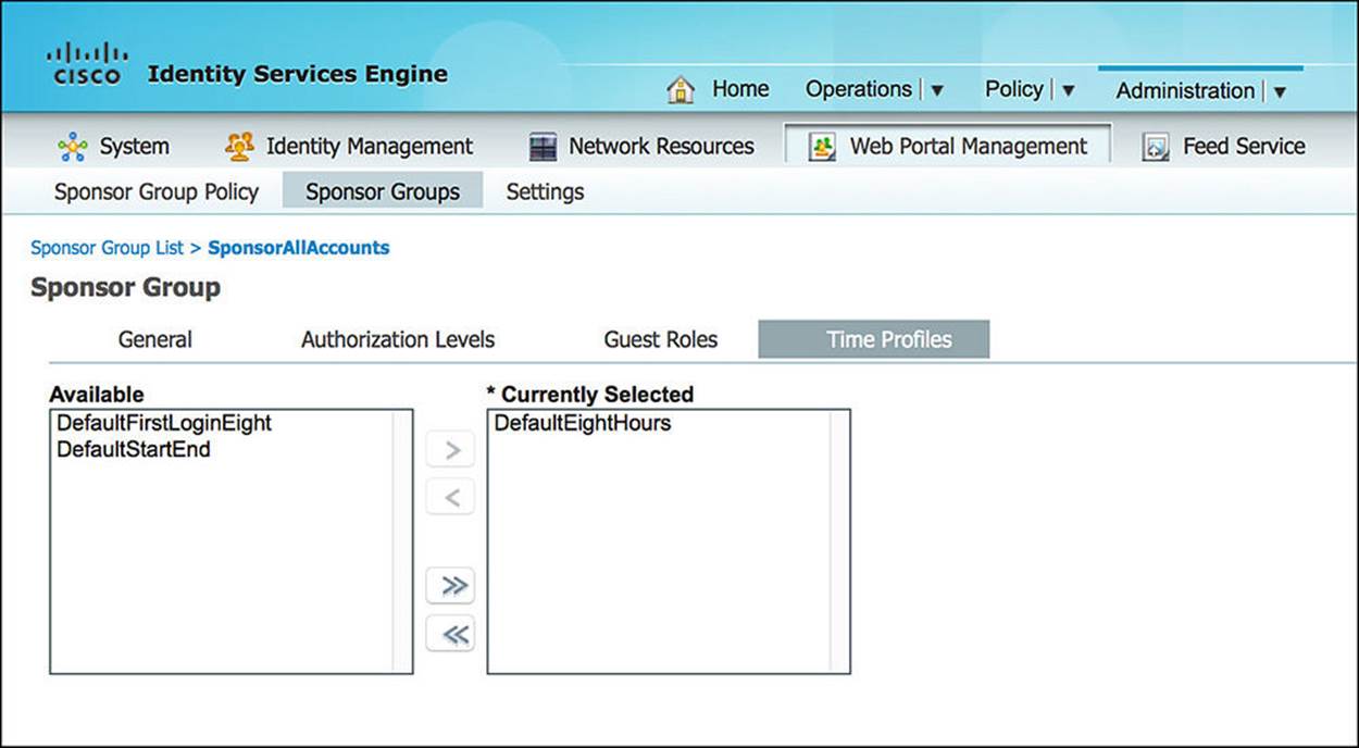
Figure 14-17 Time profiles.
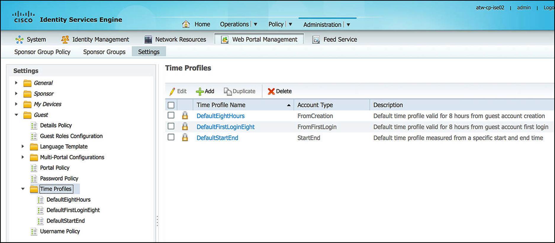
Figure 14-18 Time profiles definition.
Mapping Groups
Now that we have defined the sponsor groups and the groups’ capabilities, we must map these groups to the sponsors who will create the guest user accounts. The manner in which this mapping happens is similar to the IF-THEN constructs we used in defining authentication and authorization policies.
To configure this sponsor-to-group mapping, go to Administration > Web Portal Management > Settings > Sponsor Group Policy (see Figure 14-19).
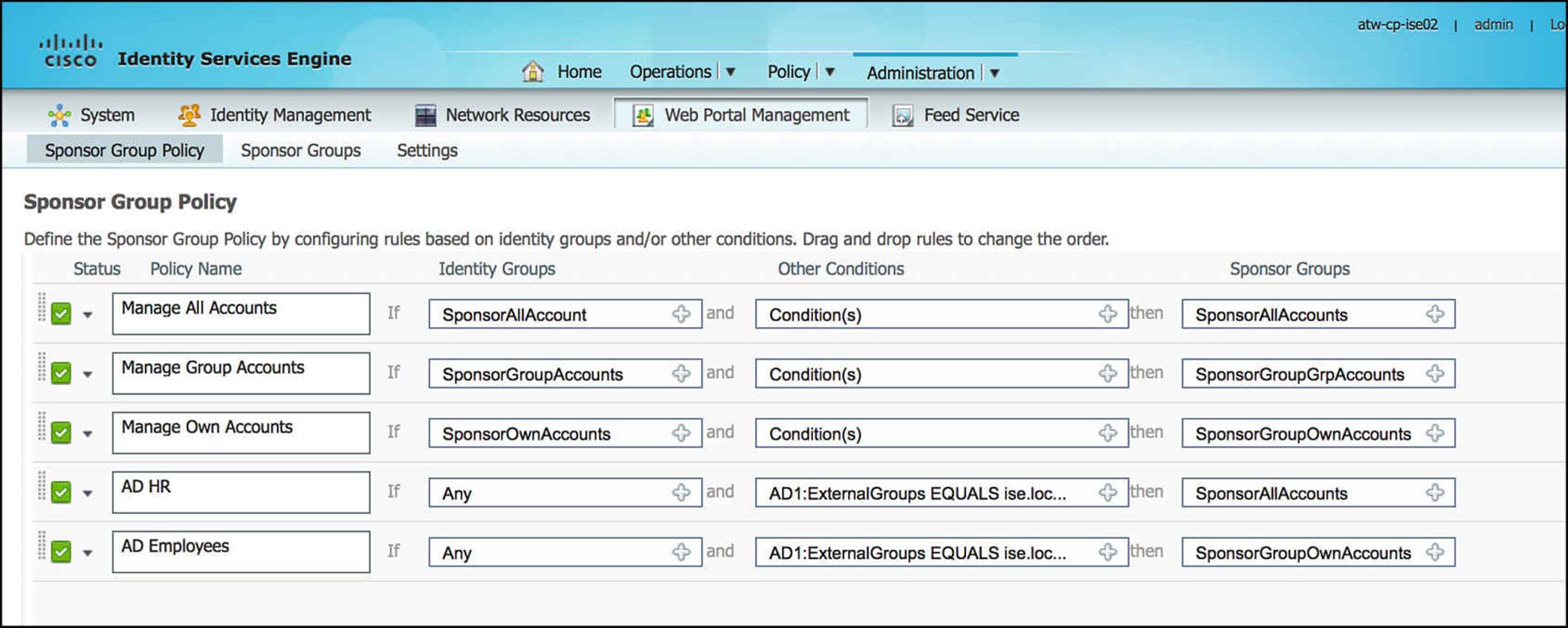
Figure 14-19 Sponsor group policy.
Looking at this policy, the first three rules are the default rules that are preconfigured on ISE. In each of these rules, you will see that the only condition governing the access provided to the sponsor is what ISE identity group that user is a part of. These three identity groups are also predefined on ISE. For any user to create user accounts via these first three rules, the usernames and passwords must be defined within ISE’s User Identity store at Administration > Identity Management > Identities > Users. A user can be associated to a number of user groups.
Managing a separate sponsor database on ISE for every employee could quickly become cumbersome, especially if you already have an identity management system that is centralized for your corporation. For that reason, ISE can leverage an external identity management system, such as Microsoft Active Directory, to manage the users for you. The last two sponsor group policy rules have been added to demonstrate this concept.
The first added rule, named AD HR, has no ISE identity group assigned with the rule. The condition, however, references an externally defined AD group—AD1:ExternalGroups EQUALS ise.local/Users/HR. Because these users are members of our human resources (HR) department, we want to allow HR to create and manage all guest user accounts. This results in the HR user being assigned to the sponsor group SponsorAllAccounts. As we discussed previously, this high level of access could provide HR the ability to create or delete guest user accounts for contractors or others, regardless of which employee or network administrator created the account.
The second added rule, named AD Employees, similarly does not have an ISE identity group assigned with the rule. The condition does reference an externally defined AD group: AD1:ExternalGroups EQUALS ise.local/Users/Employees. As we don’t want one employee to delete the user accounts of other employees, we have chosen to assign this group of users to the sponsor group SponsorGroupOwnAccounts. Therefore, the employee can edit or delete only those accounts that she personally created.
For these last two rules to be effective, allowing the designated employees to create the guest accounts, we’ll need to ensure that AD1 is added to the Sponsor_Portal_Sequence, as demonstrated in Figure 14-20.
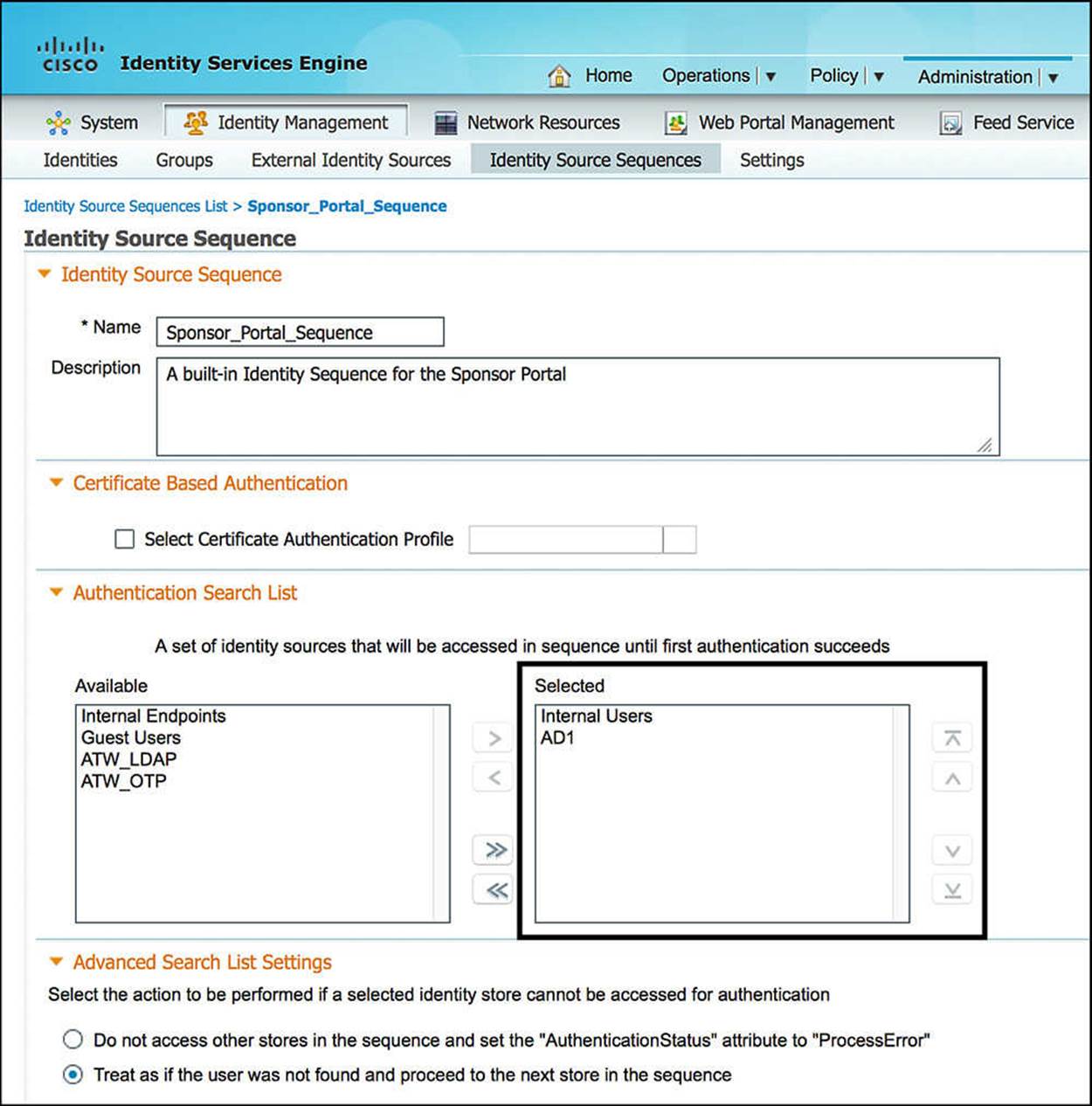
Figure 14-20 Add AD1 to Sponsor_Portal_Sequence.
Guest User Types
As a sponsor creates a guest user account, the user account can be assigned to any guest role or ISE identity group, as we previously mentioned in the Sponsor Types section. These guest roles, via the configuration Administration > Web Portal Management > Settings > Guest > Guest Roles Configuration, must be assigned to one of two guest user types—Guest or ActivatedGuest. By default, every ISE identity group is assigned to the guest user type of Guest.

What is the difference between Guest and ActivatedGuest? A guest user must authenticate via the Guest Services web portal. An ActivatedGuest can choose to authenticate to the network either via Guest Services web portal or use his credentials to authenticate to the network using 802.1X.
Managing Guest Portals
As you leverage the Guests Services functionality of Cisco ISE, you might decide that you would like to customize the guest user experience, possibly adding company branding or modifying color schemes. If you want to add your own company branding, this can be done via theAdministration > Web Portal Management > Settings > General > Portal Theme.
Portal Types
If you would rather customize a portal, you can do so by modifying an existing portal or by uploading complete HTML pages that are specific to your organization. This can be done via Administration > Web Portal Management > Settings > Guest > Multi-Portal Configurations (seeFigure 14-21). As you browse to this configuration menu, you will see that there is a DefaultGuestPortal. The DefaultGuestPortal is the standard guest portal that comes predefined on ISE. You can choose to modify this guest portal or create a custom portal from scratch, modifying the configuration and pages as you wish.
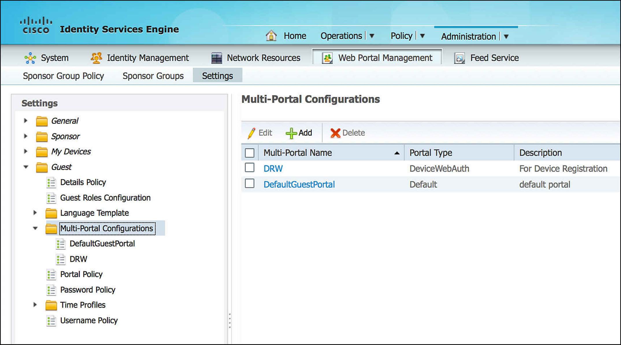
Figure 14-21 Multiportal configurations.
If you elect to create a custom portal from scratch, select Add from the Multi-Portal Configurations menu. As you click Add, you will be prompted to create a default portal or device web authorization portal—with each of these options allowing the administrator to select a customization template or to upload the HTML files. If you elect to upload HTML, you will be asked to map the HTML files with the specific ISE guest portal function, such as Login, Acceptable Use Policy (AUP), and so on.
Many of the customization options for a custom guest web portal are found on the Operations tab of the portal configuration. On this tab, you can choose whether the user will receive the Acceptable Use Policy (AUP) every time he logs in, only on the first login, or never receive the AUP at all. You can also allow a guest user to change his passwords as he wants, or you might choose to force a password change after the initial login. Equally important, a portal can allow a guest user to self-provision, self-service, and do device registration. Each of these options are unique to each custom portal you create, allowing a different visual experience as well as enabling only those features that are needed for each guest user scenario.

If you create a new guest portal, you will select this new portal as part of the authorization profile that is pushed to the endpoint upon successful authentication. We discuss the configuration of guest access policy later in this chapter.
Depending on your company’s security policy, you also can choose to modify the guest user username or password policies. By going to Administration > Web Portal Management > Settings > Guest > Password Policy (see Figure 14-22) or Administration > Web Portal Management > Settings > Guest > Username Policy (see Figure 14-23) within the ISE admin portal, you will see that you can define minimum guest user password requirements or username requirements. These requirements would define the character sets and quantities of each character class that must be used in a password or username, accordingly.
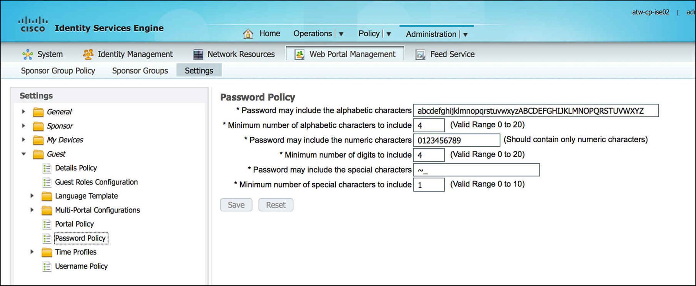
Figure 14-22 Guest user password policy.
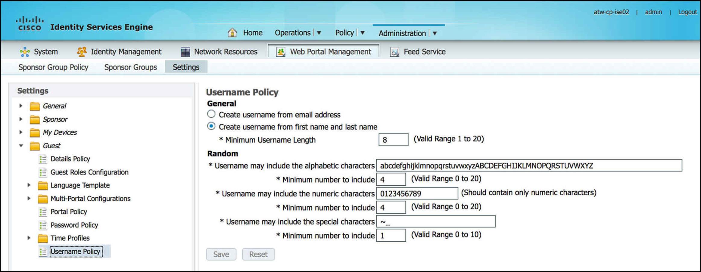
Figure 14-23 Guest user username policy.
Building Guest Authorization Policies
Before we configure guest authorization, let’s take a look at what happens during the authentication process for Guest Services (see Figure 14-24). When we look at the authentication policy on ISE, we will see that the first authentication rule configured is named MAB—using the Internal Endpoints identity store. This MAB policy is leveraged to authenticate users for Guest Services.
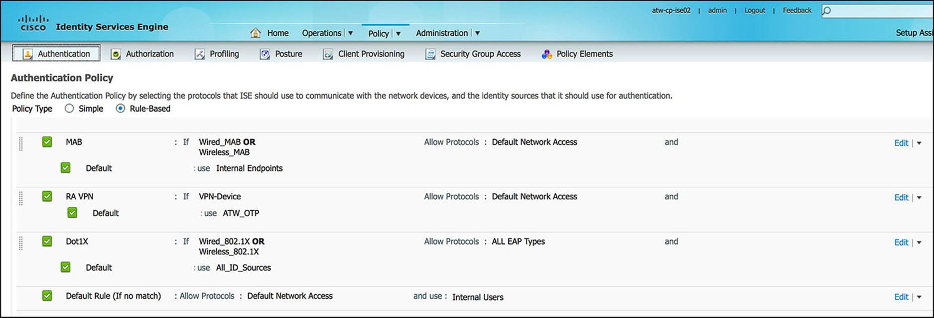
Figure 14-24 Authentication policy.
This MAB authentication policy is used only if one of the following conditions is met:
![]() Wired_MAB = Radius:Service-Type = Call Check AND Radius:NAS-Port-Type = Ethernet
Wired_MAB = Radius:Service-Type = Call Check AND Radius:NAS-Port-Type = Ethernet
![]() Wireless_MAB = Radius:Service-Type = Call Check AND Radius:NAS-Port-Type = Wireless - IEEE 802.11
Wireless_MAB = Radius:Service-Type = Call Check AND Radius:NAS-Port-Type = Wireless - IEEE 802.11
Another authentication rule that deserves to be mentioned is the 802.1X authentication rule—Dot1X. The Dot1X uses the All_ID_Sources identity store. This Dot1X policy is met with either of the compound conditions:
![]() Wired_802.1X = Radius:Service-Type = Framed AND Radius:NAS-Port-Type = Ethernet)
Wired_802.1X = Radius:Service-Type = Framed AND Radius:NAS-Port-Type = Ethernet)
![]() Wireless_802.1X = Radius:Service-Type = Framed AND Radius:NAS-Port-Type = Wireless—IEEE 802.11)
Wireless_802.1X = Radius:Service-Type = Framed AND Radius:NAS-Port-Type = Wireless—IEEE 802.11)
Finally, the Default authentication rule—chosen if none of the other policies match—uses the Internal Users identity store. Currently, the RA VPN policy does not have an impact on Guest Services.
As a NAD attempts to authenticate a user or an endpoint, there might be an authentication failure. With authentication, it is equally important for us to understand ISE’s behavior during an authentication failure as it is to understand an authentication success. There are several ways that an authentication failure can occur. The authentication failures that ISE can explicitly handle are
![]() Authentication Failed—ISE received an explicit response that authentication has failed, for example due to bad credentials, a disabled user, and so on. The default course of action is reject.
Authentication Failed—ISE received an explicit response that authentication has failed, for example due to bad credentials, a disabled user, and so on. The default course of action is reject.
![]() User not found—No such user was found in any of the identity databases. The default course of action is reject.
User not found—No such user was found in any of the identity databases. The default course of action is reject.
![]() Process failed—Unable to access the identity database or databases. The default course of action is to drop.
Process failed—Unable to access the identity database or databases. The default course of action is to drop.
Within ISE, you have the ability to choose how to react to these authentication failures. This functionality enables you to continue to the authorization step, despite a failure during the authentication process. The possible courses of action that ISE can take in case of an authentication failure are
![]() Reject—A reject response is sent.
Reject—A reject response is sent.
![]() Drop—No response is sent.
Drop—No response is sent.
![]() Continue—Cisco ISE continues with the authorization policy.
Continue—Cisco ISE continues with the authorization policy.

Even when you choose the Continue option, there might be restrictions on the protocol whereby Cisco ISE cannot truly continue. However, Continue is a viable option for PAP/ASCII, EAP-TLS, and MAC Authentication Bypass (MAB). For all other authentication protocols—those that cannot truly continue—an ACCESS_REJECT response is sent if there is an authentication failure or if the user or host is not found in the identity database. Otherwise, it drops the request and sends no response if the process fails. We discuss how we will leverage the authentication failures within the WebAuth process in more detail shortly.
Now that we understand the current authentication configuration on ISE, let’s take a look at WebAuth from the standpoint of the endpoint device. Because guest users can use several devices with different operating systems and capabilities, we cannot assume that all these guest users’ devices can support 802.1X. However, it is reasonable to expect that all guest devices that need network access have a web browser that can be used for authentication.
As the end user attempts to access the network, the NAD, as we configured it in Chapter 12, “Implement Wired and Wireless Authentication,” attempts to authenticate the user by trying 802.1X first and then MAB next and forwarding this information back to ISE. As the guest’s endpoint does not have an 802.1X supplicant, credentials, or configuration to authenticate to the network, the NAD’s attempts to authenticate the endpoint using 802.1X times out. The NAD then tries to authenticate the user and endpoint via MAB—the second method on the NAD’s authentication list configuration.
As we discussed in Chapter 6, “Introduction to Advanced Concepts,” and Chapter 12, MAB requires that the endpoint’s MAC address already exists in the endpoint identity store. Because this device is likely unknown to the network, this too will fail authentication. In this case, we are actually anticipating the authentication failure and will structure our authentication policy accordingly to handle this failure. To accommodate this anticipated failure and allow the authorization policy to provide the appropriate security policy, we will set the authentication failure reaction forIf user not found and If process failed to Continue (see Figure 14-25).
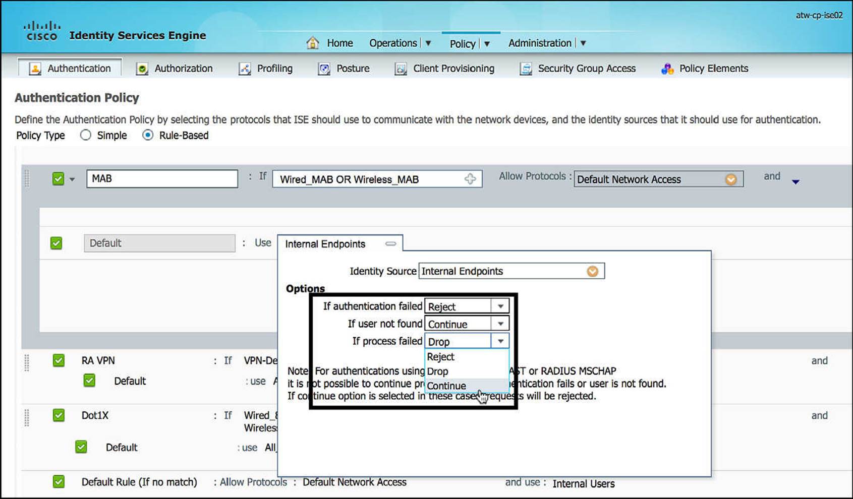
Figure 14-25 Changing authentication failure policies If User Not Found and If Process Failed to Continue.
Let’s walk through a play-by-play of what will happen with MAB, considering the changes we made on ISE. With the policy configured the way it is, anytime ISE attempts to authenticate an endpoint using MAB, one of two scenarios will play out:
![]() The endpoint’s MAC address is present in the Internal Endpoints or other identity store(s)—depending on the acceptable identity stores per the MAB authentication policy.
The endpoint’s MAC address is present in the Internal Endpoints or other identity store(s)—depending on the acceptable identity stores per the MAB authentication policy.
![]() The endpoint’s MAC address is NOT present in any of the elected endpoint identity store(s).
The endpoint’s MAC address is NOT present in any of the elected endpoint identity store(s).
In the first scenario, the endpoint’s MAC address is sent as the username for the Radius:Service-Type = Call Check ACCESS_REQUEST. The endpoint can be a member of an explicit endpoint identity list, such as a printer, an IP phone, or a copier MAB list, causing the authentication to pass, moving onto the authorization policy. The resulting authorization policy for an explicit MAB authentication success can be structured to allow the printer, the IP phone, copier, or another device access to a finite list of specific resources. Therefore, the final level of access is determined by the authorization policy on ISE.
In the second scenario, the endpoint’s MAC address is still sent as the username for the Radius:Service-Type = Call Check ACCESS_REQUEST. However, the endpoint will not be found in any of the configured endpoint identity stores. By default, this would result in an immediate authentication failure and an ACCESS_REJECT. With the If user not found being changed from Reject to Continue, the endpoint will still be allowed to continue with the authorization step. It is our responsibility, by our changing If user not found to Continue, to appropriately configure the authorization policy and only allow the device an appropriate level of access. We do not want this change to open the network to any unwanted network traffic.
Ultimately, with this new configuration, anytime the MAB rule is hit, ISE will “pass” authentication and all endpoints will move onto the authorization step. Theoretically, you could choose to configure the Default authentication rule’s If user not found setting to be Continue and it could serve the same purpose as this MAB rule. However, by explicitly mentioning MAB within the authentication rules, it provides the network administrator a more granular approach to handle a larger number of scenarios.
It is a best practice to handle all expected scenarios explicitly and fail closed otherwise. For this reason, it is best to set the Default authentication rule to Deny, resulting in ACCESS_REJECT for authentication failures or user not found scenarios, dropping the authentication request if the process fails.
We’ve now established that we will always move onto the authorization step when using MAB to accomplish Guest Services. Within the authorization step, we can now differentiate those scenarios where the device was found in the endpoint identity stores and those scenarios where the device was not found. This is usually handled by appropriately managing the order of the authorization rules or by electing the conditions of the authorization rules to set apart one MAB authorization from the others.
As was the case with the authentication process, it is a best practice to handle all expected authorization scenarios explicitly and then have a default rule whereby this default rule is as secure as reasonably possible. Often, this final rule will be a RADIUS ACCESS_REJECT response, such as the DenyAccess authorization profile, that denies all traffic from the endpoint.
Figure 14-26 shows this approach. Within the authorization policy, the identity groups are provided in bold typeface. Whenever an identity group is listed, it can be accompanied with other authorization conditions or by itself. In Figure 14-26, you will see that the DRW-Endpoints will be given the authorization profile of Internet_Only AND GUEST. The only condition present in this authorization rule is an endpoint identity group, implying that MAB alone is being used to authenticate this endpoint. The goal of this rule is to check the identity list DRW-Endpoints and, if the endpoint’s MAC address is present, provide the endpoint with the access given in the authorization profile Internet_Only and the SGT policy given by GUEST.
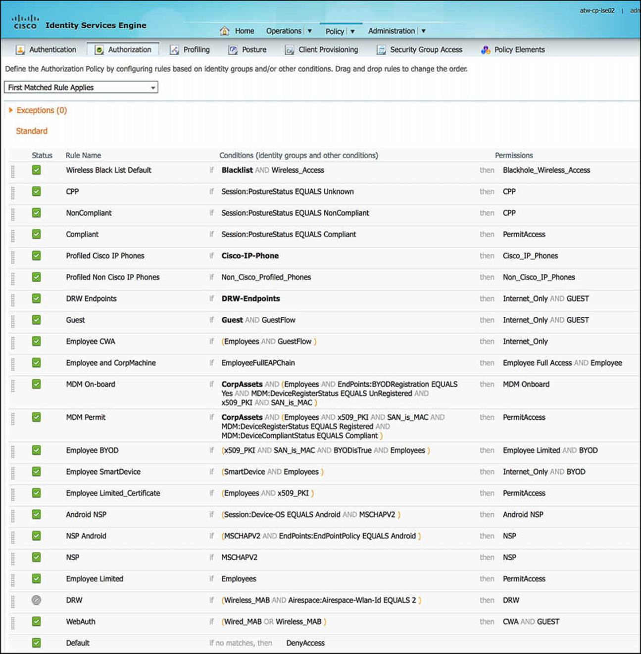
Figure 14-26 Proper ordering of authorization rules for MAB successes and failures.
As we look further down the authorization policy, we will see that there is an explicit mention of Wireless_MAB and Wired_MAB in the authorization rule WebAuth, just before the Default rule. Looking at this rule, the conditions column contains Wired_MAB OR Wireless_MAB (please notice the OR keyword). This rule will take effect only if
![]() All other rules before it don’t match.
All other rules before it don’t match.
![]() The endpoint is using MAB to authenticate to the network (either wired or wireless).
The endpoint is using MAB to authenticate to the network (either wired or wireless).
Again, the Wired_MAB and Wireless_MAB conditions are authentication conditions that are configured as
![]() Wired_MAB = Radius:Service-Type = Call Check AND Radius:NAS-Port-Type = Ethernet
Wired_MAB = Radius:Service-Type = Call Check AND Radius:NAS-Port-Type = Ethernet
![]() Wireless_MAB = Radius:Service-Type = Call Check AND Radius:NAS-Port-Type = Wireless—IEEE 802.11
Wireless_MAB = Radius:Service-Type = Call Check AND Radius:NAS-Port-Type = Wireless—IEEE 802.11
If either of these conditions is met, the endpoint will be granted the level of access contained in the authorization profile CWA and SGA Policy GUEST. This will provide an initial authorization that provides basic network access and allows the guest user an opportunity to authenticate via a web-based interface. We discuss these authorization profiles and how this web authentication process happens shortly.
A second option besides the one we just mentioned is to use a specific RADIUS condition within ISE designed for this process flow—Network Access:UseCase EQUALS Host Lookup. This rule implies that a MAB process is underway (that is, a host lookup has happened) and has failed to hit all previous and explicit MAB authorization rules within the authorization policy. It accomplishes exactly the same task as our original, configured rule. Depending on your company’s security policy and required use cases, your policy and Guest Services approach can take a slightly different approach yet end up with the same result. ISE is extremely flexible and can accommodate several scenarios.
Usually, the Guest Services’ failed MAB rule is placed just above the Default authorization rule. As mentioned previously, you can design your rule set, authentication and-authorization both, to allow a user to continue connecting to the network following a failed authentication and then eventually elect the Default authorization rule. This would be just one more way to accommodate Guest Services access. Again, ISE is extremely flexible and you can use several approaches to accomplish the same goal.

Please use extreme caution when having a final Default rule that does not provide a RADIUS ACCESS_REJECT response because this could provide a nefarious user access to your network that you might not completely intend.
Now that the user has been authorized to access the network, let’s take a look at what this authorization means to the endpoint and end user. As an endpoint fails to match a MAB endpoint identity group and hits the WebAuth authorization rule, the endpoint—and therefore the user—will be assigned the authorization profile CWA and SGA Security Group GUEST. Let’s first take a look at the CWA authorization profile (Figure 14-27 through Figure 14-30).
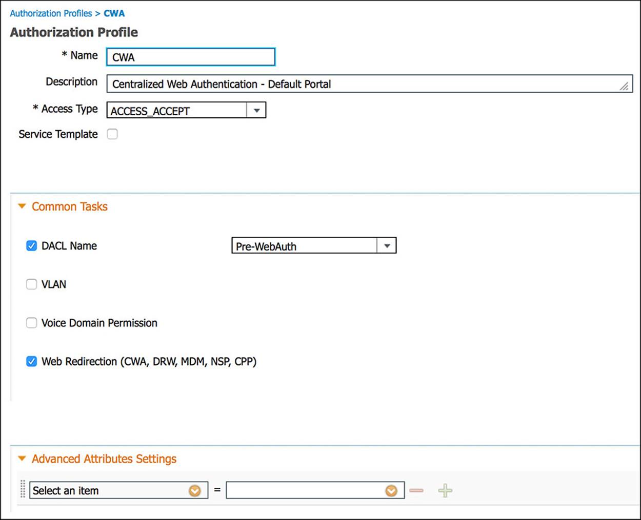
Figure 14-27 CWA authorization profile, part 1.
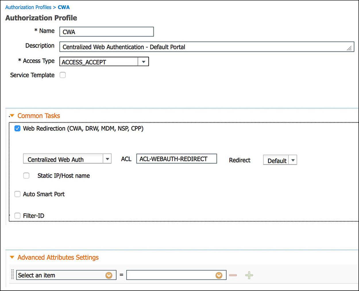
Figure 14-28 CWA authorization profile, part 2.
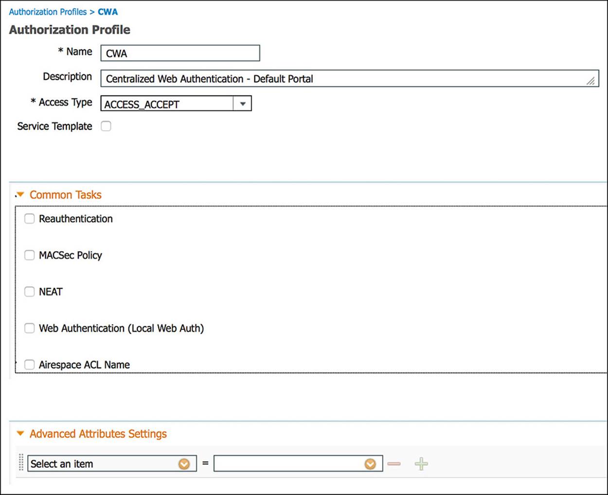
Figure 14-29 CWA authorization profile, part 3.
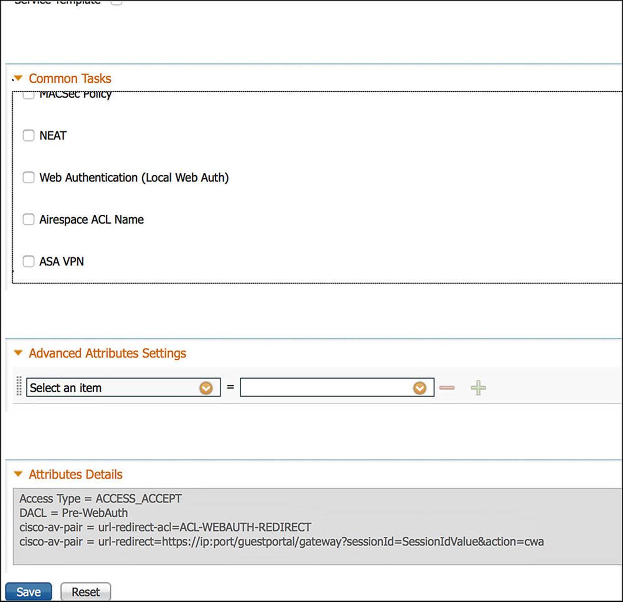
Figure 14-30 CWA authorization profile, part 4.
Looking at Figure 14-27, you will first notice the name and description followed by an access type of ACCESS_ACCEPT. This ACCESS_ACCEPT implies that some level of access will be provided to the endpoint. This access can be extremely open or extremely restrictive, but the result is access nonetheless.
Further down in Figure 14-27 is the Common Tasks section. This section, as you learned in earlier chapters, helps simplify the configuration for those security elements that are used often by network administrators. For the CWA authorization profile, we will leverage several of these common tasks.
The first common task we will leverage is the DACL name (see Figure 14-27). DACL, an acronym for Downloadable Access Control List, is an access list, most often used in a wired scenario, that is pushed from ISE down to the NAD. The DACL that we will push to the NAD for the CWA rule is named Pre-WebAuth. This ACL is defined on ISE via the Policy > Policy Elements > Results > Authorization > Downloadable ACLs (see Figure 14-31).
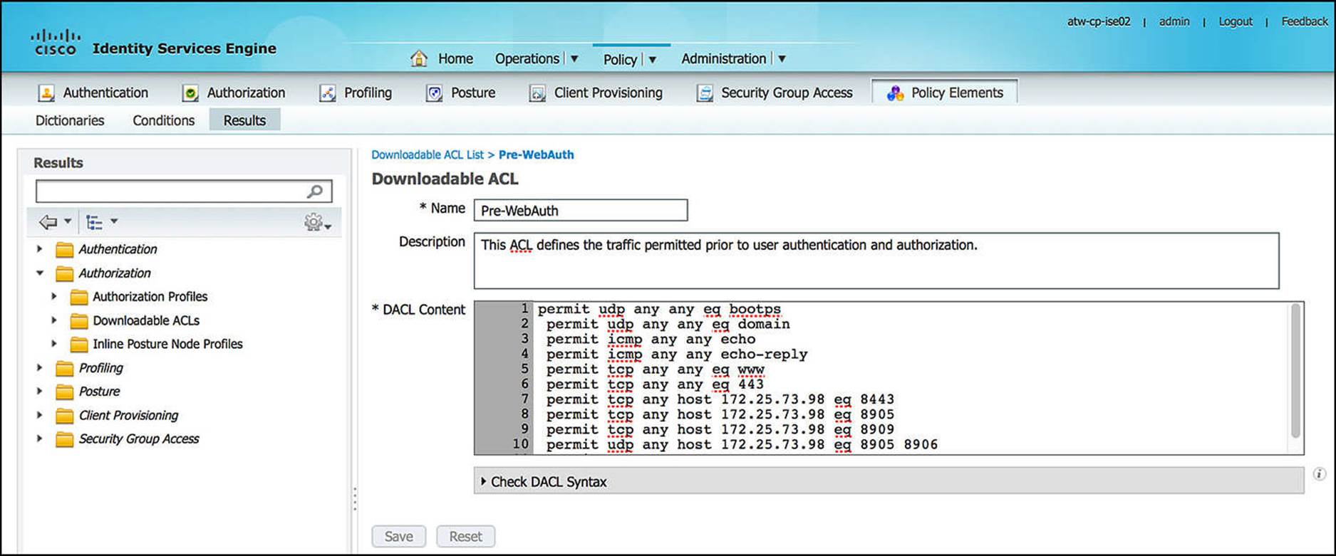
Figure 14-31 Pre-WebAuth DACL.
As the contents of this ACL continue beyond the bottom of the textbox on Figure 14-31, the complete contents of this Pre-WebAuth DACL, commented for your understanding, are shown in Example 14-1:
Example 14-1 Pre-WebAuth DACL
! Traffic to a DHCP server
permit udp any any eq bootps
! Traffic to a DNS server
permit udp any any eq domain
! Ping traffic and response for diagnostics purposes
permit icmp any any echo
permit icmp any any echo-reply
! Traffic to HTTP websites—must be permitted before being redirected
permit tcp any any eq www
! Traffic to HTTPS websites—must be permitted before being redirected
permit tcp any any eq 443
! Traffic to ISE portals, posturing, posture remediation, and provisioning
! functions
permit tcp any host 172.25.73.98 eq 8443
permit tcp any host 172.25.73.98 eq 8905
permit tcp any host 172.25.73.98 eq 8909
permit udp any host 172.25.73.98 eq 8905 8906
permit udp any host 172.25.73.98 eq 8909
As the user is assigned the CWA authorization profile, this Pre-WebAuth ACL is pushed to the NAD, line by line, in its entirety, using the RADIUS protocol. This ACL will be instantiated on the NAD and will restrict to which devices the endpoint will have access.
The next common task we’ll leverage for the CWA authorization profile is Web Redirection (see Figure 14-28). Web Redirection can serve a number of purposes depending on which parameters are selected. In the case of Guest Services, we will be leveraging the Centralized Web Auth web redirection configuration. This is the reason we chose to name this authorization profile CWA—it contains a Centralized Web Authentication portal component. As the name suggests, this will redirect the user to a web portal that is hosted on ISE to authenticate the user.
One of the parameters required by the Centralized Web Auth function is an ACL via the ACL drop-down. The ACL we will choose here is a named ACL versus the downloadable ACL we just mentioned. A named ACL is statically defined on the NAD; ISE will simply invoke the ACL’s use by reference alone. In this case, the ACL named ACL-WEBAUTH-REDIRECT is defined on the NAD and referenced as part of the Web Redirection configuration. The function of this ACL is to define what traffic will trigger the redirect. If traffic generated by the endpoint matches this ACL, the endpoint will be sent to the web portal that is selected—in this case, the Centralized Web Auth portal. The contents of this ACL were defined in Chapter 12.
The final parameter that we can configure as part of the Centralized Web Auth web redirection is the Redirect parameter. This Redirect drop-down enables the network administrator to select either the default Centralized Web Authentication portal or a custom portal, allowing the network administrator to customize the user experience as well as invoke specific portal rules based on the company’s security policy. By default, the Default redirect is chosen—the default Centralized Web Authentication portal. However, if you have configured a custom portal, modifying any of the security parameters or portal behavior, you can redirect the end user to this custom portal by selecting the custom portal from the drop-down.
The rest of the common tasks are left as their defaults (unselected) for the CWA authorization profile (see Figure 14-29 and Figure 14-30). You can see the RADIUS Attribute-Value pairs for the totality of the configured parameters for the CWA authorization profile by looking at the box labeled Attributes Details in Figure 14-30. These attributes are sent to the NAD whenever the CWA authorization is hit.
We’ll now take a look at the SGA Security Group GUEST. Looking at Figure 14-32, you will see that the GUEST SGA Security Group is assigned the Security Group Tag (SGT) of 8.
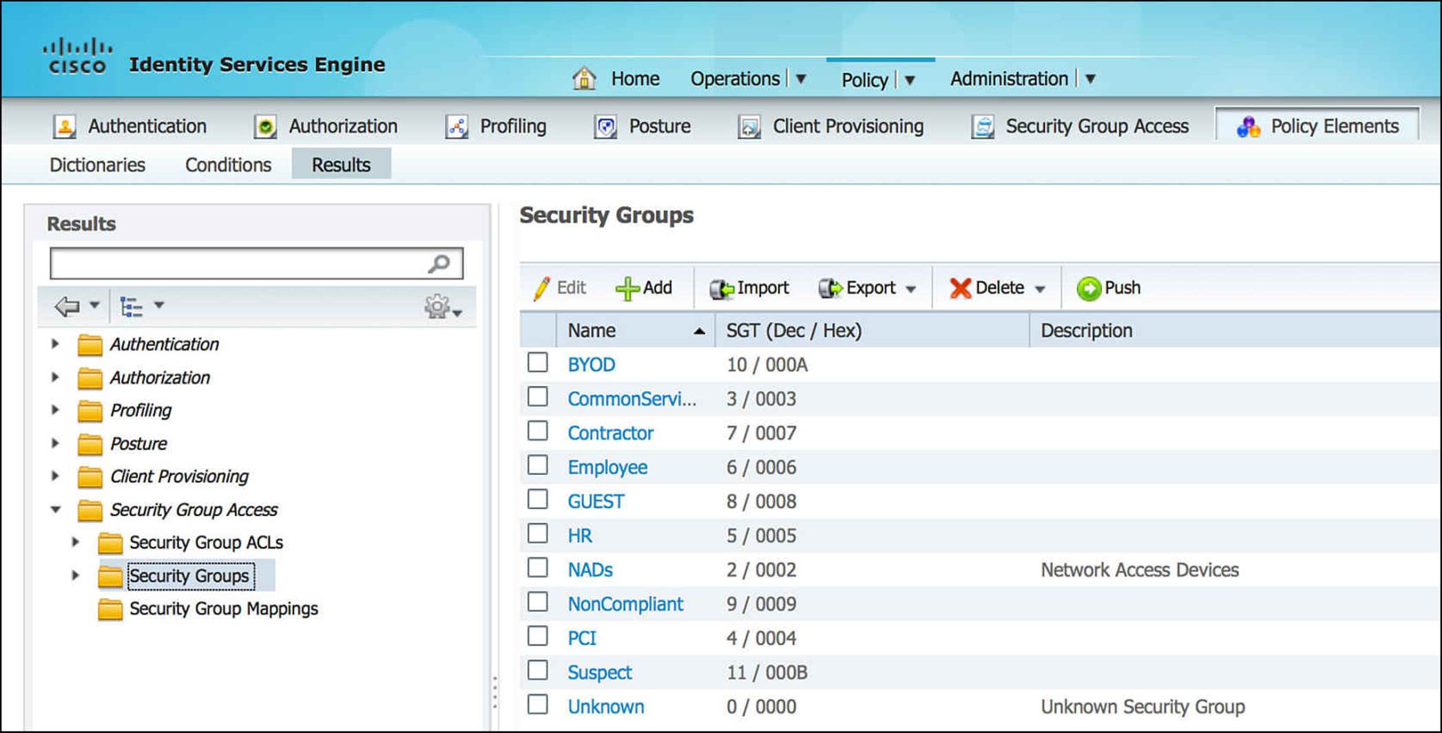
Figure 14-32 SGA security group.
With the SGT assignment of the GUEST policy, we really don’t have the whole picture. We need to see the Security Group Access Egress Policy Matrix (see Figure 14-33). In this matrix, you can see that other SGTs are defined for other devices on the network. By looking at the SGT assigned to GUEST (that is, 8) on the left side of this table—the Source Tag—you can determine which destination tag(s) is a viable destination for the GUEST SGT. In Figure 14-33, you can see that SGT 8 is explicitly denied access to Contractors (SGT 7), Employees (SGT 6), Guests (SGT 8), and HR (SGT 5). Otherwise, by explicit configuration or by the default rule at the bottom, the GUEST SGT is allowed access to all other resources on the network.
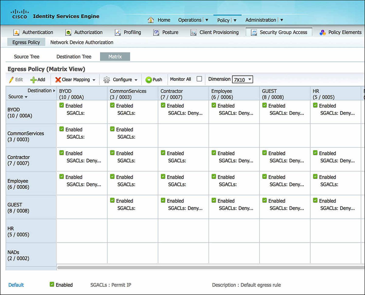
Figure 14-33 SGA egress policy matrix.
Now, the guest user’s authorization on the NAD contains a downloadable ACL that limits what the user is allowed to access and a redirect URL (with corresponding redirect ACL). As the user attempts to access a network resource—any resource that matches the ACL-WEBAUTH-REDIRECT ACL—the NAD will redirect the unauthenticated user to the ISE for authentication.
Via the WebAuth portal, the client will be asked to provide his sponsor-generated username and password. If the guest user provides valid credentials, ISE will trigger a CoA to the NAD as we discussed at the beginning of this chapter, forcing a reauthorization. The user will again be processed through the authorization rule set.
Everything about the second authorization process will behave exactly as the first authorization process, with one exception—a flag will be set within ISE that says that the initial WebAuth was successful. This prevents ISE from getting into an endless loop for authentication and authorization whereby the client hits the catch-all MAB rule each time. To achieve a distinct experience during the reauthorization, we’ve created an Authorization rule named Guest.
This Guest rule will match if two conditions are met—the username is part of the user identity group called Guests and the RADIUS session is using GuestFlow. The user identity group Guests is the repository where the created guest users’ credentials will be stored for use. GuestFlow is a simple condition whereby Network Access:UseCase Equals Guest Flow, meaning the guest user had already successfully authenticated to the WebAuth portal. If the initial WebAuth process was successful, ISE will link the successful authentication with the RADIUS session, making the Network Access:UseCase Equals Guest Flow equal TRUE. Because both conditions are true, the endpoint, and therefore the user, will be assigned the authorization profile of Internet_Only and SGA policy of GUEST. We’ve already discussed the SGA policy of GUEST, whereby the endpoint is assigned SGT 8 and explicitly denied access to Contractors (SGT 7), Employees (SGT 6), Guests (SGT 8), and HR (SGT 5). Let’s briefly discuss the Internet_Only authorization profile.
Looking at the Internet_Only profile (see Figure 14-34 through Figure 14-36), as was the case with the CWA authorization profile, the Access Type is ACCESS_ACCEPT. Again, ACCESS_ACCEPT simply means that some level of access will be granted to the endpoint, however restrictive or permissive. You will also notice that the DACL Name is also selected as a common task (see Figure 14-34). However, the value of this DACL name is indeed different from the CWA profile. In this case, the DACL is named Internet_Only and is configured as shown in Figure 14-37 for wired deployments.
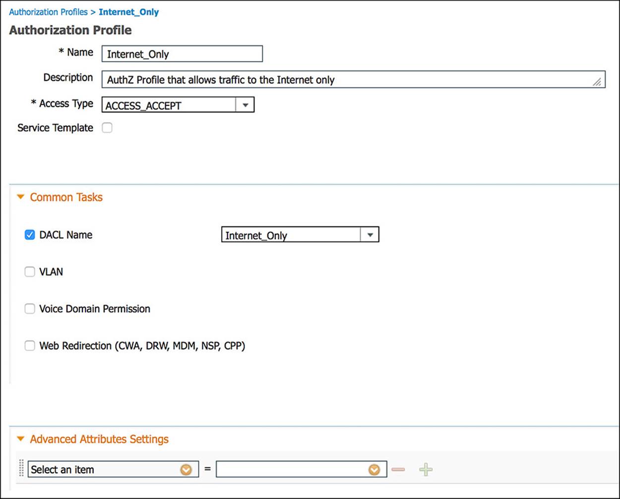
Figure 14-34 Internet_Only authorization profile, part 1.
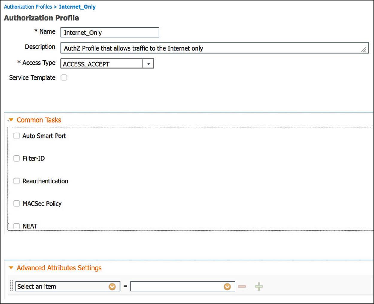
Figure 14-35 Internet_Only authorization profile, part 2.
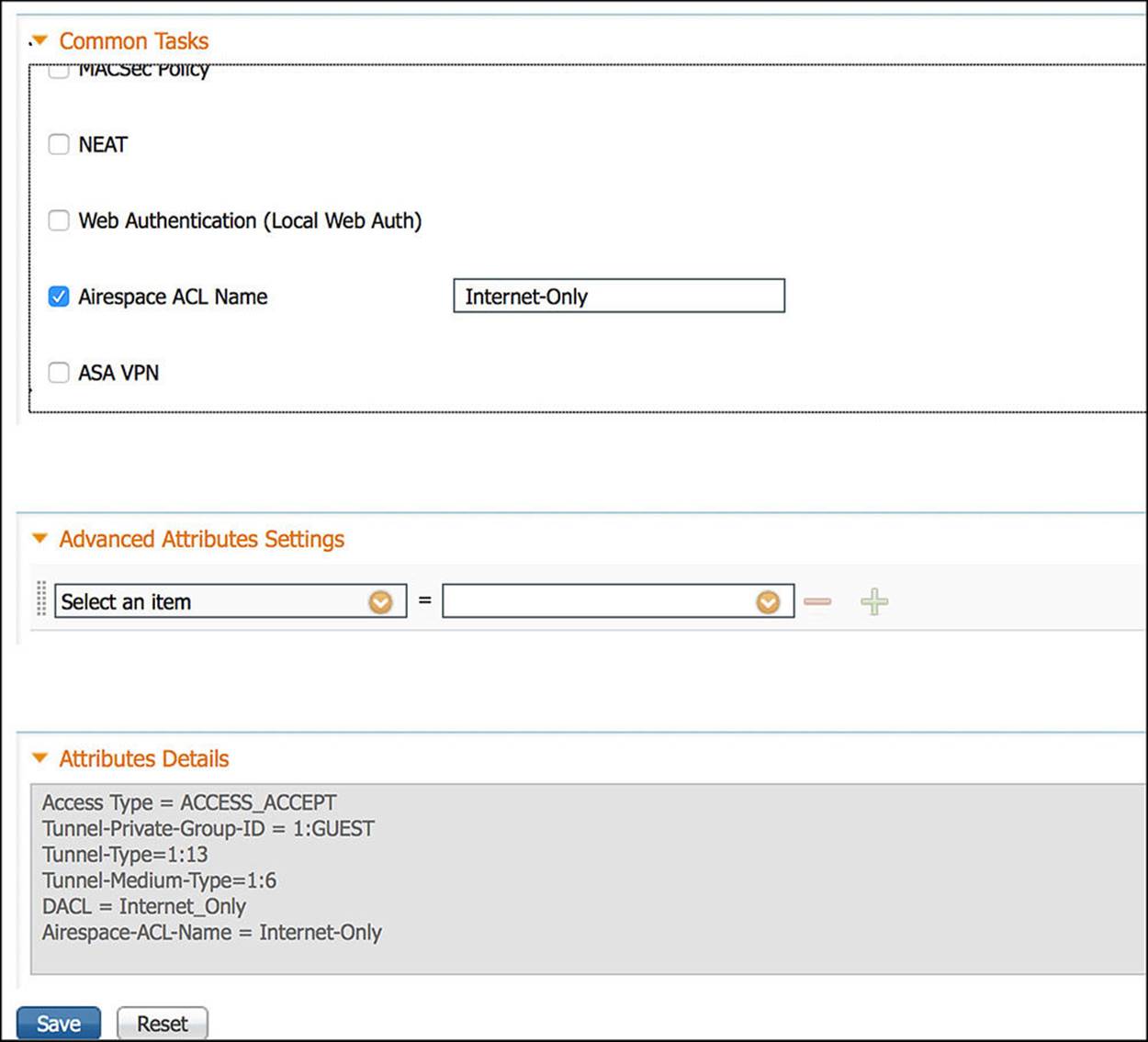
Figure 14-36 Internet_Only authorization profile, part 3.
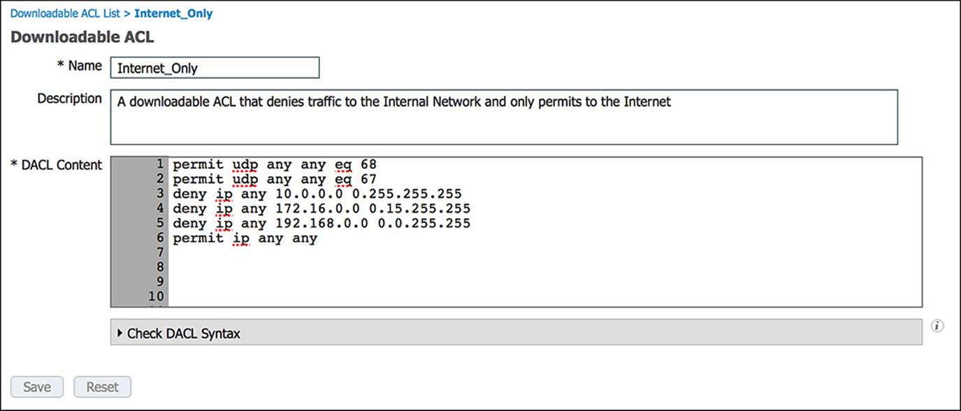
Figure 14-37 Internet_Only DACL.
The entries in the Internet_Only ACL is commented in Example 14-2 for your understanding:
Example 14-2 Internet_Only ACL
! Traffic from DHCP client
permit udp any any eq 68
! Traffic to a DHCP server
permit udp any any eq 67
! Deny all traffic to RFC1918 private/internal IP ranges
deny ip any 10.0.0.0 0.255.255.255
deny ip any 172.16.0.0 0.15.255.255
deny ip any 192.168.0.0 0.0.255.255
! Allow all other traffic—i.e. Internet-bound traffic
permit ip any any
The other common task we’ll leverage for the Internet_Only authorization profile is Airespace ACL Name. Airespace ACL Name is a RADIUS Attribute-Value Pair to send a named ACL to Cisco’s wireless access points (APs), usually via a Wireless LAN Controller (WLC). Many of Cisco’s APs do not allow more than 64 ACLs and no more than 64 access control entries per list. This restriction can limit the number of ACLs that can be used in the wireless domain. To support this approach while minimizing overhead, ISE leverages the named ACL approach, whereby the administrator will define ACLs explicitly on the WLC that is controlling the APs. ISE will then send a RADIUS Attribute-Value pair to the NAD instructing which ACL to associate with the endpoint/user. At that point, the endpoint’s access will be appropriately limited depending on the named ACL that was referenced in the RADIUS exchange.
The Internet-Only named ACL for the WLC is shown in Figure 14-38.
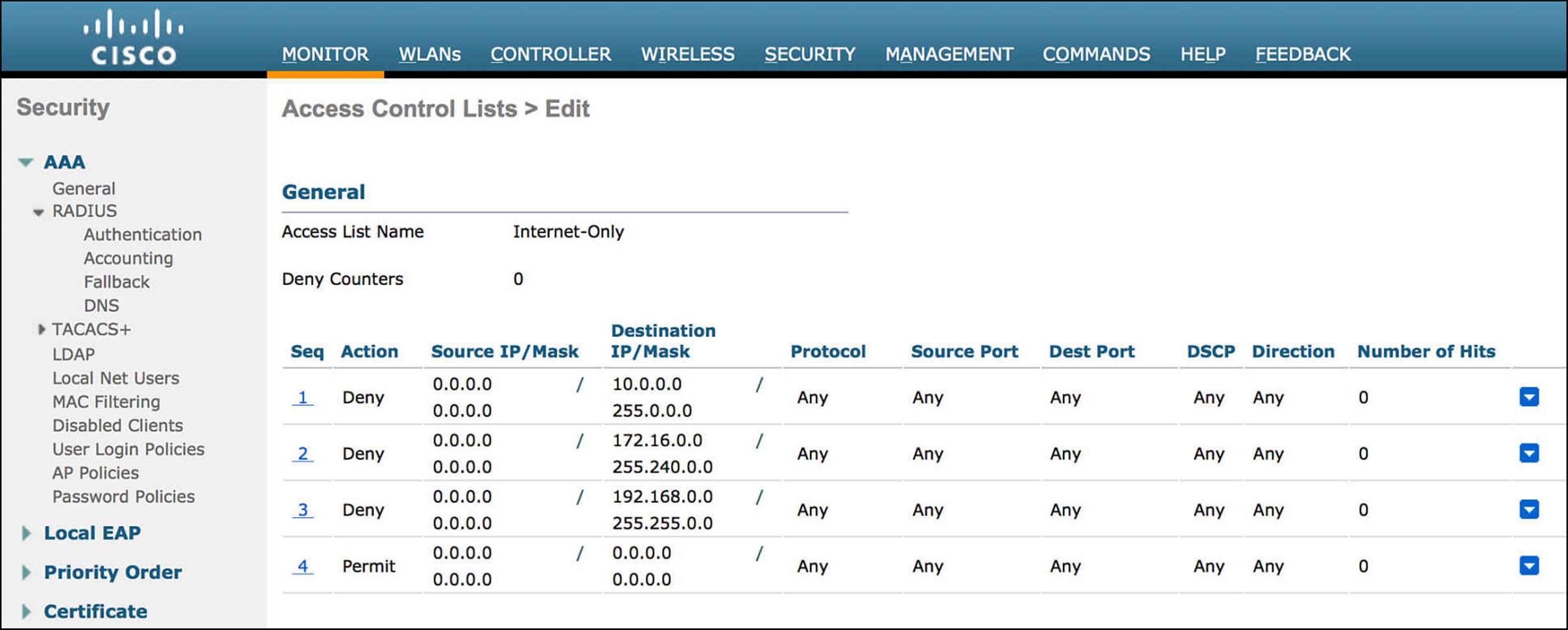
Figure 14-38 Internet-Only named ACL.
As you can see in this section, ISE can be extremely flexible in handling a number of scenarios for guest users—for both authentication as well as authorization. By breaking the overall process flow down into smaller, more easily consumable pieces, we were able to construct a very effective and quite restrictive guest access policy. Of course, depending on your own security policy, the level of access granted at each step along the way, as well as the conditions that trigger the access, might be completely different.
Provisioning Guest Accounts from a Sponsor Portal
The sponsor portal of ISE is mostly self-explanatory (see Figure 14-39). As you browse to the ISE sponsor portal (the default URL is https://<PSN_IP_OR_FQDN>:8443/sponsorportal), you will see that there are three key options—create a single account, create random accounts, and import accounts. Depending on which sponsor group you are a member of, you might or might not be able to use all three of these options. We’ll now discuss each of these options in more detail.
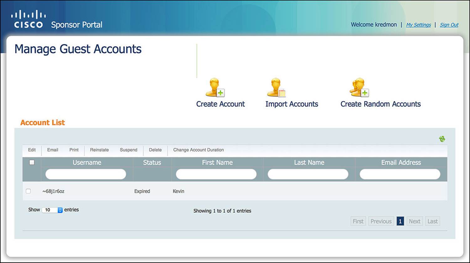
Figure 14-39 Sponsor portal.
Individual
To create an individual user account, such as a single guest user who is visiting the office for the day, click the man icon labeled Create Account. As you click this link, you will be presented with several options, as shown in Figure 14-40. Some of these fields will be limited to certain values, commensurate with your sponsor group.
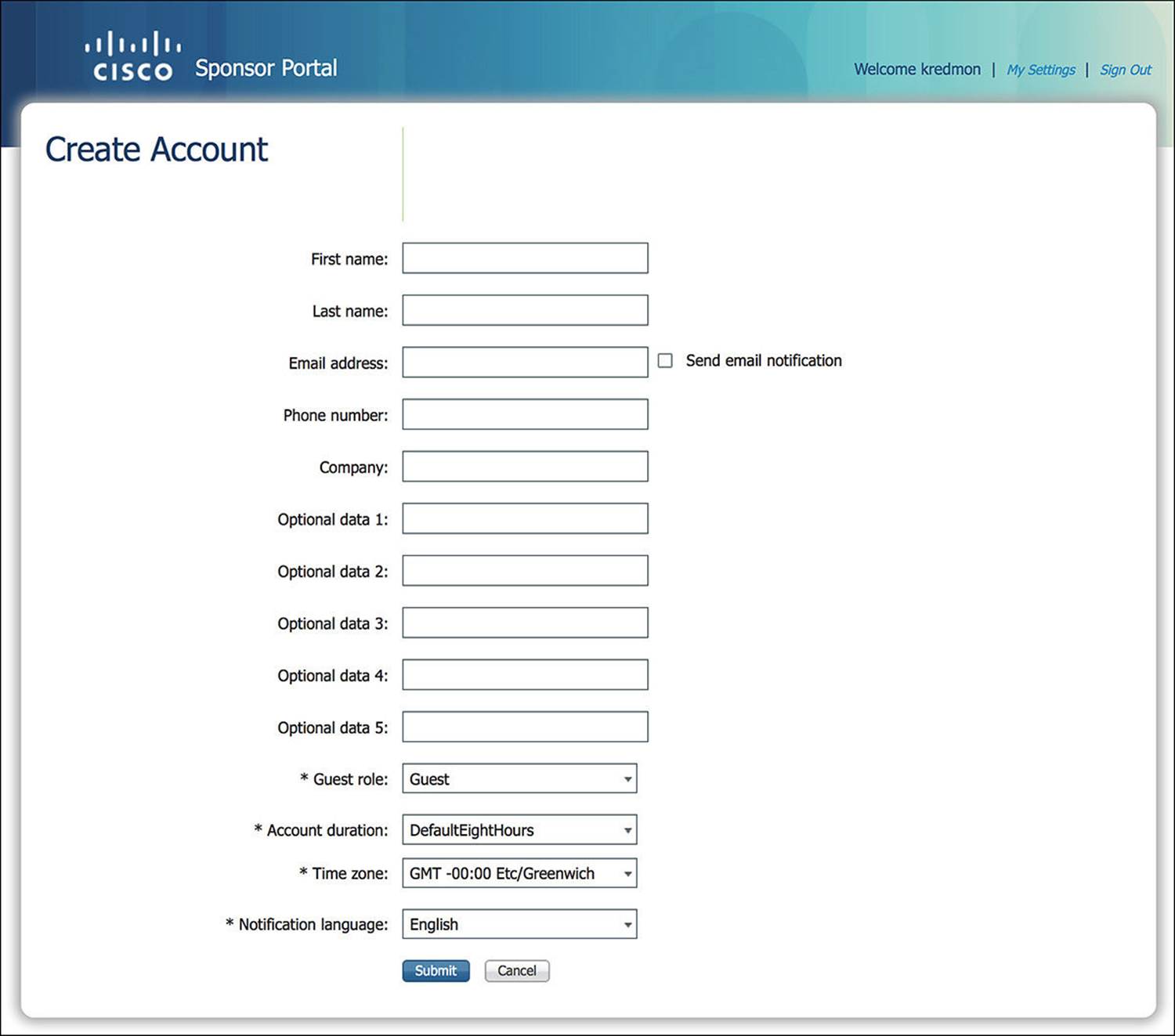
Figure 14-40 Sponsor portal individual account creation.

Depending on your security policy, some of these options might be required while others might be optional. You can configure which options are required by browsing to Administration > Web Portal Management > Settings > Guest > Details Policy. If you want to modify the Optional Data fields to be something more meaningful, you can do so by going to the Administration > Web Portal Management > Settings > Sponsor > Language Template. Select the appropriate language that should be modified. After selecting the appropriate language, you can now choose which sponsor portal page needs to be modified (such as Configure Create Single Guest Account).
Optional versus required fields are global across all guest portals.
Random
If you are hosting a conference with a large number of people attending or hosting a tour of your corporation, it might not always be possible to know the names of everyone attending well ahead of time. Furthermore, you may simply not want to give the guest users easily guessable usernames. Whichever the case, ISE provides the ability to create random user accounts. To create random user accounts, click the man icon labeled Create Random Accounts.
After you click this link, you be asked to input the number of user accounts that will be required as well as a username prefix, which is optional (see Figure 14-41). This prefix will be prepended to the username of each guest user account that will be created. Again, some of the fields will be limited to certain values, commensurate with your sponsor group.
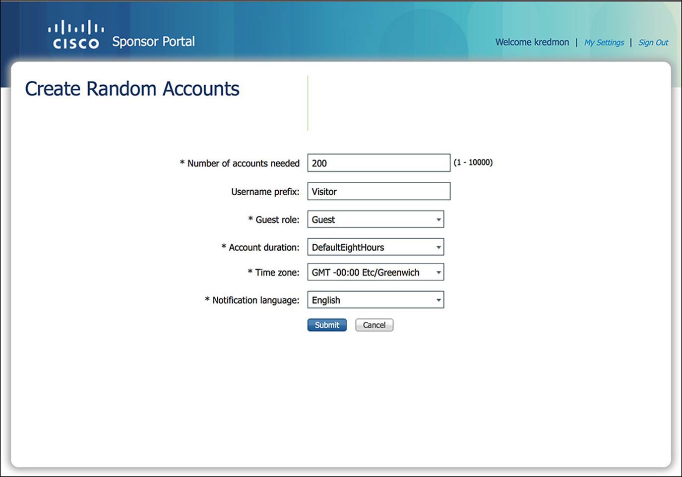
Figure 14-41 Sponsor portal random account creation.
Import
A third option to create guest user accounts is by importing a CSV that contains the requested data for each guest user account. To create guest user accounts using the import function, click the man icon labeled Import Accounts.
As you click the link, you can select the file that contains the user accounts (see Figure 14-42). If you are not confident as to the format of the file, you can download a template by clicking the Download Template button. This template will provide many of the same fields as requested in the Individual Account creation. Once you have populated the file with the required fields, select the file by clicking the Browse button; then click Upload. As the file uploads, you will see a list within the sponsor portal of all user accounts that were detected in the file. You are not done yet. If all the usernames look correct and were properly parsed, click Submit. After you click Submit, you will see a list of all usernames from the file and the created passwords.
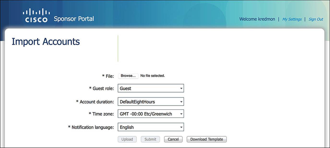
Figure 14-42 Sponsor portal import account creation.
Verifying Guest Access on the WLC/Switch
When a guest user connects to the network via Guest Services, several RADIUS exchanges must happen between the NAD (WLC or switch) and ISE for the guest’s network access to be successful. We’ll review the steps to verify that the guest access is going well from all angles—from the standpoint of the NAD (WLC and switch) and from ISE.
WLC
As a guest user attempts to connect to the network wirelessly, the endpoint must go through the following steps:
1. The endpoint must be connected to the correct SSID—Guest Services, we have determined that the endpoint must be authenticating to the network using MAB. On the WLC, you must enable MAC filtering to trigger a MAB authentication on the SSID in question. In this case, the SSID that you’ll be associating to is CP-Guest, which does indeed have MAC filtering enabled under the column Security Policies. You can view a summary of the SSIDs/WLANs present on a WLC by clicking the WLANs link across the top bar (see Figure 14-43).

Figure 14-43 Wireless LAN controller SSIDs/WLANs.
2. The initial authorization policy pushed to the endpoint must be CWA and SGA policy of GUEST—As the endpoint first associates to the SSID, ISE will determine that the client is using MAB based on the RADIUS Service-Type sent by the WLC to ISE. However, as we discussed earlier, the MAC address is not present in the endpoint identity store. This will enable the endpoint to hit the WebAuth rule because WebAuth is the catchall MAB rule when the endpoint is not in the endpoint database. The resulting authorization profile should be CWA and an SGA Policy of GUEST.
On ISE, you can easily see that we have hit the WebAuth rule, which we’ll discuss shortly. However, on the WLC, it is not as straightforward. On the WLC, to ensure that the client has hit the correct rule, we must look at the status of the endpoint on the WLC (see Figure 14-44). To look at the status of the endpoint on the WLC, you must click Monitor > Clients and then click the MAC address of the client in question.
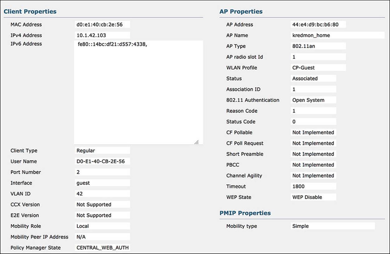
Figure 14-44 WLC endpoint status – WebAuth.
ISE should push the following information to the WLC on behalf of the endpoint when the CWA policy is hit:
![]() MAC Address—Confirm that the MAC address matches the endpoint in question.
MAC Address—Confirm that the MAC address matches the endpoint in question.
![]() WLAN Profile—Although this isn’t pushed to the WLC by ISE, it is still a good idea to confirm that the correct SSID is showing. In this case, the SSID should be CP-Guest, which it is.
WLAN Profile—Although this isn’t pushed to the WLC by ISE, it is still a good idea to confirm that the correct SSID is showing. In this case, the SSID should be CP-Guest, which it is.
![]() Policy Manager State—The Policy Manager state is an indication of the wireless connection status. In the case of CWA, the Policy Manager state should be CENTRAL_WEB_AUTH. This corresponds to the Centralized Web Auth web redirection we enabled on ISE CWA policy.
Policy Manager State—The Policy Manager state is an indication of the wireless connection status. In the case of CWA, the Policy Manager state should be CENTRAL_WEB_AUTH. This corresponds to the Centralized Web Auth web redirection we enabled on ISE CWA policy.
![]() AAA Override ACL Name—The AAA override ACL name is the ACL that is used for web redirection. This named ACL was defined as ACL-WEBAUTH-REDIRECT on the CWA policy on ISE.
AAA Override ACL Name—The AAA override ACL name is the ACL that is used for web redirection. This named ACL was defined as ACL-WEBAUTH-REDIRECT on the CWA policy on ISE.
![]() Redirect URL—The redirect URL is the URL for the WebAuth portal for the guest user. As the guest user attempts to browse to a website, this redirect will send the user to ISE to authenticate. This URL will point to one of the ISE PSNs.
Redirect URL—The redirect URL is the URL for the WebAuth portal for the guest user. As the guest user attempts to browse to a website, this redirect will send the user to ISE to authenticate. This URL will point to one of the ISE PSNs.
![]() CTS Security Group Tag—The SGA policy of GUEST assigns the SGT of 8 to the endpoint. You can see that value here under the variable CTS security group tag.
CTS Security Group Tag—The SGA policy of GUEST assigns the SGT of 8 to the endpoint. You can see that value here under the variable CTS security group tag.
3. The final authorization policy pushed to the endpoint must be Internet_Only and an SGA policy of GUEST—As the guest user authenticates and the NAD receives a CoA from ISE, the endpoint is sent back through the authorization process. Becuase a successful authentication occurs, the endpoint should now hit the Internet_Only authorization profile. This profile is a little less involved than the CWA policy.
ISE should push the following information to the WLC when the Internet_Only profile is hit (see Figure 14-45):
![]() MAC Address—Again, confirm that the MAC address matches the endpoint in question.
MAC Address—Again, confirm that the MAC address matches the endpoint in question.
![]() WLAN Profile—Although this isn’t pushed to the WLC by ISE, it is still a good idea to confirm that the correct SSID is showing. In this case, the SSID should still be CP-Guest, which it is.
WLAN Profile—Although this isn’t pushed to the WLC by ISE, it is still a good idea to confirm that the correct SSID is showing. In this case, the SSID should still be CP-Guest, which it is.
![]() Policy Manager State—In the case of Internet_Only, the Policy Manager state should be RUN. This is the final connection state for the endpoint.
Policy Manager State—In the case of Internet_Only, the Policy Manager state should be RUN. This is the final connection state for the endpoint.
![]() AAA Override ACL Name—In the Internet_Only profile, there should NOT be a AAA override ACL name.
AAA Override ACL Name—In the Internet_Only profile, there should NOT be a AAA override ACL name.
![]() Redirect URL—Because the guest user has authenticated, the endpoint should no longer need to be redirected. For this reason, the redirect URL should be blank.
Redirect URL—Because the guest user has authenticated, the endpoint should no longer need to be redirected. For this reason, the redirect URL should be blank.
![]() IPv4 ACL Name—In the case of (Wireless) CWA, there was no IPv4 ACL name. The AAA override ACL name was doing all necessary filtering of the traffic. Now that ISE has authenticated the guest user and, therefore, the endpoint, ISE will now push the Airespace ACL of Internet-Only to the WLC. As we discussed earlier in the chapter, an Airespace ACL is also a named ACL that is predefined on the WLC.
IPv4 ACL Name—In the case of (Wireless) CWA, there was no IPv4 ACL name. The AAA override ACL name was doing all necessary filtering of the traffic. Now that ISE has authenticated the guest user and, therefore, the endpoint, ISE will now push the Airespace ACL of Internet-Only to the WLC. As we discussed earlier in the chapter, an Airespace ACL is also a named ACL that is predefined on the WLC.
![]() CTS Security Group Tag—The SGA Policy of GUEST is exactly the same as the CWA policy. Looking at this field, you will again see that it is 8.
CTS Security Group Tag—The SGA Policy of GUEST is exactly the same as the CWA policy. Looking at this field, you will again see that it is 8.
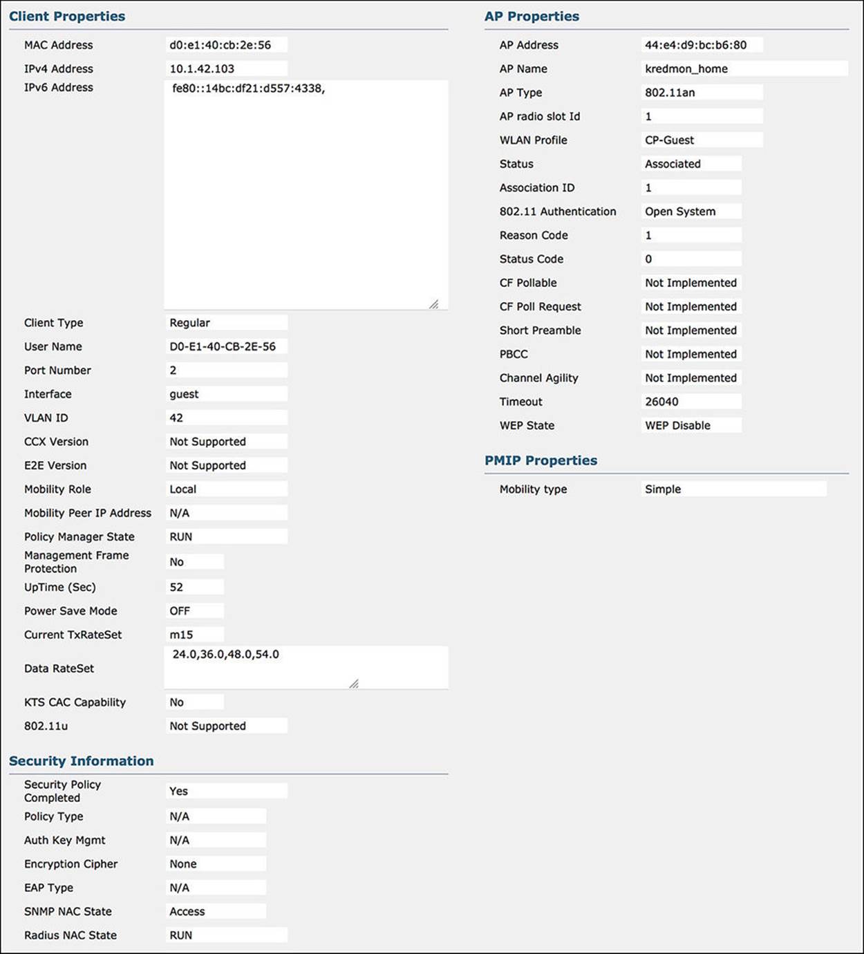
Figure 14-45 WLC Endpoint Status—Internet_Only.
Now that we have validated the connection from the standpoint of the WLC, we can take a look at ISE, highlighting the communications that are sent between the WLC and ISE and the return traffic. When we look at the ISE authentication details for the initial WebAuth authorization, and the final Internet_Only authorization, we will need to ensure that all authorization conditions are met from the WLC and that the ISE pushes the correct information back to the WLC in both cases.
4. ISE gets the initial authentication request and sends the WLC the CWA authorization profile and SGA policy GUEST—When the endpoint first joins the WLC, the WLC will send a MAB request to ISE. For the endpoint to hit the WebAuth policy, the WLC must meet the conditions of Wireless_MAB (or Wired_MAB, but we know that this endpoint is wireless). This initial authentication request should result in the following communications:
![]() From WLC to ISE—Looking at the authentication details for the endpoint in question (the magnifying glass in the Details column of the Authentication Live Log), there are a number of sections in the output. For the communication from the NAD, you will need to look at the Overview and Authentication Details section of the output (see Figure 14-46).
From WLC to ISE—Looking at the authentication details for the endpoint in question (the magnifying glass in the Details column of the Authentication Live Log), there are a number of sections in the output. For the communication from the NAD, you will need to look at the Overview and Authentication Details section of the output (see Figure 14-46).
![]() Authorization Profile—The Overview shows the condensed version of the authorization output. Looking at the authorization profile, you will see CWA and GUEST. These are the authorization profile and SGA policy you should be seeing.
Authorization Profile—The Overview shows the condensed version of the authorization output. Looking at the authorization profile, you will see CWA and GUEST. These are the authorization profile and SGA policy you should be seeing.
![]() AuthorizationPolicyMatchedRule—This variable tells us the name of the authorization rule we hit. In the case of a guest authenticating to the network, the rule we should hit is indeed WebAuth.
AuthorizationPolicyMatchedRule—This variable tells us the name of the authorization rule we hit. In the case of a guest authenticating to the network, the rule we should hit is indeed WebAuth.
![]() Endpoint ID—When looking at the authentication details for a particular endpoint, ensure that you are looking at the MAC address of the correct endpoint.
Endpoint ID—When looking at the authentication details for a particular endpoint, ensure that you are looking at the MAC address of the correct endpoint.
![]() Authentication Method—The Authentication method as seen on the authentication details should be MAB.
Authentication Method—The Authentication method as seen on the authentication details should be MAB.
![]() Service Type—The service type for a MAB connection from a Cisco WLC should be Call Check.
Service Type—The service type for a MAB connection from a Cisco WLC should be Call Check.
![]() NAS Port Type—The NAS port type for a wireless connection should be Wireless—IEEE 802.11.
NAS Port Type—The NAS port type for a wireless connection should be Wireless—IEEE 802.11.
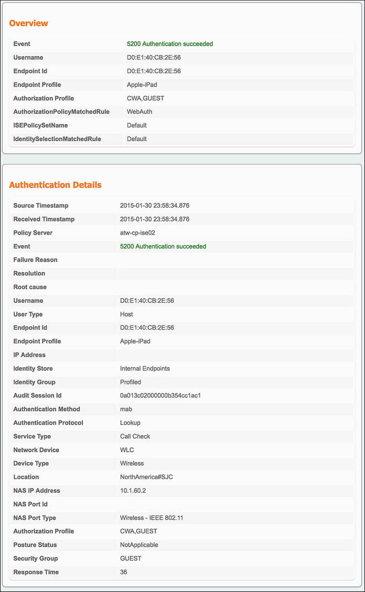
Figure 14-46 ISE Authentication Details Live Log—Wireless WebAuth.
Because Wireless_MAB is defined by a service type of Call Check and a NAS port type of Wireless—IEEE 802.11, the conditions for the CWA authorization profile and SGA policy of GUEST have been met. ISE must now send the resulting authorization profile back to the WLC. The information in this authorization profile is provided in the Result section of the authentication details. Looking at this output (shown in Figure 14-47), we see:
![]() From ISE to WLC—The output in the Result section of the authentication live log is
From ISE to WLC—The output in the Result section of the authentication live log is
![]() Redirect URL—The redirect URL is contained within one of the cisco-av-pair outputs, specifically the one that begins with url-redirect=. As you look at the rest of the URL, you will notice that there is a parameter called action=cwa. As the endpoint is redirected to that URL, ISE recognizes this parameter as a CWA call and provides the endpoint the correct webpage.
Redirect URL—The redirect URL is contained within one of the cisco-av-pair outputs, specifically the one that begins with url-redirect=. As you look at the rest of the URL, you will notice that there is a parameter called action=cwa. As the endpoint is redirected to that URL, ISE recognizes this parameter as a CWA call and provides the endpoint the correct webpage.
![]() Redirect ACL—The redirect ACL is also contained within one of the cisco-av-pair outputs in the Result section. In this case, the cisco-av-pair will begin with url-redirect-acl= (notice the acl at the end), specifically mentioning the ACL-WEBAUTH-REDIRECT ACL.
Redirect ACL—The redirect ACL is also contained within one of the cisco-av-pair outputs in the Result section. In this case, the cisco-av-pair will begin with url-redirect-acl= (notice the acl at the end), specifically mentioning the ACL-WEBAUTH-REDIRECT ACL.
![]() Security Group Tag—The SGT that was assigned to the endpoint can also be found in the Result section of the authentication details. Again, this value will be embedded in a cisco-av-pair—namely the AV pair of cts:security-group-tag=0008-0.
Security Group Tag—The SGT that was assigned to the endpoint can also be found in the Result section of the authentication details. Again, this value will be embedded in a cisco-av-pair—namely the AV pair of cts:security-group-tag=0008-0.
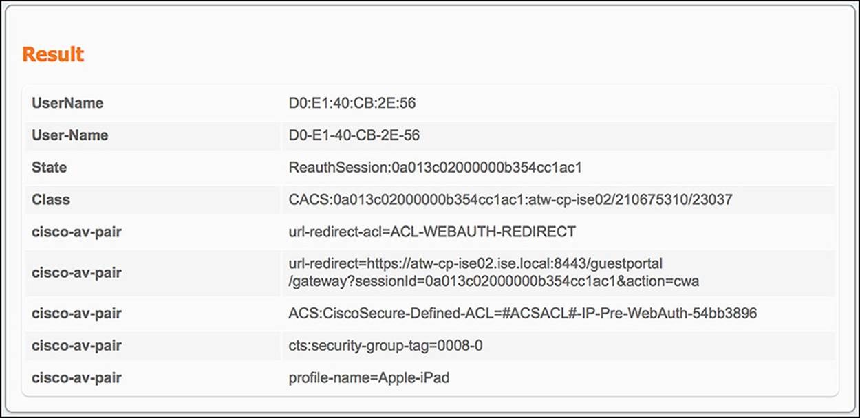
Figure 14-47 ISE Authentication Details Live Log—Wireless WebAuth results.
5. ISE gets the final authentication request and sends the WLC the Internet_Only authorization profile and SGA policy GUEST—When the guest user authenticates to the web portal, a CoA will be sent to the WLC on his behalf, forcing the endpoint to reauthorize. If the guest user’s web authentication is successful, the user should be given the authorization policy of Internet_Only and an SGA policy GUEST. The conditions that must match for this to happen are Guest user identity store and Network Access:UseCase = Guest Flow. This final authentication request should result in the following communications (see Figure 14-48):
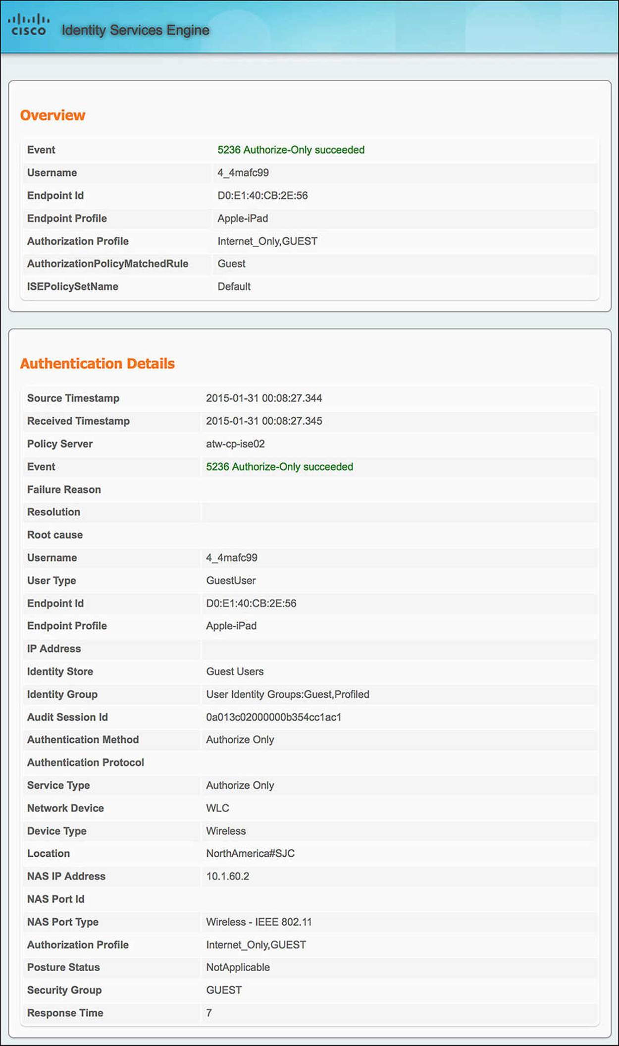
Figure 14-48 ISE Authentication Details Live Log—Wireless Internet_Only.
![]() From WLC to ISE—Looking at the authentication details for the endpoint in question, we will focus on the Overview and Authentication Details section of the output.
From WLC to ISE—Looking at the authentication details for the endpoint in question, we will focus on the Overview and Authentication Details section of the output.
![]() Authorization profile—Under the Overview, you will get the condensed version of the authorization output. Looking at the authorization profile, you will see Internet_Only and GUEST. These are the authorization profile and SGA policy you should be seeing.
Authorization profile—Under the Overview, you will get the condensed version of the authorization output. Looking at the authorization profile, you will see Internet_Only and GUEST. These are the authorization profile and SGA policy you should be seeing.
![]() AuthorizationPolicyMatchedRule—In the case of a successful guest user web authentication and reauthorization, this rule should be Guest.
AuthorizationPolicyMatchedRule—In the case of a successful guest user web authentication and reauthorization, this rule should be Guest.
![]() Endpoint ID—When looking at the authentication details for a particular endpoint, ensure that you are looking at the MAC address of the correct endpoint.
Endpoint ID—When looking at the authentication details for a particular endpoint, ensure that you are looking at the MAC address of the correct endpoint.
![]() Authentication method—With a CoA, there will not be a need to authenticate. Therefore, this output should be Authorize Only.
Authentication method—With a CoA, there will not be a need to authenticate. Therefore, this output should be Authorize Only.
![]() Identity group—Because the guest user is a part of the Guest identity group, this identity group list should contain User Identity Groups:Guest.
Identity group—Because the guest user is a part of the Guest identity group, this identity group list should contain User Identity Groups:Guest.
![]() Use case—The other condition, besides the Guest identity group, is GuestFlow, which is equal to Network Access:UseCase EQUALS Guest Flow. Under Other Attributes, you will see UseCase equals Guest Flow.
Use case—The other condition, besides the Guest identity group, is GuestFlow, which is equal to Network Access:UseCase EQUALS Guest Flow. Under Other Attributes, you will see UseCase equals Guest Flow.
Because the Guest rule has the two conditions of Guest identity group and GuestFlow, and because both of these conditions are matched, the authorization profile of Internet_Only and SGA policy of GUEST must be pushed back to the WLC. The information in this authorization profile is provided in the Result section of the authentication details. This output (shown in Figure 14-49) is as follows:
![]() From ISE to WLC—The Result section of the authentication live log shows
From ISE to WLC—The Result section of the authentication live log shows
![]() Airespace-ACL-Name—The Airespace ACL name is a named ACL pushed to the NAD on behalf the endpoint. This named ACL, Internet-Only, will ensure that the endpoint can access only non-RFC1918 address space.
Airespace-ACL-Name—The Airespace ACL name is a named ACL pushed to the NAD on behalf the endpoint. This named ACL, Internet-Only, will ensure that the endpoint can access only non-RFC1918 address space.
![]() Security Group Tag—The SGT that was assigned to the endpoint can also be found in the Result section of the Authentication details. Again, this value will be embedded in a cisco-av-pair—namely the AV pair of cts:security-group-tag=0008-0. This is the same SGT value that was pushed in the WebAuth scenario.
Security Group Tag—The SGT that was assigned to the endpoint can also be found in the Result section of the Authentication details. Again, this value will be embedded in a cisco-av-pair—namely the AV pair of cts:security-group-tag=0008-0. This is the same SGT value that was pushed in the WebAuth scenario.
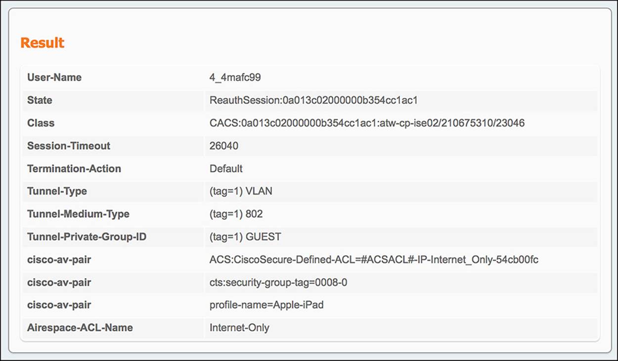
Figure 14-49 ISE Authentication Details Live Log—Wireless Internet_Only results.
Switch
In a similar fashion as a wireless guest user, the wired guest user will also go through a number of distinct steps to authenticate to the network. The overall flow is mostly the same, except some of the RADIUS exchanges change from the wireless to the wired counterpart. Let’s look at each of the steps in detail:
1. The endpoint plugs into a switchport that is configured for MAB—In the WLC, MAB was configured as MAC Filtering. On a switch, the switchport must be explicitly configured for MAB. In many cases, the port is configured for dot1x first and foremost, with a failover option of MAB. That is the case with this scenario.
2. Because the port is configured for dot1x, we’ll need to confirm that it fails over to MAB—As mentioned previously, in most scenarios, dot1x is the preferred authentication method. Therefore, the wired guest user must wait until dot1x fails to receive a response. This will result in a successful MAB authentication. You can monitor the status of the authentication process by running the command show authentication sessions interface <if_name> details.
3. The initial authorization policy pushed to the endpoint must be CWA and SGA policy of GUEST—The output of show authentication sessions interface <if_name> details shows the RADIUS Attribute-Value pairs that are sent to the switch (see Example 14-3).
Example 14-3 show authentication sessions interface <if_name> details
KR-3750#show authentication sessions interface GigabitEthernet 1/0/3 details
Interface: GigabitEthernet1/0/3
MAC Address: 0017.f2cb.5c34
IPv6 Address: Unknown
IPv4 Address: 10.116.43.138
User-Name: 00-17-F2-CB-5C-34
Status: Authorized
Domain: DATA
Oper host mode: multi-auth
Oper control dir: both
Session timeout: N/A
Common Session ID: 0A742B860000003B0231777D
Acct Session ID: 0x00000049
Handle: 0x2B000029
Current Policy: POLICY_Gi1/0/3
Local Policies:
Template: DEFAULT_LINKSEC_POLICY_SHOULD_SECURE (priority 150)
Security Policy: Should Secure
Security Status: Link Unsecure
Server Policies:
URL Redirect: https://atw-cp-ise02.ise.local:8443/guestportal/
gateway?sessionId=0A742B860000003B0231777D&action=cwa
URL Redirect ACL: ACL-WEBAUTH-REDIRECT
ACS ACL: xACSACLx-IP-Pre-WebAuth-54bb3896
SGT Value: 8
Method status list:
Method State
dot1x Stopped
mab Authc Success
Looking at this output, we can see the following information is pushed to the NAD:
![]() MAC Address—Again, confirm that the MAC address matches the endpoint in question.
MAC Address—Again, confirm that the MAC address matches the endpoint in question.
![]() Status—The status of the endpoint should be Authorized. If it is not Authorized, you might have a communication or policy issue on the ISE server.
Status—The status of the endpoint should be Authorized. If it is not Authorized, you might have a communication or policy issue on the ISE server.
![]() URL Redirect—The redirect URL is the URL for the WebAuth portal for the guest user. Because the guest user attempts to browse to a website, this redirect will send the user to ISE to authenticate. This URL will point to one of the ISE PSNs.
URL Redirect—The redirect URL is the URL for the WebAuth portal for the guest user. Because the guest user attempts to browse to a website, this redirect will send the user to ISE to authenticate. This URL will point to one of the ISE PSNs.
![]() URL Redirect ACL—The URL redirect ACL is the ACL used for web redirection. This named ACL was defined as ACL-WEBAUTH-REDIRECT on the CWA policy on ISE.
URL Redirect ACL—The URL redirect ACL is the ACL used for web redirection. This named ACL was defined as ACL-WEBAUTH-REDIRECT on the CWA policy on ISE.
![]() ACS ACL—The ACL Pre-WebAuth is a DACL pushed from ISE as part of the CWA policy. As a DACL is pushed from ISE, ISE will make a copy of the ACL for each endpoint, giving each DACL a unique identifier. In this case, the DACL was given the per-username xACSACLx-IP-Pre-WebAuth-54bb3896.
ACS ACL—The ACL Pre-WebAuth is a DACL pushed from ISE as part of the CWA policy. As a DACL is pushed from ISE, ISE will make a copy of the ACL for each endpoint, giving each DACL a unique identifier. In this case, the DACL was given the per-username xACSACLx-IP-Pre-WebAuth-54bb3896.
![]() SGT Value—The SGA policy of GUEST assigns the SGT of 8 to the endpoint. You can see that value here under the variable SGT value.
SGT Value—The SGA policy of GUEST assigns the SGT of 8 to the endpoint. You can see that value here under the variable SGT value.
![]() Method Status List—The method status list is a list of the authentication methods that can be used to authenticate a client. This list should indicate a success (such as an Authc Success) for the MAB method. The other methods that might be available may be in a Stopped state. You can see that dot1x is in a Stopped state in this example.
Method Status List—The method status list is a list of the authentication methods that can be used to authenticate a client. This list should indicate a success (such as an Authc Success) for the MAB method. The other methods that might be available may be in a Stopped state. You can see that dot1x is in a Stopped state in this example.
4. The final authorization policy pushed to the endpoint must be Internet_Only and SGA policy of GUEST—Again, looking at the output of show authentication sessions interface <if_name> details, we see the following policy is pushed to the NAD (see Example 14-4).
Example 14-4 show authentication sessions interface <if_name> details
KR-3750#show authentication sessions interface GigabitEthernet 1/0/3 details
Interface: GigabitEthernet1/0/3
MAC Address: 0017.f2cb.5c34
IPv6 Address: Unknown
IPv4 Address: 10.116.43.138
User-Name: ~68j1r6oz
Status: Authorized
Domain: DATA
Oper host mode: multi-auth
Oper control dir: both
Session timeout: N/A
Common Session ID: 0A742B860000003B0231777D
Acct Session ID: 0x00000049
Handle: 0x2B000029
Current Policy: POLICY_Gi1/0/3
Local Policies:
Template: DEFAULT_LINKSEC_POLICY_SHOULD_SECURE (priority 150)
Security Policy: Should Secure
Security Status: Link Unsecure
Server Policies:
ACS ACL: xACSACLx-IP-Internet_Only-54cb00fc
SGT Value: 8
Method status list:
Method State
dot1x Stopped
mab Authc Success
![]() MAC Address—Always check the MAC address!
MAC Address—Always check the MAC address!
![]() Status—As before, the status of the endpoint should be Authorized. If it is not Authorized, you might have a communication or policy issue on the ISE server.
Status—As before, the status of the endpoint should be Authorized. If it is not Authorized, you might have a communication or policy issue on the ISE server.
![]() URL Redirect—The URL redirect will no longer be present after the endpoint has authenticated via WebAuth.
URL Redirect—The URL redirect will no longer be present after the endpoint has authenticated via WebAuth.
![]() URL Redirect ACL—As was the case with the URL redirect, the URL redirect will also no longer be needed after the endpoint has authenticated via WebAuth.
URL Redirect ACL—As was the case with the URL redirect, the URL redirect will also no longer be needed after the endpoint has authenticated via WebAuth.
![]() ACS ACL—The ACL Internet_Only is a DACL pushed from ISE as part of the Internet_Only policy. As was the case with the Pre-WebAuth ACL, ISE will make a copy of the ACL for each endpoint, giving each instance of the DACL a unique identifier. In this case, the DACL was given the per-username xACSACLx-IP-Internet_Only-54cb00fc.
ACS ACL—The ACL Internet_Only is a DACL pushed from ISE as part of the Internet_Only policy. As was the case with the Pre-WebAuth ACL, ISE will make a copy of the ACL for each endpoint, giving each instance of the DACL a unique identifier. In this case, the DACL was given the per-username xACSACLx-IP-Internet_Only-54cb00fc.
![]() SGT Value—The SGA policy of GUEST, as before, does not change. You can see that value here under the variable SGT value.
SGT Value—The SGA policy of GUEST, as before, does not change. You can see that value here under the variable SGT value.
![]() Method status list—The method status list is a list of the authentication methods that can be used to authenticate a client. This list should indicate a success (such as an Authc Success) for the MAB method because we are still using MAB. The other methods that might be available may be in a Stopped state. You can see that dot1x is in a Stopped state in this example.
Method status list—The method status list is a list of the authentication methods that can be used to authenticate a client. This list should indicate a success (such as an Authc Success) for the MAB method because we are still using MAB. The other methods that might be available may be in a Stopped state. You can see that dot1x is in a Stopped state in this example.
Now that we have validated the endpoint’s connection from the standpoint of the switch, we can take a look at ISE, highlighting the communications sent between the switch and ISE and the return traffic. When we look at the ISE authentication details for the initial (WebAuth) authorization and the final (Internet_Only) authorization, we must ensure that all authorization conditions are met from the switch and that the ISE pushes the correct information back to the switch in both cases.
5. ISE gets the initial authentication request and sends the switch the CWA authorization profile and SGA policy GUEST—When the endpoint first plugs into the switch, the switch will send a MAB request to ISE. For the endpoint to hit the WebAuth policy, the switch must meet the conditions of Wired_MAB (or Wireless_MAB, but we know that this endpoint is wired). This initial authentication request should result in the following communications:
![]() From switch to ISE—Looking at the authentication details for the endpoint in question (the magnifying glass in the Details column of the Authentication Live Log), there are a number of sections in the output. For the communication from the NAD, you will need to look at the Overview and Authentication Details section of the output (see Figure 14-50).
From switch to ISE—Looking at the authentication details for the endpoint in question (the magnifying glass in the Details column of the Authentication Live Log), there are a number of sections in the output. For the communication from the NAD, you will need to look at the Overview and Authentication Details section of the output (see Figure 14-50).
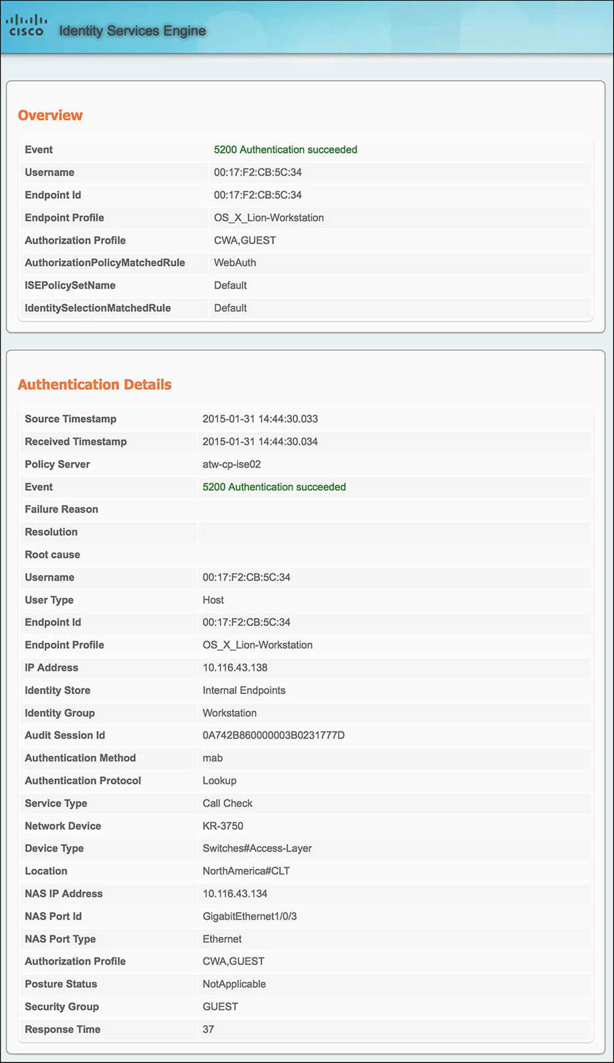
Figure 14-50 ISE Authentication Details Live Log—Wired WebAuth.
![]() Authorization Profile—The Overview shows the condensed version of the authorization output. Looking at the authorization profile, you will see CWA and GUEST. These are the authorization profile and SGA policy you should be seeing based on the WebAuth rule.
Authorization Profile—The Overview shows the condensed version of the authorization output. Looking at the authorization profile, you will see CWA and GUEST. These are the authorization profile and SGA policy you should be seeing based on the WebAuth rule.
![]() AuthorizationPolicyMatchedRule—This variable tells us the name of the authorization rule we hit. In the case of a guest authenticating to the network, the rule we should hit is indeed WebAuth.
AuthorizationPolicyMatchedRule—This variable tells us the name of the authorization rule we hit. In the case of a guest authenticating to the network, the rule we should hit is indeed WebAuth.
![]() Endpoint ID—When looking at the authentication details for a particular endpoint, ensure that you are looking at the MAC address of the correct endpoint.
Endpoint ID—When looking at the authentication details for a particular endpoint, ensure that you are looking at the MAC address of the correct endpoint.
![]() Authentication Method—The authentication method as shown on the authentication details should be MAB.
Authentication Method—The authentication method as shown on the authentication details should be MAB.
![]() Service Type—The service type for a MAB connection from a Cisco switch should be Call Check.
Service Type—The service type for a MAB connection from a Cisco switch should be Call Check.
![]() NAS Port Type—The NAS port type for a wired connection should be Ethernet.
NAS Port Type—The NAS port type for a wired connection should be Ethernet.
Because Wired_MAB is defined by a service type of Call Check and a NAS port type of Ethernet, the conditions for the CWA authorization profile and SGA policy of GUEST have been met. ISE must now send the resulting authorization profile back to the switch. The information in this authorization profile is provided in the Result section of the authentication details (see Figure 14-51). Looking at this output, we see:
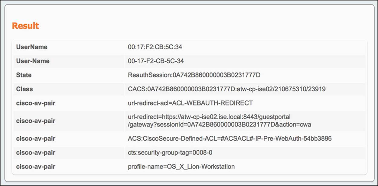
Figure 14-51 ISE Authentication Details Live Log—Wired WebAuth results.
![]() From ISE to switch—The output in the Result section of the Authentication Live Log is as follows:
From ISE to switch—The output in the Result section of the Authentication Live Log is as follows:
![]() URL Redirect—The redirect URL is contained within one of the cisco-av-pair outputs, specifically the one that begins with url-redirect=. As you look at the rest of the URL, you will notice that there is a parameter called action=cwa. As the endpoint is redirected to that URL, ISE recognizes this parameter as a CWA call and provides the endpoint the correct webpage.
URL Redirect—The redirect URL is contained within one of the cisco-av-pair outputs, specifically the one that begins with url-redirect=. As you look at the rest of the URL, you will notice that there is a parameter called action=cwa. As the endpoint is redirected to that URL, ISE recognizes this parameter as a CWA call and provides the endpoint the correct webpage.
![]() URL Redirect ACL—The redirect ACL is also contained within one of the cisco-av-pair outputs in the Result section. In this case, the cisco-av-pair will begin with url-redirect-acl= (notice the acl at the end), specifically mentioning the ACL-WEBAUTH-REDIRECT ACL.
URL Redirect ACL—The redirect ACL is also contained within one of the cisco-av-pair outputs in the Result section. In this case, the cisco-av-pair will begin with url-redirect-acl= (notice the acl at the end), specifically mentioning the ACL-WEBAUTH-REDIRECT ACL.
![]() ACS ACL—The DACL that is sent from ISE is also one of the cisco-av-pair outputs—the one with the attribute of ACS:CiscoSecure-Defined-ACL. The value, #ACSACL#-IP-Pre-WebAuth-54bb3896, is unique on a per-user basis.
ACS ACL—The DACL that is sent from ISE is also one of the cisco-av-pair outputs—the one with the attribute of ACS:CiscoSecure-Defined-ACL. The value, #ACSACL#-IP-Pre-WebAuth-54bb3896, is unique on a per-user basis.
![]() Security Group Tag—The SGT that was assigned to the endpoint can also be found in the Result section of the authentication details. Again, this value will be embedded in a cisco-av-pair—namely, the AV pair of cts:security-group-tag=0008-0.
Security Group Tag—The SGT that was assigned to the endpoint can also be found in the Result section of the authentication details. Again, this value will be embedded in a cisco-av-pair—namely, the AV pair of cts:security-group-tag=0008-0.
Supplementing this authorization output, ISE will also create a separate log in the Authentication Live Log for the DACL that is pushed to the NAD on behalf of the endpoint. Looking at the authentication details for this DACL (see Figure 14-52), focusing on the Results section, you will see the individual lines of the ACL that is pushed to the NAD.
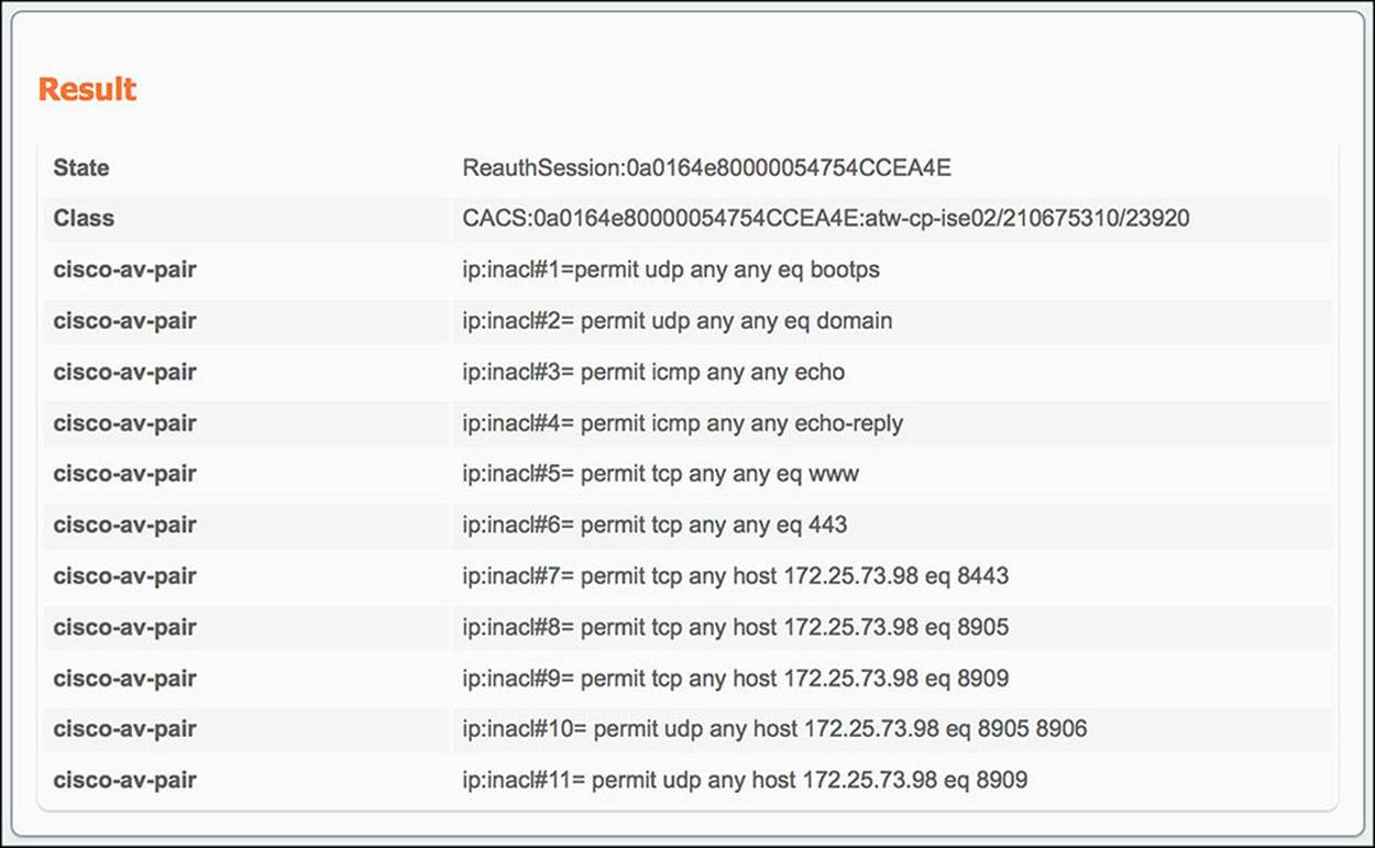
Figure 14-52 ISE Authentication Details Live Log—Wired WebAuth—Pre-WebAuth DACL.
6. ISE gets the final authentication request and sends the switch the Internet_Only authorization profile and SGA policy GUEST—When the guest user authenticates to the web portal, a CoA will be sent to the switch on her behalf, forcing the endpoint to reauthorize. If the guest user’s web authentication is successful, the user should be given the authorization policy of Internet_Only and a SGA policy GUEST. The conditions that must match for this to happen are Guest user identity store and Network Access:UseCase = Guest Flow. This final authentication request should result in the following communications:
![]() From switch to ISE—Looking at the authentication details (shown in Figure 14-53) for the endpoint in question, we will focus on the Overview and Authentication Details section of the output.
From switch to ISE—Looking at the authentication details (shown in Figure 14-53) for the endpoint in question, we will focus on the Overview and Authentication Details section of the output.
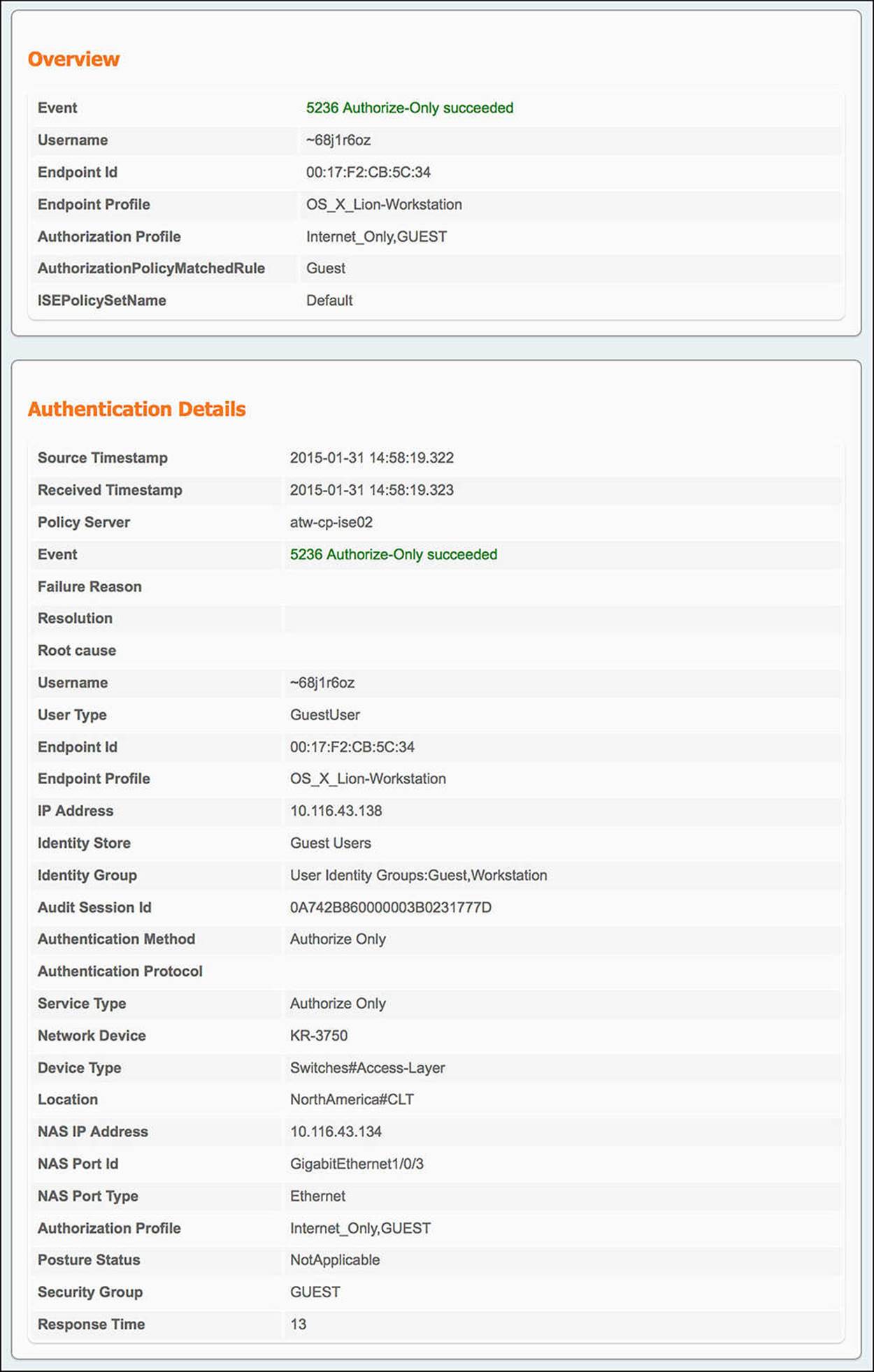
Figure 14-53 ISE Authentication Details Live Log—Wired Internet_Only.
![]() Authorization Profile—Under the Overview, you will get the condensed version of the authorization output. Looking at the Authorization Profile, you will see Internet_Only and GUEST. These are the authorization profile and SGA policy that we should be seeing.
Authorization Profile—Under the Overview, you will get the condensed version of the authorization output. Looking at the Authorization Profile, you will see Internet_Only and GUEST. These are the authorization profile and SGA policy that we should be seeing.
![]() AuthorizationPolicyMatchedRule—In the case of a successful guest user web authentication and reauthorization, this rule should be Guest.
AuthorizationPolicyMatchedRule—In the case of a successful guest user web authentication and reauthorization, this rule should be Guest.
![]() Endpoint ID—When looking at the authentication details for a particular endpoint, ensure that you are looking at the MAC address of the correct endpoint.
Endpoint ID—When looking at the authentication details for a particular endpoint, ensure that you are looking at the MAC address of the correct endpoint.
![]() Authentication Method—With a CoA, there will not be a need to authenticate. Therefore, this output should be Authorize Only.
Authentication Method—With a CoA, there will not be a need to authenticate. Therefore, this output should be Authorize Only.
![]() Identity Group—As the guest user is a part of the Guest identity group, this list of identity groups should contain User Identity Groups:Guest.
Identity Group—As the guest user is a part of the Guest identity group, this list of identity groups should contain User Identity Groups:Guest.
![]() Use Case—The other condition, besides the Guest identity group, is GuestFlow, which is equal to Network Access:UseCase EQUALS Guest Flow. Under Other Attributes, you will see UseCase equals Guest Flow.
Use Case—The other condition, besides the Guest identity group, is GuestFlow, which is equal to Network Access:UseCase EQUALS Guest Flow. Under Other Attributes, you will see UseCase equals Guest Flow.
Because the Guest rule has the two conditions of Guest identity group and GuestFlow—and because both of these conditions are matched—the Authorization profile of Internet_Only and SGA policy of GUEST must be pushed back to the switch. The information in this authorization profile is provided in the Result section of the authentication details. Looking at this output (see Figure 14-54), we see:
![]() From ISE to Switch—Looking at the output in the Result section of the Authentication Live Log:
From ISE to Switch—Looking at the output in the Result section of the Authentication Live Log:
![]() ACS ACL—The DACL that is sent from ISE is also one of the cisco-av-pair outputs—the one with the attribute of ACS:CiscoSecure-Defined-ACL. The value, #ACSACL#-IP-Internet_Only-54cb00fc, again, is unique on a per-user basis.
ACS ACL—The DACL that is sent from ISE is also one of the cisco-av-pair outputs—the one with the attribute of ACS:CiscoSecure-Defined-ACL. The value, #ACSACL#-IP-Internet_Only-54cb00fc, again, is unique on a per-user basis.
![]() Security Group Tag—The SGT that was assigned to the endpoint can also be found in the Result section of the authentication details. Again, this value will be embedded in a cisco-av-pair—namely the AV pair of cts:security-group-tag=0008-0. This is the same SGT value that was pushed in the WebAuth scenario.
Security Group Tag—The SGT that was assigned to the endpoint can also be found in the Result section of the authentication details. Again, this value will be embedded in a cisco-av-pair—namely the AV pair of cts:security-group-tag=0008-0. This is the same SGT value that was pushed in the WebAuth scenario.
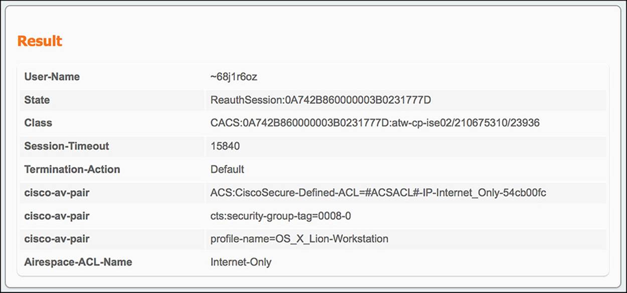
Figure 14-54 ISE Authentication Details Live Log—Wired Internet_Only Results.
Again, ISE will also create a separate log in the Authentication Live Log for the DACL that is pushed to the NAD on behalf of the endpoint. Looking at the authentication details for this DACL (see Figure 14-55), focusing on the Results section, you will see the individual lines of the ACL that is pushed to the NAD.
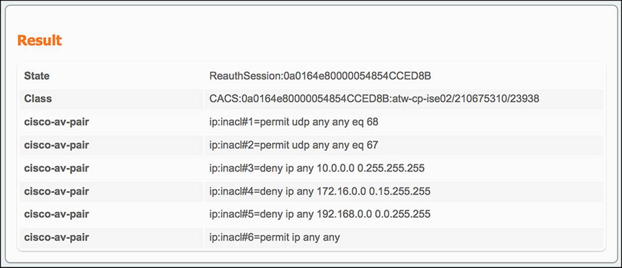
Figure 14-55 ISE Authentication Details Live Log—Wired Internet Only—Internet_Only DACL.
In both the WLC and switch use cases, the guest user was sent to a webpage to complete the WebAuth process. This WebAuth process will also create an Authentication Live Log. This allows the administrator to confirm if the user is typing the correct username and/or password during the login process. All the information within this Live Log is maintained locally and doesn’t get sent explicitly to the NAD. Let’s take a quick look at the key fields in the WebAuth Live Log (see Figure 14-56).
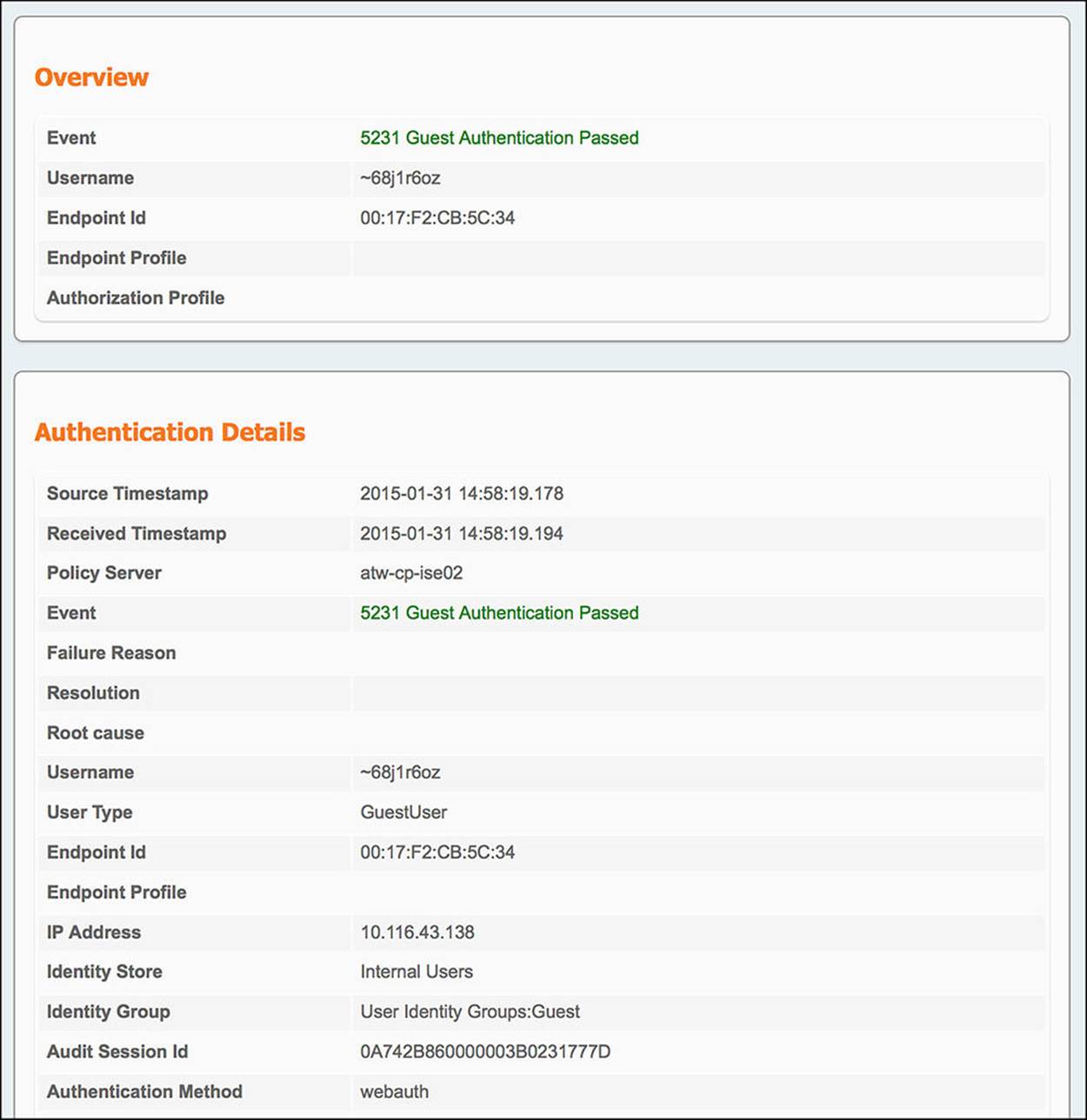
Figure 14-56 ISE Authentication Details Live Log—WebAuth.
![]() Username—Within the Overview section, you will see the guest user username. Confirm that this username was typed correctly by the user.
Username—Within the Overview section, you will see the guest user username. Confirm that this username was typed correctly by the user.
![]() Endpoint Id—As before, make sure that you are looking at the correct Live Log for the endpoint using the endpoints MAC address for confirmation.
Endpoint Id—As before, make sure that you are looking at the correct Live Log for the endpoint using the endpoints MAC address for confirmation.
![]() Identity Group—The Identity Group list in this case should contain User Identity Groups:Guest.
Identity Group—The Identity Group list in this case should contain User Identity Groups:Guest.
![]() Authentication Method—Because the guest user will be logging in directly to the webpage in this scenario, the Authentication Method should be webauth.
Authentication Method—Because the guest user will be logging in directly to the webpage in this scenario, the Authentication Method should be webauth.
![]() PortalName—In the Other Attributes section of the authentication details, you will see which guest portal was used to process this authentication request.
PortalName—In the Other Attributes section of the authentication details, you will see which guest portal was used to process this authentication request.
The Authentication Live Log output is extremely useful when troubleshooting the communication between a NAD and ISE or a user and ISE. In both of these cases, comparing the conditions and result of the authorization policy that the user or endpoint DID hit versus the conditions and result of the authorization that the user or endpoint SHOULD HAVE hit will usually point you toward any policy issues on ISE.
Exam Preparation Tasks
Review All Key Topics
Review the most important topics in the chapter, noted with the key topics icon in the outer margin of the page. Table 14-3 lists a reference of these key topics and the page numbers on which each is found.

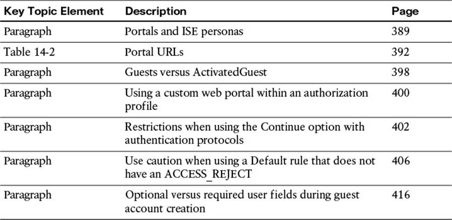
Table 14-3 Key Topics for Chapter 14
Define Key Terms
Define the following key terms from this chapter, and check your answers in the glossary:
sponsor