CCNP Security SISAS 300-208 Official Cert Guide (2015)
Part III: Cisco Identity Services Engine
Chapter 7. Cisco Identity Services Engine Architecture
This chapter covers the following exam topics:
![]() What Is Cisco ISE?
What Is Cisco ISE?
![]() Personas
Personas
![]() Physical or virtual appliance
Physical or virtual appliance
![]() Cisco ISE deployment scenarios
Cisco ISE deployment scenarios
Up to this point, we’ve looked generically at several key components of a network security architecture, highlighting the fundamentals of AAA, identity management, EAP/802.1X, and advanced concepts. In this chapter, we take our first look at Cisco’s Identity Services Engine specifically. We provide a general description of Cisco ISE, the various personas that ISE will assume, physical and virtual instantiations of ISE, as well as several common Cisco ISE deployment scenarios.
“Do I Know This Already?” Quiz
The “Do I Know This Already?” quiz allows you to assess whether you should read this entire chapter thoroughly or jump to the “Exam Preparation Tasks” section. If you are in doubt about your answers to these questions or your own assessment of your knowledge of the topics, read the entire chapter. Table 7-1 lists the major headings in this chapter and their corresponding “Do I Know This Already?” quiz questions. You can find the answers in Appendix A, “Answers to the ‘Do I Know This Already?’ Quizzes.”
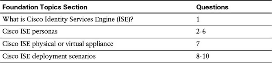
Table 7-1 “Do I Know This Already?” Section-to-Question Mapping
Caution
The goal of self-assessment is to gauge your mastery of the topics in this chapter. If you do not know the answer to a question or are only partially sure of the answer, you should mark that question as wrong for purposes of the self-assessment. Giving yourself credit for an answer you correctly guess skews your self-assessment results and might provide you with a false sense of security.
1. Cisco Identity Services Engine (ISE) is which of the following?
a. A switch that provides authenticated access to the network
b. A network management platform
c. A network security and policy platform
d. A unified computing system that incorporates virtualization of endpoints
2. The four key personas of Cisco ISE are which of the following? (Select four.)
a. Administration
b. Authentication Server
c. File Download
d. Monitoring and Troubleshooting
e. Policy Services Node
f. Identity Management
g. Inline Posture Node
3. The Cisco ISE Administration Node persona is which of the following?
a. The node where policy configuration changes are made
b. The network management platform for the network
c. The engine where policy decisions are made
d. Responsible for logging and reporting data
4. The Cisco ISE Monitoring and Troubleshooting Node persona is which of the following?
a. The node where policy configuration changes are made
b. The network management platform for the network
c. The engine where policy decisions are made
d. Responsible for logging and reporting data
5. The Cisco ISE Policy Service Node persona is which of the following?
a. The node where policy configuration changes are made
b. The network management platform for the network
c. The engine where policy decisions are made
d. Responsible for logging and reporting data
6. Which of the following is true about the Cisco ISE Inline Posture Node persona?
a. A gatekeeper that enforces access policies and handles CoA requests, specifically for those that cannot process CoA requests
b. Is an ergonomic tool included within Cisco ISE to ensure that network administrators are not slouching on the job
c. Allows users to always bypass authentication and authorization, giving them unfettered access to the network.
d. Sniffs all the packets sent from an endpoint, inline, making sure that the endpoint is not distributing viruses and malware onto the network.
7. A virtual ISE appliance should do which of the following?
a. Be kept as small as possible for speed and agility
b. Be appropriately sized to match the equivalent physical appliance
c. Reserve the appropriate resources to ensure that other virtualized applications do not cannibalize the ISE resources
d. A and B
e. B and C
f. A, B, and C
8. In a single-node/standalone deployment of ISE which of the following is true?
a. Each ISE appliance services a single network access device.
b. Each ISE appliance services only a single ISE persona.
c. All endpoints bypass authentication.
d. All core ISE personas reside on a single ISE appliance.
9. In a four-node deployment of Cisco ISE, the ____ and ____ personas are combined on two of the appliances, while the ____ persona is by itself on each of the other two appliances.
a. PAN, PSN, MNT
b. PAN, IPN, MNT
c. PSN, MNT, IPN
d. PSN, PAN, MNT
e. PAN, MNT, IPN
f. PAN, MNT, PSN
10. The maximum number of PSNs supported with ISE 1.2 in a fully distributed deployment model is ____, resulting in a maximum number of supported endpoints of ______.
a. 5; 5,000
b. 5; 10,000
c. 5; 50,000
d. 40; 5,000
e. 40; 20,000
f. 40; 250,000
Foundation Topics
What Is Cisco ISE?
Cisco’s Identity Services Engine (ISE) is a security policy management platform and a key component of the Cisco secure access architecture. Its role within the network enables it to be the enforcement point for network security.
Network security is often delegated to singular devices within the network. For instance, you might allow unfettered access for all endpoints within the core of your corporate network and enforce the access policy at the edge firewall. For your wireless users, you might choose to enforce a singular policy for all users allowing every wireless user access to HTTP, HTTPS, SSH, and Telnet and implementing this policy at the access point (autonomous mode) or at the Wireless LAN Controller (lightweight mode). This “one-size-fits-all” approach is not the ideal way to implement network security.
Cisco ISE helps facilitate this paradigm shift of making the network—not a singular device—the enforcement point for network security. This is made possible via RADIUS. Remote Authentication Dial-In User Service (RADIUS) provides authentication, authorization, and accounting (AAA). Cisco ISE acts as a centralized, network security policy platform and RADIUS server, extending this AAA functionality to all network devices. As a user or an endpoint attempts to access the network, the network access device (NAD) forwards all relevant authentication parameters to Cisco ISE. Cisco ISE responds to the NAD with the resulting security policy to be applied to the user or endpoint by using RADIUS Attribute-Value Pairs (AVPs).
The authorization policy sent to the NAD is implemented on a per-user basis. By tightly coupling the authorization of the user with the authentication, a network administrator can provide differentiated network access to all users. If you are a basic user, your level of network access is likely going to be different than if you are a network administrator. Your level of access also might change whether you are accessing the network using wireless versus wired or whether you are accessing the network from a remote branch location or from the campus network. The granular policy building blocks available in Cisco ISE ensure that the network administrator can implement the best network security policy either on a per-user or per-group basis.
Besides the basic functions provided as a RADIUS server, Cisco ISE also provides several advanced functions. Natively integrated within Cisco ISE, profiling can dynamically identify endpoints. As an endpoint attempts to access the network, ISE can profile the device, identifying, managing, and taking inventory of the devices accessing the network based on a predefined security policy. This profiling operation can determine the manufacturer of the endpoint, the function of the endpoint (IP phone, IP camera, or network printer), as well as other network-level assessments of the endpoint. The result of this profiling operation can also be used as one more criteria in the authorization policy that is applied to the endpoint.
Another advanced function available within Cisco ISE is posturing. Posturing can go slightly deeper than what is provided via profiling by using a slightly different approach. Where profiling uses network-level communications to determine information about the endpoint, posturing leverages information that resides on the endpoint. Using a network access control (NAC) agent that resides on the endpoint directly, posturing will ensure that the endpoint is adhering to security policies that have been deployed to the endpoint—policies such as antivirus software, antispyware software, and other security (and even non-security) software and services. If the posture adheres to the implemented security policy on Cisco ISE, additional network access can be allowed via the authorization policy. Conversely, if the endpoint posture does not adhere to the current security policy, a reduced level of network access can be deployed to the NAD on behalf of the endpoint, possibly forcing the endpoint to remediate its noncompliance before gaining access to the network.
The depth of posturing that can be leveraged via Cisco ISE can be further enhanced with third-party software security systems called mobile device managers (MDMs), as described in Chapter 6, “Introduction to Advanced Concepts.” Depending on the chosen MDM, additional industry compliance requirements (including HIPAA and PCI-DSS) can be leveraged by Cisco ISE.
Much of the network security policy we have discussed thus far pertains to corporate-owned assets, or assets that are owned and managed by the enterprise IT department. However, Cisco ISE has a number of features that enable a granular network security policy to be extended to employee-owned or guest endpoints. The employee-owned endpoints, depending on the corporate security policy, can be allowed trusted access equivalent to a corporate-owned asset or basic, Internet-level, guest access.
Trusted level access can be implemented in a number of ways, either by dynamically onboarding the endpoint into the Cisco ISE database (often using an identity management system to identify the user of the device) or by manually adding the device to a trusted device database. Both of these approaches are discussed in future chapters.
Guest-level access is also available natively within ISE, leveraging built-in guest portals. The guest portals available within ISE allow a trusted employee to create temporary guest credentials for visitors, contractors, or other temporary users. These guest credentials then are given to the guest user, either manually or via email, to log in to the network. As the guest user attempts to access the network, a second network portal (or by using network-level authentication such as PEAP) is used to authenticate the user, pushing the relevant guest user access policy to the NAD (wired or wireless) from which the user is accessing the network.
Because Cisco ISE provides a high-level of differentiated access to corporate endpoints, employee endpoints, and guest endpoints enforcing profiling, posturing, and MDM-influenced authorization policy, it is paramount that the network administrators are able to monitor the level of access granted to users and endpoints. This, too, is a feature that is native to Cisco ISE. As each authentication, authorization, profiling, or posturing action occurs, Cisco ISE creates a logging event. These logging events can be filtered, sent to syslog servers, and otherwise searched by network administrators to see the play-by-play of a user’s network authentication and authorization.
Cisco ISE is a one-stop shop for network security policy. By combining an industry-trusted protocol such as RADIUS with the granular, context-based policy that is available with ISE, a network administrator can distribute a unified security policy to the far reaches of his network, ensuring that the security policy deployed to each user and endpoint is as secure as possible.
Personas
As we begin to take a detailed look at Cisco ISE, we will realize that the Cisco ISE is designed with scalability in mind. The manner by which Cisco ISE achieves this is by dividing the roles it provides into separate personas. Each persona is a different function within Cisco ISE that is required for proper operation of the platform.

The three key personas of a Cisco ISE deployment are Administration Node, Policy Service Node, and Monitoring and Troubleshooting Node.
Administration Node
The first, and possibly the most important, persona is the Administration Node. This function of Cisco ISE is important because it is how the network administrator configures and administers the network security policy.
When a network administrator needs to make a change to the security policy—whether it is the authentication, authorization, profiling, posturing, or other policy—on Cisco ISE, the network administrator must access the administrative graphical user interface (GUI). This administrative portal is a Flash-based webpage. Through this Policy Administration Node (PAN, or simply Admin node), which is the central control center for Cisco ISE, all policies are configured and then pushed to other ISE nodes or personas. This Admin node also includes the licensing function for the platform, allowing the network administrator to enable advanced features or additional functionalities within Cisco ISE by installing purchased licenses.
Policy Service Node
The next persona within an ISE deployment is the Policy Service Node (PSN). This PSN persona is the workhorse of the ISE deployment. After making changes on the PAN, all policies are pushed to the PSNs. As a network administrator, each NAD on the network will point to one or more of the ISE PSNs. Additional scalability can be achieved by leveraging a network load balancer, taking into account key implementation requirements including No-NAT, Certificate Subject Alternative Names, and PSN “Stickiness,” amongst others.
When a user authenticates to the network, the NAD forwards the RADIUS Access-Request and subsequent packets to the configured PSN(s). The PSN, having the complete security policy as pushed from the PAN, can authenticate the user and provide the requisite authorization policy.
If the user endpoint is a candidate of any profiling or posturing that is done by ISE, the PSN will also be responsible for deploying a CoA to the endpoint. The NAD also must have the dynamic authorization configuration present, allowing the PSN to force a reauthentication. The CoA is created by the PSN and sent to the NAD without any active participation by the PAN.
Monitoring and Troubleshooting Node
The third persona within an ISE deployment is the Monitoring and Troubleshooting (MnT) Node. The function of this node is exactly as it sounds—to provide monitoring and troubleshooting functions for the Cisco ISE deployment. As an endpoint authenticates to the PSN, events are created to keep track of the authentication and authorization process. These events are forwarded to the MnT Node, which then consolidates and processes these events into a legible format. A network administrator requires reports to be created for whatever purpose, such as managerial slides and presentations, access reports, and so on, and this function is also provided by the MnT node.
The second function of the MnT Node is troubleshooting. With each event that is forwarded to the MnT node, this can be a success or failure of the authentication or authorization process. Due to the detailed event tracking that happens on the Cisco ISE PSNs, the content of the logs present on the MnT are also quite detailed. If a user or endpoint is having any level of issue in accessing the network, a network administrator can leverage the MnT Node to see, firsthand, the cause of the failure and track the user’s or endpoint’s authentication in a play-by-play manner.
A number of PSNs can be deployed in a single ISE deployment, and the MnT acts as a centralized recipient of all logs. Without the centralized monitoring and troubleshooting function that the MnT Node provides, each PSN would be responsible for its own reporting, all while actively participating in ongoing authentication and authorization processes. This could be resource prohibitive. Furthermore, network administrators would need to check the logs on each PSN for event correlation; the MnT, however, provides this function in a single, one-stop-shop approach.
Inline Posture Node
The fourth and final persona within an ISE deployment is the Inline Posture Node (IPN). The IPN can be considered a gatekeeper between a NAD and the rest of the network. The IPN can ensure that the endpoint is adhering to the required security policy before it is given access to the network. The IPN completes a posture assessment of the endpoint, checking antivirus, antispyware, operating system patch level, security parameters including passwords, and other critical system parameters. Upon determining compliance with the security policy, the IPN can then allow the endpoint to access the network at the appropriate level of authorization. If the endpoint fails its compliance check or its compliance status is unknown, the IPN provides appropriate remediation to get the endpoint in compliance. The IPN is also responsible for handling CoA requests for those NADs that are unable to process their own.
Keep in mind that the Inline Posture Node is optional in ISE deployments, required only when the NAD is incapable of handling CoA requests or when additional posture checking is desired.
Physical or Virtual Appliance
Now that you are aware of the various ISE personas, you are better equipped to start the deployment of Cisco ISE on your network. However, there are still a few more decisions you will need to make as you plan for your deployment. The first of these decisions is whether you will deploy physical ISE appliances or will virtualize the Cisco ISE on your network. This section discusses both options. Your decision of whether to use a physical and/or virtual appliance ISE deployment will depend on a number of factors. Several of the key factors impacting this decision include deployment size, budget, scalability, and current network topology.
As we start this discussion of physical versus virtual ISE deployments, we should first highlight what options are available for each approach. The physical appliances come in two form factors:
![]() Cisco Secure Network Server 3415 (SNS-3415)
Cisco Secure Network Server 3415 (SNS-3415)
![]() Cisco Secure Network Server 3495 (SNS-3495)
Cisco Secure Network Server 3495 (SNS-3495)
The SNS-3415 is intended for the smaller size of the deployment scale (5,000 endpoints per server), whereas the SNS-3495 is intended for larger deployments (20,000 endpoints per server in a fully distributed model). See Table 7-2 for the physical appliance specifications. The virtual appliance specifications are provided with specifications to emulate the equivalent hardware appliance. Please see Table 7-3 for that reference.
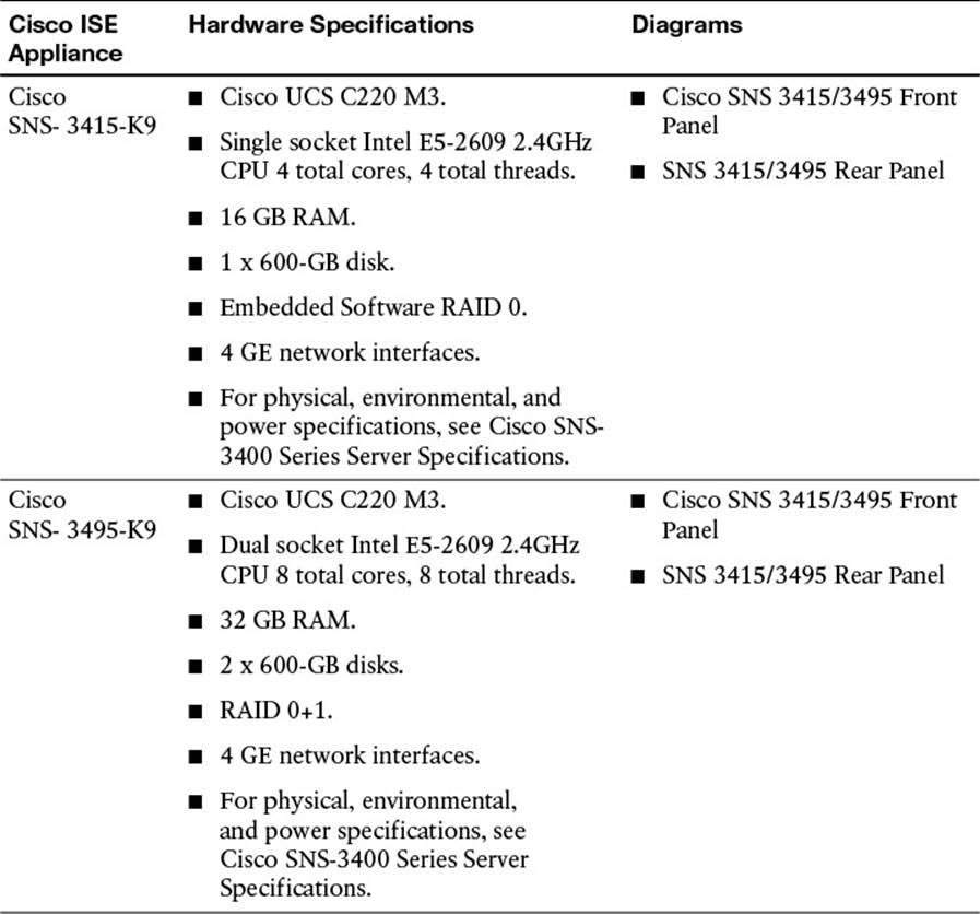
Table 7-2 Cisco ISE Physical Appliance Specifications
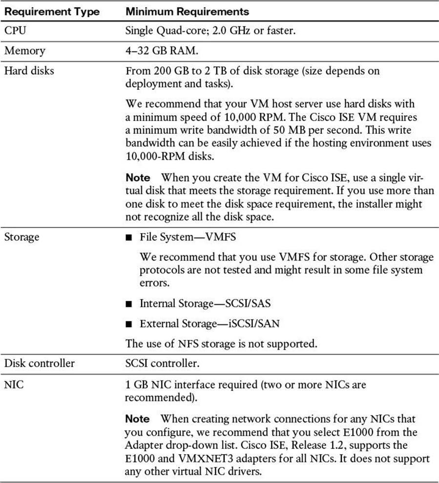
Table 7-3 Cisco ISE Virtual Appliance Specifications
If your current network infrastructure is highly virtualized, you might be considering the virtual appliance approach and leveraging existing Cisco UCS infrastructure. If you choose the virtualized appliance approach for your Cisco ISE deployment, it is best to ensure reservations on the virtual machine (VM) for the entire amount of virtual processors, memory, and hard disk space (refer to Table 7-3). This will guarantee that other VMs are not impacting the proper operation of ISE. Failure to reserve the recommended resources can greatly impact the overall performance and scalability of the Cisco ISE.
Whether you choose to use the virtual or physical ISE appliance, be sure to properly scale your deployment for the anticipated user base and any redundancy that will be required. Deployment scenarios and redundancy are addressed in greater detail in the upcoming section.
ISE Deployment Scenarios
Cisco ISE is not a single physical appliance or virtual machine; it is a highly flexible and scalable security platform. This platform is designed for fault tolerance and to scale to all levels of businesses, from a small mom-and-pop shop to the largest of multinational, global enterprises. As part of this section, we highlight a number of common deployment scenarios, including
![]() Single Node
Single Node
![]() 2 Node
2 Node
![]() 4 Node
4 Node
![]() Fully Distributed
Fully Distributed
As we discuss each of these deployment scenarios, we also need to consider how each Cisco ISE instance communicates with each other node. The term node is used to refer to a physical or virtual instance of the Cisco ISE appliance.
Single-Node Deployment
A single-node, or standalone, deployment of Cisco ISE is the most basic deployment of the Cisco ISE security platform. In this deployment, all ISE personas reside on a single appliance, whether physical or virtual. As we discussed, the various personas earlier in this chapter, whereas each persona has a specific role to serve in the Cisco ISE ecosystem, this single node ISE deployment is responsible for performing all functions on a single device (see Figure 7-1).
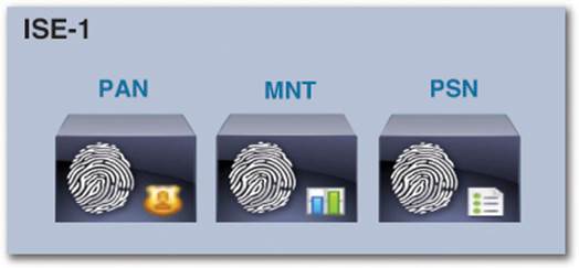
Figure 7-1 Single-node/standalone deployment persona assignment.
Note
The IPN cannot be included in single-node deployments because the IPN requires a dedicated node and cannot assume or share other personas.
Figure 7-2 shows a screen capture of ISE node configuration (Menu > Administration > System > Deployment > <ISE-Host>). If the deployment is standalone (by default), all personas should be selected.
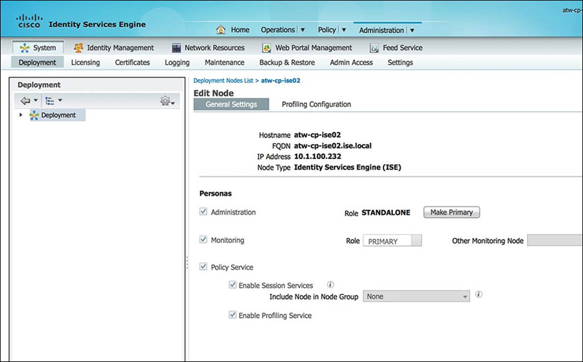
Figure 7-2 Single-node/standalone ISE configuration.
With this single-node, standalone deployment, there is no redundancy. Therefore, if the appliance fails or loses network connectivity for any reason, the ability to provide network authentication and authorization might not exist. The maximum number of supported endpoints in a single-node deployment is 5,000 for the SNS-3415 (or equivalent virtual appliance) and 10,000 for the SNS-3495 (or equivalent virtual appliance).
Because there is no redundancy in this solution and the availability of network resources can be impacted in case of an outage, this deployment is recommended only when testing a solution in a lab environment.
Two-Node Deployment
A two-node deployment of Cisco ISE is the first deployment approach that incorporates redundancy, which is highly recommended in a production network. In this deployment, the various ISE personas are distributed across two appliances. As in the single-node deployment, these appliances can be either physical or virtual appliances. A mixture of physical or virtual appliances also might be considered depending on your network topology and application. Each of the requisite personas—PAN, MNT, and PSN—must be assigned to one or more of the two available appliances. Whenever redundancy is available in this manner, it is sometime referred to as an ISE distributed deployment.
The first appliance, ISE-1, acts as the primary PAN and secondary MNT; the second appliance, ISE-2, acts as the secondary PAN and primary MNT (see Figure 7-3). Both the first and second appliances, ISE-1 and ISE-2, simultaneously act as PSNs. The PSN persona does not recognize a “primary” and “secondary” division of responsibilities, so a PSN is always “active” as soon as the service is enabled on the appliance.
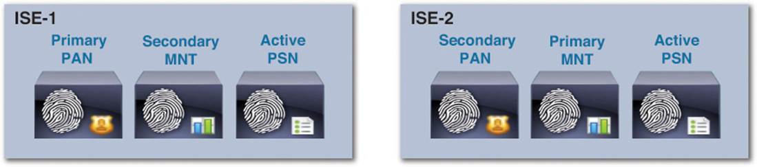
Figure 7-3 Basic two-node deployment persona assignment.
By balancing the primary and secondary roles across the two appliances, each persona is logically and physically distributed across the two appliances, providing the most resilient deployment using only two appliances. If all personas and nodes are working without issue, the load of each ISE server is, for the most part, equally distributed because each of the nodes is actively performing a role in the ISE ecosystem. In case of a failure of a single persona, the secondary instance of the persona on the other node can take over that single role. If a failure of a single appliance occurs, every persona’s role can be provided by the other node.
Because maintaining a single source of truth is paramount to the proper operation of Cisco ISE, failing over from a primary PAN to the secondary PAN is a manual process. If a failure of the primary PAN occurs, no synchronization between the PAN and PSNs will occur until the secondary PAN is promoted to primary. After it becomes primary, synchronization can again resume. This is sometimes referred to as a warm spare.
With regards to the PSN, because a PSN is always “active,” each NAD on the network should point to each PSN. Each NAD will contain a complete RADIUS configuration pointing to both ISE-1 and ISE-2. Depending on the order of the ISE PSN configuration on the NAD, the NAD will choose to use ISE-1 first and ISE-2 as a “secondary/backup,” or vice versa. To provide the best load-balancing of the PSN persona across ISE-1 and ISE-2, you might consider listing ISE-1 as the primary PSN and ISE-2 as the secondary PSN on 50% of the NADs on your network and ISE-2 as the primary PSN and ISE-1 as the secondary PSN on the other 50% of your NADs.
If the PSN persona (and, therefore, RADIUS processing) fails or a single appliance fails, the NAD itself will detect the failure of the RADIUS service on one of the PSNs and direct 100% of future RADIUS queries from that NAD to the remaining PSN. The availability, failover, and recovery detection criterion of the RADIUS service are configured on the NAD. If you want to ensure 100% redundancy of ISE services on your network in a two-node deployment, in case of a single logical or physical failure that would cause a single ISE node to take on 100% of ISE functionality, the maximum number of supported endpoints would be 5,000 for the SNS-3415 and 10,000 for the SNS-3495. If there are greater than the specified number of endpoints, the remaining operational ISE appliance might not be able to single-handedly manage the load.
As shown in Figure 7-2, each ISE host must have the appropriate roles and priorities selected by going to the ISE Node Configuration screen (Menu > Administration > System > Deployment > <ISE-Host>).
Four-Node Deployment
A four-node ISE deployment strategy allows for an equal amount of redundancy as the two-node deployment, with a greater level of persona distribution, further separating the function of each ISE appliance. With a four-node deployment, we will leverage the two-node approach for the PAN and MNT personas. The first appliance, ISE-1, acts as the primary PAN and secondary MNT; the second appliance, ISE-2, acts as the secondary PAN and primary MNT (see Figure 7-4).
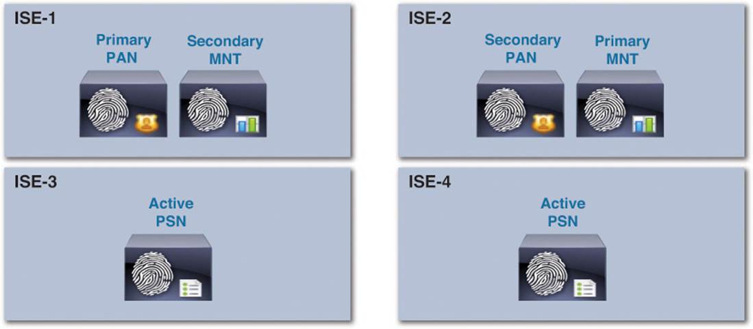
Figure 7-4 Basic four-node deployment persona assignment.
In the two-node deployment, the PSN resides on the each of the ISE nodes, sharing resources with the PAN and MNT personas. However, in the four-node deployment, we separate the administrative functions provided in the PAN and MNT personas from the PSN function. For this reason, ISE-3 and ISE-4 in this four-node deployment are used strictly for the PSN persona.
By separating the PSN persona from the PAN and MNT personas, RADIUS calls to a PSN will continue to function even if the PAN and MNT personas fail. Despite having all PSN functions dedicated to separate appliances, the number of supported endpoints remains the same as in the two-node deployment: 5,000 for the SNS-3415 and 10,000 for the SNS-3495. All other aspects of the four-node deployment will have the same operational features and characteristics as the two-node deployment.
Fully Distributed Deployment
A fully distributed deployment of Cisco ISE separates each persona and places each on a separate appliance. With this deployment model, we place the primary PAN on ISE-1 and the primary MNT on ISE-2, and (if redundancy were required) secondary PANs and MNTs would be deployed on ISE-3 and ISE-4, respectively.
In the four-node deployment, the maximum number of PSNs that can be associated to the combined PAN+MNT is five PSNs, making it a seven-node deployment. If you choose to add more PSNs (up to the maximum of 5), the maximum number of supported endpoints, however, does not increase; these stay at 5,000 and 10,000 endpoints (SNS-3415 and SNS-3495, respectively).
In the fully distributed deployment model, as shown in Figure 7-5, we see much greater scalability. By separating the PAN and MNT personas (using the SNS-3495 for each appliance), a fully distributed deployment can now support up to 250,000 endpoints as a maximum, sustaining approximately 5,000 endpoints per SNS-3415 PSN and approximately 20,000 endpoints per SNS-3495 PSN (an increase from the previous deployment models). The maximum number of PSNs in this deployment model also increases from 5 PSNs to a maximum of 40 PSNs.
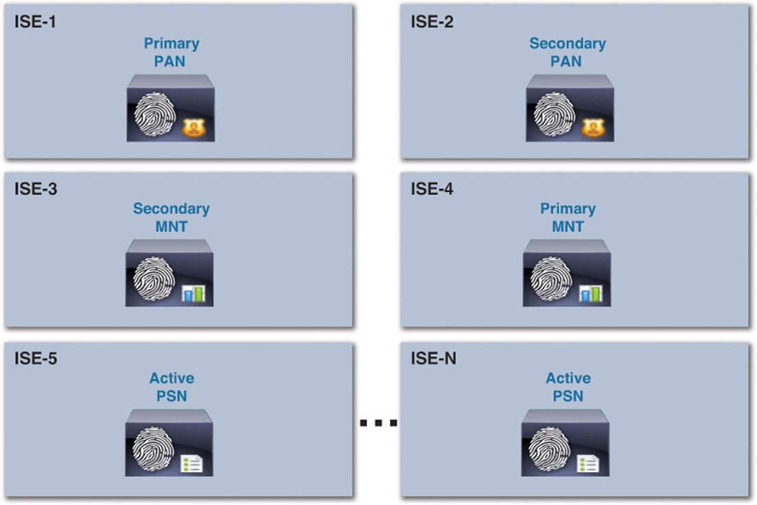
Figure 7-5 Fully distributed deployment persona assignment.
Communication Between Nodes
As mentioned previously, it is best to always deploy ISE in a redundant fashion when used in a production environment. This ensures that a single failure of ISE will not cause a permanent network outage. As you deploy the two-node, four-node, and fully distributed models as described previously, you must ensure that you allow the required communication and allocate the appropriate bandwidth between the individual nodes. If you fail to ensure proper communication between the nodes, the function and performance of the Cisco ISE ecosystem can be greatly impacted.
For all nodes, regardless of persona, it is imperative that you permit TCP/22 (SSH), TCP/80 (HTTP), and TCP/443 (HTTPS). These ports are used for administrative functions on the ISE nodes. Additionally, allowing port TCP/9060 to the PAN nodes will enable you to use the External RESTful Services (ERS) REST API.
There are also a number of ports that should be allowed for External Resources. These ports are used to allow access to LDAP (TCP/UDP/389, TCP/3268), SMB (TCP/445), NTP (UDP/123), DNS (TCP/UDP/53), and Kerberos (TCP/UDP/88 for KDC and TCP/464 for KPASS).
Additional ports are provided in Table 7-4. These enable communications amongst ISE personas and with other network resources and endpoints.
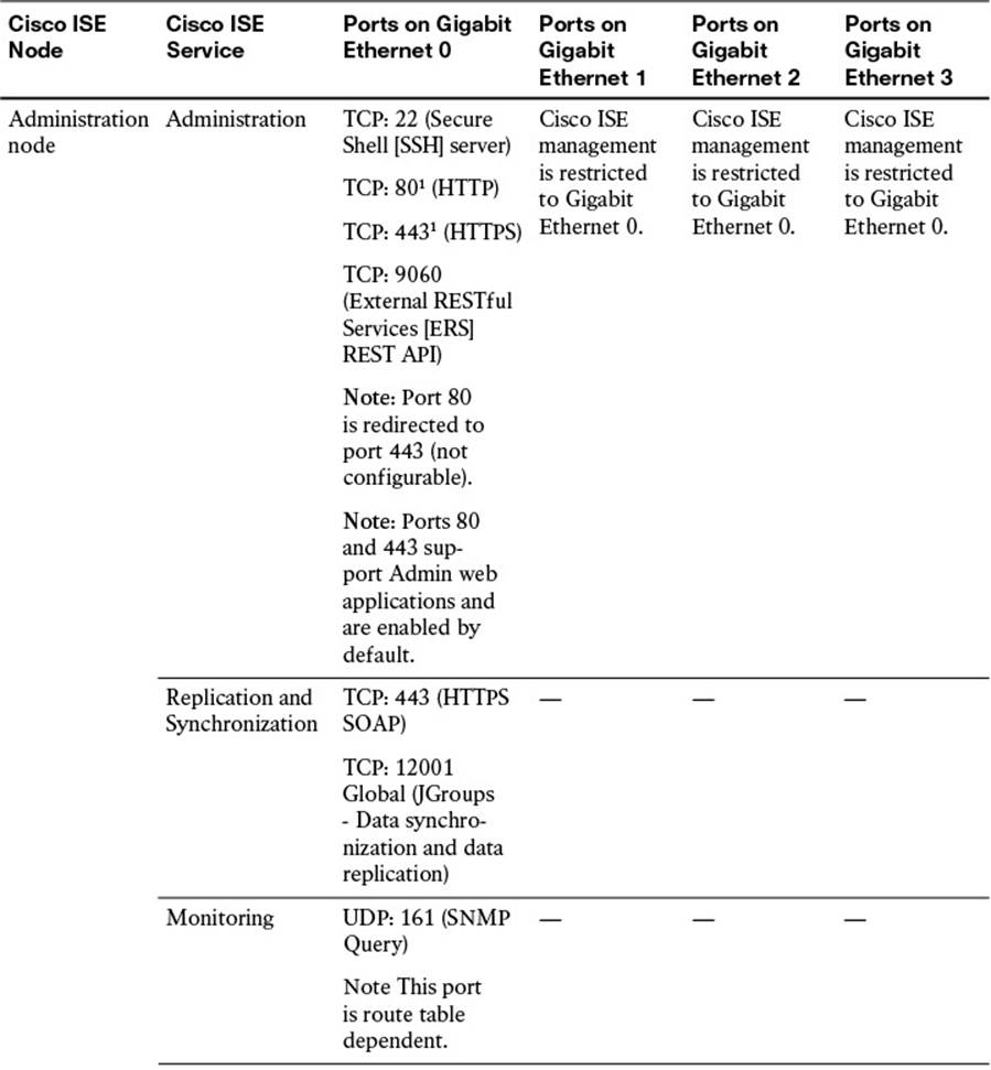
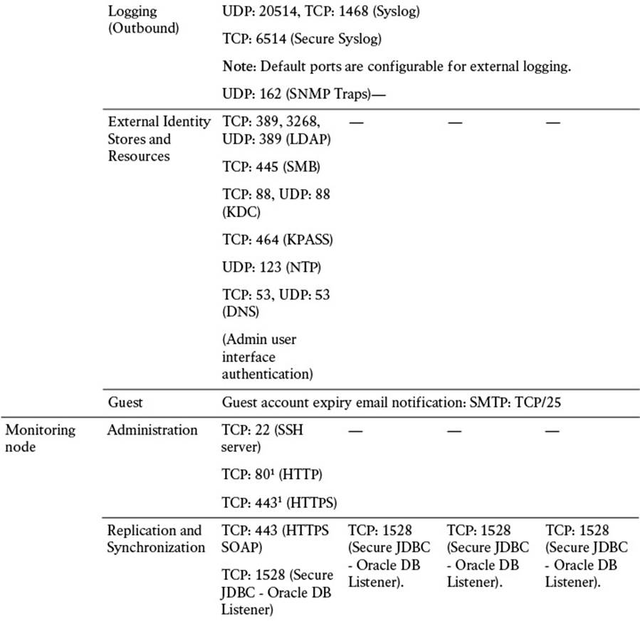
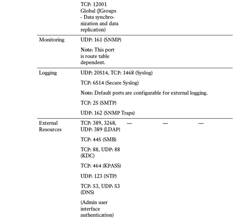
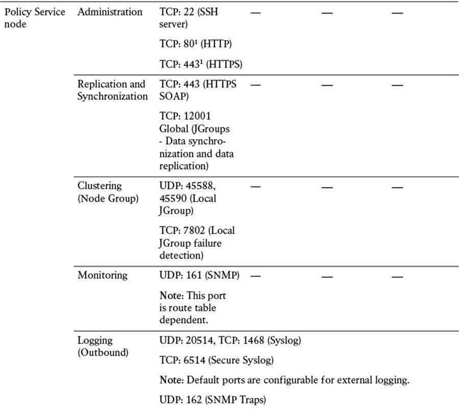
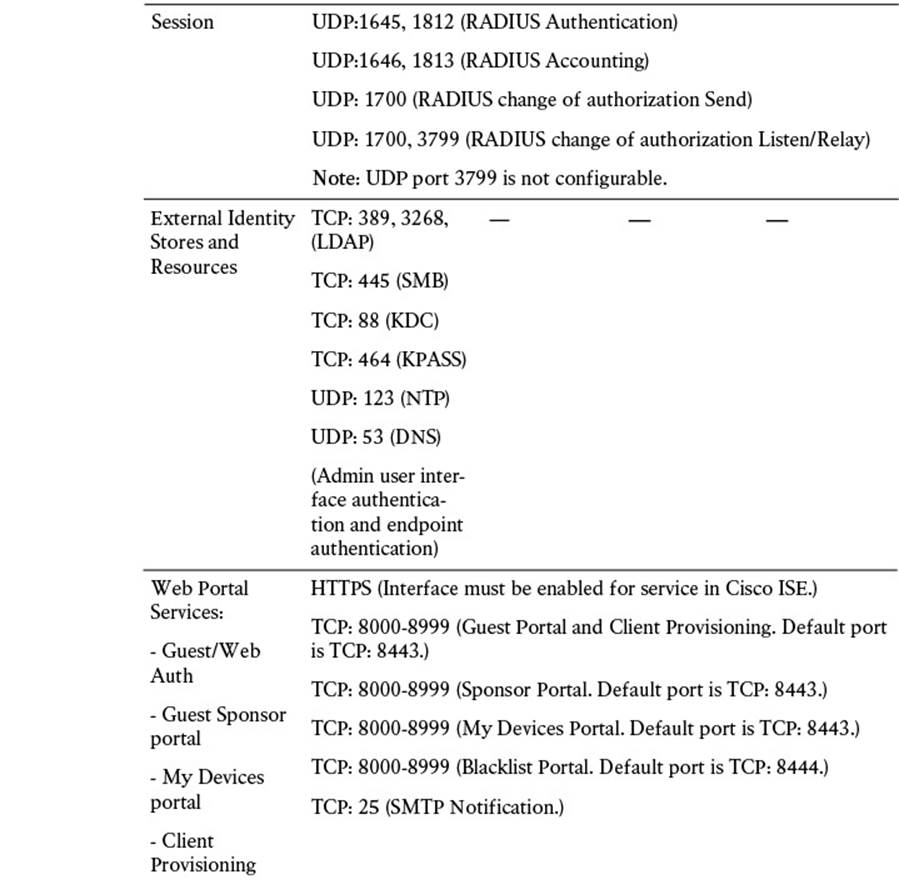
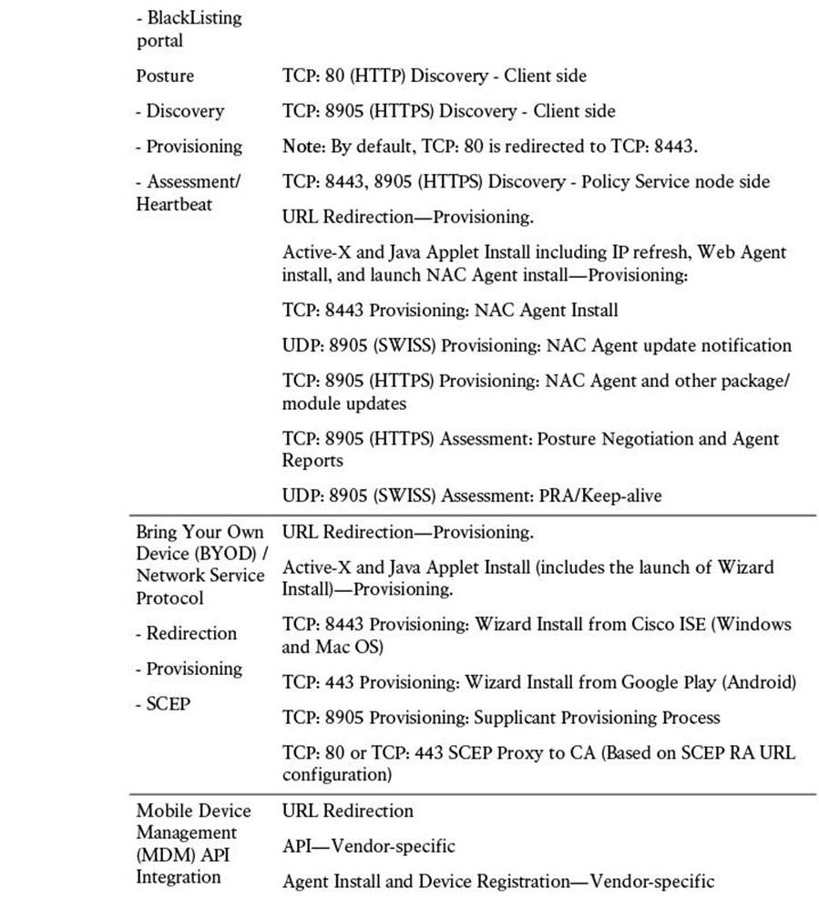
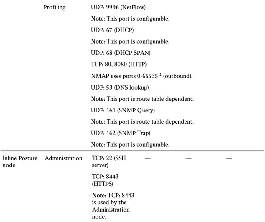
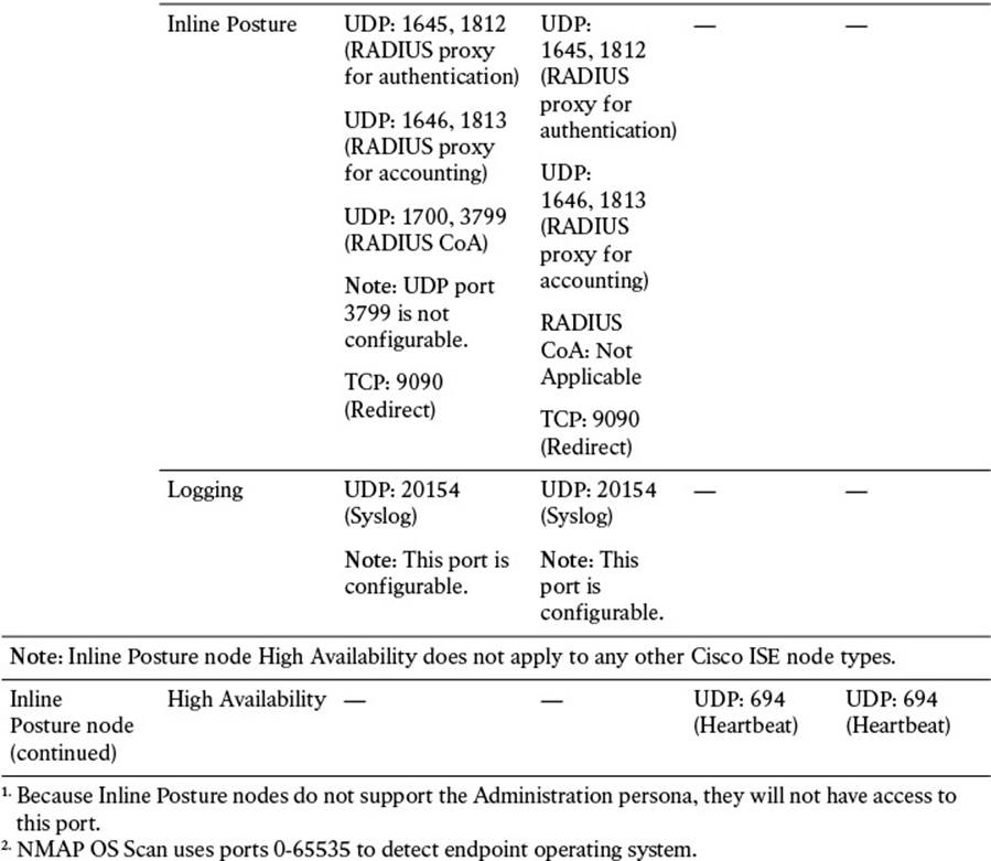
Table 7-4 Cisco ISE Services and Ports
The amount of communication exchanged between the various ISE personas and other network resources can be quite substantial, so it is critical that you allocate sufficient bandwidth across the network. LAN speed (1 Gbps) between nodes is recommended (see Table 7-5) to ensure that this communication is not interrupted. If your deployment is unable to provide this minimum bandwidth, please contact your Cisco Channel Partner or Cisco account representative for guidance.
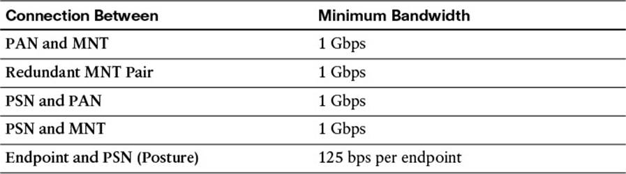
Table 7-5 Cisco ISE Bandwidth Requirements
Exam Preparation Tasks
Review All Key Topics
Review the most important topics in the chapter, noted with the key topics icon in the outer margin of the page. Table 7-6 lists a reference of these key topics and the page numbers on which each is found.

Table 7-6 Key Topics for Chapter 7
Define Key Terms
Define the following key terms from this chapter and check your answers in the glossary:
personas
Policy Admin Node (PAN)
Monitoring and Troubleshooting (MNT) Node
Policy Service Node (PSN)
Inline Posture Node
All materials on the site are licensed Creative Commons Attribution-Sharealike 3.0 Unported CC BY-SA 3.0 & GNU Free Documentation License (GFDL)
If you are the copyright holder of any material contained on our site and intend to remove it, please contact our site administrator for approval.
© 2016-2026 All site design rights belong to S.Y.A.