Implementing Cisco IOS Network Security (IINS) Foundation Learning Guide, Second Edition (2013)
Part II: Protecting the Network Infrastructure
Chapter 5. Securing the Data Plane on Cisco Catalyst Switches
In this chapter, you learn that, like routers, both Layer 2 and Layer 3 switches have their own set of network security requirements. Access to switches is a convenient entry point for attackers who are intent on illegally gaining access to a corporate network. With access to a switch, an attacker can set up rogue access points and protocol analyzers and launch all types of attacks from within the network. Attackers can even spoof the MAC and IP addresses of critical servers to do much damage. In this chapter, you will examine various Layer 2 attacks and strategies to mitigate them. Topics covered in this chapter include the following:
• An introduction to fundamental switching concepts, starting with the building blocks of VLANs and trunking
• An introduction to other building blocks of switching technology, including Spanning Tree Protocol for high availability
• A revisit and further explanation of security threats that exploit vulnerabilities in the switching infrastructure
• A description of how to plan and develop a strategy for protecting the data plane
• A description of the Spanning Tree Protocol Toolkit found on Cisco IOS routers that prevents STP operations from having an impact on the security posture
• A review of port security and how to configure it, to illustrate security controls that are aimed at mitigating MAC spoofing and other threats
Note
Prior to covering Layer 2 data plane security, this chapter includes an overview of related technologies such as VLANs, trunking, and spanning tree. For greater details on these topics, refer to the third edition of Cisco Press CCNA ICND2 640-816 Official Cert Guide.
Overview of VLANs and Trunking
A virtual LAN (VLAN) is a logical broadcast domain that can span multiple physical LAN segments. Within the switched internetwork, VLANs provide segmentation and organizational flexibility. You can design a VLAN structure that lets you group stations that are segmented logically by functions, project teams, and applications without regard to the physical location of the users, as shown in Figure 5-1. You can assign each port of a switch to only one VLAN, adding a layer of security. Ports in a single VLAN share broadcasts, while ports in different VLANs do not share broadcasts. Containing broadcasts within a VLAN improves the overall performance of the network.
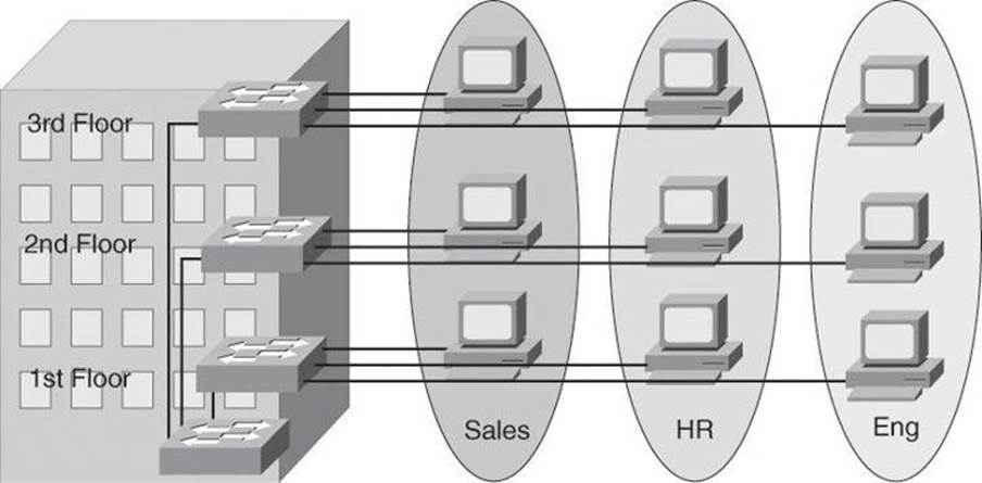
Figure 5-1. A Building LAN Segmented with VLANs
Within the switched internetwork, VLANs provide segmentation and organizational flexibility. Using VLAN technology, you can group switch ports and their connected users into logically defined communities, such as coworkers in the same department, a cross-functional product team, or diverse user groups sharing the same network application.
A VLAN can exist on a single switch or span multiple switches. VLANs can include stations in a single building or in a multiple-building infrastructure. VLANs can also connect across WANs.
A Cisco Catalyst switch operates in a network similar to a traditional bridge. Each VLAN that you configure on the switch implements address learning, forwarding and filtering decisions, and loop avoidance mechanisms as if the VLAN were a separate physical bridge.
A Cisco Catalyst switch implements VLANs by restricting traffic forwarding to destination ports that are in the same VLAN as the originating ports. So when a frame arrives on a switch port, the switch must retransmit the frame to only the ports that belong to the same VLAN. In essence, a VLAN that is operating on a switch limits transmission of unicast, multicast, and broadcast traffic. Traffic originating from a particular VLAN floods to only the other ports in that VLAN, creating a broadcast domain.
What is a VLAN? It is a single broadcast domain. It is a logical network, thus it is a subnet.

Trunking and 802.1Q
By default, a switch port carries the traffic for only a single VLAN. This is called an access port. If two interconnected switches need to exchange frames from more than one VLAN, their interconnecting ports are configured as trunks, instead of access ports. Therefore, a trunk port can carry traffic for multiple VLANs, as shown at the top of Figure 5-2.
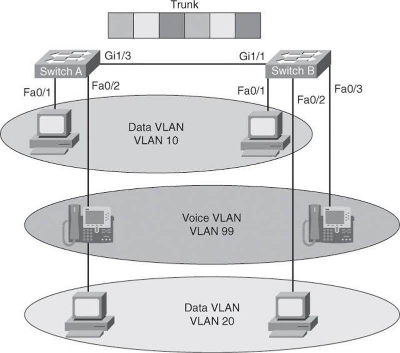
Figure 5-2. Trunk Ports Carry Traffic for Multiple VLANs
A trunk is a point-to-point link between one or more Ethernet switch interfaces and another networking device such as a router or a switch. A trunk is meant to carry the traffic of multiple VLANs over that single link and allow you to extend the VLANs across an entire network.
Trunk Versus Multi-VLAN Access Port
As just mentioned, a port that carries traffic for a single VLAN is called an access port, and a port that carries traffic for multiple VLANs s is called a trunk port. However, a clarification is needed: a trunk is a port that carries traffic for multiple data VLANs. If a port carries traffic for both a data VLAN and a voice VLAN, it is not called a trunk: it is called a multi-VLAN access port. Voice VLANs are not considered data VLANs per se. Therefore, a port carrying voice VLAN traffic and data VLAN traffic is not technically carrying traffic for two data VLANs, and thus is not a trunk.
Looking at Figure 5-2, notice that connected in port Fa0/2 of Switch A is an IP Phone, from which is hanging a PC. This IP Phone has a built-in mini switch. The IP Phone’s built-in switch, connected to port Fa0/2, passes to Switch A traffic from the PC (VLAN 20 traffic) and traffic generating by the IP Phone itself when the user places a call (VLAN 99 traffic). Port Fa0/2 on Switch A is said to be a multi-VLAN access port, and not a trunk. By comparison, port Gi1/2 on the same switch is a trunk because it is carrying traffic for more than one data VLAN: it carries traffic for data VLAN 10 and data VLAN 20, in addition to traffic for voice VLAN 99.
A trunk can be made of one or multiple interfaces combined. Interfaces belonging to a trunk require special encapsulation, which indicates the origin VLAN number of the traffic sent across the trunk. This encapsulation process will be discussed later in this section.
Cisco supports IEEE 802.1Q encapsulation. Ethernet interfaces support different trunking modes: you can configure an interface as trunking or nontrunking, or have it negotiate trunking with the neighboring interface; you can also configure which mode it will operate in and if it will be a trunk or an access port.
Besides the widely popular 802.1Q trunk encapsulation standard, Cisco has its own trunking protocol called Inter-Switch Link (ISL). However, it’s not supported by all Cisco switch models.
Interfaces configured as 802.1Q ports are assigned to a trunk. All ports on a trunk are in a native VLAN, which will be covered in more detail later in this section. Every 802.1Q port is assigned an identifier value that is based on the native VLAN ID (VID) of the port (the default is VLAN 1). All untagged frames are assigned to the VLAN specified in this VID parameter.
802.1Q Tagging
IEEE 802.1Q uses an internal tagging mechanism that inserts a 4-byte Tag field into the original Ethernet frame between the source address and type or length fields, as shown in Figure 5-3. Because 802.1Q alters the frame, the trunking device recomputes the frame check sequence (FCS) on the modified frame.
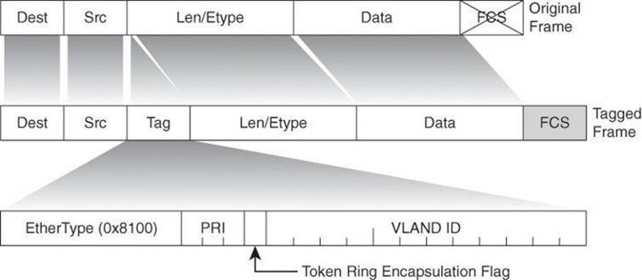
Figure 5-3. 802.1Q Frame Format
It is the responsibility of the Ethernet switch to look at the 4-byte Tag field and determine where to deliver the frame. A tiny part of the 4-byte Tag field (3 bits, to be exact) is used to specify the priority of the frame. The details of this are specified in the IEEE 802.1p standard. The 802.1Q header contains the 802.1p field, so you must have 802.1Q to have 802.1p.
Native VLANs
An 802.1Q trunk and its associated trunk ports have a native VLAN value. 802.1Q does not tag frames for the native VLAN. Therefore, ordinary stations can read the native untagged frames but cannot read any other frame because the frames are tagged.
If a switch receives an untagged frame on a trunk port, the switch will associate the frame to the native VLAN. Similarly, outgoing frames that belong to the native VLAN will not be tagged using 802.1Q.
Configuring VLANs and Trunks
There are four general tasks required to configure VLANs and trunking and provide inter-VLAN routing. You will notice in the following steps that trunk ports are configured in a single step, while access ports require the configuration of a VLAN first, and then the assignment of the VLAN to the port.
Step 1. Configure and verify 802.1Q trunks.
Step 2. Create or modify a VLAN.
Step 3. Assign switch ports to a VLAN and verify.
Step 4. Configure inter-VLAN routing
Step 1: Configuring and Verifying 802.1Q Trunks
The interface configuration command to set a Fast Ethernet or Gigabit Ethernet port to trunk mode is
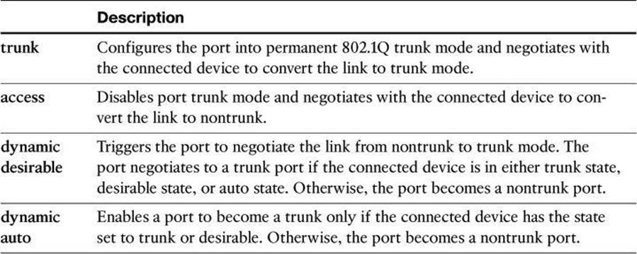
Switch(config-if)# switchport mode {access | dynamic {auto | desirable} | trunk}
Many Cisco Catalyst switches support the Dynamic Trunking Protocol (DTP), which manages automatic trunk negotiation.
Table 5-1 describes the four options for the switchport mode command.
Table 5-1. switchport mode Command Parameters
Example 5-1 shows how to configure a port as a trunk.
Example 5-1. switchport mode Command
Switch(config)# interface fa0/1
Switch(config-if)# switchport mode trunk
You have the following options to control trunking for ports:
• For links that you do not intend to trunk across, use the switchport mode access interface configuration command to disable trunking.
• For links that you do intend to trunk across, take the following actions:
• Use the switchport mode trunk interface configuration command to cause the interface to become a trunk link.
• Use the switchport nonegotiate interface configuration command to prevent the generation of Dynamic Trunking Protocol frames. This command is valid only when the interface switchport mode is access or trunk (configured by using the switchport mode access or the switchport mode trunk interface configuration command). This command returns an error if you attempt to execute it in dynamic (auto or desirable) mode. Use the no form of this command to return to the default setting. When you configure a port with theswitchport nonegotiate command, the port trunks only if the other end of the link is specifically set to trunk. The switchport nonegotiate command does not form a trunk link with ports in either dynamic desirable or dynamic auto mode.
• Use the switchport trunk native vlan vlan_number interface configuration command to set the native VLAN on the trunk to an unused VLAN. The default native VLAN is VLAN 1.
• Use the switchport trunk allowed vlan vlan_number interface configuration command to set the list of allowed VLANs that transmit traffic from this interface in tagged format when trunking mode is on.
Verifying a Trunk
To verify a trunk configuration on many Cisco Catalyst switches, use the show interfaces interface switchport command or the show interfaces interface trunk command to display the trunk parameters and VLAN information of the port:
Switch# show interfaces interface [switchport | trunk]
In the output of the show interfaces interface switchport command in Example 5-2, notice the distinction between the operational mode and administrative mode for each port. This is extremely helpful in troubleshooting trunks. The administrative mode is the configured mode, while the operational mode will depend on the results of trunk negotiations. If trunk negotiations fail, the port will be administratively configured as a trunk (as shown in Example 5-2), but the operational mode will be different. It could be down, as in Example 5-2, or even fall back to an active port on the default VLAN 1.
Example 5-2. show interfaces interface switchport Command
SwitchX# show interfaces fa0/11 switchport
Name: Fa0/11
Switchport: Enabled
Administrative Mode: trunk
Operational Mode: down
Administrative Trunking Encapsulation: dot1q
Negotiation of Trunking: On
Access Mode VLAN: 1 (default)
Trunking Native Mode VLAN: 1 (default)
In the output of the show interfaces interface trunk command in Example 5-3, you will notice in the allowed VLANs section that traffic for a particular VLAN will not traverse the trunk if the VLAN does not show in this section.
Example 5-3. show interfaces fa0/11 trunk Command
SwitchX# show interfaces fa0/11 trunk
Port Mode Encapsulation Status Native vlan
Fa0/11 desirable 802.1Q trunking 1
Port Vlans allowed on trunk
Fa0/11 1-4094
Port Vlans allowed and active in management domain
Fa0/11 1-13Trunking Native Mode VLAN: 1 (default)
Step 2: Creating a VLAN
The maximum number of VLANs that can be created is switch-dependent. However, most Cisco Catalyst desktop switches support 128 separate spanning-tree instances, one per VLAN. VLAN 1 is the factory default Ethernet VLAN. The Cisco Discovery Protocol (CDP) advertisements and other protocols are sent on VLAN 1. The Cisco Catalyst switch IP address is in the management VLAN (VLAN 1 by default) that is the IP address used to telnet, or SSH, in the switch. This management IP address is also used by the switch if it has been configured for Simple Network Management Protocol (SNMP) or syslog.
The configuration commands to create a VLAN are as follows:
Switch(config)# vlan vlan-id
Switch(config-vlan)# name vlan-name
Table 5-2 lists the commands for creating VLANs.
Table 5-2. Adding a VLAN Command
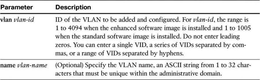
Example 5-4 shows how to create a VLAN.
Example 5-4. Example of VLAN Creation
Switch(config)# vlan 2
Switch(config-vlan)# name Marketing
Before you create VLANs, consider these guidelines:
• Most Cisco Catalyst desktop switches support a maximum of 128 spanning-tree instances. If the number of VLANs on the switch exceeds the number of supported spanning-tree instances, it is recommended that you configure Multiple Spanning Tree Protocol (MSTP) on your switch to map multiple VLANs to a single spanning-tree instance.
• The maximum number of VLANs is switch-dependent. Many access layer Cisco Catalyst switches can support up to 250 user-defined VLANs.
• Cisco Catalyst switches have a factory default configuration in which various default VLANs are preconfigured to support various media and protocol types. The default Ethernet VLAN is VLAN 1. Cisco Discovery Protocol advertisements and other protocols are sent on VLAN 1.
• For you to be able to communicate with the Cisco Catalyst switch remotely for management purposes, the switch must have an IP address. This IP address must be in a management VLAN; the default management VLAN is VLAN 1.
After you configure the VLAN, you should validate the parameters for that VLAN. Use the show vlan command to display information about a particular VLAN:
Switch# show vlan [brief | id vlan-id | name vlan-name]
Example 5-5 shows the output of the show vlan id command.
Example 5-5. Output of the show vlan id Command
SwitchX# show vlan id 2
VLAN Name Status Ports
---- -------------------- ------ ------- -------------
2 switchlab99 active Fa0/2, Fa0/12
VLAN Type SAID MTU Parent RingNo BridgeNo Stp BrdgMode Trans1 Trans2
---- ---- ------ ---- ------ ------ -------- --- -------- ------ ------
2 enet 100002 1500 - - - - - 0 0
. . .
SwitchX#
Use the show vlan brief command to display one line for each VLAN that displays the VLAN name, the status, and the switch ports.
Use the show vlan command to display information on all configured VLANs. The show vlan command displays the switch ports that are assigned to each VLAN. Other VLAN parameters that are displayed include the type (the default is Ethernet); the security association ID (SAID), used for the FDDI trunk; the maximum transmission unit (MTU) (the default is 1500 for Ethernet VLAN); the STP; and other parameters that are used for Token Ring or FDDI VLANs. (Chances are you have never heard of Token Ring or FDDI network. These were competing technologies prior to the obvious emergence of Ethernet as leader.)
Step 3: Assigning Switch Ports to a VLAN
After creating a VLAN, you can manually assign a port or a number of ports to that VLAN with the following command:
Switch(config-if)# switchport access [vlan vlan-id | dynamic]
A port can belong to only one VLAN at a time. When you assign a switch port to a VLAN using this method, as shown in Example 5-6, it is known as a static-access port.
Example 5-6. Assigning a VLAN to a Port with the switchport access Command
SwitchX(config)# interface range fastethernet 0/2 - 4
SwitchX(config-if)# switchport access vlan 2
SwitchX# show vlan
VLAN Name Status Ports
---- ----------------- --------- ----------------------
1 default active Fa0/1
2 switchlab99 active Fa0/2, Fa0/3, Fa0/4
On most Cisco Catalyst switches, you configure the VLAN port assignment from interface configuration mode using the switchport access command. Use the vlan vlan_number option to set static-access membership. The dynamic option uses the VLAN Membership Policy Server (VMPS) method and is outside of the scope of this book.
Use the show vlan brief privileged EXEC command to display the VLAN assignment and membership type for all switch ports, as shown in Example 5-7. It is worth mentioning that if a given port does not show under the Ports column of the table, it could be a trunk port carrying multiple VLANs.
Example 5-7. Verifying a VLAN Assignment with the show vlan Command
SwitchX# show vlan brief
VLAN Name Status Ports
---- ------------------- ------------ --------- ------------------
1 default active Fa0/1
2 switchlab99 active Fa0/2, Fa0/3, Fa0/4
3 vlan3 active
4 vlan4 active
1002 fddi-default act/unsup
1003 token-ring-default act/unsup
VLAN Name Status Ports
---- ------------------- ------------ -------------------------------
1004 fddinet-default act/unsup
1005 trnet-default act/unsup/4
Step 4: Configuring Inter-VLAN Routing
Inter-VLAN communication occurs between broadcast domains via a Layer 3 device. In a VLAN environment, frames are switched only between ports within the same broadcast domain. VLANs perform network partitioning and traffic separation at Layer 2. Inter-VLAN communication cannot occur without a Layer 3 device, such as a router.
One way to accomplish inter-VLAN routing is illustrated in Figure 5-4. You can use IEEE 802.1Q to enable trunking on a router interface, and enable the router to route between VLANs. This is sometimes known as a “router on a stick” scenario, where a router is attached to a core switch. The router can receive packets on one VLAN and forward them to another VLAN. To perform inter-VLAN routing functions, the router must know how to reach all VLANs being interconnected. There must be a separate connection on the router for each VLAN, and you must enable 802.lQ trunking on those connections. The router already knows about directly connected networks. The router must learn routes to networks to which it is not directly connected.
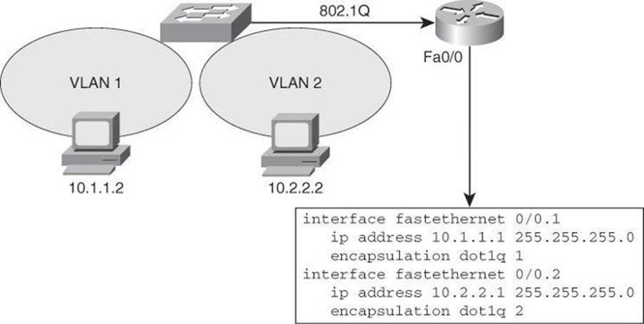
Figure 5-4. Routing Between VLANs with 802.1Q Trunks
To support 802.1Q trunking, you must subdivide the physical Fast Ethernet interface of the router into multiple, logical, addressable interfaces, one per VLAN. The resulting logical interfaces are called subinterfaces. Without this subdivision, you would have to dedicate a separate physical interface to each VLAN.
In Figure 5-4, the FastEthernet 0/0 interface is divided into two subinterfaces: FastEthernet 0/0.l and FastEthernet0/0.2. Each subinterface represents the router in each of the VLANs for which it routes. The sample configuration in Figure 5-4 uses the encapsulation dotlq vlan-id command on each subinterface to enable 802.1Q encapsulation trunking. The subinterface number does not have to be the same as the dot1q VLAN number; however, management is easier when both numbers are the same.
Note
Layer 3 switches, multilayer switches, are meant to replace the router on a stick shown in Figure 5-4 by incorporating the Layer 3 routing functionality and VLAN interfaces within the switch itself
It is also worth noting that the resulting configuration of FastEthernet0/0.1 on the router in Figure 5-4, from issuing the command encapsulation dot1q 1, would be encapsulation dot1q 1 native. The topic of native VLANs was covered earlier in the chapter.
Spanning Tree Overview
Redundant designs, such as the one shown in Figure 5-5, can mitigate the possibility of a single point of failure, which can cause a loss of function for the entire switched or bridged network.
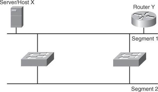
Figure 5-5. Redundant Topology
However, you must consider problems that redundant designs can cause. Some of the problems that can occur with redundant links and devices in switched or bridged networks are as follows:
• Broadcast storms: Without some loop-avoidance process in operation, each switch or bridge floods broadcasts endlessly. This situation is commonly called a broadcast storm.
• Multiple frame transmission: Multiple copies of unicast frames may be delivered to destination stations. Many protocols expect to receive only a single copy of each transmission. Multiple copies of the same frame can cause unrecoverable errors.
• MAC database instability: Instability in the content of the MAC address table results from copies of the same frame being received on different ports of the switch. Data forwarding can be impaired when the switch consumes the resources that are coping with instability in the MAC address table.
Layer 2 LAN protocols, such as Ethernet, lack a mechanism to recognize and eliminate endlessly looping frames. Some Layer 3 protocols implement a Time to Live (TTL) mechanism that limits the number of times a Layer 3 networking device can retransmit a packet. Lacking such a mechanism, Layer 2 devices continue to retransmit looping traffic indefinitely.
A loop-avoidance mechanism is required to solve each of these problems. This mechanism is the Spanning Tree Protocol (STP).
STP Fundamentals
Spanning Tree Protocol (STP) provides loop resolution by managing the physical paths to given network segments. STP allows physical path redundancy while preventing the undesirable effects of active loops in the network. STP is an IEEE committee standard defined as 802.1D.
STP behaves as follows:
• STP forces certain ports into a standby state so that they do not listen to, forward, or flood data frames, as seen in Figure 5-6, where one switch has a port in blocking mode. The overall effect is that only one active path exists to the other network segment at any time.
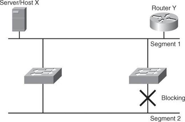
Figure 5-6. Loop Resolution with STP
• If there is a problem with connectivity to any of the segments within the network, STP reestablishes connectivity by automatically activating a previously inactive path, if one exists.
RSTP, the Rapid Spanning Tree Protocol, is a version of STP enhanced for fast convergence. RSTP is defined as the IEEE standard 802.1w.
PVST+ is a Cisco implementation of RSTP that provides enhancements that are aimed at scalability of the protocol, as well as provisions for traffic load sharing across STP-enabled paths.
STP performs three steps to provide a loop-free logical network topology, as shown in Figure 5-7:
Step 1. Selects one root bridge.
STP has a process to elect a root bridge, which will be discussed later. Only one bridge can act as the root bridge in a given network. On the root bridge, all ports are designated ports. Designated ports are normally in the forwarding state. When in the forwarding state, a port can send and receive traffic. In Figure 5-7, Switch X is the root bridge.

Figure 5-7. STP Operation and Resulting Topology
Step 2. Selects the root port on the nonroot bridge.
STP establishes one root port on each nonroot bridge. The root port is the lowest-cost path from the nonroot bridge to the root bridge. Root ports are normally in the forwarding state. Spanning-tree path cost is an accumulated cost that is calculated on the bandwidth. In Figure 5-7, the lowest-cost path to the root bridge from Switch Y is through the 100BASE-T Fast Ethernet link.
Step 3. Selects the designated port on each segment.
On each segment, STP establishes one designated port. The designated port is selected on the bridge that has the lowest-cost path to the root bridge. Designated ports are normally in the forwarding state, forwarding traffic for the segment. In Figure 5-7, the designated port for both segments is on the root bridge because the root bridge is directly connected to both segments. The 10BASE-T Ethernet port on Switch Y is a nondesignated port because there is only one designated port per segment. Nondesignated ports are normally in the blocking state to logically break the loop topology. When a port is in the blocking state, it is not forwarding traffic but can still receive traffic.
Switches and bridges running the spanning-tree algorithm exchange configuration messages with other switches and bridges at regular intervals (every 2 seconds by default). Switches and bridges exchange these messages using a multicast frame called the bridge protocol data unit (BPDU). One of the pieces of information included in the BPDU is the bridge ID (BID).
STP calls for each switch or bridge to be assigned a unique BID. Typically, the BID is composed of a priority value (2 bytes) and the bridge MAC address (6 bytes). The default priority, in accordance with IEEE 802.1D, is 32,768 (1000 0000 0000 0000 in binary, or 0x8000 in hex format), which is the midrange value. The root bridge is the bridge with the lowest BID.
Note
A Cisco Catalyst switch uses one of its MAC addresses from a pool of MAC addresses that are assigned either to the backplane or to the supervisor module, depending on the switch model.
The bridge ID (BID) is made of the bridge priority plus the bridge MAC address.
In Figure 5-8, both switches are using the same default priority. The switch with the lowest MAC address is the root bridge. In Figure 5-8, Switch X is the root bridge with the default priority of 0x8000 (hex), or 32,768 in decimal, and a MAC address of 0c00.1111.1111.
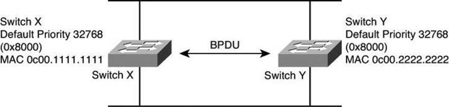
Figure 5-8. STP: Root Bridge Selection
Verifying RSTP and PVRST+
PVST is enabled by default in some Cisco Catalyst switch models. You can change the mode to Rapid PVST with the spanning-tree mode rapid-pvst command:
Switch(config)# spanning-tree mode rapid-pvst
This spanning-tree mode is the same as PVST+ except that it uses a rapid convergence that is based on the IEEE 802.1w standard.
For verification, you can use the show spanning-tree vlan vlan-range command. Example 5-8 shows the result of this command.
Example 5-8. Verifying Spanning-Tree Configuration for vlan 21
Switch# show spanning-tree vlan 21
VLAN0021
Spanning tree enabled protocol rstp
Root ID Priority 32789
Address 88f0.77c5.0f80
Cost 19
Port 1 (FastEthernet0/1)
Hello Time 2 sec Max Age 20 sec Forward Delay
15 sec
Bridge ID Priority 32789 (priority 32768 sys-id-ext 21)
Address
Hello Time d0c2.82c5.6b00
2 sec Max Age 20 sec Forward Delay
15 sec
Aging Time 300 sec
Interface Role Sts Cost Prio.Nbr Type
---------------- ---- --- --------- --------- --------------
Fa0/1 Root FWD 19 128.1 P2p
Fa0/2 Desg FWD 19 128.2 P2p
Fa0/8 Desg FWD 19 128.8 P2p
Mitigating Layer 2 Attacks
As stated at the beginning of the chapter, like routers, both Layer 2 and Layer 3 switches have their own set of network security requirements. Access to switches is a convenient entry point for attackers who are intent on illegally gaining access to a corporate network. With access to a switch, an attacker can set up rogue access points and protocol analyzers, and launch all types of attacks from within the network. Attackers can even spoof the MAC and IP addresses of critical servers to do a great deal of damage.
Basic Switch Operation
Unlike hubs, switches can regulate the flow of data between their ports by creating “instant” networks that contain only the two end devices communicating with each other at that moment in time. When end systems send data frames, their source and destination addresses are not changed throughout the switched domain. Switches maintain content-addressable memory (CAM) lookup tables to track the source MAC addresses located on the switch ports. These lookup tables are populated by an address-learning process on the switch. If the destination MAC address of a frame is not known, or if the frame received by the switch is destined for a broadcast or multicast MAC address, the switch forwards the frame to all ports. Because of their capability to isolate traffic and create instant networks, you can use switches to divide a physical network into multiple logical segments, or VLANs, using Layer 2 traffic segmenting.
Layer 2 is the data link layer in the OSI model and is one of seven layers designed to work together but with autonomy. Layer 2 operates above the physical layer, but below the network and transport layers, as shown in Figure 5-9.
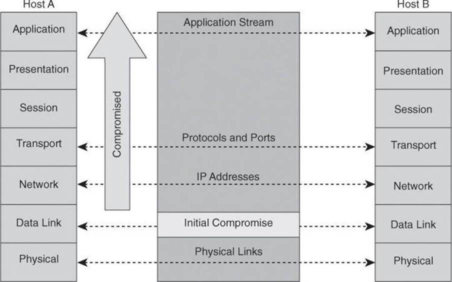
Figure 5-9. Domino Effect If Layer 2 Is Compromised
Layer 2 independence enables interoperability and interconnectivity. However, from a security perspective, Layer 2 independence creates a challenge because a compromise at one layer is not always known by the other layers. If the initial attack comes in at Layer 2, the rest of the network can be compromised in an instant. Network security is only as strong as the weakest link, and that link might be the data link layer.
Layer 2 Best Practices
The following list suggests Layer 2 security best practices. All of these suggestions are dependent upon your security policy.
• Manage switches in as secure a manner as possible (SSH, OOB, permit lists, and so on).
• Whenever practical, declare the VLAN ID used on trunk ports with the switchport trunk allowed vlan command
• Do not use VLAN 1 for anything.
• Set all user ports to nontrunking (unless you are using Cisco VoIP).
• Use port security where possible for access ports.
• Selectively use SNMP and treat community strings like root passwords.
• Enable STP attack mitigation (BPDU guard, root guard).
• Use Cisco Discovery Protocol only where necessary (with phones it is useful).
• Disable all unused ports and put them in an unused VLAN.
It is important to manage switches like routers, using secure protocols or out-of-band methods if policy permits it. Because VLAN 1 is a known management VLAN, it is recommended that you avoid using it. Turn off services that are not necessary and ports that are not being used. Implement the various security services that have been covered in this chapter as necessary and as supported by your hardware. Turn CDP off on ports that do not connect to network devices, with the exception of ports that connect to Cisco IP phones.
Layer 2 Protection Toolkit
Multiple security features and technologies are available to implement recommended practices, in a manner that streamlines configuration and management while strengthening the overall security posture. Figure 5-10 lists some of them, categorized based on type of attack (spoofing and denial of service [DoS]), type of security control (identity services and device hardening), and protocol (STP, DHCP, and Address Resolution Protocol [ARP]).
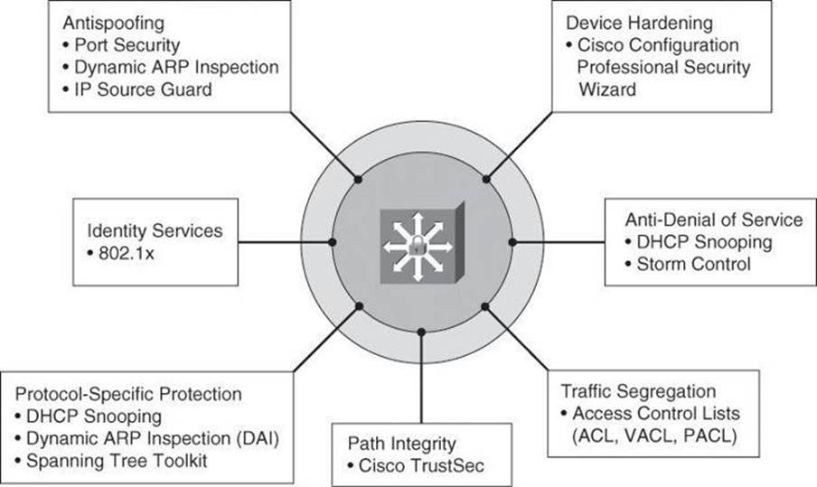
Figure 5-10. Components of Layer 2 Protection Toolkit
Some of these controls will be covered in more detail in this chapter, while some others, such as DHCP snooping and IP Source Guard, are covered in other Cisco Press books, such as CCNP Security SECURE 642-637 Official Cert Guide.
Mitigating VLAN Attacks
As mentioned at the beginning of this chapter, a VLAN is a logical broadcast domain that can span multiple physical LAN segments. Ports in a VLAN share broadcasts; ports in different VLANs do not share broadcasts. Containing broadcasts within a VLAN improves the overall performance of the network.
VLAN Hopping
The VLAN architecture simplifies network maintenance and improves performance. However, VLAN operation opens the door to abuse. VLAN hopping allows traffic from one VLAN to be seen by another VLAN without first crossing a router. Under certain circumstances, attackers can sniff data and extract passwords and other sensitive information at will. The attack works by taking advantage of an incorrectly configured trunk port. By default, trunk ports have access to all VLANs and pass traffic for multiple VLANs across the same physical link, generally between switches. The data moving across these links may be encapsulated with IEEE 802.1Q or ISL.
VLAN Hopping by Rogue Trunk
In a basic VLAN hopping attack, the attacker takes advantage of the default automatic trunking configuration on most switches. The network attacker configures a system to spoof itself as a switch. This spoofing requires that the network attacker be capable of emulating either ISL or 802.1Q signaling along with Dynamic Trunking Protocol (DTP) signaling, as shown in Figure 5-11. By tricking a switch into thinking it is another switch that needs to trunk, an attacker can gain access to all the VLANs allowed on the trunk port. To succeed, this attack requires a configuration on the port that supports trunking, such as auto. As a result, the attacker is a member of all the VLANS that are trunked on the switch and can “hop” (that is, send and receive traffic) on all of those VLANs.
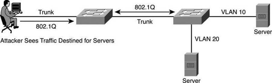
Figure 5-11. VLAN Hopping by Rogue Trunk
A VLAN hopping attack can be launched in one of two ways:
• Spoofing DTP messages from the attacking host to cause the switch to enter trunking mode: From here, the attacker can send traffic tagged with the target VLAN, and the switch then delivers the packets to the destination.
• Introducing a rogue switch and turning trunking on: The attacker can then access all the VLANs on the victim switch from the rogue switch.
The best way to prevent a basic VLAN hopping attack is to turn off trunking on all ports except the ones that specifically require trunking. On the required trunking ports, disable DTP (auto-trunking) negotiations and manually enable trunking.
VLAN Hopping by Double Tagging
The double-tagging (or double-encapsulated) VLAN hopping attack takes advantage of the way that hardware on most switches operates. Most switches perform only one level of 802.1Q decapsulation and allow an attacker, in specific situations, to embed a hidden 802.1Q tag inside the frame. This tag allows the frame to go to a VLAN that the outer 802.1Q tag did not specify. An important characteristic of the double-encapsulated VLAN hopping attack is that it works even if trunk ports are set to off.
A double-tagging VLAN hopping attack follows four steps, as shown in Figure 5-12:
Step 1. The attacker sends a double-tagged 802.1Q frame to the switch. The outer header has the VLAN tag of the attacker, which is the same as the native VLAN of the trunk port. For the purposes of this example, assume that this is VLAN 10. The inner tag is the victim VLAN, VLAN 20.
Step 2. The frame arrives on the switch, which looks at the first 4-byte 802.1Q tag. The switch sees that the frame is destined for VLAN 10 and sends it out all VLAN 10 ports (including the trunk), because there is no CAM table entry. The switch does not add a VLAN 10 tag to the frames because VLAN 10 is the native VLAN, and as specified by the 802.1Q specification, native VLAN traffic is not tagged. At this point, the second VLAN tag is still intact and has not been inspected by the first switch.
Step 3. The frame arrives at the second switch but has no knowledge that it was supposed to be for VLAN 10.
Step 4. The second switch looks only at the 802.1Q tag (the former inner tag that the attacker sent) and sees that the frame is destined for VLAN 20 (the victim VLAN). The second switch sends the packet on to the victim port, or floods it, depending on whether there is an existing CAM table entry for the victim host.
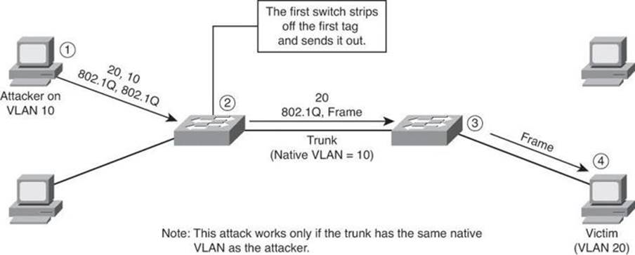
Figure 5-12. VLAN Hopping by Double Tagging
It is important to note that this attack, as shown in Figure 5-12, is unidirectional and works only when the attacker and trunk port have the same native VLAN. Thwarting this type of attack is not as easy as stopping basic VLAN hopping attacks. The best approach is to ensure that the native VLAN of the trunk ports is different from the native VLAN of the user ports.
To prevent a VLAN hopping attack that uses double 802.1Q encapsulation, the switch must look further into the packet to determine whether more than one VLAN tag is attached to a given frame. Unfortunately, the application-specific integrated circuits (ASIC) that most switches use are only hardware optimized to look for one tag and then switch the frame. The issue of performance versus security requires administrators to balance their requirements carefully.
Mitigating VLAN hopping attacks that use double 802.1Q encapsulation requires several modifications to the VLAN configuration. One of the more important elements is to use a dedicated native VLAN for all trunk ports. This attack is easy to stop if you follow the best practice that native VLANs for trunk ports should never be used anywhere else on the switch. Also, disable all unused switch ports and place them in an unused VLAN.
Mitigating Spanning Tree Attacks
Figure 5-13 shows how a network attacker can use STP to change the topology of a network so that it appears that the network attacker host is a root bridge with a higher priority. The attacker sends out BPDUs with a better bridge ID and, as a result, becomes the root bridge. Now all the traffic for this switch domain passes through the new root bridge, which is actually the attacker system.
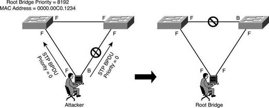
Figure 5-13. STP Manipulation
By manipulating the STP root bridge parameters, network attackers hope to spoof their system, or a rogue switch that they add to the network, as the root bridge in the topology. To do this, the network attacker broadcasts STP configuration and topology change BPDUs in an attempt to force spanning-tree recalculations. The BPDUs sent out by the system or switch of the network attacker announce that the attacking system has a lower bridge priority. If successful, the network attacker becomes the root bridge and sees a variety of frames that otherwise would not be seen.
Note
This attack can be used against all three security objectives of confidentiality, integrity, and availability.
PortFast
The spanning-tree PortFast feature causes an interface configured as a Layer 2 access port to transition from the blocking state to the forwarding state immediately, bypassing the listening and learning states. You can use PortFast on Layer 2 access ports that connect to a single workstation or server, as shown in Figure 5-14, to allow those devices to connect to the network immediately, instead of waiting for spanning tree to converge.
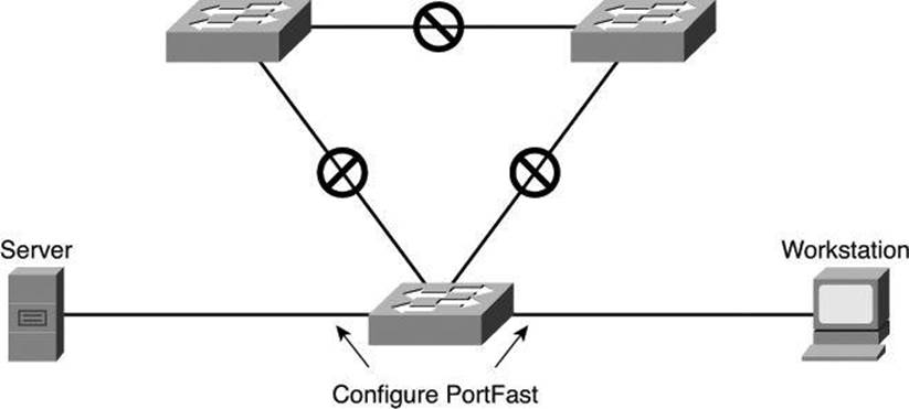
Figure 5-14. Using PortFast
If a port that is configured with PortFast receives a BPDU, STP can put the port into the blocking state by using a feature called BPDU guard.
Caution
Because the purpose of PortFast is to minimize the time that access ports must wait for spanning tree to converge, it should be used only on access ports. If you enable PortFast on a port connecting to another switch, you risk creating a spanning-tree loop.
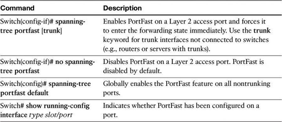
Table 5-3 lists and describes the commands that you use to implement and verify PortFast on an interface.
Table 5-3. PortFast Commands
BPDU Guard
To mitigate STP manipulation, use the BPDU guard and root guard enhancement commands available on Cisco switches to enforce the placement of the root bridge in the network and enforce the STP domain borders.
The STP BPDU guard feature is designed to enable network designers to keep the active network topology predictable. BPDU guard is used to protect the switched network from the problems that may be caused by the receipt of BPDUs on ports that should not be receiving them. The receipt of unexpected BPDUs might be accidental or might be part of an unauthorized attempt to add a switch to the network.
BPDU guard is best deployed toward user-facing ports to prevent rogue switch network extensions by an attacker.
The global command to activate BPDU guard on all ports with PortFast enabled is as follows:
Switch(config)# spanning-tree portfast bpduguard default
In Figure 5-15, the attacker starts sending out spoofed BPDUs in an effort to become the root bridge. Upon receipt of a BPDU, the BPDU guard feature disables the port.
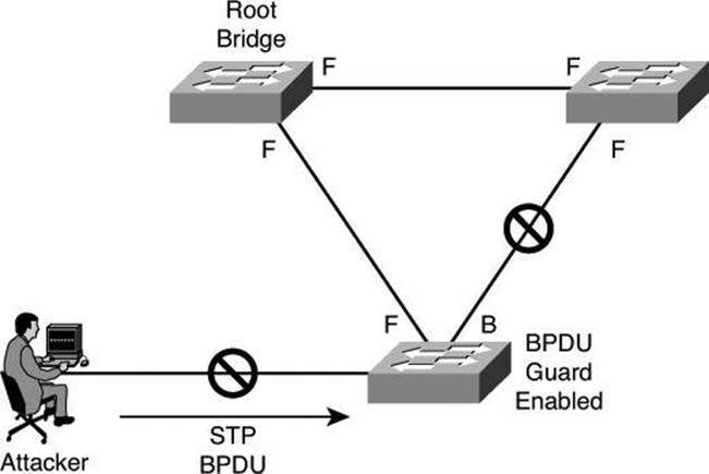
Figure 5-15. BPDU Guard
BPDU Filters
Another command used to prevent BPDU filtering, which prevents a port from sending and receiving BPDUs, is the following the interface command:
Switch(config-if)# spanning-tree bpdufilter enable
Be careful when you enter this command because it overrides the PortFast configuration, explained previously.
This command has three states:
Switch(config-if)# spanning-tree bpdufilter enable
This command state unconditionally enables BPDU filtering on the interface.
Switch(config-if)# spanning-tree bpdufilter disable
This command state unconditionally disables BPDU filtering on the interface.
Switch(config-if)# no spanning-tree bpdufilter
This command state enables BPDU filtering on the interface if the interface is in operational PortFast state and if you configure the spanning-tree portfast bpdufilter default command.
Applying BPDU Guard Globally Versus Per Port
At the global level, you can enable BPDU guard on PortFast-enabled ports by using the spanning-tree portfast bpduguard default global configuration command. In a valid configuration, PortFast-enabled ports do not receive BPDUs. Receiving a BPDU on a PortFast-enabled port signals an invalid configuration, such as the connection of an unauthorized device, and the BPDU guard feature puts the port into the error-disabled state.
At the interface level, you can enable BPDU guard on any port by using the spanning-tree bpduguard enable interface configuration command without also enabling the PortFast feature. When the port receives a BPDU, it is put into the error-disabled state.
Root Guard
The root guard feature of Cisco switches is designed to provide a way to enforce the placement of root bridges in the network. Root guard limits the switch ports out of which the root bridge can be negotiated. Root guard is configured on a per-port basis. If a root guard–enabled port receives BPDUs that are superior to those that the current root bridge is sending, that port is moved to a root-inconsistent state, which is effectively equal to an STP listening state, and no data traffic is forwarded across that port. When the port stops receiving superior BPDUs, it will be unblocked again and will transition through STP states like any other port.
Because an administrator can manually set the bridge priority of a switch to zero, root guard might seem unnecessary. However, setting the priority of a switch to zero does not guarantee that switch will be elected as the root bridge, because another switch could have a priority of zero and a lower MAC address, and therefore a lower BID.
Root guard is best deployed toward ports that connect to switches that should not be the root bridge.
Recovery requires no intervention. A root guard port is in an STP-designated port state. When root guard is enabled on a port, the switch does not allow that port to become an STP root port. The port remains an STP-designated port.
The command to enable root guard on a per-interface basis is as follows:
Switch(config-if)# spanning-tree guard root
In Figure 5-16, the attacker starts sending out spoofed BPDUs in an effort to become the root bridge. Upon receipt of a BPDU, the switch with the root guard feature configured on that port ignores the BPDU and puts the port in a root-inconsistent state. The port will recover as soon as the offending BPDUs cease.
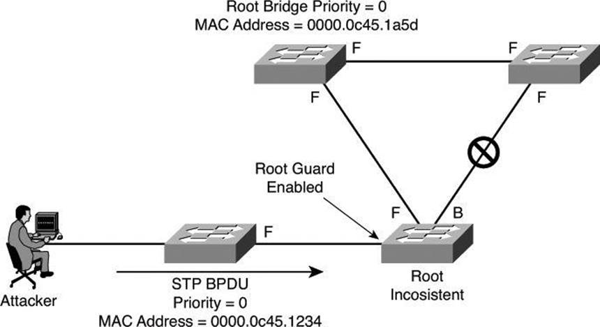
Figure 5-16. Root Guard
Confirming Spanning-Tree State and BPDU Guard
To display information about the state of spanning tree and BPDU guard, use the show spanning-tree summary command, as shown in Example 5-9.
Example 5-9. Status of BPDU Guard with the show spanning-tree summary Command
Switch# show spanning-tree summary
Root bridge for: Bridge group 1, VLAN0001, VLAN0004-VLAN1005
VLAN1013-VLAN1499, VLAN2001-VLAN4094
EtherChannel misconfiguration guard is enabled
Extended system ID is enabled
Portfast is enabled by default
PortFast BPDU Guard is enabled
Portfast BPDU Filter is disabled by default
Loopguard is disabled by default
UplinkFast is disabled
BackboneFast is disabled
Pathcost method used is long
<output omitted>
Switch#
Mitigating CAM Table Overflow Attacks
The CAM table in a switch contains the MAC addresses that can be reached off a given physical port of a switch and the associated VLAN parameters for each. When a Layer 2 switch receives a frame, the switch first populates its CAM table by creating an entry listing the source MAC address of the frame it just received and the port it was received on. This entry has an idle timeout of 5 minutes; that is, if after 5 minutes no frames have been received from that MAC address on that port, the entry will be flushed out of the CAM table.
Once the switch has populated the CAM table with the source address information, it looks in the CAM table for the destination MAC address. If an entry exists for the MAC address in the CAM table, the switch forwards the frame to the MAC address port designated in the CAM table. If the MAC address does not exist in the CAM table, the switch acts like a hub and forwards the frame out every port on the switch.
The key to understanding how CAM table overflow attacks work is to know that CAM tables are limited in size. MAC flooding takes advantage of this limitation by bombarding the switch with fake source MAC addresses until the switch CAM table is full. If enough entries are entered into the CAM table before other entries are expired, the CAM table fills up to the point that no new entries can be accepted.
In a CAM table overflow attack, a network intruder floods the switch with a large number of invalid source MAC addresses until the CAM table fills up. When that occurs, the switch begins to flood all incoming traffic to all ports because there is no room in the CAM table to learn any legitimate MAC addresses. The switch, in essence, acts like a hub. As a result, the attacker can see all the frames sent from a victim host to another host without a CAM table entry. CAM table overflow floods traffic only within the local VLAN so that the intruder will see only traffic within the local VLAN to which the intruder is connected. If the intruder does not maintain the flood of invalid source MAC addresses, the switch eventually ages out older MAC address entries from the CAM table and begins to act like a switch again.
In Figure 5-17, the macof program is running on Host C. This tool floods a switch with packets that contain randomly generated source and destination MAC and IP addresses. Over a short period, the CAM table in the switch fills up until it cannot accept new entries. When the CAM table fills up, the switch begins to flood all frames that it receives.
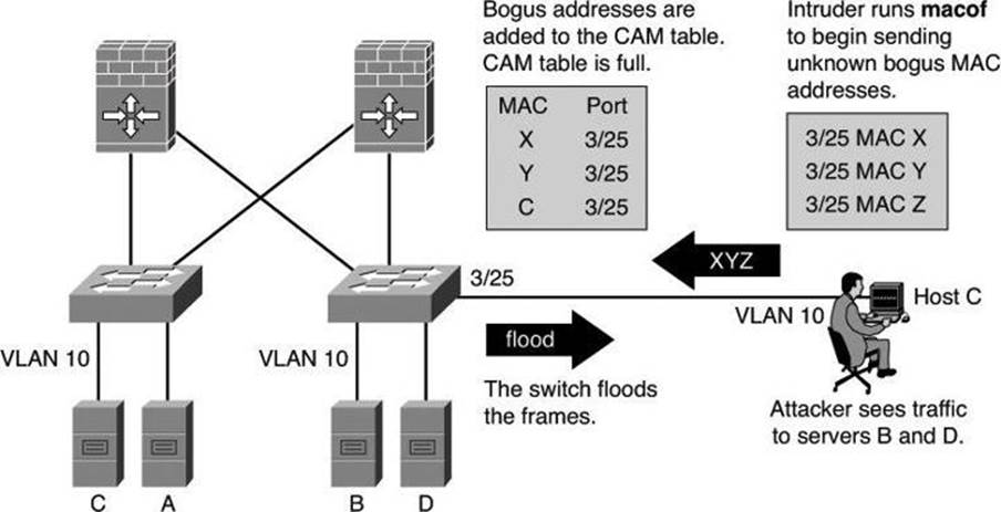
Figure 5-17. CAM Table Overflow Attack
As long as macof is left running, the CAM table on the switch remains full. When this happens, the switch begins to flood all received frames out every port so that frames sent from any host are also flooded out of port 3/25 on the switch.
The CAM table overflow attack can be mitigated by configuring port security on the switch. With port security (discussed later in this chapter), you can either statically specify the MAC addresses on a particular switch port or allow the switch to dynamically learn a fixed number of MAC addresses for a switch port. Statically specifying the MAC addresses on switch ports is far too unmanageable a solution for a production environment; allowing the switch to dynamically learn a fixed number of MAC addresses for a port is a more administratively scalable solution.
Mitigating MAC Address Spoofing Attacks
MAC spoofing attacks involve the use of a known MAC address of another host to attempt to make the target switch forward frames destined for the remote host to the network attacker. By sending a single frame with the source Ethernet address of the other host, the network attacker overwrites the CAM table entry so that the switch forwards packets destined for the host to the network attacker instead. Until the host sends traffic, it does not receive any traffic. When the host sends out traffic, the CAM table entry is rewritten once more so that it moves back to the original port.
Figure 5-18 shows how MAC spoofing works. In the beginning, the switch has learned that Host A is on port 1, Host B is on port 2, and Host C is on port 3. Host B (attacker) sends out a packet identifying itself with the source MAC address of Host A. This traffic causes the switch to move the location of Host A in its CAM table from Port 1 to Port 2. Traffic from Host C destined to Host A is now visible to Host B and not to Host A.
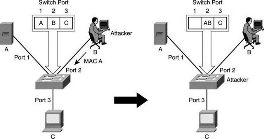
Figure 5-18. MAC Address Spoofing Attack
This attack can also be mitigated by using port security.
Using Port Security
You can use the port security feature to restrict input to an interface by limiting and identifying the MAC addresses of the stations that are allowed to access the port. When you assign MAC addresses to a secure port, the port does not forward packets with source addresses outside the group of defined addresses.
Port security allows you to statically specify MAC addresses for a port or permit the switch to dynamically learn a limited number of MAC addresses. By limiting the number of permitted MAC addresses on a port to one, you can use port security to control unauthorized expansion of the network.
When a secure port receives a packet, the source MAC address of the packet is compared to the list of secure source addresses that were manually configured or autoconfigured (learned) on the port. If a MAC address of a device attached to the port differs from the list of secure addresses, either the port shuts down until it is administratively enabled (default mode) or the port drops incoming packets from the unsecure host. The behavior of the port depends on how you configure it to respond to a security violation. In Figure 5-19, traffic from Attacker 1 and Attacker 2 will be dropped at the switch because the source MAC addresses of these frames do not match MAC addresses in the list of secured (allowed) addresses.

Figure 5-19. Port Security
It is recommended that you configure the port security feature to shut down a port instead of just dropping packets from insecure hosts. If port security does not shut down a port, it is possible that there will be too much load from an attack, and the port will be disabled anyway.
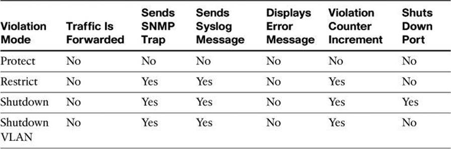
Table 5-4 summarizes the effect of each violation mode. The parameters used to configure these violation modes will be presented later in this chapter.
Table 5-4. Configurable Port Security Violation Modes
Tip
Port security protects against too many MAC addresses per port and can dictate which MAC address is allowed to connect against which port. However, if the hacker spoofs the MAC address permitted on that port, he will gain access to the network. If you are concerned by spoofed MAC addresses, then consider implementing an 802.1X authentication solution.
Errdisable Recovery
The errdisable recovery feature also allows you to monitor spanning tree violations. If enabled with the errdisable recovery command, this feature monitors ports in configurable intervals to determine their stance in terms of these violations. The feature actually tries to recover the operational status of the ports when it finds them to be in violation of the policy, making the process automatic and the recovery automated. If you do not enable the recovery for the cause, the port stays in the error-disabled state until you enter the shutdown and no shutdown interface configuration commands. If you enable the recovery for a cause, the port is brought out of the error-disabled state and allowed to retry the operation when all the causes have timed out.
Example 5-10 illustrates the syslog message that is generated upon a security violation. In this example, port Gi4/1 has been disabled due to a violation of the BPDU guard feature. The show interfaces status command displays the err-disabled status for the port.
Example 5-10. Verifying the Port Status with the show interfaces interface status Command
switch# show interfaces gigabitethernet 4/1 status
Port Name Status Vlan Duplex Speed Type
Gi4/1 err-disabled 100 full 1000 1000BaseSX
If errdisable recovery monitoring is enabled, you can see more detailed information as to the monitored features using the show errdisable recovery command, as shown in Example 5-11. There, the BPDU guard feature is being monitored every 300 seconds, and one port, Gi4/1, is error-disabled for another 290 seconds (unless you use the shutdown/no shutdown commands to enable it and no further violations occur). The 300 seconds is a configurable option.
Example 5-11. show errdisable recovery Command Output
switch# show errdisable recovery
ErrDisable Reason Timer Status
----------------- --------------
Udld Disabled
Bpduguard Enabled
security-violatio Disabled
channel-misconfig Disabled
<output omitted>
Timer interval: 300 seconds
Interfaces that will be enabled at the next timeout:
Interface Errdisable reason Time left(sec)
--------- --------------------- --------------
Gi4/1 bpduguard 290
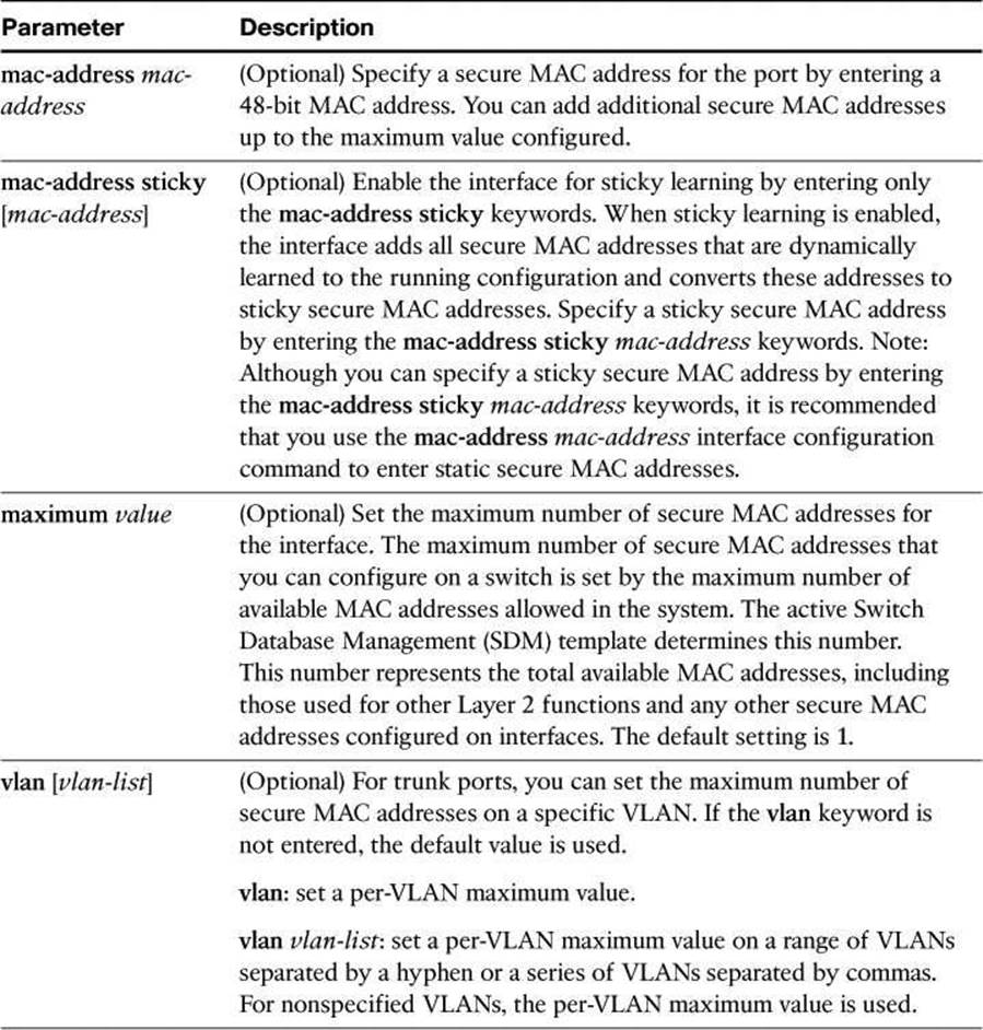
To configure port security on an access port, follow these steps (see Table 5-5 for command details).
Table 5-5. switchport port-security Command Parameters
Step 1. Enter interface configuration mode:
Switch(config)# interface FastEthernet 0/8
Step 2. Configure the interface as an access interface:
Switch(config-if)# switchport mode access
Note
An interface in the default mode (dynamic desirable) cannot be configured as a secure port.
Step 3. Enable port security on the interface:
Switch(config-if)# switchport port-security [mac-address mac-address
[vlan {vlan-id | {access | voice} } ] ] | [mac-address sticky
[mac-address| vlan {vlan-id | {access | voice} } ]] [maximum value
[vlan {vlan-list | {access | voice} } ]]
Step 4. (Optional) Set the maximum number of secure MAC addresses for the interface:
Switch(config-if)# switchport port-security maximum value
Note
The range is 1 to 132; the default is 1.
Step 5. (Optional) Set the violation mode. This is the action to be taken when a security violation is detected:
Switch(config-if)# switchport port-security violation {protect |
restrict | shutdown | shutdown vlan}
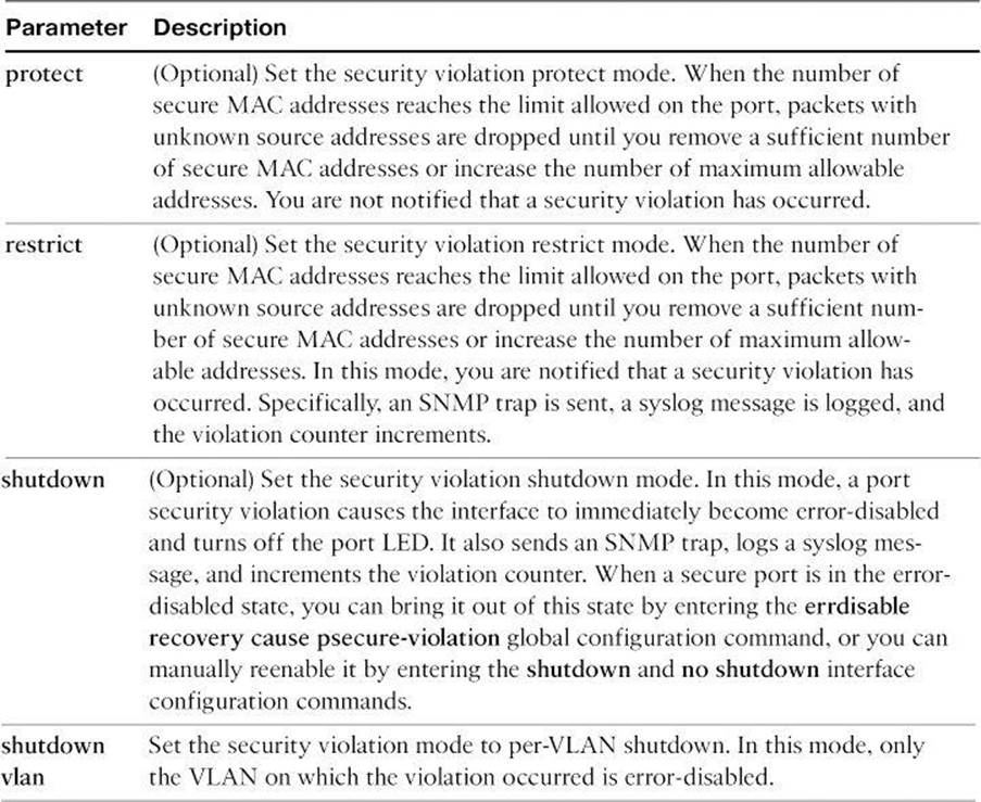
Table 5-6 provides the details of the switchport port-security violation command parameters.
Table 5-6. switchport port-security violation Parameters
Tip
When a secure port is in the error-disabled state, you can bring it out of this state by entering the errdisable recovery cause secure-violation global configuration command, or you can manually reenable it by entering the shutdown and no shutdown interface configuration commands.
Step 6. (Optional) Enter a static secure MAC address for the interface with this command:
Switch(config-if)# switchport port-security mac-address mac-address
Note
Repeat this command as many times as necessary for each secure MAC address.
Step 7. (Optional) Enable sticky learning on the interface with this command:
Switch(config-if)# switchport port-security mac-address sticky
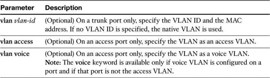
In addition to port security, consider the commands shown in Table 5-7 for making the port more secure.
Table 5-7. switchport Command Parameters
Use the no switchport port-security interface configuration command to return the interface to the default condition of not being a secure port. The sticky secure addresses remain part of the running configuration. To remove the sticky secure addresses from the running configuration, use the no mac-address mac-address command.
Use the no switchport port-security maximum value interface configuration command to return the interface to the default number of secure MAC addresses.
Use the no switchport port-security violation {protect | restrict} interface configuration command to return the violation mode to the default condition (shutdown mode).
You can use port security aging to set the aging time for static and dynamic secure addresses on a port. Each port supports two types of aging:
• Absolute: The secure addresses on the port are deleted after the specified aging time.
• Inactivity: The secure addresses on the port are deleted only if the secure addresses are inactive for the specified aging time.
You can use this feature to remove and add secure MAC addresses on a secure port without manually deleting the existing secure MAC addresses and still limit the number of secure addresses on a port. Also, you can enable or disable the aging of statically configured secure addresses on a per-port basis.
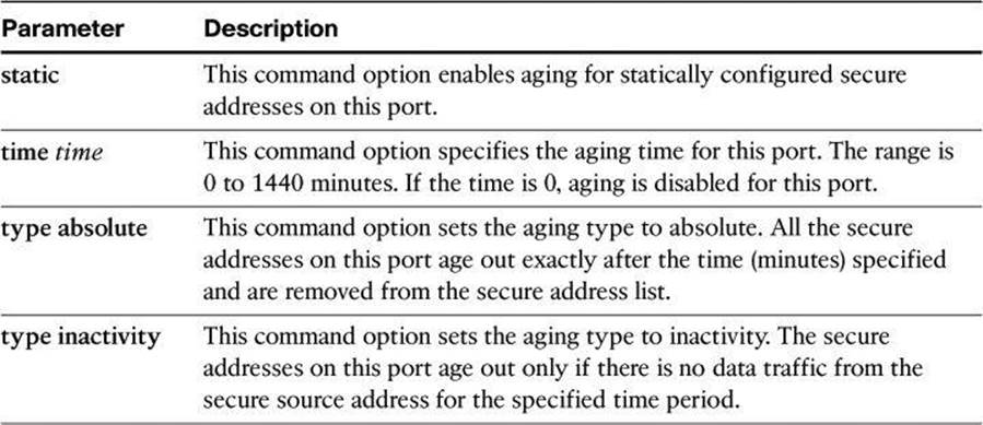
Use the switchport port-security aging {static | time time | type {absolute | inactivity} } command to enable or disable static aging for the secure port, or set the aging time or type. Table 5-8 provides the details of the switchport port-security aging parameters.
Table 5-8. switchport port-security aging Parameters
Example 5-12 shows a typical port security configuration for a voice port. Two MAC addresses are allowed, and they are to be learned dynamically. One MAC address is for the IP phone, and the other IP address is for the PC connected to the IP phone. Violations of this policy result in the port being shut down, and the aging timeout for the learned MAC addresses is set to two hours.
Example 5-12. Port Security Configuration
Switch(config-if)# switchport mode access
Switch(config-if)# switchport port-security
Switch(config-if)# switchport port-security maximum 2
Switch(config-if)# switchport port-security violation shutdown
Switch(config-if)# switchport port-security mac-address sticky
Switch(config-if)# switchport port-security aging time 120
Use the show port-security command to view port security settings for the switch, including violation count, configured interfaces, and security violation actions.
Use the show port-security [interface interface-id] command to view port security settings for the specified interface, including the maximum allowed number of secure MAC addresses for each interface, the number of secure MAC addresses on the interface, the number of security violations that have occurred, and the violation mode.
Example 5-13 shows that port security is enabled on port Fa0/12 with a maximum MAC address count of 2. Currently, there are no MAC addresses learned on that port, and the violation action has been set to shut down the port.
Example 5-13. show port-security Command Output
sw-class# show port-security
Secure Port MaxSecureAddr CurrentAddr SecurityViolation Security Action
(Count) (Count) (Count)
-------------------------------------------------------------------------------
Fa0/12 2 0 0 Shutdown
-------------------------------------------------------------------------------
Total Addresses in System (excluding one mac per port) : 0
Max Addresses limit in System (excluding one mac per port) : 1024
Example 5-14 demonstrates output from the show port-security interface fa0/12 command, revealing that a violation has occurred, which means that more than one MAC address has been seen on the port. The port has been shut down because of this policy violation, as confirmed by the secure-down port status.
Example 5-14. show port-security interface fa0/12 Command Output
sw-class# show port-security interface fa0/12
Port Security : Enabled
Port status : Secure-down
Violation mode : Shutdown
Maximum MAC Addresses : 1
Total MAC Addresses : 2
Configured MAC Addresses : 0
Aging time : 120 mins
Aging type : Absolute
SecureStatic address aging : Disabled
Security Violation Count : 1
Use the show port-security [interface interface-id] address command to view all the secure MAC addresses that are configured on all switch interfaces, or on a specified interface, with aging information for each address.
Example 5-15 shows that port Fa0/12 is in VLAN 1 and has a secured MAC address of 0000.ffff.aaaa, which means that the host with the 0000.ffff aaaa MAC address can connect to port Fa0/12.
Example 5-15. show port-security address Command Output
sw-class# show port-security address
Secure Mac Address Table
----------------------------------------------------
Vlan Mac Address Type Ports Remaining Age
(mins)
---- ----------- ---- ----- -------------
1 0000. ffff. aaaa SecureConfigured Fa0/12 -
----------------------------------------------------
Total Addresses in System (excluding one mac per port) : 0
Max Addresses limit in System (excluding one mac per port) : 1024
Using SNMP to Monitor Access to Switch Port
Network managers need a way to monitor who is using the network and where they are. In Figure 5-20, if port Fa2/1 is secure, an SNMP trap will be generated when MAC D disappears from the CAM table of the switch.
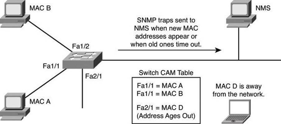
Figure 5-20. Notification of Intrusions
The MAC address notification feature sends SNMP traps to the network management station (NMS) whenever a new MAC address is added to, or an old address is deleted from, the forwarding tables. MAC notifications are generated only for dynamic and secure MAC addresses.
MAC address notification allows the network administrator to monitor MAC addresses that are learned and MAC addresses that age out and are removed from the switch.
Use the mac address-table notification change global configuration command to enable the MAC address notification feature on the switch.
Summary
Layer 2 security is often an overlooked aspect of network security. Buffer overflows can be the worst of these problems. The goals of endpoint security include protection from viruses, worms, and Trojan horses. SAN and voice security are also increasingly important because these technologies are growing in popularity in the modern enterprise.
The major points that were covered in this chapter are as follows:
• VLAN and trunks are susceptible to attacks such as VLAN hopping.
• A switched network can be attacked by propagating erroneous spanning tree information between participants.
• Through proper planning and implementation, a network security strategy can effectively protect the switched data plane.
• VLAN hopping and MAC spoofing attacks can be defeated by adopting effective protection of the switch data plane, such as
• Using a dedicated VLAN ID for trunk ports while not using VLAN 1 for anything
• Setting user ports to nontrunking (unless you are using Cisco VoIP)
• Using port security whenever possible for access ports and enabling STP attack mitigation (BPDU guard, root guard)
• VLAN hopping and MAC spoofing attacks, which are possible on switched networks and measures that should be put in place to protect against those attacks
References
For additional information, refer to these Cisco.com resources:
Private VLAN Catalyst Switch Support Matrix (Cisco Catalyst 6500 Series Switches), http://tinyurl.com/2w22d6
“Identity Based Networking Services,” http://www.cisco.com/en/US/products/ps6638/products_ios_protocol_group_home.html
“LAN Security: Introduction,” http://tinyurl.com/594lpb
Securing Networks with Private VLANs and VLAN Access Control Lists (Cisco Catalyst 6000 Series Switches), http://www.cisco.com/en/US/products/hw/switches/ps700/products_tech_note09186a008013565f.shtml
Review Questions
Use the questions here to review what you learned in this chapter. The correct answers are found in the Appendix, “Answers to Chapter Review Questions.”
1. Which of the following is a valid statement regarding assigning voice traffic to specific VLANs?
a. Separation of voice from data traffic increases total throughput.
b. Separation of voice from data traffic ensures communication privacy and nonrepudiation.
c. Separation of voice from data traffic is seldom used in the industry.
d. Separation of voice from data traffic makes it easier to apply VLAN access list.
2. Which of the following commands should be used on a trunk port when attempting to protect against VLAN hopping? (Choose all that apply.)
a. switchport mode access
b. switchport mode trunk
c. switchport nonegotiate
d. switchport trunk native vlan
3. Which two commands best protect a switched network from a hacker who is trying to preempt an election of the Spanning Tree Protocol?
a. spanning-tree portfast bpduguard
b. spanning-tree portfast default
c. spanning-tree guard root
d. switchport port-security violation
4. Which command limits the number of MAC addresses communicating through the same switch port?
a. switchport mode access
b. switchport port-security maximum
c. switchport-security mac-address sticky
d. switchport -security violation
5. Why should you worry about Layer 2 security?
a. Switches cannot regulate the flow of data between their ports.
b. You don’t have to worry about Layer 2 security because it is lower than the IP layer and most attacks happen at the network layer.
c. With the domino effect, compromising Layer 2 means compromising the higher layers.
d. VLANs are a Layer 3 function in a switch, and therefore, as with any other Layer 3 processes, it can be easily hacked.
6. Put the following steps of a VLAN hopping attack in the proper order.
a. The frame arrives at the second switch but has no knowledge that it was supposed to be for VLAN 10.
b. The second switch looks only at the 802.1Q tag (the former inner tag that the attacker sent) and sees that the frame is destined for VLAN 20 (the victim VLAN). The second switch sends the packet on to the victim port, or floods it, depending on whether there is an existing CAM table entry for the victim host.
c. The attacker sends a double-tagged 802.1Q frame to the switch. The outer header has the VLAN tag of the attacker, which is the same as the native VLAN of the trunk port. For the purposes of this example, assume that this is VLAN 10. The inner tag is the victim VLAN, VLAN 20.
d. The frame arrives on the first switch, which looks at the first 4-byte 802.1Q tag. The switch sees that the frame is destined for VLAN 10 and sends it out all VLAN 10 ports (including the trunk), because there is no CAM table entry. The switch does not add a VLAN 10 tag to the frames because VLAN 10 is the native VLAN, and as specified by the 802.1Q specification, native VLAN traffic is not tagged. At this point, the second VLAN tag is still intact and has not been inspected by the first switch.
7. The VLAN hopping attack is the result of which condition?
a. Layer 2 loops with STP disabled
b. CAM table overflow
c. Poor VLAN planning
d. Trunking protocol vulnerabilities
8. What is one of the exceptions to the recommended practice to disable trunking on all user ports on a switch?
a. IP phone ports
b. Trusted VLANs
c. Unreliable ports
d. 802.1X ports
9. Which spanning tree protection feature disables ports when a violation occurs?
a. Source guard
b. BPDU guard
c. PortFast
d. Root guard
10. Which port security mode has as its only action to drop frames arriving on that port when a violation occurs?
a. Shutdown
b. Protect
c. Dynamic
d. Restrict
All materials on the site are licensed Creative Commons Attribution-Sharealike 3.0 Unported CC BY-SA 3.0 & GNU Free Documentation License (GFDL)
If you are the copyright holder of any material contained on our site and intend to remove it, please contact our site administrator for approval.
© 2016-2026 All site design rights belong to S.Y.A.