Implementing Cisco IOS Network Security (IINS) Foundation Learning Guide, Second Edition (2013)
Part II: Protecting the Network Infrastructure
Chapter 4. Securing the Management Plane on Cisco IOS Devices and AAA
This chapter describes how to securely implement the management and reporting features of Cisco IOS devices. More precisely, it discusses the following:
• Technologies used in secure management and reporting, such as syslog, Network Time Protocol (NTP), Secure Shell (SSH), and Simple Network Management Protocol version 3 (SNMPv3).
• Proper password configuration, management, and password recovery procedures and how to safeguard a copy of the operating system and configuration file with the use of authentication, authorization, and accounting (AAA) both locally and on an external database.
• The use and configuration of Cisco Secure Access Control Server (ACS) as an external AAA database
• Secure management and reporting, as well as AAA, from both the command-line interface (CLI) and from Cisco Configuration Professional (CCP).
We all know that secure management of our equipment starts with physical security. Physical controls were discussed in Chapter 1, “Network Security Concepts and Policies.” In this chapter, therefore, we will focus on the secure remote access of our equipment, and proper reporting of events. We will also discuss methods to manage an administrator’s credentials locally or on a centralized server.
Configuring Secure Administration Access
As discussed in Chapter 3, “Network Foundation Protection and Cisco Configuration Professional,” local access to a router usually involves a direct connection to a console port on the Cisco router.
Remote access typically involves allowing Telnet, Secure Shell (SSH), HTTP, HTTPS, or Simple Network Management Protocol (SNMP) connections to the Cisco IOS device from a computer on the same subnet or a different subnet. As an example, in Chapter 3, we saw how to remotely access our Cisco IOS router using CCP.
Note
Though SNMP is discussed sparsely in this section, it will be presented in greater detail later in this chapter in the section “Implementing Secure Management and Reporting.”
It is preferable to allow only local access to the Cisco IOS device because some remote-access protocols, such as Telnet, send the data, including usernames and passwords, to the network device in plaintext.
If remote access is required, it is recommended that you apply one of the following options:
• Establish a dedicated management network as shown in Figure 4-1. The management network should include only identified administration hosts and connections to a dedicated interface on the router.
• Encrypt all the traffic between the administrator computer and the router.
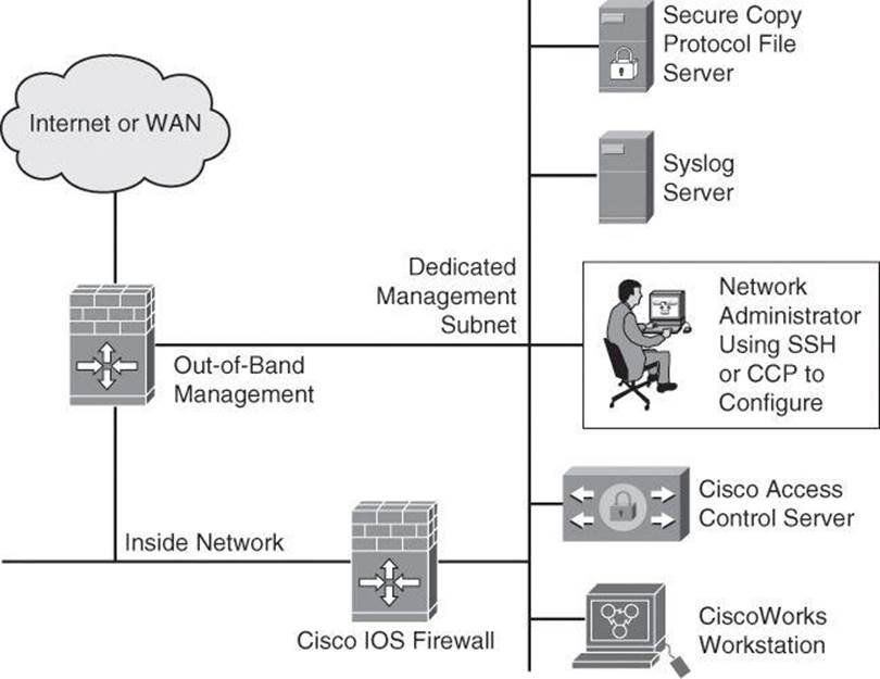
Figure 4-1. Dedicated Management Network
In either case, you can configure a packet filter to allow only the identified administration hosts and preferred protocols to access the router. For example, you can configure the packet filter to permit only SSH requests from the IP address of the administration host to initiate a connection to the routers in the network.
Configuring an SSH Daemon for Secure Management Access
SSH was discussed in Chapter 3, but it’s a topic worth revisiting briefly because it’s part of providing secure management access to the Cisco router. The SSH daemon is a feature that enables an SSH client to make a secure, encrypted connection to a Cisco router. This connection provides functionality similar to that of an inbound Telnet connection, but it also provides strong encryption to be used with local authentication, thus ensuring secure access and communication to network devices such as routers, switches, firewalls, intrusion prevention system (IPS) sensors, and so forth. While Telnet authentication can be as simple as presenting the right password, SSH always requires presenting a username and a password. The SSH daemon in Cisco IOS Software works with publicly and commercially available SSH clients, such as PuTTY, OpenSSH, or Tera Term. To refresh your knowledge of SSH configuration, here are the steps to configure your Cisco router to support an SSH daemon using the CLI:
Step 1. Configure the IP domain name of your network using the ip domain-name domain-name command in global configuration mode:
Router(config)# ip domain-name cisco.com
Note
The domain name and the hostname are used for the generation of the RSA key pairs. If there are any existing key pairs, it is recommended that you overwrite them using the command crypto key zeroize rsa
Step 2. Generate keys to be used with SSH by generating the Rivest, Shamir, and Adleman (RSA) keys using the crypto key generate rsa general-keys modulus modulus-size command in global configuration mode. The modulus determines the size of the RSA key. The larger the modulus, the more secure the RSA key. However, keys with large modulus values take longer to generate, and encryption and decryption operations take longer with larger keys:
Router(config)# crypto key generate rsa general-keys modulus 1024
Note
The minimum recommended key length is modulus 1024. However, as per NIST SP800-313A, a modulus smaller than 2048 bits will be disallowed for federal use after 2013; see http://csrc.nist.gov/publications/nistpubs/800-131A/sp800-131A.pdf.
Step 3. Optionally, to display the generated keys, use the show crypto key mypubkey rsa command in privileged EXEC mode.
Step 4. Configure the time that the router waits for the SSH client to respond using the ip ssh time-out seconds command in global configuration mode:
Router(config)# ip ssh time-out 120
Step 5. Configure the SSH retries (the number of attempts after which the interface will reset) using the ip ssh authentication-retries integer command in global configuration mode:
Router(config)# ip ssh authentication-retries 4
Step 6. Enable vty inbound SSH sessions:
Router(config)# line vty 0 4
Router(config-line)# transport input ssh
The SSH protocol is automatically enabled when you generate the SSH (RSA) keys. Once the keys are created, you can access the router SSH daemon using your SSH client software.
Tip
If you are using a version of Cisco IOS Software that supports both SSHv1 and SSHv2, by default SSH runs in compatibility mode; that is, both SSHv1and SSHv2 connections are honored. If you are running Cisco IOS Release 12.3(4)T or later, you can use the ip ssh version {1 |2} command to configure support for only one version of SSH.
The procedure for connecting to a Cisco router SSH daemon varies depending on the SSH client application that you use. Generally, the SSH client passes your username to the router SSH daemon. The router SSH daemon prompts you for the correct password. After the password has been verified, you can configure and manage the router as if you were a standard vty user.
Tip
Cisco routers with Cisco IOS Software Releases 12.1(3)T and later can act as both SSH clients and SSH daemons. This means that you could initiate an SSH client-to-server session from your router to a central SSH daemon system using the ssh command. SSH employs strong encryption to protect the SSH client-to-server session. Unlike Telnet, where anyone with a sniffer can see exactly what you are sending to and receiving from your routers, SSH encrypts the entire session.
Many vulnerabilities have been reported for SSH Version 1, such as the following root exploit: http://www.doecirc.energy.gov/techbull/archive/CIRCTech02-001.shtml. It is therefore recommended to use SSH Version 2.
Configuring Passwords on Cisco IOS Devices
Strong passwords and similar secrets, such as SNMP community strings, are the primary defense against unauthorized access to your Cisco IOS devices. The first step to secure a device’s administrative access is to configure secure system passwords. The best scalable way to handle most passwords is to maintain them on a TACACS+ or RADIUS authentication server, such as the Cisco Secure Access Control Server (ACS) and Cisco Identity Services Engine (ISE). (TACACS+, RADIUS, and Cisco Secure ACS will be covered later in this chapter.) However, routers can have locally configured passwords for privileged access and can have other password information in their configuration files. This section focuses only on configuring local passwords.
The first step to secure Cisco router administrative access is to configure secure system passwords.

A password can be established on individual lines, such as the console and vty, and for the privileged EXEC mode. Passwords are case sensitive.
By default, the console port does not require a password for console administrative access; however, you should always configure a console port line-level password. As shown in Example 4-1, you can use the line console 0 command followed by the login and password subcommands to require login and establish a login password on the console line.
By default, Cisco routers support up to five simultaneous vty (Telnet) sessions. On the router, the vty ports are numbered from 0 through 4. Example 4-1 shows how you can use the line vty 0 4 command followed by the login and password subcommands to log in to Telnet sessions. However, in Chapter 3 you were introduced to a better practice using the login local command, where an administrator was authenticated against a local database with the global username command.
Example 4-1. Configuring the Console and Virtual Terminal Passwords
R1(config)# line console 0
R1(config-line)# login
R1(config-line)# password M3rcury$12
R1(config-line)# exit
R1(config)# line vty 0 4
R1(config-line)# login
R1(config-line)# password V3nus$2012
The enable secret password global command restricts access to the privileged EXEC mode. You can use the enable secret global configuration command to configure the enable secret password. The enable secret password is always hashed inside the router configuration using a Message Digest 5 (MD5) hashing algorithm; it never appears in cleartext. Hashing will be covered in detail in Chapter 12, “Fundamentals of Cryptography and VPN.”
The enable password is also used to enter enable mode, but this weak password configuration is from earlier versions of Cisco IOS Software. By default, the enable password is not encrypted in the router configuration. The enable password global configuration command was kept for backward compatibility in case you downgrade the router to a version of Cisco IOS Software that does not support the enable secret command. If both enable password and enable secret are configured, the enable password password is ignored and only the enable secret password is used.
If you forget the enable password, regardless of whether it was created using the enable secret command or the enable password command, you have no alternative but to replace it using the Cisco router password recovery procedure specific to your Cisco equipment, which you can find in Cisco Document ID 6130 at http://www.cisco.com/en/US/products/sw/iosswrel/ps1831/products_tech_note09186a00801746e6.shtml.
With the exception of the enable secret password, all Cisco router passwords are stored in plaintext by default within the router configuration. You can view these passwords with the show running-config command. Sniffers can also see these passwords if your TFTP server configuration files traverse an unsecured intranet or Internet connection. If an intruder gains access to the TFTP server where the router configuration files are stored, the intruder is able to obtain these passwords.
As a safeguard against this possible exploit, the service password-encryption command encrypts all the passwords (except the previously hashed enable secret password) in the device configuration file, and will encrypt any passwords you set after entering this command until you turn the command off with the no form of the command. This method, which uses the Vigenère method (also explained in Chapter 12), is not as safe as MD5, which is used with the enable secret command, but prevents casual discovery of the device line-level passwords. To configure password encryption, use the service password-encryption global command. To remove the service password-encryption command, use no service password-encryption.
Also by default, Cisco router auxiliary ports do not require a password for remote administrative access. Administrators sometimes use this port to remotely configure and monitor the router using a dialup modem connection. To combat this vulnerability, you can use the line aux 0command followed by the login and password subcommands to require login and establish a login password on an incoming auxiliary line.
Note
If you want to turn off the EXEC process for a specific line, such as on the auxiliary port, use the no exec command within the line configuration mode.
Setting Timeouts for Router Lines
Another topic important to the security of the management of the device is the line timeouts. As you learned during your CCNA studies, by default, an administrative interface stays active (and logged in) for 10 minutes after the last session activity, and you should adjust timers using theexec-timeout command in line configuration mode for each of the line types used. You can also use Cisco Configuration Professional, introduced in Chapter 3, to configure the exec-timeout for the vty lines.
Configuring the Minimum Length for Router Passwords
Cisco IOS Software Release 12.3(1) and later allow you to set the minimum character length for all router passwords by using the security passwords global configuration command. This command provides enhanced security access to the router by allowing you to specify a minimum password length (0 to 16 characters); this eliminates common passwords that are short and prevalent on most networks, such as lab and cisco. Example 4-2 demonstrates the security passwords command set for a minimum of ten characters.
Example 4-2. security passwords Command
R1(config)# security passwords min-length 10
This command affects username passwords, enable passwords and enable secret passwords, and line passwords that are created after the command is executed. Existing router passwords remain unaffected.
When creating passwords for Cisco routers, always keep the following rules in mind:
• Establish a minimum of ten characters for a password.
• Passwords can include the following:
• Any alphanumeric character, but is case sensitive
• A mix of uppercase and lowercase characters
• Symbols and spaces
• Passwords should not use dictionary words.
• Password-leading spaces are ignored, but no spaces after the first character are ignored.
• Decide when and how often the passwords should be changed.
After the security passwords command has been enabled, any attempt to create a new password that is less than the specified length fails and results in an error message similar to this message:
Password too short - must be at least 10 characters. Password
configuration failed.
Enhanced Username Password Security
As discussed briefly in Chapter 3, Cisco routers can maintain a list of usernames and passwords for performing local login authentication. System administrators can choose to use an MD5 hashing mechanism to encrypt a user password. MD5 hashing of passwords is a much better algorithm than the standard type 7 found in the service password-encryption command.
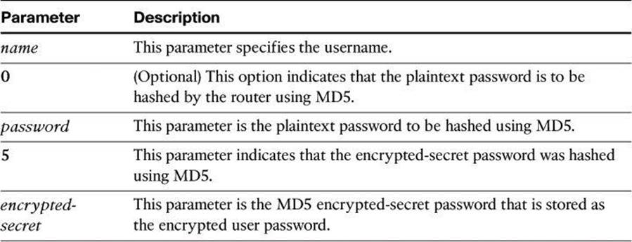
MD5 hashing of a Cisco IOS user password is accomplished with the username secret command in global configuration mode. Administrators can choose to enter a plaintext password for MD5 hashing by the router (option 0), or they can enter a previously encrypted MD5 secret (option5). The syntax for the username secret command is as follows:
username name secret { [0] password | 5 encrypted-secret}
Table 4-1 shows the parameters of the username secret command.
Table 4-1. username secret Parameters
Example 4-3 shows an example of the username secret command.
Example 4-3. username secret Command
R1(config)# username SecAdmin secret 0 Curium2012
R1(config)# username SecAdmin secret 5 $1$uypB$vAWRWP.qFQqb65.KxVxKg1
Dissecting the Hashed Password Format
In Example 4-3, secret 5 means that the password is not in cleartext. The password was hashed with MD5. The hashed password, $1$uypB$vAWRWP.qFQqb65.KxVxKg1, breaks down as follows:
• 1 appearing between the first dollar sign and second dollar sign indicates that the password was hashed with MD5.
• uypB appearing between the second and third dollar signs represents the randomized salt phrase added to the enable secret password prior to hashing.
• A salt value, typically 48 to 128 bits long and randomly generated, helps to produce a hash result that will not match against a lookup table of hashed dictionary words, because dictionary words have fewer bits.
• The salt phrase is stored in your configuration file, and the Cisco IOS router can use it along with the enable password you type to generate an MD5 hash value. If the value calculated from using the salt and the password you just typed in the MD5 algorithm matches the hash result stored in the configuration, such as vAWRWP.qFQqb65.KxVxKg1 in Example 4-3, the router knows that the password that was typed is legitimate.
Securing ROM Monitor
By default, Cisco IOS routers allow a break sequence during startup that forces the router into ROM monitor mode, which can be used for a password recovery procedure. This procedure, if performed correctly, leaves the router configuration intact. Anyone who gains physical access to the router console port can enter ROM monitor mode, reset the enable secret password, and discover the router configuration. You can mitigate this potential security breach by using the no service password-recovery global configuration command, as shown in Example 4-4. This command is a hidden Cisco IOS command and has no arguments or keywords.
Example 4-4. no service password-recovery Command
R1(config)# no service password-recovery
WARNING:
Executing this command will disable password recovery mechanism. Do not execute this
command without another plan for password recovery.
Are you sure you want to continue? [yes/no]: yes
R1(config)#
Note
To recover a device after the no service password-recovery command has been entered, press the Break key within 5 seconds after the image decompresses during the boot. You are prompted to confirm the Break key action. When you confirm the action, the startup configuration is erased, the password recovery procedure is enabled, and the router boots with the factory default configuration. If you do not confirm the Break key action, the router boots normally with the No Service Password-Recovery feature enabled.
Securing the Cisco IOS Image and Configuration Files
Router files are critical to the operations of the router. Operating system images and configuration files are stored in the file system in the router’s flash and nonvolatile memory. The Cisco IOS Resilient Configuration feature enables a router to secure and maintain a working copy of the running image and configuration so that those files can withstand malicious attempts to erase the contents of persistent storage (NVRAM and flash storage).
A great challenge for network operators is the total downtime that is experienced after a router has been compromised and its operating software and configuration data are erased from its persistent storage. The operator must retrieve an archived copy (hopefully one is available) of the configuration and a working Cisco IOS image to restore the router. Recovery must then be performed for each affected router, adding to the total network downtime.
The Cisco IOS Resilient Configuration feature is intended to speed up the recovery process. This feature maintains a secure working copy of the router image and the startup configuration at all times. The user cannot remove these secure files. This set of Cisco IOS image and router running configuration files is referred to as the bootset.
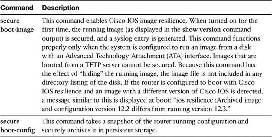
Table 4-2 describes the key commands that are required to secure the Cisco IOS image and running configuration using the secure boot-image command:
R1(config)# secure boot-image
R1(config)# secure boot-config
Table 4-2. secure Commands
Secured files do not appear in the output of a dir command that is issued from an executive shell because the Cisco IOS file system prevents the secure files in a directory from being listed. ROM monitor mode does not have any such restriction and can list and boot secured files. Because the running image and running configuration archives are not visible in the output from the Cisco IOS command dir, use the show secure bootset command to verify the archive existence.
Example 4-5 shows an example of the show secure bootset command output. This command is important to verify that the Cisco IOS image and configuration files have been properly backed up and secured.
Example 4-5. show secure bootset Command Output
R1# show secure bootset
IOS resilience router id FHK085031MD
IOS image resilience version 12.3 activated at 05:00:59 UTC Fri Feb 10 2006
Secure archive flash:c1841-advsecurityk9-mz.123-14.T1.bin type is image (elf) []
file size is 17533860 bytes, run size is 17699528 bytes
Runnable image, entry point 0x8000F000, run from ram
IOS configuration resilience version 12.3 activated at 05:01:02 UTC Fri Feb 10 2
006
Secure archive flash:.runcfg-20060210-050102.ar type is config
configuration archive size 4014 bytes
Configuring Multiple Privilege Levels
Cisco routers enable you to configure various privilege levels for your administrators. You can configure different passwords to control which administrators have access to the various privilege levels. Configuring various privilege levels is especially useful in a help desk environment where you want certain administrators to be able to configure and monitor every part of the router (level 15), while you want other administrators to only monitor, and not configure, the router (customized levels 2 to 14). There are 16 privilege levels, 0 to 15; level 0 is reserved for the user-level access privileges, levels 1 to 14 are levels you can customize, and level 15 is reserved for enable mode privileges.
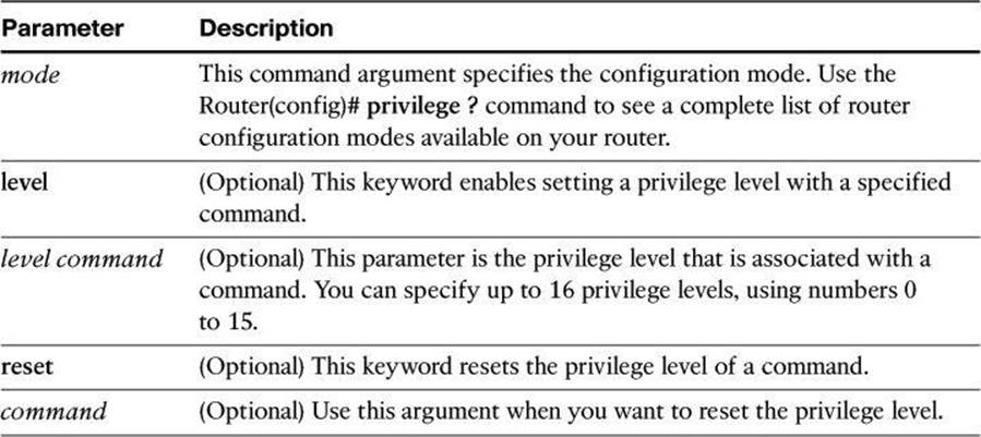
To assign privileges to levels 2 to 14, use the privilege command from global configuration mode:
privilege mode {level level command | reset command}
Table 4-3 describes the parameters for this command and Example 4-6 demonstrates its use.
Table 4-3. privilege Command Parameters
Example 4-6. Configuring Multiple Privilege Levels
R1(config)# privilege exec level 2 ping
R1(config)# enable secret level 2 Cariboo2012
To assign a password to the custom privilege level, use the command enable secret level level password in global configuration mode.
To enter a custom privilege level, use the command enable level and enter the password that was assigned to the custom privilege level.
Example 4-6 sets the ping command to require privilege level 2 or above access and establishes Cariboo2012 as the secret password for privilege level 2. When you enter the enable 2 command, as shown in Example 4-7, the router prompts you for the enable secret password for privilege level 2.
Use the show privilege command to display the current privilege level, as shown in Example 4-7.
Example 4-7. Using the enable level and show privilege Commands
R1> enable 2
Password: Cariboo2012
R1# show privilege
Current privilege level is 2
Configuring Role-Based Command-Line Interface Access
The Role-Based CLI Access feature allows you to create different “views” of router configurations for different users. Views define which commands are accepted from different users and what configuration information is visible to them. With Role-Based CLI Access, you can exercise better control over Cisco networking devices.
Note
Before you create a view, you must enable authentication, authorization, and accounting (AAA) using the aaa new-model command or CCP. AAA configurations are covered in the “Configuring AAA on a Cisco Router Using the Local Database” section of this chapter.
The steps used to configure and confirm a view are as follows:
Step 1. Router> enable view
Step 2. Router# configure terminal
Step 3. Router(config)# parser view view-name
Step 4. Router(config-view)# secret 5 encrypted-password
Step 5. Router(config-view)# commands parser-mode {include | include-exclusive | exclude} [all] [interface interface-name | command]
Step 6. Router(config-view)# exit
Step 7. Router(config)# exit
Step 8. Router# enable [view-name]
Step 9. Router# show parser view [all]
The last two steps allow you to preview the views that you have configured. The next few pages discuss these commands in detail.
The key commands specific to configuring views for Role-Based CLI Access are shown next and are presented again in Example 4-8. When a system is in “root view,” it has all the access privileges of a user who has level 15 privileges. To configure any view for the system, you must be in the root view.
The difference between a user who has level 15 privileges and a root view user is that a root view user can configure a new view and add or remove commands from the view.
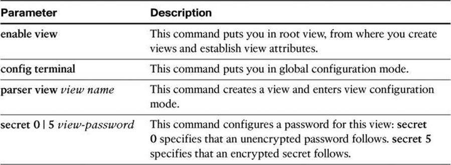
To access the root view, use first the enable view command and then the parser view command:
R1> enable view
R1# configure terminal
R1(config)# parser view view-name
R1(config-view)# secret 0 | 5 view-password
Table 4-4 shows the commands and parameters used to access and modify the root view.
Table 4-4. enable view and parser view Command Parameters
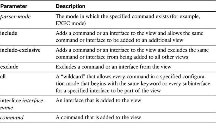
Next, you must assign the allowed commands to the selected view. Use the commands command in view configuration mode to assign the allowed commands. The syntax for this command is as follows:
R1(config-view)# commands parser-mode {include | include-exclusive | exclude} [all]
[interface interface-name | command]
Table 4-5 shows the parameters used with the commands command.
Table 4-5. commands Command Parameters
Example 4-8 displays a complete configuration of a new view, called NetOps.
Example 4-8. Commands to Enable Root View and to Create New Views
R1> enable view
Password:
R1# configure terminal
Enter configuration commands, one per line. End with CNTL/Z.
R1(config)# parser view NetOps
R1(config-view)# secret 0 hardtocrackpw
R1(config-view)# commands exec include ping
R1(config-view)# commands exec include all show
R1(config-view)# commands exec include telnet
R1(config-view)# commands exec include traceroute
R1(config-view)# commands exec include write
R1(config-view)# commands exec include configure
R1(config-view)# commands configure include access-list
R1(config-view)# commands configure include all interface
R1(config-view)# commands configure include all ip
To verify a view, use the enable view command. Enter the name of the view that you want to verify and provide the password to log in to the view. After you are in the view, use the question mark (?) command to verify that the commands available in the view are correct. Example 4-9shows the commands only accessible from the NetOps view at the privilege mode and at the configuration mode.
Example 4-9. Verifying Commands Available to the NetOps View
R1# enable view NetOps
Password: hardtocrackpw
R1#
Jan 3 13:45:03.887: %PARSER-6-VIEW_SWITCH: successfully set to view 'NetOps'.
R1#?
Exec commands:
configure Enter configuration mode
enable Turn on privileged commands
exit Exit from the EXEC
ping Send echo messages
show Show running system information
telnet Open a telnet connection
traceroute Trace route to destination
write Write running configuration to memory, network, or terminal
R1# configure terminal
R1(config)#?
Configure commands:
access-list Add an access list entry
do To run exec commands in config mode
exit Exit from configure mode
interface Select an interface to configure
ip Global IP configuration subcommands
Implementing Secure Management and Reporting
The previous section of this chapter dealt with securing access to Cisco IOS devices. Before we look at AAA configuration and how it assists with secure access, let’s have a look at secure management and reporting, because these features can be useful while troubleshooting AAA configuration.
In this section, we examine the skills necessary to implement secure management and reporting of Cisco IOS devices. The technologies will discuss in this section are as follows:
• Syslog
• Network Time Protocol (NTP)
• Simple Network Management Protocol Version 3 (SNMPv3)
In addition, we will examine some design aspects of a management infrastructure.
Planning Considerations for Secure Management and Reporting
Configuring logging for your Cisco routers is a straightforward operation when your network contains only a few Cisco routers. However, logging and reading information from hundreds of devices can prove to be a challenging proposition and can raise the following issues and considerations:
• What are the most important logs?
• How are important messages separated from routine notifications?
• How do you prevent tampering with logs?
• How do you ensure that time stamps match?
• What log data is needed in criminal investigations?
• How do you deal with the volume of log messages?
• How do you manage all the devices?
• How can you track changes when attacks or network failures occur?
Securing administrative access and device configurations is also a straightforward operation for smaller Cisco router networks. However, managing administrative access and device configurations for many devices can raise questions such as those listed.
Each of these issues is specific to your needs. To identify the priorities of reporting and monitoring, you must get input from management and from the network and security teams. The security policy that you implement should also play a large role in answering these questions.
From a reporting standpoint, most networking devices can send syslog data that can be invaluable when you are troubleshooting network problems or security threats. You can send this data to your syslog analysis host from any device whose logs you want to view. This data can be viewed in real time, on demand, and in scheduled reports. Depending on the device involved, you can choose various logging levels to ensure that the correct amount of data is sent to the logging device. You must also flag device log data within the analysis software to permit granular viewing and reporting. For example, during an attack, the log data that is provided by Layer 2 switches might not be as interesting as the data that is provided by the IPS.
Configuration change management is another issue related to secure management. When a network is under attack, it is important to know the state of critical network devices and when the last known modifications occurred. Creating a plan for change management should be a part of your comprehensive security policy; however, at a minimum, you should record changes using authentication systems on the devices and archive configurations using FTP or TFTP.
Secure Management and Reporting Architecture
In the previous chapter, Figure 3-4 showed a management module with two network segments that are separated by a Cisco IOS router that acts as a firewall and a VPN termination device. In Chapter 3, we introduced the general concept of secure management and reporting, such as the difference between out-of-band (OOB) management and in-band management. Now we will look at some specific guidelines.
Secure Management and Reporting Guidelines
The guidelines for OOB management and in-band management of the architecture are as follows:
• Management guidelines
• Keep clocks on hosts and network devices synchronized.
• Record changes and archive configurations.
• OOB management guidelines
• Provide the highest level of security and mitigate the risk of passing unsecure management protocols over the production network.
• In-band management guidelines to manage or monitor devices:
• Use VPN, SSH, or SSL (HTTPS with CCP) when possible.
• Decide whether the management channel needs to be open at all times.
To ensure that log messages are synchronized with one another, clocks on hosts and network devices must be synchronized. For devices that support it, NTP provides a way to ensure that accurate time is kept on all devices. When you are dealing with an attack, seconds matter, because it is important to identify the order in which a specified attack occurred.
NTP is used to synchronize the clocks of various devices across a network. Synchronization of the clocks within a network is critical for digital certificates and for correct interpretation of events within the syslog data.
Enabling Time Features
Because many things that are involved in the security of your network depend on an accurate date and time stamp, such as security certificates, it is important that the router maintains the correct time.
You can use Cisco Configuration Professional to configure the date and time settings of the router in three ways:
• Synchronize with the local PC clock
• Manually edit the date and time
• Configure NTP
Network Time Protocol
Time synchronization is of essence in secure management and reporting. For management, using time synchronization ensures that digital certificates are used consistently with regard to their expiration and validity. For reporting, time synchronization results in consistent correlation of events across the management infrastructure, and a more effective event and incident detection and analysis.
NTP is a method to synchronize date and time settings for devices on the network. NTP uses User Datagram Protocol (UDP) port 123 and is documented in RFC 1305. Simple Network Time Protocol (SNTP) is a simpler, less secure version of NTP.
When you implement NTP in your network, you can set up your own master clock, or you can use a publicly available NTP server on the Internet. If you implement your own master clock, you should synchronize the private network to Coordinated Universal Time (UTC) via satellite or radio.
You need to be careful when you implement NTP. An attacker can launch a denial of service (DoS) attack by sending bogus NTP data across the Internet to your network in an attempt to change the clocks on network devices, possibly causing digital certificates to become invalid. Further, an attacker could attempt to confuse a network administrator during an attack by disrupting the clocks on network devices. This scenario would make it difficult for the network administrator to determine the order of syslog events on multiple devices.
NTP version 3 (NTPv3) and later support a cryptographic authentication mechanism between NTP peers. You can use this authentication mechanism in addition to access control lists (ACL) that specify which network devices are allowed to synchronize with other network devices, to help mitigate such an attack.
Note
You should weigh the benefits of using clock time from the Internet against the possible risk of doing so and allowing unsecured packets through the firewall. Many NTP servers on the Internet don’t require any authentication of peers and don’t have a requirement of being accurate. Trustworthy sources of time are Symmetricom (http://www.symmetricom.com), Meingerb (http://www.meinberg-usa.com), and National Research Council Canada (http://www.nrc-cnrc.gc.ca/eng/services/time/index.html).
More information on NTP, such as the level of clock hierarchy known as stratum, can be found online at http://en.wikipedia.org/wiki/Network_Time_Protocol.
Using a Cisco IOS Router as an NTP Server
It is possible to configure your Cisco IOS router as an NTP master, which other appliances will contact to synchronize on. The following commands are used to set the router as an NTP master:
router# conf t
router(config)# ntp authenticate
router(config)# ntp trusted-key 99
router(config)# ntp master
router(config)# key chain NTP
router(config-keychain)# key 99
router(config-keychain-key)# key-string PR0PERT1ME
router(config-keychain-key)# end
Using Syslog Logging for Network Security
Syslog is the standard for logging system events. As shown in Figure 4-2, syslog implementations contain two types of systems:
• Syslog servers: These systems are also known as log hosts. These systems accept and process log messages from syslog clients.
• Syslog clients: Syslog clients are routers or other types of Cisco equipment that generate and forward log messages to syslog servers.
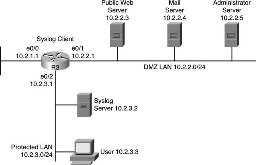
Figure 4-2. Syslog Systems
Note
Performing forensics on router logs can become very difficult if your router clocks are not running the proper time. It is recommended that you use an NTP facility to ensure that all of your routers are operating at the correct time.
If you are not running your own NTP service, you should at least consider synchronizing on an authenticated public NTP service such as the one offered by the National Research Council Canada at http://www.nrc-cnrc.gc.ca/eng/solutions/advisory/calibration/time_frequency.html#authenticated.
Also note that it is recommended to have redundant syslog servers on a network. Many approaches exist on how to use the two systems, such as
• Have the network device send its syslog messages at both servers.
• Have the network device send its syslog messages to only one server but have that server, keeping a copy of the message, forward it immediately to the second server.
Implementing Log Messaging for Security
Implementing a router logging facility is an important part of any network security policy. Cisco routers can log information regarding configuration changes, ACL violations, interface status changes, and many other types of events. Cisco routers can send log messages to several different facilities. You should configure the router to send log messages to one or more of the following items:
• Console: Console logging is used when modifying or testing the router while it is connected to the console. Messages sent to the console are not stored by the router and, therefore, are not very valuable as security events.
• Terminal monitor: The console port works at 9600 bauds and thus can’t simultaneously handle a large quantity of log messages. It is therefore recommended that you remotely connect to the device, using SSH preferably, and that you issue the terminal monitor command to receive the log message on this current vty session. This is the subject of the next bullet.
• Terminal lines: You can configure enabled EXEC sessions to receive log messages on any terminal lines. Similar to console logging, this type of logging is not stored by the router and, therefore, is valuable only to the user on that line.
• Buffered logging: You can direct a router to store log messages in router memory. Buffered logging is a little more useful as a security tool but has the drawback of having events cleared whenever the router is rebooted. Note also that buffers can be written to flash.
• SNMP traps: Certain router events can be processed by the router SNMP agent and forwarded as SNMP traps to an external SNMP server. SNMP traps, addressed to destination port UDP 162, are a viable security logging facility but require the configuration and maintenance of an SNMP system.
• Syslog: You can configure Cisco routers to forward log messages to an external syslog service, destination port UDP 514. This service can reside on any number of servers, including Microsoft Windows and UNIX-based systems, or since the Cisco Security MARS appliance is at end-of-life status, consider using Cisco Security Manager (CSM) or a Cisco ecosystem partner for Security Information and Event Management System (SIEM), such as Splunk, as a syslog destination. Syslog is the most popular message logging facility because it provides long-term log storage capabilities and a central location for all router messages.
Cisco router log messages fall into one of eight levels, as shown in Table 4-6. The lower the level number, the higher the severity level, as the log messages in the table denote.
Table 4-6. Cisco Router Log Severity Messages
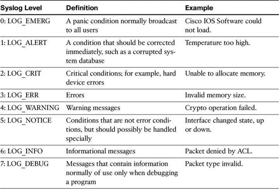
Note
When entering logging levels in commands, you must specify the level name or the level number.
Cisco router log messages contain three main parts:
• Time stamp
• Log message name and severity level
• Message text
Figure 4-3 shows a syslog entry example for a level 5 syslog message, indicating that someone has configured the router using the vty 0 port.
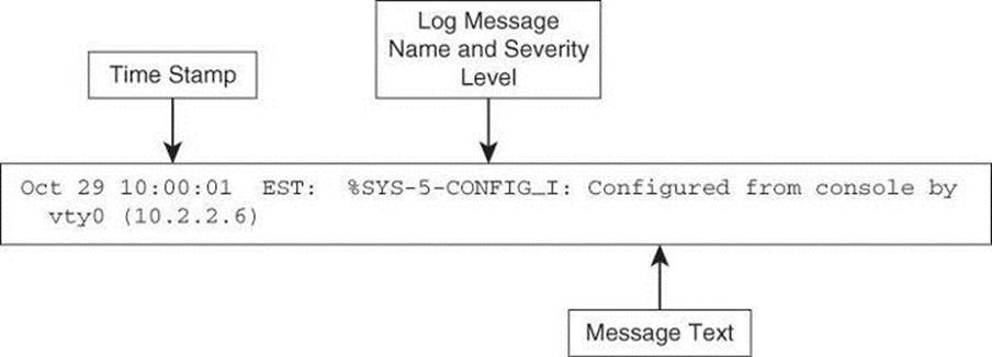
Figure 4-3. Log Message Format
Figure 4-4 illustrates the configuration of syslog settings using Cisco Configuration Professional. Navigate to Configure > Router > Logging to enable logging of system messages, and to specify logging hosts where logs can be kept.
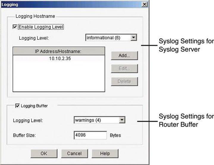
Figure 4-4. Enabling Syslog Logging on CCP
By clicking Edit, you can change the syslog settings and specify the level of logging messages that you want to send and to collect, and enter the hostname or IP address of multiple logging hosts.
The logging settings are shown in Figure 4-4. The top of the window allows the configuration of syslog server parameters. The bottom half allows the configuration of the router buffers as receivers of router syslog messages.
When defining the logging level for a syslog server, the log collects all messages from the level you choose plus all messages from lower levels, or the router sends all messages of the level you choose plus all messages of lower levels to the logging hosts. For example, if you choose notifications (5), the log collects or sends messages of levels 0 through 5. Firewall logging messages require a logging level of debugging (7), and application security logging messages require a level of informational (6).
Using SNMP to Manage Network Devices
SNMP is another management option, not only for messaging and notifications via SNMP traps and informs, but also as a general management framework. SNMP was developed to manage nodes, such as servers, workstations, routers, switches, hubs, and security appliances, on an IP network. All versions of SNMP are application layer protocols that facilitate the exchange of management information between network devices. SNMP is part of the TCP/IP protocol suite. SNMP enables network administrators to manage network performance, find and solve network problems, and plan for network growth.
SNMP Version 1 (SNMPv1) and SNMP Version 2 (SNMPv2) are based on three concepts:
• Managers (network management systems [NMS] installed on servers)
• Agents (installed on managed nodes)
• Management Information Bases (MIB)
In any configuration, at least one manager node runs SNMP management software. Network devices that need to be managed, such as switches, routers, servers, and workstations, are equipped with an SMNP agent software module. The agent is responsible for providing access to a local MIB of objects that reflects the resources and activity at its node.
MIBs
A Management Information Base is a database of the objects that can be managed on a device. The managed objects, or variables, can be set or read to provide information on the network devices and interfaces.
The SNMP manager can retrieve, or “get,” information from the agent, and change, or “set,” information in the agent, as shown in Figure 4-5. Sets can change variables (settings, configuration) in the agent device or initiate actions in devices. A reply to a set indicates the new setting in the device. For example, a set can cause a router to reboot, send a configuration file, or receive a configuration file. SNMP traps enable an agent to notify the management station of significant events by sending an unsolicited SNMP message.
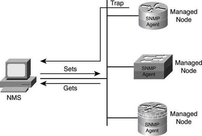
Figure 4-5. SNMPv1/v2 Architecture
The actions of gets and sets are the vulnerabilities that open SNMP to attack.
SNMPv1 and SNMPv2 use a community string to access router SNMP agents. SNMP community strings act like passwords. An SNMP community string is a text string that can authenticate messages between a management station and an SNMP engine:
• If the manager sends one of the correct read-only community strings, it can get information but not set information in an agent.
• If the manager uses one of the correct read-write community strings, it can get or set information in the agent.
In effect, having set access to a router is equivalent to having the enable password of the router.
SNMP agents accept commands and requests only from SNMP systems using the correct community string. By default, most SNMP systems use “public” as a community string. If you configure your router SNMP agent to use this commonly known community string, anyone with an SNMP system is able to read the router MIB. Because router MIB variables can point to things such as routing tables and other security-critical parts of the router configuration, it is extremely important that you create your own custom SNMP community strings.
SNMPv3 Architecture
In its natural evolution, the current version of SNMPv3 addresses the vulnerabilities of earlier versions by including three important services: authentication, privacy, and access control.
SNMPv3 is an interoperable, standards-based protocol for network management. SNMPv3 uses a combination of authenticating and encrypting packets over the network to provide secure access to devices, as shown in Figure 4-6. SNMPv3 provides the following security features:
• Message integrity: Ensures that a packet has not been tampered with in transit
• Authentication: Determines that the message is from a valid source
• Encryption: Scrambles the contents of a packet to prevent it from being seen by an unauthorized source
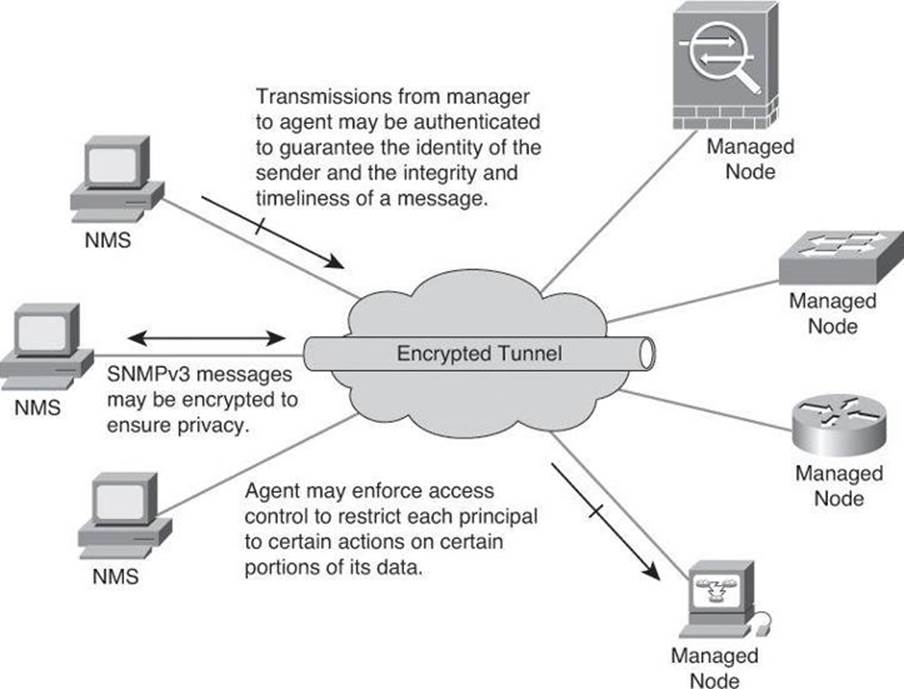
Figure 4-6. SNMPv3 Architecture
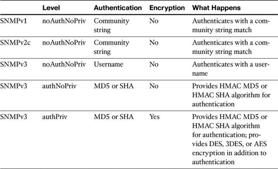
SNMPv3 provides for a combination of both security model and security level, which determines the security mechanism that will be used when handling an SNMP packet.
A security model is an authentication strategy that is set up for a user and the group in which the user resides. Currently, Cisco IOS Software supports three security models: SNMPv1, SNMPv2c, and SNMPv3. A security level is the permitted level of security within a security model. The security level is a type of security algorithm that is performed on each SNMP packet. There are three security levels:
• noAuth: This security level authenticates a packet by a string match of the username or community string.
• auth: This level authenticates a packet by using either the Hashed Message Authentication Code (HMAC) with Message Digest 5 (MD5) method or the HMAC with Secure Hash Algorithms (SHA) method. Both methods are described in RFC 2104, HMAC: Keyed-Hashing for Message Authentication.
• Priv: This level authenticates a packet by using either the HMAC MD5 or HMAC SHA algorithm and encrypts the packet using the Data Encryption Standard (DES), Triple DES (3DES), or Advanced Encryption Standard (AES) algorithm.
Note
Only SNMPv3 supports the auth and priv security levels.
Table 4-7 identifies what the combinations of security models and levels mean. As mentioned earlier, hashing and encryption will be explained in Chapter 12.
Table 4-7. AAA Accounting Using Named Method Lists Procedure
Enabling SNMP Options Using Cisco CCP
Figure 4-7 illustrates the configuration of SNMP settings using Cisco Configuration Professional. Navigate to Configure > Router > SNMP to enable SNMP, set SNMP community strings, and enter SNMP trap receiver information.
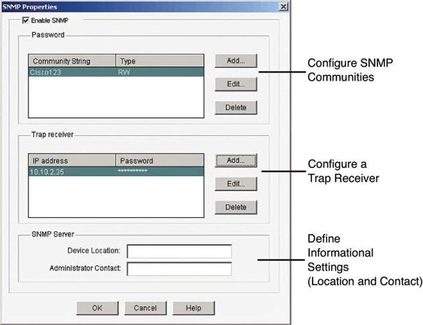
Figure 4-7. Enabling SNMP with CCP
Configuring AAA on a Cisco Router
Previously in this chapter, we discussed how to create a more secure management and reporting environment. A significant part of that environment is AAA. In Chapter 3, we briefly discussed the use of AAA with regard to management plane security. In this section, we will see how AAA can be implemented locally or centrally.
As mentioned, one of the options you have when configuring your network to work with AAA is to use a local username and password database to provide security greater than a simple password. It is likely that smaller organizations will configure AAA to operate locally.
Authentication, Authorization, and Accounting
Access control is the way you control who is allowed access to the access server or router and which services they are allowed to use once they have access. AAA network security services provide the primary framework through which you set up access control on your router. AAA services provide a higher degree of scalability than the line-level and privileged EXEC authentication commands alone.
Network and administrative access security in the Cisco environment, whether it involves campus access or VPN access, is based on a modular architecture that has three functional components:
• Authentication: Authentication requires users and administrators to prove that they really are who they say they are. Authentication is established using a username and password, challenge and response, token cards, and other methods, such as “I am user student and my password validateme proves it.”
• Authorization: After authenticating the user and administrator, authorization services decide which resources the user and administrator are allowed to access and which operations the user and administrator are allowed to perform, such as “User student can access host serverXYZ using Telnet.”
• Accounting and auditing: Accounting records what the users and administrators actually did, what they accessed, and for how long they accessed it. Accounting keeps track of how network resources are used, such as “User student accessed host serverXYZ using Telnet for 15 minutes.”
Two examples of AAA implementation include authenticating remote users that are accessing the corporate LAN through VPN connections (as shown in Figure 4-8) and authenticating administrator access to the router console port, auxiliary port, and vty ports.
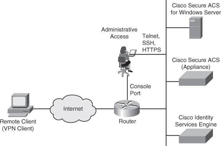
Figure 4-8. Implementing Cisco AAA
Cisco networking products support AAA access control using a local usernames and passwords database or remote security server databases. A local security database was introduced in Chapter 3 with the username command, and covered in detail earlier in this chapter with Table 4-1. A remote security server database is a separate server that provides AAA services for multiple network devices and a large number of network users by running RADIUS or TACACS+ protocols.
Note
Omitted from Figure 4-8 is “NAS services.” If your Cisco router accepts dialup connections, the router is described as a network access server (NAS). With the popularity of VPN access, we don’t hear as much nowadays about remote-access dialup services, but they are still around, which explains why Table 4-8 briefly discusses NAS ports.
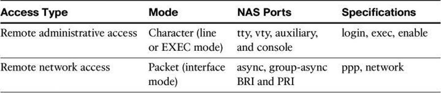
Table 4-8. Router Access
Cisco provides many ways to implement AAA services for Cisco routers, all of which are covered in greater detail later in this chapter:
• Self-contained AAA: AAA services can be self-contained in the router itself. This form of authentication is also known as local authentication, with the username command.
• Cisco Secure Access Control Server (ACS) for Windows: AAA services on the router or NAS contact an external Cisco Secure ACS for Microsoft Windows system for user and administrator authentication.
Note
In 2011, Cisco announced the end of life of Cisco Secure ACS for Windows. It is still vastly used and it is still supported, and therefore we are briefly covering it in this book. However, if you are planning a new implementation for external authentication, the next two options are your current Cisco choices.
• Cisco Secure ACS: A policy-driven access control system and an integration point for network access control and identity management. The ACS 5.2 software runs either on a dedicated Cisco 1121 Secure Access Control System appliance or on a VMware server.
• Cisco Identity Services Engine (ISE): Cisco ISE is the new-generation centralized policy engine for business-relevant policy definition and enforcement. Cisco ISE consolidates features and functions that are found in Cisco Secure ACS and Network Admission Control (NAC) products, to deliver all the necessary services that are required by an enterprise network (AAA, profiling, posture, and guest management) in a single appliance platform. To learn more about ISE, check out TechWiseTV on YouTube for “Fundamentals of ISE.”
Authenticating Router Access
You can use AAA to secure two different types of router access mode. The mode refers to the format of the packets that are requesting AAA services:
• Character mode: A user is sending a request to establish an EXEC mode process with the router, for administrative purposes. The user wishes to get the router prompt to start managing the router as the administrator.
• Packet mode: A user is sending a request to establish a dialup connection through the router with a device on the network. The user does not wish to get the router prompt. The sole purpose of connecting to the router is to get access to network resources. This is no longer a frequent scenario because remote users typically connect to organization resources with a VPN connection instead of a dialup connection.
With the exception of accounting commands, all the AAA commands apply to both character mode and packet mode.
For a truly secure network, you must configure the router to secure administrative access and remote LAN network access using AAA services.
Table 4-8 compares the router access modes, port types, and AAA command elements.
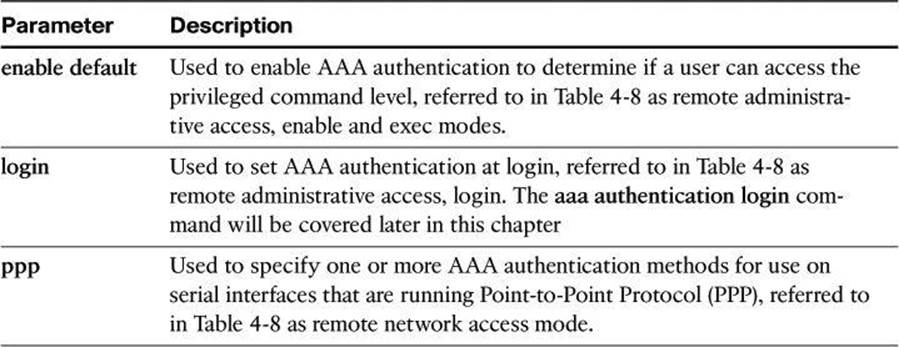
The aaa authentication command can be used for different authentication settings. Table 4-9 describes common options of the aaa authentication command. Many more options are available than those presented here.
Table 4-9. aaa authentication Command Parameters
Configuring AAA Authentication and Method Lists
AAA authentication is based on method lists as its building blocks. A method list is a sequential list describing the authentication methods to be queried in order to authenticate a user. Method lists enable you to designate one or more security protocols to be used for authentication, thus ensuring a backup system for authentication in case the initial method fails.
Cisco IOS Software uses the first listed method to authenticate users. If that method fails to respond, the Cisco IOS Software selects the next authentication method that is listed in the method list. This process continues until there is successful communication with a listed authentication method, or all methods that are defined in the method list are exhausted. In Figure 4-9, the default method list showcases two fallback methods. A typical configuration usually includes an AAA server database as the first method and the local database as a fallback method.
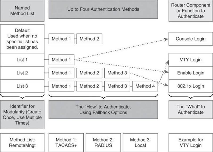
Figure 4-9. Modular Objects in AAA Configuration
It is important to note that the Cisco IOS Software attempts authentication with the next listed authentication method only when there is no response from the previous method. If authentication fails at any point in this cycle—meaning that the security server or local username database responds by denying the user access—the authentication process stops and no other authentication methods are attempted.
Each method list is an individual configuration object. They can be assigned to multiple router components or function to provide authentication services. In Figure 4-9, the authentication methods in List 1 are assigned to both console and enable logins. List 2 methods apply to 802.1X logins, and List 3 methods apply to vty logins. Any other component not assigned a method list will use the methods on the default list.
At the bottom of Figure 4-9, we have an example where a method list called RemoteMngt is created and assigned to vty logins. When an administrator connects to the device with an SSH session, the administrator’s credentials will first be checked against a TACACS+ server. If there is no communication with the TACACS+ server, the administrator’s credentials will be presented to the RADIUS server, and if that communication fails as well, the administrator’s credentials will be checked against the local database. The difference between the TACACS+ and RADIUS protocols will be discussed later in this chapter.
Although it is not common to see this level of complexity and granularity for different access methods on the same router, the modular configuration that is based on method lists allows for this level of granularity and flexibility.
Configuring AAA on a Cisco Router Using the Local Database
If you have only a few devices that provide remote access to your network for a limited number of users, you can store username and password security information locally on the Cisco devices. This is referred to as local authentication on a local security database. The following are local authentication characteristics:
• Used for small networks
• Stores usernames and passwords in the Cisco router
• Users authenticate against the local security database in the Cisco router
• Does not require an external database
The system administrator must populate the local security database by specifying username and password profiles for each user that might log in. This local authentication is difficult to scale because
• There is limited persistent storage on network devices (running and startup configs).
• If the same credentials are used to access multiple network devices, those credentials require manual replication on concerned devices.
Local authentication typically works as follows, as shown in Figure 4-10:
1. The client establishes a connection with the router.
2. The router prompts the user for a username and password.
3. The router authenticates the username and password in the local database. The user is authorized to access the network based on information in the local database.
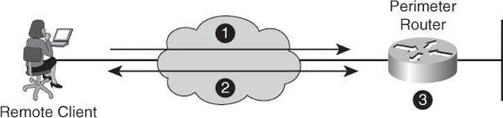
Figure 4-10. Implementing Authentication Using Local Services
Configuring AAA Local Authentication
To configure AAA local services to authenticate administrator access (character mode access) or network access (packet mode) that includes VPN access, follow these general steps:
• Add usernames and passwords to the local router database for users who need administrative access to the router.
• Enable AAA globally on the router, or confirm that it is already enabled.
• Configure AAA parameters on the router. These parameters include authentication policies at a minimum, using method lists for the desired access type. Authorization and accounting policies can optionally be configured.
• Confirm and troubleshoot the AAA configuration.
The first step to configure AAA services for local authentication is to create users. Local user accounts can be configured by navigating to Configure > Router > Router Access > User Accounts/View and clicking Add, as shown in Figure 4-11. This window enables you to define accounts and passwords that will enable users to authenticate when logging in to the router using HTTP, Telnet, PPP, or some other means. Privilege levels and CLI views can also be configured using this option by adding a new user or editing existing users.
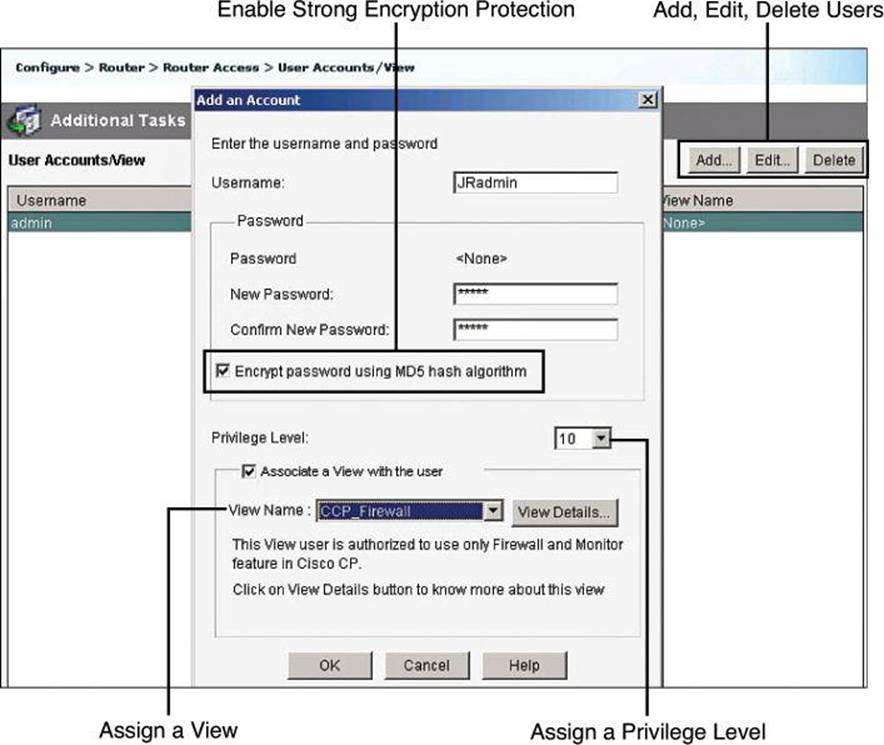
Figure 4-11. Configuring Local User Accounts Using CCP
The following are the detailed steps for adding a local user account:
Step 1. Choose Configure > Router > Router Access > User Accounts/View.
Step 2. Click Add to add a new user.
Step 3. In the Add an Account dialog box, enter the username and password in the appropriate fields to define the user account.
Step 4. From the Privilege Level drop-down list, choose 15 unless you have defined lesser privilege levels, as shown in Figure 4-11.
Step 5. If you have defined views, you can check the Associate a View with the User check box and choose from the View Name drop-down list a view that you want to associate with this user.
Step 6. Click OK.
Enabling AAA Authentication Policy
Authentication policies for local access can be configured by navigating to Configure > Router > AAA > AAA Summary. From this window, shown in Figure 4-12, you can enable AAA globally by clicking the Enable AAA button and then clicking Yes in the Enable AAA dialog box that appears. As a precaution and a first level of protection, Cisco Configuration Professional will enable authentication and authorization for the vty lines and authentication for the console line using the local database of the router. A warning message lets the administrator know about this default policy, which is also displayed in the summary window when the commands are delivered to the router. Other authentication policies can be created using authentication method lists.
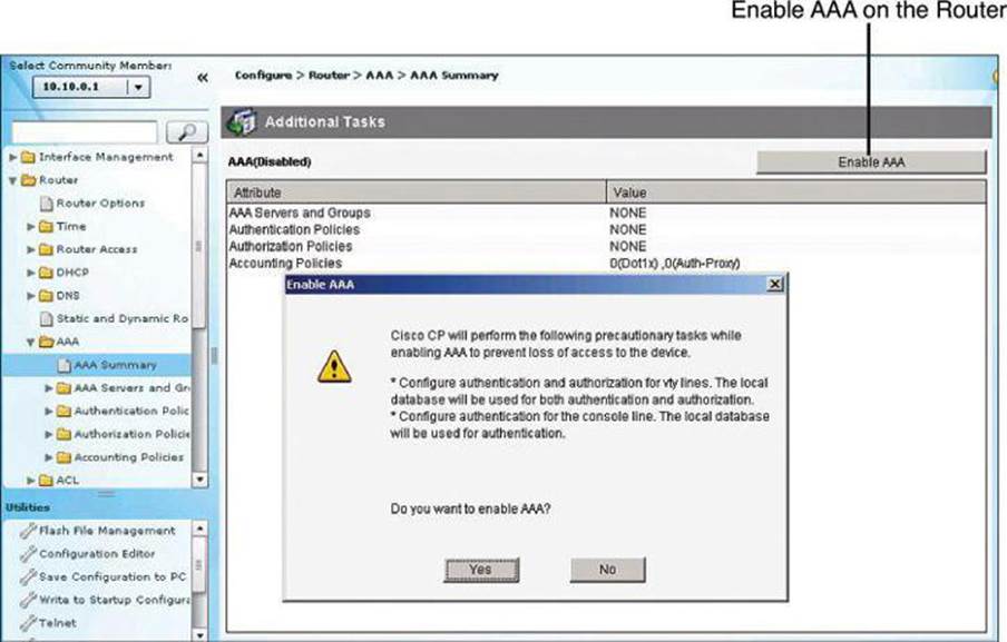
Figure 4-12. Enabling and Disabling AAA Using CCP
Figure 4-13 shows the resulting CCP configuration following the enabling of AAA.
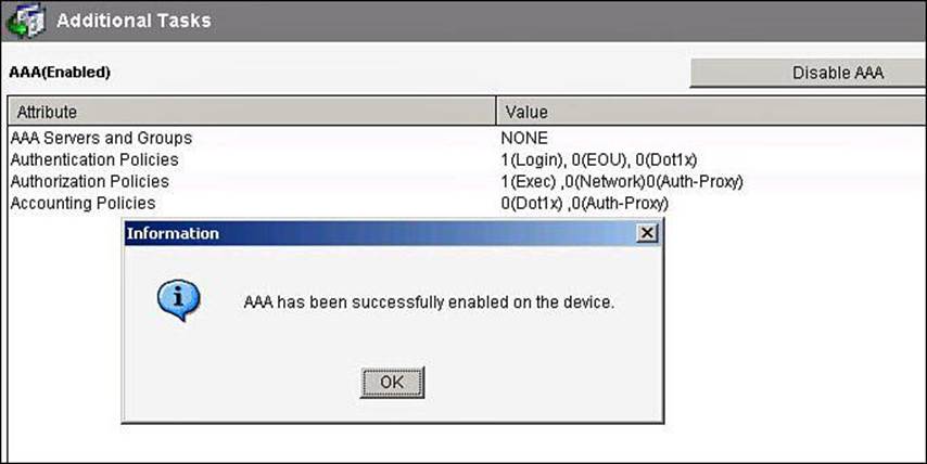
Figure 4-13. AAA Summary After AAA Is Enabled
Configuring Method Lists
Authentication method lists can be created or edited by navigating to Configure > Router > AAA > Authentication Policies > Login. The default method list is shown in the background window of Figure 4-14, as well as how to add a new list or edit an existing list.
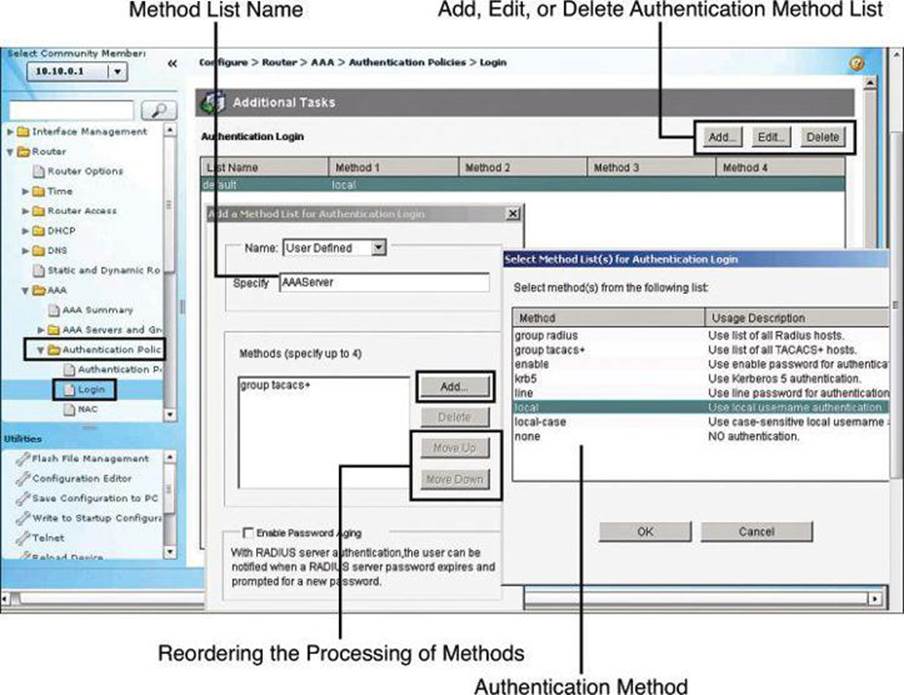
Figure 4-14. Configuring AAA Authentication Method Lists
The method list requires a name so that you can later assign the list to the router function requiring authentication (management access, in our example). This name is specified in the Add a Method List for Authentication Login dialog box, shown on the left in Figure 4-14.
The authentication methods comprise a list, which you can modify by clicking Add to add a new method to the list. The resulting Select Method List(s) for Authentication Login dialog box, shown on the right in Figure 4-14, displays the available authentication methods and allows you to select among these methods. You can specify up to four methods and place them in the list in the order in which you want the router to use them. As explained earlier in conjunction with Figure 4-9, the router will attempt the first method in the list. If the authentication request receives a PASS or a FAIL response, the router does not query further. If the router does not receive a response by using the first method, it uses the next method in the list, and continues to the end of the list until it receives a PASS or a FAIL response. Each method in the list represents, then, a backup or fallback option to the previous method.
You can change the order of processing of the method list in the Add a Method List for Authentication Login dialog box. Click Move Up to move a method up the list. Click Move Down to move a method further down the list. The method “none” will always be last in the list. No other method in the list can be moved below it. This is a Cisco IOS restriction. Cisco IOS will not accept any method name after the method name “none” has been added to a method list. Method name “none” should be used with care, because it removes the requirement of having to provide authentication.
AAA Authentication CLI Configuration
Table 4-10 describes common options of the aaa authentication login command. More options are available than those presented here.
Table 4-10. aaa authentication login Command Parameters
Example 4-10 shows a CLI configuration for local authentication, using the following commands:
• aaa new-model: Enables AAA.
• aaa authentication login default local: Defines the default method list for login authentication using the local database.
• aaa authentication login list name: Defines a custom method list for login authentication using the local database, using the enable password as a fallback option. In Example 4-10, the list name is MGT-ACCESS.
• username: Adds usernames and passwords to the local security database.
• login authentication: Assigns a method list to an access line; applied to the console line in Example 4-10.
Maximum Number of Login Attempts and Login Delay
To further secure administrative access to the router, you can specify the maximum number of failed AAA login attempts that can occur before an account is locked out, using the aaa local authentication attempts max-fail command in global configuration mode, as shown inExample 4-10.
Not used in Example 4-10 is the login delay command. The aaa local authentication attempts max-fail command differs from the login delay command in how it handles failed attempts. The aaa local authentication attempts max-fail command locks the user account if the authentication fails. This account stays locked until it is cleared by an administrator. The login delay command introduces a delay between failed login attempts without locking the account.
Example 4-10. AAA CLI Configuration Example with Local Authentication
R1(config)# aaa new-model
R1(config)# aaa local authentication attempts max-fail 10
R1(config)# aaa authentication login default local
R(config)# aaa authentication login MGT-ACCESS local enable
R1(config)# enable secret SnowyDay2012
R1(config)# username admin privilege 15 view root secret sanfran2012
R1(config)# username FWadmin privilege 10 view CCP_Firewall secret 1StopUn0w
R1(config)# line con 0
R1(config-line)# login authentication MGT-ACCESS
R1(config-line)# end
R1# debug aaa authentication
To display information on AAA authentication, use the debug aaa authentication command in privileged EXEC command mode. Example 4-11 contains debug output for an unsuccessful AAA authentication followed by a successful authentication on the router console, using the local user database defined in Example 4-10.
Example 4-11. Troubleshooting Using the debug aaa authentication Command
User Access Verification
Username: wrongusername
Password:
Feb 11 11:06:47.971: AAA/BIND(0000001B): Bind i/f
Feb 11 11:06:47.971: AAA/AUTHEN/LOGIN (0000001B): Pick method list 'MGT-ACCESS'
Feb 11 11:06:48.223: AAA/AUTHEN/ENABLE(0000001B): Processing request action LOGIN
Feb 11 11:06:48.223: AAA/AUTHEN/ENABLE(0000001B): Done status GET_PASSWORD
Feb 11 11:06:49.231: AAA/AUTHEN/ENABLE(0000001B): Processing request action LOGIN
Feb 11 11:06:49.235: AAA/AUTHEN/ENABLE(0000001B): Done status FAIL - bad password
% Authentication failed
Username: admin
Feb 11 11:06:51.239: AAA/AUTHEN/LOGIN (0000001B): Pick method list 'MGT-ACCESS'
Password:
R1>
AAA on a Cisco Router Using Cisco Secure ACS
Cisco Secure Access Control Server (ACS) provides a centralized identity networking solution and simplified user management experience across all Cisco devices and security management applications. This section describes Cisco Secure ACS and its uses, the requirements for installing Cisco Secure ACS for Windows, the Cisco Secure ACS installation procedure, and its configuration for router AAA services.
Cisco Secure ACS Overview
Local implementations of AAA, as previously explained, do not scale well. Most corporate environments have multiple Cisco routers and NASs with multiple router administrators and hundreds or thousands of users needing access to the corporate LAN. Maintaining local databases for each Cisco router and NAS for this size of network is not feasible.
To solve this challenge, you can use one or more Cisco Secure ACS systems (servers or engines) to manage the entire user and administrative access needs for an entire corporate network using one or more databases. External AAA systems, such as the Cisco Secure ACS for Windows, Cisco Secure ACS appliance, or Cisco Identity Services Engine (ISE), communicate with Cisco routers and NASs using the TACACS+ or RADIUS protocols to implement AAA functions. This allows you to make changes to user accounts and passwords in a centralized place (the ACS server) and have all the Cisco routers and NASs in your network access this information.
Figure 4-15 shows the following steps of the authentication and authorization process using an external Cisco Secure ACS system to provide AAA services to a network:
Step 1. The client establishes a connection with the router.
Step 2. The router prompts the user for a username and password.
Step 3. The router passes the username and password to the Cisco Secure ACS (server or engine).
Step 4. The Cisco Secure ACS authenticates the user. The user is authorized to access the router (administrative access) or the network based on information found in the Cisco Secure ACS database.
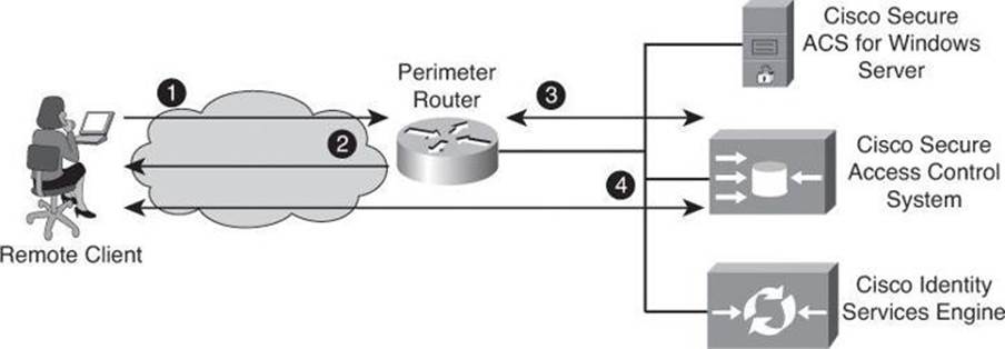
Figure 4-15. Implementing Authentication Using External Servers
Cisco Secure ACS, in its appliance and software form factors, is a highly scalable, high-performance ACS that operates as a centralized RADIUS and TACACS+ server that provides the following features:
• Extends access security by combining authentication, user access, and administrator access with policy control within a centralized identity networking solution
• Allows greater flexibility and mobility, increased security, and user-productivity gains
• Enforces a uniform security policy for all users regardless of how they access the network
• Reduces the administrative and management burden involved in scaling user and network administrator access to the network
Cisco Secure ACS uses a central database, which allows it to centralize the control of all user privileges and enables hundreds or thousands of access points throughout the network to reference those privileges. Cisco Secure ACS provides detailed reporting and monitoring capabilities of user behavior, access connections, and device configuration changes. This feature has become extremely important for organizations trying to comply with Sarbanes-Oxley Act regulations. Cisco Secure ACS supports a broad variety of access connections, including wired and wireless LAN, dialup, broadband, content, storage, VoIP, firewalls, switches, and VPNs.
You can leverage the Cisco Secure ACS framework to control administrator access and configuration for all the network devices in your network that support RADIUS and TACACS+. The following are some of the advanced features of Cisco Secure ACS:
• Automatic service monitoring
• Database synchronization and importing of tools for large-scale deployments
• Lightweight Directory Access Protocol (LDAP) user authentication support
• User and administrative access reporting
• Restrictions to network access based on criteria such as the time of day and the day of week
• User and device group profiles
• Token-based authentication
Cisco Secure ACS is an important component of the Cisco Identity Based Networking Services (IBNS) architecture. Cisco IBNS is based on port-security standards such as IEEE 802.1x and Extensible Authentication Protocol (EAP), and extends security from the perimeter of the network to every connection point inside the LAN. You can deploy new policy control, such as per-user quotas, VLAN assignments, and ACLs, within this new architecture because of the extended capabilities of Cisco switches and wireless access points to query Cisco Secure ACS over the RADIUS protocol. Please note that IBNS is being superseded by TrustSec. Have a look at TechWiseTV’s “Fundamentals of TrustSec” on YouTube to learn more.
Cisco Secure ACS is also an important component of Cisco Network Admission Control (NAC). Cisco NAC is an industry initiative sponsored by Cisco that uses the network infrastructure to enforce security-policy compliance on all devices seeking to access network computing resources, thereby limiting damage from viruses and worms. With NAC, customers can choose to allow network access only to compliant and trusted endpoint devices (for instance, PCs, servers, and personal digital assistants [PDA]) and can restrict the access of noncompliant devices. Cisco NAC is part of the Cisco Self-Defending Network initiative and is the foundation for enabling NAC on Layer 2 and Layer 3 networks. Future phases extend endpoint and network security interoperation to include dynamic incident-containment capabilities. This innovation enables compliant system elements to report misuse emanating from rogue or infected systems during an attack. Thus, infected systems can be dynamically quarantined from the rest of the network to significantly reduce virus, worm, and blended-threat propagation.
Cisco Secure ACS is a powerful access control server with many high-performance and scalability features for any organization growing its WAN or LAN. The following lists the main benefits of Cisco Secure ACS:
• Ease of use: A web-based user interface simplifies and distributes the configuration for user profiles, group profiles, and Cisco Secure ACS configuration.
• Scalability: Cisco Secure ACS is built to support large networked environments with support for redundant servers, remote databases, and database replication and backup services.
• Extensibility: LDAP authentication forwarding supports the authentication of user profiles that are stored in directories from leading directory vendors, including Sun, Novell, and Microsoft.
• Management: Microsoft Windows Active Directory support consolidates Windows username and password management and uses the Windows Performance Monitor for real-time statistics viewing.
• Administration: Different access levels for each Cisco Secure ACS administrator and the ability to group network devices together make it easier and more flexible to control the enforcement and changes of security policy administration over all of the devices in a network.
• Product flexibility: Because Cisco IOS Software has embedded support for AAA, Cisco Secure ACS can be used across virtually any NAS that Cisco sells (the Cisco IOS Software release must support RADIUS or TACACS+). Cisco Secure ACS is now available in an appliance format or in a virtual machine format. Until version 4.x, in additional to being offered as an appliance, it was also available as software call Cisco Secure ACS for Windows and as a small appliance called Cisco Secure ACS Express, mentioned later in this chapter.
• Integration: Tight coupling with Cisco IOS routers and VPN solutions provides features such as Multichassis Multilink PPP and Cisco IOS Software command authorization.
• Third-party support: Cisco Secure ACS offers token server support for any one-time password (OTP) vendor that provides an RFC-compliant RADIUS interface, such as RSA, PassGo, Secure Computing, Vasco, or CryptoCard.
• Control: Cisco Secure ACS provides dynamic quotas to restrict access based on the time of day, network use, number of logged sessions, and the day of the week.
Cisco Secure ACS for Windows
The last available version of Cisco Secure ACS running on Windows Server was version 4.2. This 4.2 version was also available in two additional form factors: VMware ESX Server, and as a dedicated appliance. In 2011, Cisco announced the end of life of Cisco Secure ACS 4.2 and thus the end of ACS for Windows Server. The new 5.2 version, covered later in the chapter, does not support ACS for Windows Server. Version 5.2 is only available as a VM or as a dedicated appliance. Because Cisco Secure ACS for Windows is still vastly used, we are briefly covering this option even though it has reached end-of-life status.
Cisco Secure ACS 4.2 for Windows must meet certain minimum hardware and operating system requirements, covered briefly in the next section. For third-party software requirements, such as web browsers and Java, consult the release notes.
The server that will be running Cisco Secure ACS must meet the following minimum hardware requirements:
• Pentium IV processor that is 1.8 GHz or faster
• 1 GB of RAM
• At least 1 GB of free disk space; if you are running the database on the same computer, more disk space is required
• Minimum graphics resolution of 256 colors at 800×600 pixels
Cisco Secure ACS 4.2 for Windows supports the English-language versions of the following Microsoft Windows operating systems:
• Windows 2000 Server, with Service Pack 4 installed
• Windows 2000 Advanced Server, with the following conditions:
• Service Pack 4 installed
• Without Microsoft Clustering Service installed
• No other features specific to Windows 2000 Advanced Server enabled, such as Terminal Services
• Windows Server 2003 Service Pack 1, Enterprise Edition or Standard Edition
• Windows Server 2003, R2, Standard Edition
• Windows Server 2003, Service Pack 2
• Windows Server 2003, R2, Service Pack 2
Note
ACS for Windows supports the multiprocessor feature on dual-processor computers. Cisco Secure ACS 4.2 supports the Japanese Windows Server 2003.
You can apply the Windows service packs before or after installing Cisco Secure ACS. If you do not install a required service pack before installing Cisco Secure ACS, the Cisco Secure ACS installation program might warn you that the required service pack is not present. If you receive a service pack message, continue the installation, and then install the required service pack before starting user authentication with Cisco Secure ACS.
Cisco Secure ACS Express
Now at end-of-life status, Cisco Secure ACS Express was an entry-level RADIUS and TACACS+ AAA server for retail branch locations, enterprise branch offices, and small businesses that have fewer than 350 users and 50 devices. It also ran on a Windows platform.
Cisco Secure ACS: Appliance and Virtual Machine
The Cisco Secure Access Control System (the non-Windows version) showcases a physical or virtual appliance form factor. It is a policy-based security server that also provides standards-compliant AAA services to your network. Cisco Secure ACS requires version 5.x of the Cisco Secure ACS software, and facilitates the administrative management of devices and applications manufactured by Cisco and other vendors.
As a dominant enterprise network access control platform, Cisco Secure ACS serves as an integration point for network access control and identity management. Two footprints are available—a Linux-based hardware appliance running the Cisco Secure ACS software, as shown in Figure 4-16, or a virtual server image for VMware ESX environments.

Figure 4-16. Cisco 1121 Secure Access Control System
Cisco Secure ACS provides a rule-based policy model that allows you to control network access based on dynamic conditions and attributes. The rule-based policy is designed to meet complex access policy needs.
Within the greater context of two major AAA protocols—RADIUS and TACACS+—Cisco Secure ACS provides the following basic areas of functionality:
• Under the framework of the RADIUS protocol, Cisco Secure ACS controls the wired and wireless access by users and host machines to the network and manages the accounting of the network resources used.
• Cisco Secure ACS supports multiple RADIUS-based authentication methods, including the following:
• Password Authentication Protocol (PAP)
• Challenge Handshake Authentication Protocol (CHAP)
• Microsoft CHAP version 1 (MS-CHAPv1)
• Microsoft CHAP version 2 (MS-CHAPv2)
• Cisco Secure ACS also supports many members of the Extensible Authentication Protocol (EAP) family of protocols:
• EAP-MD5
• Lightweight EAP (LEAP)
• Protected EAP (PEAP)
• EAP-Flexible Authentication via Secure Tunneling (EAP-FAST)
• EAP-Transport Layer Security (EAP-TLS)
• In association with PEAP or EAP-FAST, Cisco Secure ACS also supports EAP-MSCHAPv2 and EAP-Generic Token Card (EAP-GTC).
• Under the framework of the TACACS+ protocol, Cisco Secure ACS helps to manage Cisco and other vendor network devices such as switches, wireless access points, routers, and gateways. It also helps to manage services and entities such as dialup, VPN, and firewall.
Cisco Secure ACS is the point in your network that identifies users and devices that try to connect to your network. This identity establishment can occur directly by using the Cisco Secure ACS internal identity repository for local user authentication or indirectly by using external identity repositories. For example, Cisco Secure ACS can use Active Directory as an external identity repository to authenticate a user and grant the user access to the network.
Cisco Secure ACS provides advanced monitoring, reporting, and troubleshooting tools that help you administer and manage your Cisco Secure ACS deployments.
Cisco Secure ACS does the following:
• Enforces access policies for VPN and wireless users
• Provides simplified device administration
Cisco Identity Services Engine
Cisco Identity Services Engine (ISE) is a next-generation identity and access control policy platform that enables enterprises to enforce compliance, enhance infrastructure security, and simplify service operations. Its unique architecture allows enterprises to gather real-time contextual information from networks, users, and devices to make proactive governance decisions by enforcing policy across the network infrastructure. Cisco ISE is an integral component of the Cisco TrustSec solution that helps secure and govern borderless networks. This rack-mounted server runs its own software, which is different from the traditional Cisco Secure ACS software.
Cisco ISE, which uses the same platform as Cisco 1121 (shown previously in Figure 4-16), provides a highly powerful and flexible attribute-based access control solution that combines AAA, posture, profiling, and guest management services on a single platform. Administrators can centrally create and manage access control policies for users and endpoints in a consistent fashion, and gain end-to-end visibility into everything that is connected to the network. Cisco ISE automatically discovers and classifies endpoints, provides the right level of access based on identity, and enforces endpoint compliance by checking the posture of a device. Cisco ISE also provides advanced enforcement capabilities, including Security Group Access (SGA) by using security group tags (SGT) and security group ACLs (SGACL).
Cisco ISE is supported in hardware and software footprints, meaning that there are three hardware appliances for small, midsize, and large scenarios, and the ESX-based virtual server footprint.
ISE
At the time of writing, ISE does not yet support TACACS+; it supports only RADIUS.
Refer to TechWiseTV on YouTube for a great video introducing ISE fundamentals: http://www.youtube.com/watch?v=sel1F7mKdtI.
TACACS+ and RADIUS Protocols
The Cisco Secure ACS family of products supports both RADIUS and TACACS+ protocols, which are the two predominant AAA protocols that are used by Cisco security appliances, routers, and switches for implementing AAA.
Cisco Secure ACS 5.2 supports RADIUS for network access control and TACACS+ for network device access control. There are several differences between TACACS+ and RADIUS, leading to their deployment in different scenarios. TACACS+ is the more secure option because it encrypts the complete transaction between the AAA client and the AAA server. It also separates authentication from authorization, making it suitable for device administration, where users are authenticated once, and device administration is then authorized granularly without the need for constant authentication. RADIUS showcases a robust application programming interface (API) for custom accounting, but it combines authentication and authorization requests. This makes it suitable for network access control, but not for device administration.
TACACS+
TACACS+ is a Cisco enhancement to the original TACACS protocol. Despite its name, TACACS+ was designed from the ground up and is therefore incompatible with any earlier version of TACACS. TACACS+ has been submitted to the Internet Engineering Task Force (IETF) as a draft proposal.
TACACS+ provides separate message types for AAA services. Because TACACS+ separates authentication and authorization, it is possible to use TACACS+ authorization and accounting while using another method of authentication.
The extensions to the TACACS+ protocol provide more types of authentication requests and response codes than were in the original specification. TACACS+ offers multiprotocol support, such as IP and AppleTalk. Normal TACACS+ operation encrypts the entire body of the packet for more secure communications and uses TCP port 49.
RADIUS
RADIUS is an open IETF standard AAA protocol for applications such as network access or IP mobility that was developed by Livingston Enterprises. RADIUS works in both local and roaming situations and is commonly used for accounting purposes. RADIUS is currently defined by RFCs 2865, 2866, 2867, and 2868.
The RADIUS protocol hides the passwords during transmission between the NAS and RADIUS server, even with the PAP protocol, using a rather complex operation that involves MD5 hashing and a shared secret. However, the rest of the packet is sent in plaintext.
RADIUS combines authentication and authorization as one process. Once users are authenticated, they are authorized as well. RADIUS uses UDP port 1645 or 1812 for authentication and UDP port 1646 or 1813 for accounting.
In addition, RADIUS is widely used by VoIP service providers. It is used to pass login credentials of a Session Initiation Protocol (SIP) endpoint (such as a broadband phone) to a SIP registrar using digest authentication, and then to a RADIUS server using RADIUS. RADIUS is also a common authentication protocol that is used by the 802.1x security standard.
The Diameter protocol is the planned replacement for RADIUS. Diameter is more secure than RADIUS because it uses the Stream Control Transmission Protocol (SCTP) or TCP rather than UDP. It also provides for failover procedures, and offers a transition path for current RADIUS implementations.
Comparing TACACS+ and RADIUS
There are several differences between TACACS+ and RADIUS, as described in the following list and summarized in Table 4-11.
Table 4-11. TACACS+/RADIUS Comparison
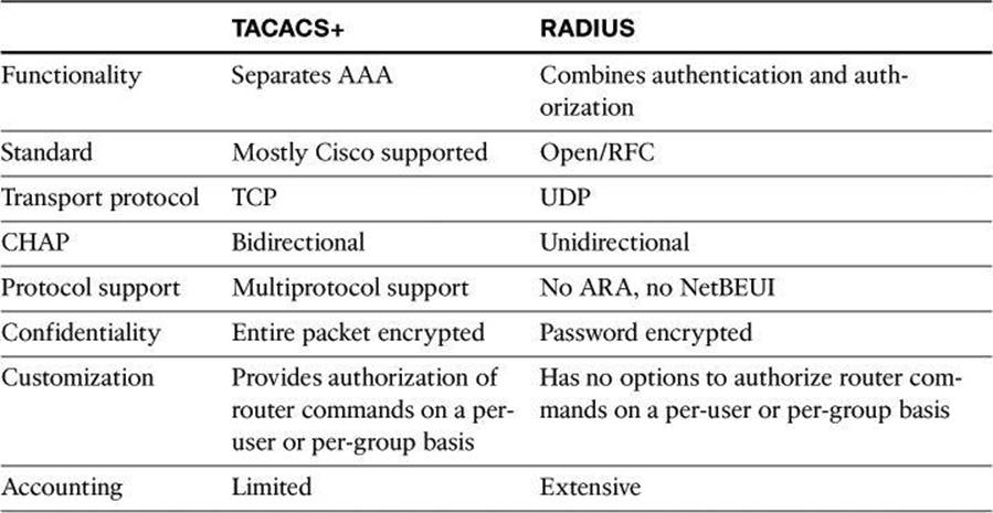
• Functionality: TACACS+ separates AAA functions according to the AAA architecture, allowing modularity of the security server implementation. RADIUS combines authentication and authorization, but separates accounting, thus allowing less flexibility in implementation than TACACS+.
• Standard: TACACS+ is a standard that is used mostly by Cisco customers. RADIUS is an open industry standard.
• Transport protocol: TACACS+ uses TCP. RADIUS uses UDP, which was chosen for the simplification of client and server implementations; however, it makes the RADIUS protocol less robust and requires the server to implement reliability measures such as packet retransmission and timeouts.
• Challenge and response: TACACS+ supports bidirectional challenge and response as used in CHAP between two routers. RADIUS supports unidirectional challenge and response from the RADIUS security server to the RADIUS client.
• Protocol support: TACACS+ provides more complete dialup and WAN protocol support. RADIUS does not support AppleTalk Remote Access (ARA), NetBIOS Extended User Interface (NetBEUI), NetWare Access Server Interface (NASI), and X.25 packet assembler/disassembler (PAD) connections.
• Confidentiality: TACACS+ encrypts the entire packet body of every packet. RADIUS encrypts only the password attribute portion of the Access-Request packet, which makes TACACS+ more secure.
• Customization: The flexibility that is provided in the TACACS+ protocol allows many things to be customized on a per-user basis or per-group basis, including which commands a user can execute on a router. RADIUS lacks this flexibility, and therefore many features that are possible with TACACS+ are not possible with RADIUS.
• Accounting: TACACS+ accounting includes a limited number of information fields. RADIUS accounting can contain more information than TACAS+ accounting records, which is the key strength of RADIUS over TACACS+.
AAA on a Cisco Router Using an External Database
Previously in this chapter, you learned how to configure a Cisco router to perform local AAA authentication and authorization. Now let’s see how to configure the Cisco router to perform external AAA authentication, authorization, and accounting. By the way, AAA accounting can be performed only using an external database.
Configuration Steps for AAA Using an External Database
Follow the steps presented in this section to configure a Cisco IOS router for AAA using Cisco Secure ACS as an external AAA server. Notice that the configuration is modular and object oriented, where AAA servers are tied together into AAA server groups for ease of management. This allows you to configure multiple servers that will act as backups of each other in a high-availability fashion.
The following steps follow the same configuration approach as the previous example where the local router database was used. AAA needs to be enabled globally on the router, and method lists are configured for authentication and, optionally, for authorization and accounting. When configuring Cisco Secure ACS as an external server, the primary method is TACACS+ or RADIUS, instead of the local database.
Step 1. Globally enable AAA.
Step 2. Configure AAA servers and groups.
Step 3. Enable AAA globally on the router.
Step 4. Configure authentication policies using method lists.
Step 5. (Optional) Configure authorization policies using method lists.
Step 6. (Optional) Configure accounting policies using method lists.
Step 7. Verify the AAA configuration.
Earlier, we learned how to turn on AAA globally with CCP or using the aaa new-model configuration command.
AAA Servers and Groups
The next step in our external AAA configuration, shown in Figure 4-17, is to configure AAA server objects. Navigate to Configure > Router > AAA > AAA Servers and Groups > Servers to view a snapshot of the information about the AAA servers that the router is configured to use. The IP address, server type, and other parameters are displayed for each server.
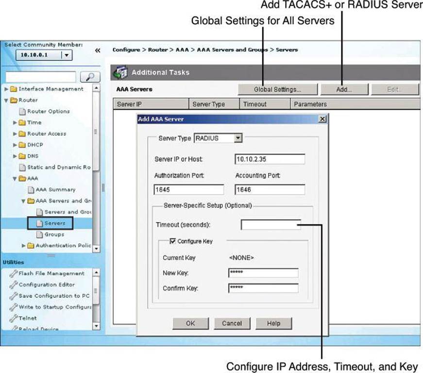
Figure 4-17. Configuring AAA Server in CCP
Click Add to add a TACACS+ or RADIUS server type, configuring the IP address for each server, as shown in Figure 4-17. You can configure timeouts and keys for TACACS+ servers, and define custom authorization and accounting ports for RADIUS servers.
The command equivalent to Figure 4-17 is as follows:
R1(config)# radius-server host 10.0.1.10 auth-port 1645 acct-port 1646 key 0 cisco
In the preceding command, cisco is the RADIUS key.
After you create the servers, you can group them into a server group. Server groups provide the opportunity to modularly combine AAA servers, just defined, in high-availability scenarios. You can add server groups, as shown in Figure 4-18, by navigating to Configure > Router > AAA > AAA Server and Groups > Groups. If you click Add to add a new group, you can choose the servers from the list and add them to the group for redundancy.
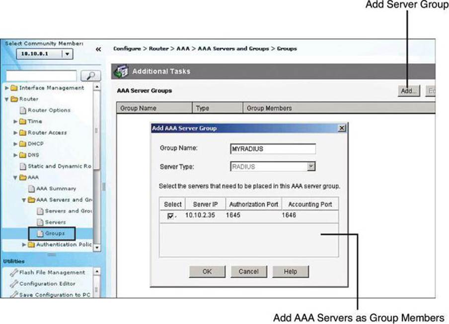
Figure 4-18. Configuring AAA Server Group in CCP
The command equivalent to Figure 4-18 is as follows:
R1(config)# aaa group server radius MYRADIUS
R1(config-sg-radius)# server 10.0.1.10 auth-port 1645 acct-port 1646
Note
In Figure 4-18, in the Add AAA Server Group dialog box, the Server Type field is grayed out. With the current version of CCP, version 2.6, only the RADIUS server group can be created. However, you can create a TACACS+ server group at the CLI with the following configuration commands:
R1(config)# aaa server group tacacs+ MYTACACS
R1(config-sg-tacacs+)# server 10.0.1.67
AAA Authentication Method Lists
The rest of the configuration follows the familiar approach of defining named method lists, or selecting the default method list, to include the AAA servers as an option for authentication, authorization, and accounting.
AAA must be enabled globally in order to define AAA method lists. To start AAA, click the button titled Enable AAA found by navigating to Configure > Router > AAA > AAA Summary. This was demonstrated earlier in Figure 4-12.
Once AAA is enabled globally, you can navigate to Configure > Router > AAA > Authentication Policies > Login and click Add to add new authentication method lists, as shown in Figure 4-19.
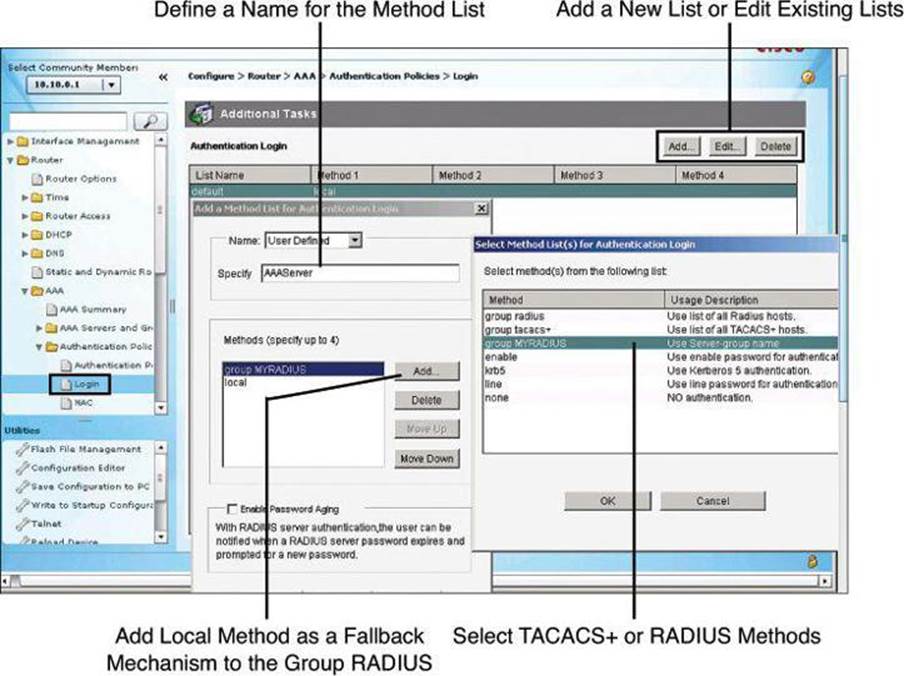
Figure 4-19. Configuring Authentication Method Lists
The command equivalent to Figure 4-19 is as follows:
R1(config)# aaa authentication login AAAServer group MYRADIUS local
Earlier in the chapter, Figure 4-14 showed the Cisco Configuration Professional window that is used to define AAA method lists and authentication methods. When using external AAA servers such as Cisco Secure ACS, you simply select TACACS+ or RADIUS server groups as your main method. It is recommended to add fallback methods, most typically the local router database, in case communication to the AAA servers fails, also shown in Figure 4-14.
AAA Authorization Policies
Authorization and accounting rules follow a similar approach using method lists to define the location of the authorization permissions and the accounting logs.
Because the TACACS+ protocol allows you to separate authentication from authorization, you can configure a router to restrict the user to be able to perform only certain functions after successful authentication. You can configure authorization for both character mode (EXEC authorization) and packet mode (network authorization).
To configure the router to use the Cisco Secure ACS server for authorization, you must create a user-defined authorization method list or edit the default authorization method list. The default authorization method list is automatically applied to all interfaces except those that have a user-defined authorization method list explicitly applied. A user-defined authorization method list overrides the default authorization method list.
Tip
To avoid locking yourself out of the router, make sure you configure authorization on the Cisco Secure ACS server before you configure the router for authorization.
Also as a precaution, consider logging on to the router console in privilege mode before starting the authorization configuration.
It is also recommended that you do not enable authorization on the backdoor port (for example, the console port) until you have appropriately confirmed the alternative authentication method, such as login via the AAA server, is working. In absence of console access, you may also simply open a second, concurrent Telnet/SSH session to confirm that you have appropriate access to the device, while still keeping the original session, used to log in, active. Once you have access to the device through the second vty session, you should save the configuration. A final resort, albeit not often desired, is to do a “reload in 5” and answer NO when asked to save the configuration. If the authentication/authorization mechanism fails, it will reload the router without saving in 5 minutes (adjustable time).
Figure 4-20 illustrates using an authorization method list for authorizing the use of the CLI with TACACS+. Notice that the local database is again used as a fallback option.
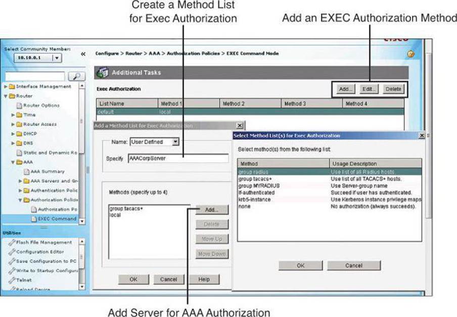
Figure 4-20. Configuring Authorization Method Lists
AAA Accounting Policies
Cisco Secure ACS serves as a central repository for accounting information, essentially tracking events that occur on the network. Each session that is established through Cisco Secure ACS can be fully accounted for and stored on the server. This stored information can be very helpful for management, security audits, capacity planning, and network-usage billing.
Like authentication and authorization method lists, method lists for accounting define the way accounting will be performed and the sequence in which these methods are performed. The default accounting method list is automatically applied to all interfaces except those that have a named accounting method list explicitly defined. A defined accounting method list overrides the default accounting method list.
AAA supports six different types of accounting: network, connection, exec, system, command, and resource.
Currently, AAA accounting can be configured only via the CLI. Interestingly, CCP v2.6 has an AAA Accounting Policies window. However, it does not have Add, Edit, and Delete buttons, so we can’t add accounting policies using the GUI. It must be done at the CLI, and even then, it still doesn’t appear in the AAA Accounting Policies window in CCP v2.6.
To configure AAA accounting using named method lists, use the commands shown in Table 4-12 while in global configuration mode.
Table 4-12. AAA Accounting Using Named Method Lists Procedure
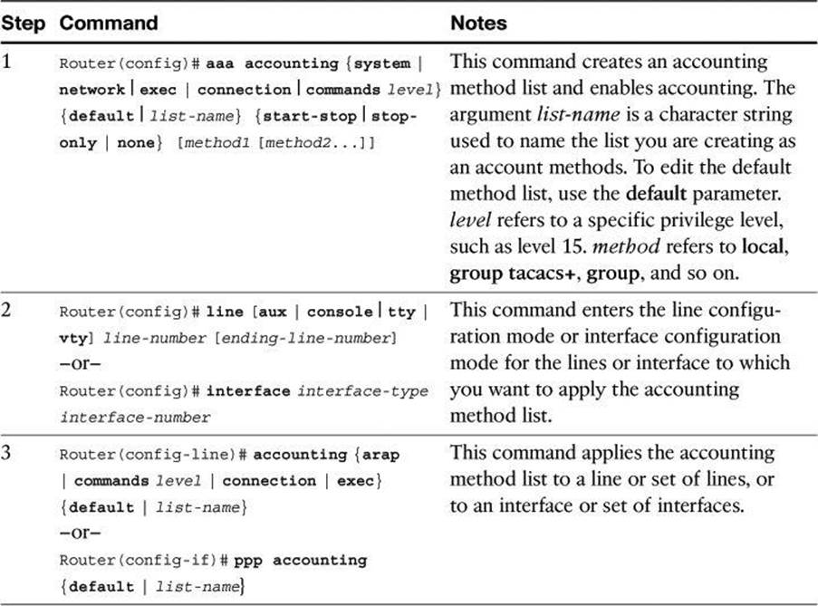
Named accounting method lists are specific to the indicated type of accounting. The AAA accounting parameters shown in Table 4-13 describe the types of accounting that can use named accounting method lists. The aaa accounting command enables you to specify how much information to record for accounting. Table 4-13 also describes the AAA accounting record types.
Table 4-13. AAA Accounting Command Parameters
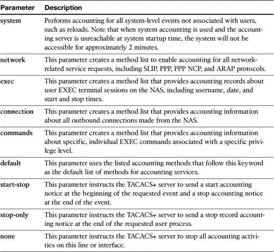
Note
System accounting provides information about all system-level events, such as when the system reboots or when accounting is turned on or off. System accounting does not use named method lists. For system accounting, you can define only the default method list.
AAA Configuration for TACACS+ Example
Example 4-12 shows the resulting running configuration of a router that has been configured for TACACS+ services using Cisco Configuration Professional and CLI commands. This example is unrelated to the RADIUS configuration we have been doing in the preceding sections.
Example 4-12. Example of AAA Configuration for TACACS+
aaa new-model
!
aaa authentication login TACACS_SERVER group tacacs+ local
aaa authorization exec default group tacacs+
aaa authorization network default group tacacs+
aaa accounting exec default start-stop tacacs+
aaa accounting network default start-stop tacacs+
aaa accounting commands 15 default stop-only group tacacs+
!
!
tacacs-server host 10.0.1.11
tacacs-server key ciscosecure
!
line vty 0 4
login authentication TACACS_SERVER
The following is an explanation of the commands displayed in Example 4-12:
• aaa new-model: Enables AAA.
• aaa authentication login TACACS_SERVER group tacacs+ local: Defines an AAA login policy entitled TACACS_SERVER that uses TACACS+ as the first authentication method and the local database as a second method if TACACS+ is unavailable. Note that the command could have been entered as aaa authentication login TACACS_SERVER tacacs+ local, but it would have appeared in the config as aaa authentication login TACACS_SERVER group tacacs+ local.
• aaa authorization exec default group tacacs+: Defines an AAA authorization policy that uses TACACS+ for access to an EXEC prompt. Note that the command could have been entered as aaa authorization exec default tacacs+, but it would have appeared in the config as aaa authorization exec default group tacacs+.
• aaa authorization network default group tacacs+: Defines an AAA authorization policy that uses TACACS+ for network access. Note that the command could have been entered as aaa authorization network default tacacs+, but it would have appeared in the config as aaa authorization network default group tacacs+.
• aaa accounting exec default start-stop group tacacs+: Defines an AAA accounting policy that uses TACACS+ for logging both start and stop records for user EXEC terminal sessions. Note that the command could have been entered as aaa accounting exec default start-stop tacacs+, but it would have appeared in the config as aaa accounting exec default start-stop group tacacs+.
• aaa accounting network default start-stop tacacs+: Defines an AAA accounting policy that uses TACACS+ for logging both start and stop records for all network-related service requests. Note that the command could have been entered as aaa accounting network default start-stop tacacs+, but it would have appeared in the config as aaa accounting network default start-stop group tacacs+.
• aaa accounting commands 15 default stop-only group tacacs+: Defines a default commands accounting method list, where accounting services are provided by a TACACS+ security server, set for privilege level 15 commands with a stop-only restriction. Note that the command could have been entered as aaa accounting commands 15 default stop-only tacacs+, but it would have appeared in the config as aaa accounting commands 15 default stop-only group tacacs+.
• tacacs-server host 10.0.1.11: Configures the IP address of the TACACS+ server.
• tacacs-server key ciscosecure: Configures an encryption key of ciscosecure to be used when communicating with the TACACS+ server.
• line vty 0 4: Enters line configuration mode for vty 0 through vty 4.
• login authentication TACACS_SERVER: Applies the AAA authentication policy named TACACS_SERVER to all five vty lines.
Troubleshooting TACACS+
Because we are still dealing with how to configure the router, let’s review the debug commands available to us. Later in this chapter, you learn the configuration that must be done on the Cisco Secure ACS server itself.
In Example 4-11, we saw the use of the debug aaa authentication command to get a high-level view of login activity. When the TACACS+ protocol is used on the router, you can also use the debug tacacs command for more detailed debugging information.
Example 4-13 shows sample output from the debug tacacs command for a TACACS+ login attempt that was unsuccessful, as indicated by the status FAIL.
Example 4-13. debug tacacs Command for an Unsuccessful TACACS+ Login Attempt
Router# debug tacacs
13:53:35: TAC+: Opening TCP/IP connection to 192.168.60.15 using source 192.48.0.79
13:53:35: TAC+: Sending TCP/IP packet number 416942312-1 to 192.168.60.15 (AUTHEN/
START)
13:53:35: TAC+: Receiving TCP/IP packet number 416942312-2 from 192.168.60.15
13:53:35: TAC+ (416942312): received authen response status = GETUSER
13:53:37: TAC+: send AUTHEN/CONT packet
13:53:37: TAC+: Sending TCP/IP packet number 416942312-3 to 192.168.60.15 (AUTHEN/
CONT)
13:53:37: TAC+: Receiving TCP/IP packet number 416942312-4 from 192.168.60.15
13:53:37: TAC+ (416942312): received authen response status = GETPASS
13:53:38: TAC+: send AUTHEN/CONT packet
13:53:38: TAC+: Sending TCP/IP packet number 416942312-5 to 192.168.60.15 (AUTHEN/
CONT)
13:53:38: TAC+: Receiving TCP/IP packet number 416942312-6 from 192.168.60.15
13:53:38: TAC+ (416942312): received authen response status = FAIL
13:53:40: TAC+: Closing TCP/IP connection to 192.168.60.15
To display information from the TACACS+ helper process, use the debug tacacs events command in privileged EXEC mode. To disable debugging output, use the no form of this command.
Note
Use the debug tacacs events command with caution, because it can generate a substantial amount of output.
Also, because console ports communicate at 9600 bauds, it is recommended to send debug output to the syslog server and enter no logging console on the router.
Example 4-14 shows sample output from the debug tacacs events command. The example shows the opening and closing of a TCP connection to a TACACS+ server, the bytes read and written over the connection, and the TCP status of the connection.
Example 4-14. debug tacacs events Command Output
Router# debug tacacs events
%LINK-3-UPDOWN: Interface Async2, changed state to up
00:03:16: TAC+: Opening TCP/IP to 192.168.58.104/1049 timeout=15
00:03:16: TAC+: Opened TCP/IP handle 0x48A87C to 192.168.58.104/1049
00:03:16: TAC+: periodic timer started
00:03:16: TAC+: 192.168.58.104 req=3BD868 id=-1242409656 ver=193 handle=0x48A87C
(ESTAB)
expire=14 AUTHEN/START/SENDAUTH/CHAP queued
00:03:17: TAC+: 192.168.58.104 ESTAB 3BD868 wrote 46 of 46 bytes
00:03:22: TAC+: 192.168.58.104 CLOSEWAIT read=12 wanted=12 alloc=12 got=12
00:03:22: TAC+: 192.168.58.104 CLOSEWAIT read=61 wanted=61 alloc=61 got=49
00:03:22: TAC+: 192.168.58.104 received 61 byte reply for 3BD868
00:03:22: TAC+: req=3BD868 id=-1242409656 ver=193 handle=0x48A87C (CLOSEWAIT)
expire=9
AUTHEN/START/SENDAUTH/CHAP processed
00:03:22: TAC+: periodic timer stopped (queue empty)
00:03:22: TAC+: Closing TCP/IP 0x48A87C connection to 192.168.58.104/1049
00:03:22: TAC+: Opening TCP/IP to 192.168.58.104/1049 timeout=15
00:03:22: TAC+: Opened TCP/IP handle 0x489F08 to 192.168.58.104/1049
00:03:22: TAC+: periodic timer started
00:03:22: TAC+: 192.168.58.104 req=3BD868 id=299214410 ver=192 handle=0x489F08
(ESTAB)
expire=14 AUTHEN/START/SENDPASS/CHAP queued
00:03:23: TAC+: 192.168.58.104 ESTAB 3BD868 wrote 41 of 41 bytes
00:03:23: TAC+: 192.168.58.104 CLOSEWAIT read=12 wanted=12 alloc=12 got=12
00:03:23: TAC+: 192.168.58.104 CLOSEWAIT read=21 wanted=21 alloc=21 got=9
00:03:23: TAC+: 192.168.58.104 received 21 byte reply for 3BD868
00:03:23: TAC+: req=3BD868 id=299214410 ver=192 handle=0x489F08 (CLOSEWAIT)
expire=13
AUTHEN/START/SENDPASS/CHAP processed
00:03:23: TAC+: periodic timer stopped (queue empty)
Note
The TACACS messages are intended to be self-explanatory to IT service personnel only.
Deploying and Configuring Cisco Secure ACS
Cisco Secure ACS uses a modular approach to define AAA policies. Cisco Secure ACS 5.2 offers a new paradigm. In previous versions of ACS, the policy is group based. A user inherits network privileges and restrictions based on the group to which the user belongs. As an example, Mary from Marketing is limited to a single remote-access session, while Indy from IT is provided with up to three concurrent remote-access sessions. ACS 5.2 provides much more granular policies with its rule-based approach (not to be confused with Role-Based CLI Access). With rules-based policies, the ACS 5.2 looks at the environment used by the user: for example, the user is Indy, connecting at 2:45 p.m., from network device Switch B, port 19, and so forth. So, ACS 5.2 looks at not only who the user is, but also from which network device the user’s session is initiating, what time of day the user is connecting, and so forth. In the next two sections, we will examine how prior versions of Cisco Secure ACS operate, and then we will see how the new ACS 5.2 works.
Evolution of Authorization
Cisco made a significant change in authorization when it introduced Cisco ACS 5.2
Before: Group-Based Policies
As mentioned, earlier versions of Cisco Secure ACS base policy on membership in user groups. The user groups define the access restrictions and permissions for the users who are members of the group.
Using the group-based approach, as shown in Figure 4-21, when a user requests access, the credentials of the user are authenticated with an identity store. Once authenticated, the user is associated with the appropriate user group. The authorization rules in this environment are part of the group itself, including restrictions such as time of day or point of access into the network.
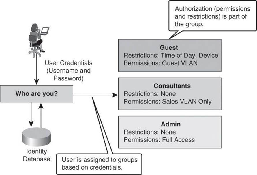
Figure 4-21. Previous Version of Cisco Secure ACS Using Group-Based Policies
Using group-based policies, permissions are set based primarily on the identity-based association of a user with a single group. Because authorization is tied to the user group, all members of the user group have the same access restrictions and permissions all the time.
This type of authorization is suitable for simple policies, in which identity is the dominant or only condition, but it results in lack of flexibility in the presence of other requirements or conditions that define the permissions of the user.
The trends in network connectivity today call for universal access from multiple locations, at multiple times, using multiple devices, as exemplified in Figure 4-22. For example, you might want to grant an employee full access when they are on campus, but restricted access when they are working remotely over the weekend. The group-based policy approach results in complex access policies and rules because you must consider the user’s choice of device (laptop versus PDA), the security posture of the device at the time of connection, and many other conditions.
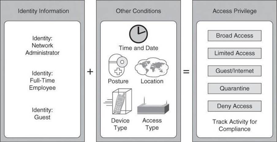
Figure 4-22. Complexity of a Mobile Workforce and Borderless Networks
Now: More Than Just Identities
To manage situations such as those shown in Figure 4-22, a different approach is needed—one that grants permissions on conditions other than identity alone. Using Cisco Secure ACS, starting with version 5.x, group-based policies are replaced by rule-based policies, which provide a more flexible approach that can match the variety of access conditions that are found in current networks.
Using the rule-based approach, instead of relying on the group to contain all the information, identity classification is separated from other conditions or restrictions, as shown in Figure 4-23. Permissions are also decoupled from the group, resulting in the group acting as an identity classification only and no longer containing access permissions and restrictions.
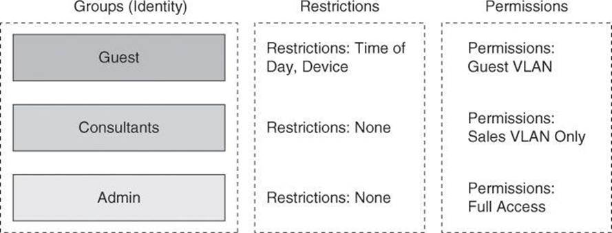
Figure 4-23. New in Cisco Secure ACS 5.2: Rule-Based Policies
In addition to an expanded concept of identity, which is defined by the users and group membership, the idea of restrictions was also expanded to consider other session and environment attributes, such as access location, access type, time, date, end-station health, and so forth.
These attributes become a contextual set of conditions that determines which permissions to apply to the network access request. In other words, the previous approach of associating permissions directly at the user and group level is replaced by a new approach in which the permissions are a separate object called an authorization profile. In addition, contextual conditions can be evaluated separately, eventually resulting in different sets of permissions for the same user, based on the different access conditions presented in Figure 4-24.
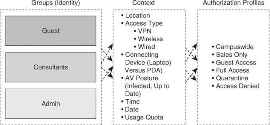
Figure 4-24. Context-Aware Authorization Profiles
Dynamic Access Policies on Cisco ASA
For those readers familiar with Cisco ASA, you will relate Figure 4-24 to the dynamic access policies (DAP) used in VPN settings, where the ASA assigns a policy to an incoming connection based on many criteria, including not only the user’s identity, but also how the computer is used to connect, whether the computer is a corporate asset, whether the computer has antivirus protection, and so forth.
Rule-Based Policies
Authorization is now determined using a set of logical rules, which resemble the structure of if-then-else conditions, that better match the variety of network access conditions and resulting permissions. Figure 4-25 illustrates this logic. If access conditions match a certain set of attributes for the user or group, then apply a set of permissions. Using rule-based policies, the conditions can be any combination of available session attributes, including, but certainly not limited to, identity.
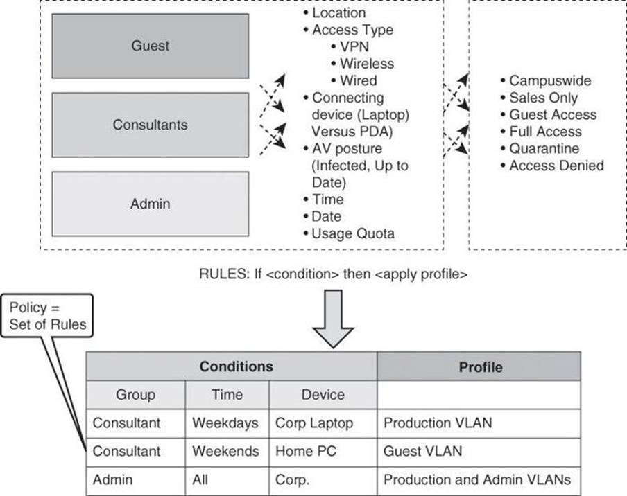
Figure 4-25. Rule-Based Policies with Cisco Secure ACS 5.2
As previously mentioned, the permissions in Cisco Secure ACS v5.x are defined in another modular object known as an authorization profile. Several profiles can be created, and multiple sets of conditions can arrive at the same profile. For instance, a user can acquire the Guest role if the user does not exist in the identity database, but a user can also acquire this role if the user is valid but tries to access the network from an unknown location, using a smartphone, over the weekend.
Authorization profiles can contain permissions in multiple dimensions; for instance, VLANs, downloadable ACLs (dACL), quality of service (QoS) settings, RADIUS attributes, and others.
The example in Figure 4-25 highlights the flexibility of the rule-based policies. Notice that a single classification of users can get different authorizations based on more than just the identity attribute. The benefits of this are that the rule conditions can be any combination of the access session attributes, and that the assignment of permissions does not have to be based on a specific identity at all. It is a set of conditions, including identity, that defines access control.
Configuring Cisco Secure ACS 5.2
Configuration of Cisco Secure ACS 5.2 will be explained using the following scenario, illustrated in Figure 4-26, which focuses on authorization policies for device administration. In our scenario, Cisco Secure ACS will be used as the policy server to grant the admin user full access to the router CLI, at privilege level 15. Similarly, the monitor user will obtain privilege level 1 for read-only access to the router’s CLI. The system uses TACACS+ between the router and the policy server. Obviously, this scenario does not present the full potential of Cisco Secure ACS 5.x, which is beyond the scope of this book. The goal in this book, which focuses on Cisco IOS security, is to show you a basic configuration of Cisco Secure ACS 5.2 when it is configured for basic interaction with your network devices.
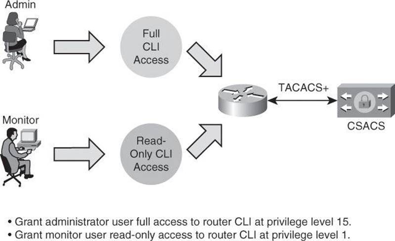
Figure 4-26. Rule-Based Policies Scenario
Configuring Authorization Policies for Device Administration
The rules-based approach is easily configured using the Cisco Secure ACS GUI. The following steps are required to build a device administration access policy using Cisco Secure ACS 5.2. This policy will define the type of CLI access that different user roles have to a router or group of routers.
The general steps used to configure Cisco Secure ACS for device administration are as follow:
Step 1. Add network devices to Cisco Secure ACS so the router appears as an AAA client.
Step 2. Define identity groups and identity the store.
Step 3. Configure access services to process requests.
Step 4. Create the identity policy.
Step 5. Create the authorization policy.
Adding Network Devices to Cisco Secure ACS
The first step in adding a network device to Cisco Secure ACS is to define network device groups and add routers and network devices to the groups. This step allows Cisco Secure ACS to know which devices will send AAA requests.
In Cisco Secure ACS, you can define network device groups (NDG), which are sets of devices. These NDGs provide logical grouping of devices—for example, by device location or type—which you can use in policy conditions, as shown in Figure 4-27.
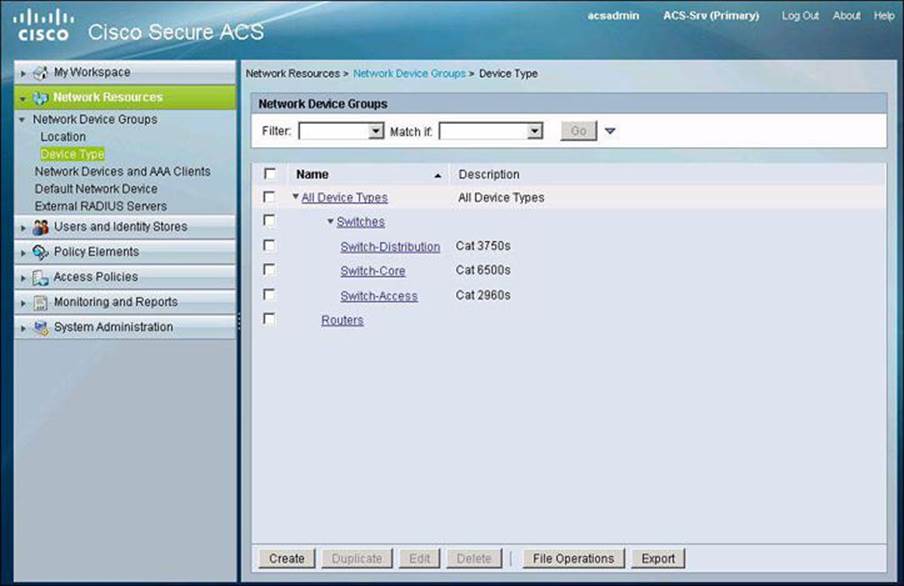
Figure 4-27. Cisco Secure ACS and the Logical Grouping of Devices
When Cisco Secure ACS receives a request for a device, the NDGs that are associated with that device are retrieved and compared against those in the policy table. With this method, you can group multiple devices and assign them the same policies. For example, you can group all devices in a specific location and assign to them the same policy.
The device group hierarchy is the hierarchical structure that contains the NDGs. The hierarchy provides further flexibility to create groups of devices that follow a functional classification, in addition to a geographic or location-based classification.
The access the configuration options for this step, navigate to Network Resources > Network Device Groups in the menu on the left side of the screen. As you can see in Figure 4-27, there are two types of NDG: one based on location and one based on device type. In this example, we are creating device type groups.
Figure 4-28 illustrates the task of adding a network device to a group under Network Resources > Network Devices and AAA Clients. The network device definition can be associated with a specific IP address or a subnet mask, where all IP addresses within the subnet can access the network. The device definition includes the association of the device to NDGs. You also configure here whether the device uses TACACS+ or RADIUS.
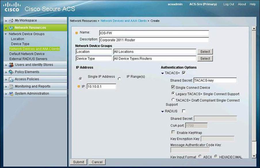
Figure 4-28. Adding Network Devices to Cisco Secure ACS
Defining Users, Identity Groups, and Internal Identity Stores
The second step is to define the user and identity stores. In our scenario, the internal Cisco Secure ACS store is used to validate users and credentials. The next step, then, is to define users and groups in the local Cisco Secure ACS database. This can be accomplished by navigating to Users and Identity Stores > Internal Identity Stores > Users and clicking Create to add a new user, as illustrated in Figure 4-29. This figure shows the creation of a new user in the internal identity store. The user is assigned to an existing group.
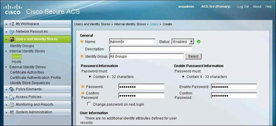
Figure 4-29. Creating Users in Identity Store
Configuring Access Services
The third step is to configure the access services that will define the CLI access policy. In Cisco Secure ACS 5.x, a policy is a set of rules that the server uses to evaluate an access request and return a decision. Cisco Secure ACS 5.x organizes the sequence of independent policies (a policy workflow) into an access service, which it uses to process an access request. You can create multiple access services to process different kinds of access requests, such as for device administration or network access.
When you create an access service, you define the type of policies and policy structures that it contains; for example, policies for device administration or network access, as shown in Figure 4-30. The default access services use and match RADIUS for network access policies, while using and matching TACACS+ for device administration policies. This means that, in this example, there is no need to change the default settings; we are using TACACS+ as the AAA protocol between the router and the Cisco Secure ACS server.
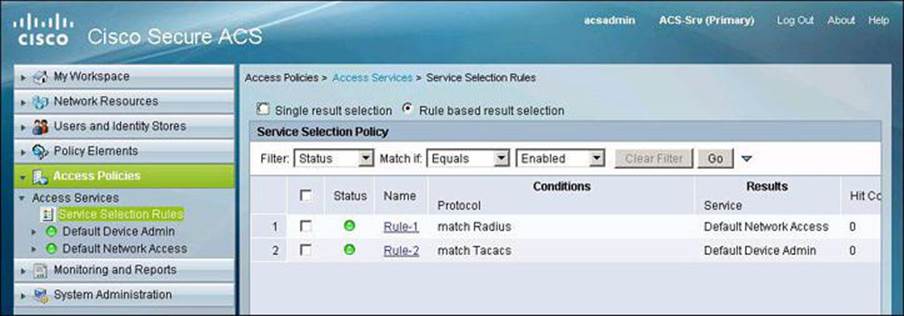
Figure 4-30. Configuring Access Services
Configuring the Identity Policy
The fourth step is to configure the identity policy, which defines how requests are authenticated. The navigation path for this option is Access Policies > Access Services > Default Device Admin > Identity. In our scenario, the access service uses the local Cisco Secure ACS store for router device administration. This means that the Default Device Admin Access Service is to be configured with the Internal Users store as an identity source, as shown in Figure 4-31. This is also the default setting. Other options include external databases, such as LDAP and Active Directory.
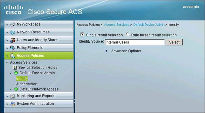
Figure 4-31. Configuring Identity Policy
Configuring the Authorization Policy
The fifth step configures the authorization policy, which defines the actual rules for Role-Based CLI Access and device administration, in our scenario shown in Figure 4-32. The navigation path is Access Policies > Access Services > Default Device Admin > Authorization. You then click Create to add a new authorization policy.
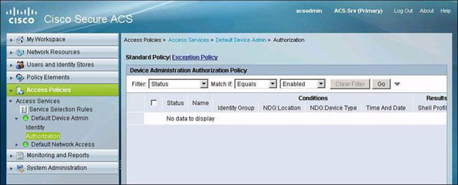
Figure 4-32. Configuring Authorization Policy
Notice the familiar framework of policies that are based on a set of conditions and a profile to apply if those conditions match an access request.
When you create an access service and select a service policy structure for Device Administration, ACS automatically creates a shell/command authorization policy. You can then create and modify policy rules.
The web interface supports the creation of multiple command sets for device administration. With this capability, you can maintain a smaller number of basic command sets. You can then choose the command sets in combination as rule results, rather than maintaining all the combinations themselves in individual command sets.
Figure 4-33 illustrates the creation of an authorization rule for the admin user. Notice the Conditions section, where you can define the matching conditions that would trigger the policy (in this example, membership to the Admin group and an NDG of Routers). Also notice the Results section, with its corresponding Select button. This option allows you to create customized tasks or attributes to be granted to user admin. In this example, we configure a privilege level 15 for this user.
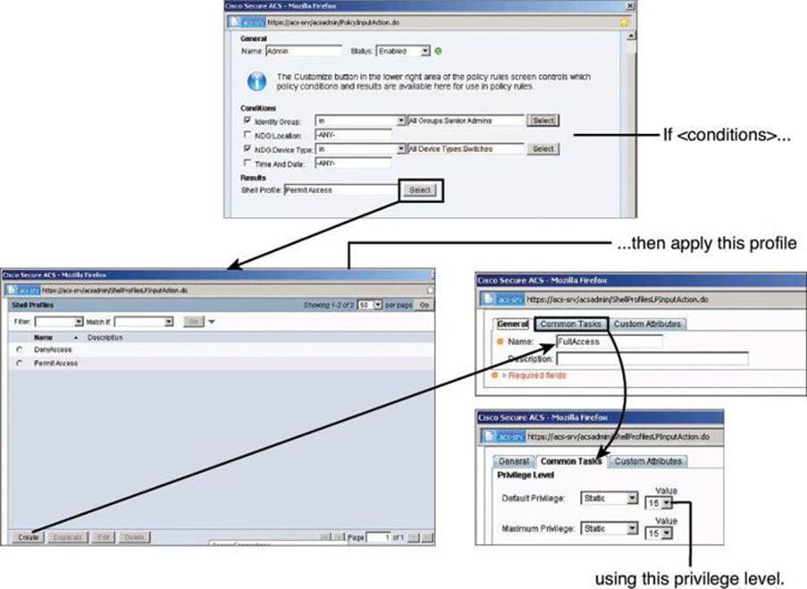
Figure 4-33. Configuring an Authorization Rule for Admin User
Figure 4-34 shows the final configuration of authorization policies for both users: Admin, obtaining the shell profile FullAccess, which grants privilege level 15, and Monitor, obtaining the shell profile ReadOnly, which grants privilege level 1.
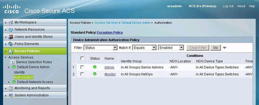
Figure 4-34. Final Configuration of Authorization Policies for Users
Summary
The following topics were discussed in this chapter:
• Role-based access control, use of strong authentication and cryptography, and deployment of NTP are among the recommended practices in secure management and reporting.
• Role-based access control can be accomplished on the router CLI using views.
• Syslog and SNMP provide management notification options for Cisco routers.
• AAA services can use the local router database or a remote AAA server database.
• Method lists provide redundancy and fallback options for AAA configuration using Cisco Configuration Professional.
• CLI commands can be used to verify the correct configuration of the router.
• Cisco Secure ACS can be used as an external AAA database for authentication, authorization, and accounting.
• Two popular AAA protocols, TACACS+ and RADIUS, can be used by network devices to communicate with an external AAA server.
• AAA deployment can be completed by configuring network elements to use AAA authentication and authorization.
References
For additional information, refer to these resources:
Cisco.com Resources
“Cisco Configuration Professional,” http://www.cisco.com/go/ccp
“Cisco ISE Fundamentals,” http://www.cisco.com/en/US/prod/collateral/vpndevc/ps5712/ps11637/ps11195/ise_fundamentals.html
“Cisco Secure Access Control System,” http://www.cisco.com/go/acs
“Password Recovery Procedures,” http://www.cisco.com/en/US/products/sw/iosswrel/ps1831/products_tech_note09186a00801746e6.shtml
User Guide for the Cisco Secure Access Control System 5.2, http://www.cisco.com/en/US/docs/net_mgmt/cisco_secure_access_control_system/5.2/user/guide/acsuserguide.html
RFCs
RFC 1305, “Network Time Protocol (Version 3) Specification, Implementation and Analysis,” http://www.faqs.org/rfcs/rfc1305.html
RFC 2571, “An Architecture for Describing SNMP Management Frameworks,” http://www.ietf.org/rfc/rfc2571.txt
Secure Shell
Wikipedia. “Secure Shell,” http://en.wikipedia.org/wiki/Secure_Shell
Review Questions
Use the questions here to review what you learned in this chapter. The correct answers are found in the Appendix, “Answers to Chapter Review Questions.”
1. Which port is used by NTP?
a. UDP 49
b. TCP 69
c. UDP 123
d. TCP 1211
2. Which two statements are true about passwords?
a. The console port does not require a password for initial console administrative access.
b. Passwords cannot include symbols and spaces.
c. You can use either the enable password or the enable secret password to enter the enable mode when both are configured on a router.
d. The enable secret password is always hashed inside the router configuration using a MD5 hashing algorithm.
3. What is the purpose of the 5 in the following command: username Admin secret 5 $1$feb0$a104Qd9UZ./Ak00KTggPD0?
a. The encrypted password will be converted to cleartext in the running configuration using MD5.
b. The user Admin has privilege level 5 in this router.
c. The user Admin has five attempts to log in to this router.
d. The encrypted-secret password was hashed with MD5.
4. What is the purpose of the command parser view?
a. It creates different views of router configuration for different users.
b. It provides a root view of all commands.
c. It configures a password for a view.
d. It is used to enter commands accessible for that view.
5. Which command would you use to enable Cisco IOS resilience?
a. secure boot-ios
b. secure boot-config
c. secure boot-image
d. secure boot-flash
6. Which command is used to enable AAA on a router?
a. aaa enable
b. aaa authentication new-model
c. aaa tacacs+
d. aaa new-model
7. Which of the following is not supported by Cisco Secure ACS?
a. StreetTalk Directory Services
b. Directory Services
c. One-time passwords
d. ODBC databases
8. Which portion of a RADIUS packet is sent in plaintext?
a. All portions
b. All portions except for the password
c. All portions except for the CHAP password
d. All portions except for the username
9. Which of the following protocols is automatically enabled once RSA keys have been generated?
a. Telnet
b. SDM
c. SSH
d. HTTPS
10. What is significantly different with Cisco Secure ACS 5.x compared to an older version of Cisco Secure ACS?
a. Users are authenticated locally but authorized on a remote AAA server.
b. Permissions are granted on conditions other than identity alone.
c. The desktop is first checked against a set of policies prior to presenting the user with a login prompt.
d. Different users can share one single AAA policies.