EnCase Computer Forensics (2012)
Chapter 1
Computer Hardware
EnCE Exam Topics Covered in This Chapter:
· Computer hardware components
· The boot process
· Partitions
· File systems
Computer forensics examiners deal most often with the media on which evidentiary data is stored. This includes, but is not limited to, hard drives, CDs, DVDs, flash memory devices, smart phones, tablets, and even legacy floppies and tapes. Although these devices might be the bane of the examiner’s existence, media devices don’t exist in a void, and knowledge of a computer’s various components and functions is a must for the competent examiner.
As an examiner, you may be called upon to explain how a computer functions to a jury. Doing so requires you know a computer’s function from a technical standpoint and that you can translate those technical concepts into real-world, easy-to-understand terms.
As an examiner, you may also be subjected to a voir dire examination by opposing counsel to challenge your competence to testify. Acronyms are hardly in short supply in the field of computing—some well-known and meaningful, others more obscure. Imagine being asked during such an examination to explain several of the common acronyms used with computers, such as RAM, CMOS, SCSI, BIOS, and POST. If you were to draw a blank on some obscure or even common acronym, picture its impact on your credibility.
You may encounter problems with a computer system under examination or with your own forensic platform. Troubleshooting and configuration require knowledge of the underlying fundamentals if you are to be successful.
Thus, the purpose of this chapter is to provide you with a solid understanding of the various components of a computer and show how a single spark of electricity brings those otherwise dead components to life through a process known as booting the computer. In addition, you’ll learn about the drive partitions and file systems used by computer systems.
Computer Hardware Components
Every profession has, at its core, a group of terms and knowledge that is shared and understood by its practitioners. Computer forensics is certainly no exception. In this section, I discuss the various terms used to describe a computer’s components and systems.
Case The case, or chassis, is usually metal, and it surrounds, contains, and supports the computer system components. It shields electrical interference (both directions) and provides protection from dust, moisture, and direct-impact damage to the internal components. It is sometimes erroneously called the central processing unit (CPU), which it is not.
Read-Only Memory (ROM) This is a form of memory that can hold data permanently, or nearly so, by virtue of its property of being impossible or difficult to change or write. Another important property of ROM is that it is nonvolatile, meaning the data remains when the system is powered off. Having these properties (read-only and nonvolatile) makes ROM ideal for files containing start-up configuration settings and code needed to boot the computer (ROM BIOS).
Random Access Memory (RAM) A computer’s main memory is its temporary workspace for storing data, code, settings, and so forth. It has come to be called RAM because it exists as a bank of memory chips that can be randomly accessed. Before chips, tape was the primary media, and accessing tape was—and still is—a slow, linear or sequential process. With the advent of chips and media on drives (both floppy and hard drives), data could be accessed randomly and directly and therefore with much greater speed. Hence, random access memory was the name initially given to this type of memory to differentiate from its tape predecessor. Today most memory can be accessed randomly, and the term’s original functional meaning, differentiating it from tape, has been lost to history. What distinguishes RAM from ROM, among other properties, is the property known as volatility. RAM is usually volatile memory, meaning that upon losing power, the data stored in memory is lost. ROM, by contrast, is nonvolatile memory, meaning the data remains when the power is off. It is important to note, however, that there are nonvolatile forms of RAM memory known as nonvolatile random access memory (NVRAM), and thus you should not be quick to assume that all RAM is nonvolatile.
![]()
The computer forensic examiner, more often than not, encounters computers that have been shut down, seized, and delivered for examination. Important information in RAM (the computer’s volatile memory) is lost when the computer’s plug is pulled. All is not lost, however, because this data is often written to the hard drive in a file called the swap file. This swap file, in its default configuration, can grow and shrink in most Microsoft Windows systems, which means this data can be in the swap file itself, as well as in unallocated clusters and in file slack as the swap file is resized. Unallocated clusters and file slack are areas containing data that is no longer in an allocated file. I’ll cover them in detail in Chapter 2. What’s more, if the computer was in the hibernate mode, the entire contents of RAM are written to a file named hiberfil.sys so that the contents of RAM can be restored from disk. In fact, the system can be restored in the time it takes to read the hiberfil.sys file into RAM. It should be no surprise to learn that the hiberfil.sys file is the same size as the system’s RAM memory size!
Power Supply The power supply transforms supply voltage (120VAC or 240VAC) to voltages and current flows required by the various system components. DC voltages of 3.3 volts, 5 volts, and 12 volts are provided on a power supply for an ATX form factor motherboard.
![]()
The standard molex power connector used frequently by examiners has four wires providing two different voltages (yellow = 12VDC+, black = ground, black = ground, red = 5VDC+).
Motherboard or Mainboard This component is the largest printed circuit card within the computer case. It is mounted on “stand-offs” to raise it above the case, providing a space for airflow and preventing contact or grounding of the printed circuits with the case. The motherboard typically contains the following: the CPU socket, BIOS, CMOS, CMOS battery, Real-Time Clock (RTC), RAM memory slots, Integrated Drive Electronics (IDE) controllers, Serial Advanced Technology Attachment (SATA) controllers, Universal Serial Bus (USB) controllers, floppy disk controllers, Accelerated Graphics Port (AGP) or Peripheral Component Interconnect (PCI) Express video slots, PCI or PCI Express expansion slots, and so forth. Many features that once required separate expansion cards are now offered onboard, such as Small Computer System Interface (SCSI) controllers, network interface (Gigabit Ethernet and wireless), video, sound, and FireWire (1394a and b).
Microprocessor or CPU The brains of the unit, the CPU is a massive array of transistors arranged in microscopic layers. The CPU performs data processing, or interprets and executes instructions. Accordingly, most of the computer’s function and instructions are carried out in this unit. Modern processors generate enormous amounts of heat, and quickly and efficiently eliminating heat is essential to both the function and survival of the component.
Heat Sink and Fan At the very least, a heat sink and fan will be attached to the CPU to keep it cool. The heat sink interfaces directly with the CPU (or other heat-generating chip), usually with a thermal compound sandwiched between. The heat sink consists of a high-thermal conductance material whose job it is to draw the heat from the chip and to dissipate that heat energy into the surrounding air (with the assistance of the fan, with an array of cooling fins). Some high-end platforms will have thermal solutions (heat sinks and fans) mounted to RAM memory, chipsets, hard drives, and video cards. Water-cooling systems are becoming more popular with gamers. Use caution working around these systems because water and electricity are usually at odds; therefore, damage to systems can occur.
Hard Drive This is the main storage media for most computer systems; it holds the boot files, operating system files, programs, and data. It consists of a series of hard thin platters revolving at speeds ranging from 4,800 to 15,000 revolutions per minute (RPM). These platters (which are magnetized) are accessed by heads moving across their surfaces as they spin. The heads can read or write, detecting or creating microscopic changes in polarity, with positive changes being 1s and negative changes being 0s—which is why we refer to the binary system of “1s and 0s.”
Hard drive platters have an addressing scheme so that the various locations where data is stored can be located for reads and writes. Originally this addressing scheme involved the CHS system (C = Cylinder, H = Head, and S = Sector). A sector is the smallest amount of space on a drive that can be written to at a time. A sector contains 512 bytes that can be used by the operating system. Each side of the platter is formatted with a series of concentric circles known as tracks. Sectors are contained in the tracks, and originally each track contains the same number of sectors. A cylinder is a logical construct; it is a point on all the platters where the heads align along a vertical axis passing through the same sector number on all the platters. There are two heads for each platter, one for each side (side 0 and side 1). Depending on the number of platters present, the heads will be numbered. To determine the number of bytes present on a hard drive, a formula is used: C n H n S n 512 = total storage bytes. The C is the total number of cylinders, the H is the total number of heads, the S is the number of sectors per track, and 512 is a constant that represents the number of bytes in a sector usable by the operating system (OS).
This formula holds true as long as the number of sectors per track remains the same for all tracks, which applies to older, lower-capacity hard drives. This system, however, has limitations for hard drive storage capacity. The limitations reflect how densely populated (sectors per track) the inner tracks are. The outer tracks, by contrast, can always hold more data than the inner tracks and contain wasted storage space. To overcome this limitation, Zoned-Bit Recording (ZBR) was developed; in ZBR, the number of sectors per track varies in zones, with the outer zones containing more sectors per track than the inner zones. This system has vastly improved data storage capacities.
The formula, however, is not valid for modern drives, because the number of sectors per track is no longer constant if ZBR is present. To address the larger-capacity hard drives, a new addressing scheme has been developed, called Logical Block Addressing (LBA). In this system, sectors are addressed simply by sector number, starting with sector zero, and the hard drive’s electronics translate the sector number to a CHS value understood by the drive. To determine the storage capacity of hard drives using ZBR, you determine the total LBA sectors and multiply that number by 512 (bytes per sector). The product yields the total storage capacity of the drive in bytes (total LBA sectors n 512 = total storage capacity in bytes).
Depending on their electrical interface or controller, hard drives can be Advanced Technology Attachment (ATA), which is now often called PATA to differentiate parallel from serial with the advent of SATA; SATA (Serial ATA); or SCSI.
Solid State Drive (SSD) SSDs do away with moving parts altogether, and all data is stored, currently, on NAND memory chips of the same type found in USB thumb drives. This data is persistent and is therefore dubbed nonvolatile. You may also encounter a hybrid drive that is a traditional hard drive (spinning magnetic platter storage) with an SSD. These drives attempt to combine the advantages of both types of drives into one drive. SSD drives are rapidly evolving in terms of speed and storage capacity. As of 2011, you will find them mostly in portable computing devices, but in time, they will become mainstream storage devices in desktop computers as well. SSDs have several different form factors. You may find them in standard hard disk drive (HDD) housings for compatibility with existing technologies. You may find them in a boxed format designed to fit a rack mount system. You may also find them in various bare board form factors to install via a connector to the motherboard. Finally, you may find them in a ball grid array in which the memory chips are soldered directly onto the system motherboard. The latter saves space and energy and will no doubt be used more often in the future. To further complicate matters, the various form factors employ various types of connectors, including SATA, mini-SATA, proprietary connections, and direct solder connections.
Small Computer Systems Interface (SCSI) SCSI is an electronic interface that originated with Apple computer systems and migrated to other systems. It is a high-speed, high-performance interface used on devices requiring high input/output, such as scanners and hard drives. The SCSI BIOS is an intelligent BIOS that queues read/write requests in a manner that improves performance, making it the choice for high-end systems. SCSI drives do not use the master-slave pin configurations of the IDE counterparts. Rather, they are assigned ID numbers that are most often set by pinning jumpers.
Integrated Drive Electronics (IDE) Controller IDE is a generic term for any drive with its own integrated drive controller. Originally there were three types, but only one survived; it is known as Advanced Technology Attachment (ATA). Officially, the IDE interface today is called ATA, and the two names will often be used interchangeably. Two IDE connectors are found on the motherboard, one labeled primary IDE and the other secondary IDE. Each is capable of handling two IDE devices (hard drive, CD, DVD), for a maximum of four IDE devices. Of the two devices on the same IDE ribbon cable, one is the master, and the other is the slave. One places jumpers on pins to designate the master or slave status. Typically the boot hard drive will be attached to the primary controller, and it is the master if two devices are present on that IDE channel. Alternatively, you could use the Cable Select (CS) method of pinning by which the assignment of master-slave is done automatically, provided you use a cable that properly supports CSEL (another way of abbreviating Cable SELect) signaling. On an 80-conductor IDE/ATA cable using CS, the drive at the end of the cable will be assigned as master, and the drive assigned to the middle connector will be the slave.
Serial Advanced Technology Attachment (SATA) controller By the beginning of this century, IDE (ATA) hard drives had been around for a long time, but the electronic circuitry by which the data was sent had reached its upper limit (133 megabytes per second, or MBps). In August 2001, a new standard, known as SATA 1.0, was finalized and approved. SATA uses serial circuitry, which allows data to be sent, initially, at 150 MBps. SATA II standards, released on October 2002, have found their way into the market, with SATA II drives now delivering buffer-to-host transfer rates of 300 MBps. Unlike IDE drives, SATA drives require no “pinning.” SATA ports can be found on most modern motherboards, and they often have RAID 0 available to them. IDE drives are starting to disappear and are being replaced by SATA drives. Even though IDE drives are being phased out, forensic examiners can expect to see them around for a long time, because they were in use for more than 10 years.
Serial Attached SCSI (SAS) SCSI drives reached their limit as they, like their ATA drive counterparts, relied upon parallel bus technology for data transmission. As SATA replaced ATA using a serial bus technology, SAS replaced SCSI with a point-to-point serial bus technology. SAS continues to use the SCSI command set. SAS drives and tape drives are usually found in the high-end computers (servers, data centers, and so on). SAS offers backward compatibility with generation-two SATA drives, meaning you can attach a SATA drive (second generation) to an SAS backplane, but you can’t attach an SAS drive to any SATA backplane. As you might expect, SAS drives use yet another connector—several actually—all of which are much smaller than their SCSI predecessor connectors. SAS currently supports speeds of 6 Gbps, with 12 Gbps expected in late 2012.
Redundant Array of Inexpensive Disks (RAID) First I’ll clear the air on the acronym RAID. It means Redundant Array of Independent Drives (or Disks), and it is also known as Redundant Array of Inexpensive Drives (or Disks). Thus, the letter I can mean inexpensive or independent, and the letter D can mean drives or disks. But if you find yourself in an argument over this at your next geek cocktail party, don’t bet the ranch because either combination of these words is correct. A RAID is an array of two or more disks combined in such a way as to increase performance or increase fault tolerance. In a RAID 0, data is striped over two or more disks, which increases performance by reducing read and write times. However, if any disk fails in a RAID 0, all data is lost. In a RAID 1, data is mirrored over the drives in the array. A RAID 1 does not increase performance, but it does create redundant data, thereby increasing fault tolerance. In a RAID 5 configuration, typically data is stored on three drives, although other configurations can be created. Data is striped over two drives, and a parity stripe is created on the third. Should any one drive fail, it can be “rebuilt” from the data of the other two. RAID 5 achieves fault tolerance and increased performance. RAID 0 + 1 is a relatively new type of RAID. It is typically configured with four drives; one pair is used for striping data, and the other pair is a mirror of the striped pair. With this configuration, you again achieve high performance and fault tolerance. RAID 0 + 1 can also be found as RAID 1 + 0. While similar, with the former (0+1), the stripe is built before the mirror. With the latter (1+0), the mirror is built before the stripe. Rather than digress into a discussion of the performance issues of these two different configurations, over which reasonable technicians can find grounds for dispute, we’ll move on.
Floppy Drive Floppy drives used to be primary storage devices. Currently they are used to store and move small amounts of data, since the capacity of the 3.5-inch floppy is only 1.44 MB of data. Forensic examiners often use them as boot drives to boot systems for DOS acquisitions, which is a method of acquiring data using a DOS boot disk. I’ll cover this extensively in Chapter 4. Floppy drives are being phased out in lieu of CD/DVD drives and USB thumb drives.
![]()
When going out into the field to image a system, always pack a spare internal 3.5-inch floppy drive. You may have to do a DOS acquisition, and the target system may not be equipped with a floppy drive. Or, the one present may be defective, and a CD boot may not be an option. Note that EnCase v7 retired the DOS version of EnCase (en.exe) that can load from a floppy disk. Linux EnCase (linen) is available, which uses 32-bit processing vs. only 16-bit in DOS. However, linen will not fit on a floppy disk, so a CD-ROM drive would be used.
Compact Disc - Read-Only Memory (CD-ROM) or Compact Disc - Read/Write (CD-RW) Drive CD drives use laser beams to read indentations and flat areas as 1s and 0s, respectively. The data is formatted into a continuous spiral emanating from the center to the outside. (In contrast, hard drive data is formatted into concentric circles.) CD-ROM is read-only technology, whereas CD-RW permits writing to CD media in addition to reading.
Digital Versatile Disc - Read-Only Memory (DVD-ROM) or Digital Versatile Disc - Read/Write (DVD-RW) DVD drives use a technology similar to that of CD drives. The laser beam used with DVDs is a shorter wavelength, creating smaller pits and lands, which are actually depressions and elevations in the physical surface. The result is a spiral track that is more densely populated with data. Couple this improvement with layered spiral tracks, and the gain in data storage capacity is tremendous. Whereas a CD stores, at most, approximately 700 MB of data, a DVD can hold 8 GB to 17 GB of data, with higher densities on the horizon.
USB Controller Universal serial bus (USB) is a external peripheral bus standard capable of high-speed serial input/output (USB 1.1 = 1.5 Mbps, USB 2 = 480 Mbps, and USB 3 = 5 Gbps). It was developed to facilitate Plug and Play for external devices, without the need for expansion cards and configuration issues.
USB Port This is a rectangular-shaped port connected to the USB controller, with pins for four conductors (1: cable power, 2: data negative, 3: data positive, and 4: ground—all surrounded by shielding). These ports are used for USB connections, which can be external storage devices, cameras, license dongles, keyboards, mice, and so forth.
IEEE 1394 Also known as FireWire (the name licensed by Apple) or iLink (Sony), 1394 is yet another high-speed serial I/O standard. Its Plug and Play capabilities are on a parallel with USB. The 1394 standard comes now in two speeds. The 1394a standard is the original version, moving data at 400 Mbps. The 1394b standard is the latest version, moving data at 800 Mbps, with gigabit speeds planned soon. 1394 allows “daisy chaining” of devices, with a maximum of 63 nodes.
IEEE 1394a Ports FireWire ports are similar to USB ports, except that one end is slightly rounded or pointed. There are six wires/pins in a 1394 connection, with two pairs of clock and data lines, plus two for power (one positive, one negative). FireWire ports are used primarily for external high-speed storage devices, cameras, multimedia systems, and so forth.
IEEE 1394b Ports FireWire 800 or IEEE 1394b ports are rectangular in shape with a dimpled inset to make them unique. Whereas 1394a used six conductors, 1394b uses nine conductors. Of the three additional conductors, two are used for shielding (A Shield and B Shield). The added shielding provides an improved signal and higher transfer rate, allowing 1394b to have data rates of 786.432 Mbps, usually rounded to 800.
Thunderbolt Ports Just when everyone thought that USB3 was fast, and it is at 5 Gbps, Apple debuted Thunderbolt in February 2011. Developed by Intel and brought to market by Apple, Thunderbolt is a serial connection interface for peripherals being connected to a computer via an expansion bus. Up to seven devices can be daisy-chained on a Thunderbolt port, up to two of which can be high-resolution monitors using DisplayPort. The speed of Thunderbolt, however, is what caused the real shockwave. Thunderbolt can move data at 10 Gbps, and that is bidirectional. For forensics, this is great news because moving more data faster is always in great demand.
Target Disk Mode (TDM) and Thunderbolt
For those who use TDM to boot Macintosh systems for imaging, you are accustomed to seeing the FireWire symbol when booting successfully into TDM. If the machine supports Thunderbolt, you will see a Thunderbolt icon when booting to TDM. If the machine has both FireWire and Thunderbolt, you will see both icons. That is not to say, however, that you will get full Thunderbolt speed from TDM. Tests of Thunderbolt in TDM are showing speeds slightly faster than FireWire 800. It does, however, provide another means of extracting data from a Macintosh system. More on that later.
Expansion Slots (ISA, MCA, EISA, VL-Bus, PCI, AGP, PCI Express) Expansion slots are populated by “cards” whose purpose is to connect peripheral devices with the I/O bus on the motherboard so that these peripheral devices can communicate with the CPU. There are several types of peripheral devices, and they expand the capabilities of the PC. Expansion slots come in different flavors, or speeds, that have evolved over time. Rarely do you encounter the older types, such as the Industry Standard Architecture (ISA, 8 bit and 16 bit in 1981 and 1984, respectively), IBM Micro Channel Architecture (MCA, 32 bit in 1986), or Extended Industry Standard Architecture (EISA, Compaq and Generic, 32 bit in 1986). The VESA Local Bus (VL-Bus, named after the VESA Committee that developed it) was in use during 1992 to 1994 and appears as a legacy slot on some older PCI bus systems still in use. The VL-Bus slot uses the 16-bit ISA plus an extension to handle legacy 16-bit and newer 32-bit cards. The Peripheral Component Interconnect (PCI) bus was born in 1992 and is still in use today. It exists primarily as a 32-bit card, but some high-end systems provide a 64-bit PCI interface. After 10 years, in July 2002 the PCI design had reached its upper speed limit and was replaced with the PCI Express 1.0 specification, which is finding its way into the mainstream market. The former was based on parallel data communications, whereas the latter was based on serial data communications, with serial facilitating faster data communications. Sandwiched between the PCI and the PCI Express was the Accelerated Graphics Port (AGP). AGP was based on PCI, with enhancements, but was connected separately from the PCI bus and joined via a direct pathway for exclusive video/graphics use by the system. PCI Express replaces AGP altogether for graphics. PCI Express coexists on most new boards with “legacy” PCI slots, with the latter slated for extinction as the market shifts to PCI Express (which is expected to be the dominant PC bus architecture for the next 10 to 15 years). In laptops, extension cards are called PC Cards (also called PCMCIA cards after the organization that created them, the Personal Computer Memory Card International Association). PC Card is the trademarked name assigned by the PCMCIA. These cards, which are about the size of a credit card, plug into an externally accessible slot and serve the same purpose for laptops as do the other extension cards for PCs.
Sound Card A sound card is the circuitry for recording or reproducing multimedia sound. The circuitry can be found in the form of an extension card, a sound codec (compression/decompression module) chip on the motherboard, or hardware integrated into the motherboard’s main chipset. These hardware devices have interfaces for microphones, headphones, amplified speaker output, line-in, CD player input, and so forth. The sound card hardware requires a software counterpart in the form of a driver in order to function.
Video Card (PCI, AGP, PCI Express) In its most basic form, the video card is the circuitry or interface for transmitting signals that appear as images on the computer display or monitor. High-end cards can perform video capture as well. The circuitry can be found, as with the sound card, in the form of an extension card, as a dedicated chip on the motherboard, or integrated into the motherboard’s main chipset. Current display adapters use the 15-pin Video Graphics Array (VGA) analog connectors or the Digital Video Interface (DVI) analog/digital connector. Like the sound card, the video card requires a software counterpart in the form of a driver in order to function. Both sound and video have undergone extreme improvements over time. Sound used to be used only for troubleshooting and in the form of beeps. Video used to be monochrome for text-only displays. Both are now capable of combining to deliver rich sound and three-dimensional (3D) graphics for movies and games.
Real-Time Clock (RTC) RTC is the system clock for storing the system date and time, which is maintained by means of a battery when the system powers down. This battery is often called the CMOS battery, and the chip hosting the RTC is often called the CMOS chip (as the chip material itself is produced using the Complementary Metal-Oxide Semiconductor process). Officially, however, the CMOS chip is called the RTC/NVRAM. I’ve already explained the RTC component. NVRAM stands for nonvolatile random access memory, meaning that the data remains when the system powers down, and the data can be accessed randomly rather than in linearly. The NVRAM stores the basic configuration data that we have come to call CMOS data, which is the amount of installed memory, type of floppy and hard disk drives, and other start-up configuration settings.
CMOS Complementary Metal-Oxide Semiconductor is the process by which the RTC/NVRAM chip is produced. CMOS is often used in lieu of RTC/NVRAM (the official term) and may be used in the context of the CMOS settings, which includes the system date/time (RTC) and the basic configuration data.
CMOS Battery To maintain critical configuration data when the system is turned off, the RTC/NVRAM chip is powered by a battery. These batteries have a long service life. The battery is usually a dime-sized silver disk mounted on the motherboard. On some systems (Dallas Semiconductor or Benchmarq), the battery is built into the chip itself. The expectation is that they will last 10 years, which is longer than the service life of most computer systems. Some systems use no battery at all, instead using a capacitor to store a charge to be used when the system is off. Some systems use a combination of battery and capacitor so that the capacitor can power the chip during battery changes so that the data is never lost.
![]()
One of the configuration settings retained by the RTC/NVRAM, aka CMOS chip, is the boot or BIOS access passwords. One of the methods for bypassing these passwords is to remove the CMOS battery and allow the chip to lose its settings when the power is removed, reverting to factory defaults.
BIOS BIOS stands for Basic Input Output System and is a combination of low-level software and drivers that function as the interface, intermediary, or layer between a computer’s hardware and its operating system. They load into RAM from three possible sources:
· From the motherboard ROM (ROM BIOS)
· From the adapter card ROM (examples, video card, SCSI card)
· From disk in the form of device drivers
The acronyms BIOS and CMOS (RTC/NVRAM) are often confused and erroneously used interchangeably. They are separate systems, although closely interrelated and interdependent. The user interface for the settings stored in RTC/NVRAM memory is accessed through a setup program contained within the BIOS. The settings stored in RTC/NVRAM are read by the BIOS during boot and applied for your system configuration.
Two Important Settings in RTC/NVRAM for Examiners
Computer forensic examiners should be concerned with at least two important settings stored in RTC/NVRAM, which is accessed by the BIOS software most often called Setup. Setup is accessed during system boot using a special key or combination of keys, such as F1, F2, F12, Esc, or Delete. Usually the key or combination of keys will be displayed as the system boots. Those two settings are as follows:
· System Date and Time
· Boot Order
The first setting is important to help establish a baseline for system time, and the second may have to be changed by the examiner if the drive must be imaged in place through the use of a boot floppy disk or CD.
Extensible Firmware Interface (EFI) In 2000, engineers released the first version of EFI, an improved interface designed to replace the old BIOS firmware used historically in all IBM PC-compatible computers. This interface sits between the operating system and the computer’s firmware and hardware. In 2005 Intel renamed EFI to Unified EFI (UEFI) to reflect its contributions to the specification. In March 2007 Intel released its latest version of the specification (as of this writing), which is 2.1. UEFI is also still called EFI, and both are often called the BIOS, not out of correctness but out of habit.
Intel uses the Intel Innovation Framework as an implementation that supports EFI and also supports legacy PC BIOS by means of a compatibility support module or CSM. This implementation was originally called Tiano but has since been dubbed simply Framework.
When EFI is used instead of the traditional BIOS, an EFI boot manager is used. The EFI boot manager selects and loads the operating system, and a dedicated boot loader is no longer needed.
Intel’s Itanium systems, released in 2000, were among the first to use EFI. Most Intel boards shipped since 2006 use Framework-based firmware, with Intel chipsets starting with Intel 945 supporting EFI. During 2006 Apple launched its first Intel-based Macintosh computers, all of which used EFI and Framework. Despite built-in support for EFI in Intel products, as of this writing, Apple is the only major vendor to take advantage of EFI.
Mouse Port The mouse port is the interface port in which the mouse is connected to the computer. Older systems use a serial port, and newer systems use a PS/2 (mini-DIN type) connection. Although most computers still provide the PS/2 port option, the mouse you purchase today will probably ship with the USB interface. You can purchase PS/2 adapters from computer hardware stores.
Keyboard Port This is the interface port into which the keyboard is connected to the computer. Old systems use a five-pin round port, and newer systems use the PS2 connection. As with the mouse, most systems today ship with PS2 ports, but keyboards ship usually with USB connections.
Network Interface Card (NIC) The NIC is an extension card used to connect the computer to a network. This functionality is available via USB connection and is built into most workstation and laptop motherboards currently manufactured. Ethernet is the most common type of network in use, but Token Ring is still found in some legacy environments. The type of network deployed determines which type of network adapter, Ethernet or Token Ring, will be used. Each NIC has a unique hardware address or serial number coded into its memory. This address is called its Media Access Control (MAC) address. The Data Link Layer (DLL) protocol uses this address to identify and communicate with other NICs on the same network. This address is 48 bits, or six sets of hexadecimal values, and consists of two parts. The first three hexadecimal values identify the manufacturer. The second set of three hexadecimal values is a unique serial number applied by the manufacturer to the specific card. Most network cards today are rated at 10/100 Mbps; however, Gigabit Ethernet (1,000 Mbps) is quite common as well. Another type of network is the wireless network, whereby the network packets are sent via radio waves instead of over wires. Wireless NICs are typically PCI or USB or are offered as on board the motherboard. All three types require an antenna to receive the signal.
Modem A modem, which stands for modulate/demodulate, is used to connect a computer to other computers using a telephone as the signal carrier. The modem takes your computer’s digital signals and modulates, or transforms, them to analog signals for transmission over telephone lines. On the receiving end, the modem demodulates, or transforms, the analog signals from the telephone line back to digital signals that the receiving computer can understand.
First Responder Hint
Upon discovering that a target computer is connected to a network (telephone, wired, wireless), one of your first concerns should be the potential for the destruction of data via remote connection. Disconnect the network connection, or if it’s wireless (such as a laptop), turn off the Wireless button. If the Wireless switch is not present, you may need to power down the machine immediately. Keep in mind, though, that a decision to “pull the plug” must be weighed against the loss of possible evidence by doing so. Running processes, network connections, and data in volatile RAM will be lost once you pull the plug. If your case depends on this volatile data, you may opt to provide a shield to block wireless transmissions while you capture the volatile data.
Parallel Port The parallel port is a relatively large port used primarily for legacy printer connections, although some other devices are known to use this connection. Parallel describes a method of transmitting data in which data is sent down parallel electrical paths at the same time. Parallel data transmission suffers limitations at high speeds with timing issues, cable length limitations, and other problems. It is being replaced by serial data transmission methods and technologies, primarily USB.
Serial Port The serial port is an I/O port used for connecting devices that use serial data transmission connections. The most common serial port you’ll encounter is the RS-232 connection. Older workstations have two serial ports but can support four; however, only two at a time can be used because each pair uses the same hardware resources. Many modern workstations no longer have a serial port.
Watch That Terminology!
The realm of computer forensics is still relatively new, and it’s newer still with regard to law enforcement. Our job as computer forensic examiners is not limited to conducting examinations. I find myself having to explain and educate those around me. This includes co-workers, supervisors, attorneys, judges, and, most important, the jury.
I have witnessed countless reports, search warrants, and testimonies in which improper terms were used to describe a computer. I have read police reports where officers have requested examinations on CPUs and computer cases. Better yet, I have observed one search warrant signed by a judge allowing the computer forensic examiner to conduct a search of a computer monitor. Apparently, the officer witnessed something of evidentiary value on the screen and wanted it examined!
If as an examiner you are confronted with inaccurate terminologies describing the device to be examined, you do not have the legal authority to actually examine the device just because the request has been approved. In such scenarios, the police reports have to be corrected and the search warrant amended before you perform any examinations.
The Boot Process
At this point, I have discussed a vast array of computer system components and systems. Next I’ll cover the boot process. Computer system components are useless pieces of silicon, copper, gold, and tin until they are awakened by a spark of electricity, which follows a predetermined path, testing the various system components, establishing configuration settings, and loading pieces of code—all of which culminates in the loading of a functional operating system, custom-configured to your particular hardware and software environment. The process by which this occurs is the boot process, named for the process of “pulling yourself up by the bootstraps.” It is the process by which PC computer systems come to life, and it’s the process that computer forensics examiners must understand and may be called upon to describe.
The boot process begins when the user presses the power switch and starts the system. When this occurs, the following steps take place regardless of the operating system:
1. When you press the power switch, the process initiates the Power On Self-Test (POST). Before the power leaves the power supply, the power supply conducts its own POST, making sure voltages and current levels are acceptable. The electrical current from the power supply follows a predetermined path to the CPU. Any residual data in the CPU is erased. This signal also resets a CPU register called the program counter. In the case of ATs and later computers, this value is F000. The value describes the address of the next piece of code to be processed. In this case, the address of F000 corresponds to the beginning of a boot program in the ROM BIOS.
2. The boot program (sometimes called bootstrap) in the ROM BIOS initiates a series of system checks. The first step in the process is to run a set of instructions or code intended to check the CPU and the POST process, matching it against a set of values stored in the BIOS chipset. The CPU and POST must first be checked before they can be relied on to check the rest of the system. As long as the values match and they “pass,” the POST process continues to the next step.
3. Signals are sent from the CPU to the system bus (main electrical pathway) to ensure that the bus is properly functioning. If this test passes, POST continues to the next step.
4. The CPU next tests the RTC, or system clock. This clock keeps all system electrical signals in synchronization. If the RTC passes its POST check, POST continues to the next step.
5. POST next tests the system’s video components. The video memory is tested, as are the signals sent by this device. The video’s BIOS is added to the overall system BIOS, which is stored in RAM. It is only at this point in the boot process that the user will see anything on the screen.
6. In the next phase of POST, the system’s main memory, RAM, is tested. Data is written to RAM. The data is read and compared to the original data sent. If it matches, it passes; if it doesn’t match, it doesn’t pass. Depending on the system settings, the user may see the “countdown” as the volume of RAM is tested. If all the RAM memory passes this test, POST continues with the next step.
7. The CPU next tests to see whether a keyboard is properly attached and whether any keys are pressed. If you’ve ever accidentally left a book or papers on a keyboard during boot, you’ll no doubt recall the error beep and screen message from this test! Assuming a successful test, POST continues to the next step.
8. POST next sends signals over specific bus pathways to determine which drives (floppies, CDs, hard drives, and so on) are available to the system.
9. The results of the POST are compared to the expected system configuration settings that are stored in CMOS, which you have learned is properly called RTC/NVRAM. If the settings do not match, the user is given the opportunity to update the configuration through the Setup utility. If it passes, the next step in POST occurs.
10. If any other system component contains its own BIOS, it is loaded into the overall BIOS in RAM at this time. A typical example is a SCSI BIOS. Plug and Play runs next, configuring any Plug and Play devices, configuring systems resources, and writing those settings to RAM. At this point, the system is ready to load a specific operating system.
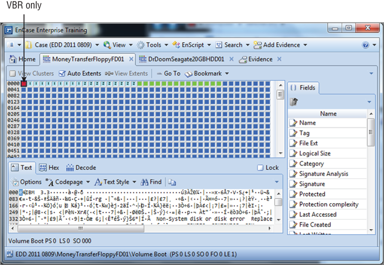
11. The bootstrap code (boot program) has finished one of its two primary missions, that of conducting the POST. Its final task is that of searching the available drives for an operating system according to the order set forth in the boot sequence. Thus, the ROM BIOS boot code looks to the first sector of the default boot hard drive (first on the list in the boot sequence) for the master boot record (MBR) and, finding it, reads it into memory and tests it for a valid signature. The “signature” is hex 55AA (also sometimes rendered 0x55AA, as discussed in Chapter 2), located at the last two bytes of this sector. If this doesn’t match, an error message is returned; otherwise, the boot process continues. Figure 1-1 shows a hard drive with both an MBR and a VBR (volume boot record), and Figure 1-2 shows a floppy disk that has only a VBR.
12. The MBR contains a 64-byte partition table located at byte offsets 446 to 509. Each of up to four partitions is described by 16 bytes in the 64-byte table. The MBR reads its own partition table for the boot indicator byte that marks one of the partitions as the active partition. One partition must be active to boot, and there can’t be more than one partition marked as active. The absence of an active partition or more than one partition marked as active will result in an error message. The MBR reads the VBR of the partition marked as active, loads it into memory, and conducts the same signature test carried out with the MBR, looking for the last two bytes of the VBR to read as hex 55AA. If the signature test fails, an error message is returned. If it passes, the VBR code executes or runs. The VBR code or program searches for and runs the operating system on that volume. What happens next in the boot process depends on the operating system that is loaded on that active bootable partition.
Figure 1-1: Hard disk drive with MBR and VBR
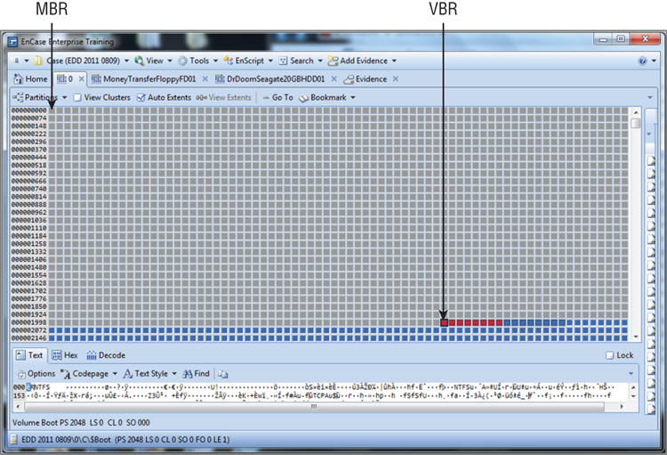
Figure 1-2: Floppy disk drive with VBR only
![]()
The MBR pertains to hard disk drives only. If the bootable media is removable (for example, a floppy disk or USB flash drive), there is no MBR. Rather, only a VBR is located at the first sector. Thus, when the boot is from a floppy, the VBR only is read and executed because there is no MBR on a floppy.
Up through step 12, the boot process is the same whether you’re booting to DOS or to Windows. Steps 13 to 17 will be different for Windows NT/2000/XP, Windows Vista, Windows Server 2003/2008, and Windows 7. I’ll first describe how to boot to DOS, in steps 13 through 17. Next, I’ll explain how to boot to Windows.
DOS boot:
13. The code in the VBR locates and executes the initial or primary system file, which is IO.SYS (IBMBIO.COM for IBM systems). As part of execution, SYSINIT (a subroutine of IO.SYS) runs. This code copies itself into the highest region of contiguous DOS memory. The code next locates and reads MSDOS.SYS, copying it into low memory and overwriting that portion of IO.SYS in low memory that contains the initialization code (SYSINIT), because it is no longer needed there.
14. SYSINIT runs MSDOS.SYS (or IBMDOS.COM for IBM systems). MSDOS.SYS initializes basic device drivers and checks on the status of system equipment. It also resets the disk system, resets and initializes various devices that are attached to the system, and sets default system parameters. It works with the system BIOS to manage files, execute code, and respond to hardware signals.
15. With the DOS file system running and active, SYSINIT (contained within IO.SYS) resumes control of the boot process. SYSINIT reads the CONFIG.SYS file as many times as there are statements within it to process. The DEVICEstatements are processed first, in the order in which they appear, followed by the INSTALL statements in the order of their appearance. Once they are done, if a SHELL statement is present, it is run. If none is present, the default shell with default parameters (COMMAND.COM) is run. SYSINIT is now complete, so COMMAND.COM is written into the section of memory previously occupied by SYSINIT.
16. If the file AUTOEXEC.BAT (.bat is the extension for batch files) is present, COMMAND.COM will run it. Each command in the batch file is executed. If one of the batch commands calls for launching an application or shell, then the user is presented with that interface or prompt. Otherwise, when the batch commands have been executed, the user sees a blinking cursor at a DOS prompt.
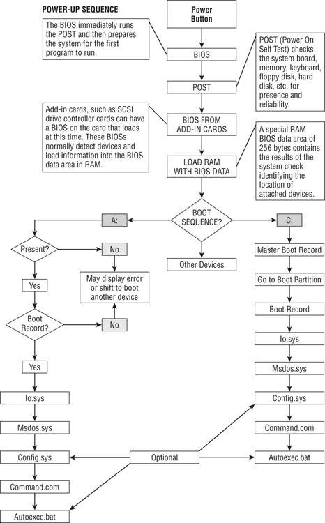
17. If no AUTOEXEC.BAT file is present, COMMAND.COM runs the DATE and TIME commands and displays a copyright message, and then the user is shown a blinking cursor at a DOS prompt. The entire process appears in Figure 1-3.
Figure 1-3: The boot process (DOS)
Windows NT/2000/XP boot:
18. The code in the VBR locates and runs the primary system file, which in the case of the various flavors of Windows NT is NTLDR (often called NT Loader). NTLDR places the processor in the “protected” mode, starts the file system, and reads the contents of the BOOT.INI file. Start-up options and initial boot menu options are determined by the contents of the BOOT.INI file. If dual booting is configured and the other operating system is a non-NT type such as Linux, BOOTSEC.DOS runs. If SCSI drives are attached to the system, another file (NTBOOTDD.SYS) containing the SCSI drivers executes.
19. NTDETECT.COM executes and searches the system for installed hardware and passes configuration data to NTLDR. If more than one hardware profile exists, NTDETECT determines the correct profile for the current hardware and runs that profile.
20. The configuration data obtained in the previous step by NTDETECT is passed by NTLDR to NTOSKRNL.EXE. NTOSKRNL.EXE is the code that loads the kernel, the Hardware Abstraction Layer (HAL), and the system registry information.
21. The next step in the NT boot process is that of loading drivers and code for networking systems, typically TCP/IP. Simultaneously, services that are configured to run at start-up load and run. One of the services is the logon service; it provides the user with a logon prompt, unless configured otherwise. When the user successfully logs on, the current configuration status is considered “good” and is updated into the system registry as Last Known Good Configuration.
22. As logon occurs, device detection takes place as a simultaneous process. If new devices are detected, Plug and Play assigns system resources, extracts drivers from the DRIVER.CAB file, and completes the configuration and mounting of those devices. If drivers can’t be found, the user is prompted to provide them. When done, the user has a graphical user interface (GUI) that allows them to interact with their system and its unique environment of software and hardware.
If the boot is to Windows Vista, Windows Server 2008, or Windows 7, the process, beginning at step 13, differs slightly from that of its Windows predecessors (NT/2000/XP/Server 2003). The boot code in the Windows Vista (and newer) VBR loads a file named BOOTMGR, which is the Windows Boot Manager, instead of NTLDR. Just as NTLDR reads the BOOT.INI file, BOOTMGR reads the BCD file located in the Boot folder, which is located in the root of the system volume. The BCD file is a database of boot-time configuration data.
![]()
BCD (which stands for Boot Configuration Data) is a file located in the Boot directory, which in turn is located in the root of the system volume. This file contains a database of boot-time configuration data, and, interestingly, the file format is the same as that of a registry hive file. This is significant because it means EnCase can mount it when you right-click and then select View File Structure. Just as the BOOT.INI file contained menu entries presented by NTLDR, BCD contains the menu entries presented by the Windows Boot Manager. Those boot options can include, but are not limited to, Windows Vista (and newer) boot options, such as booting a prior version of Windows NT, resuming Windows Vista (and newer) from hibernation, or loading and executing a volume boot record.
In previous Windows versions, NTLDR loaded the kernel (NTOSKRNL.EXE), passing boot configuration information in the process. But Windows Vista’s (and newer) Windows Boot Manager invokes WINLOAD.EXE, which in turn loads the kernel (NTOSKRNL.EXE) and boot-class device drivers. Thus, the process is similar but has differences.
Partitions
Partitions and volumes are terms that are often used interchangeably. Usually this doesn’t cause a problem because typically they are the same thing. There are, however, some subtle differences, and defining the terms and understanding the differences is an important part of being a professional.
A partition is a collection of consecutive sectors within a volume, and those sectors are addressable by a single file system specific to and contained within that partition.
A volume, by subtle contrast, is a collection of addressable sectors that are used by an operating system or an application to store data. The addressable sectors in a volume do not have to be consecutive—and therein lies the difference. Rather, they need only give the appearance of being consecutive. When a volume consists of a single partition, the two are functionally the same. When a volume spans more than one partition or drive, the difference becomes self-evident.
Volumes are logical storage units that are assigned drive letters by the operating systems. Theoretically, most operating systems can support up to 24 volumes, using the letters C through Z and reserving A and B for floppy drives. If a single physical hard drive were installed in a system, that drive could, in theory, be partitioned into 24 volumes. Recall from the earlier discussion, however, that the partition table contained in the master boot record permits only four 16-byte entries for four partitions. How then could such a system support 24 logical volumes?
The answer lies with the extended partition system. One of the four defined partitions in the MBR partition table can be an extended partition. The disk space assigned to the extended partition is further subdivided into logical volumes by the operating system. Each subpartition of the extended volume contains a partition table located in the first sector of that subpartition. That table defines its own subpartition and, optionally, points to another partition table in yet another subpartition. This “nesting” of subpartitions within the extended partition can extend as far as letter assignments permit, and each “nested” subpartition will have a partition table describing itself and pointing to the next level down until done. Seldom will you ever encounter more than few partitions, but in theory, you could encounter the upper limit of 24!
The partition types you can encounter are many and are usually specific to the operating system(s) on the host computer. The fifth byte within each 16-byte partition entry (byte offset 446-509 of the MBR) will determine the partition type/file system for each defined partition. The same holds true for partition tables within the extended partition and their subpartitions. The first byte of each of the four partition table entries determines which partition is active and therefore is the boot partition. Only one partition can be active. Hex 80 denotes the active partition. The other three partition entries, if defined, will have hex 00 for the first byte in their respective entries. Table 1-1 defines the partition table fields.
Table 1-1: Partition Table Fields Defined*
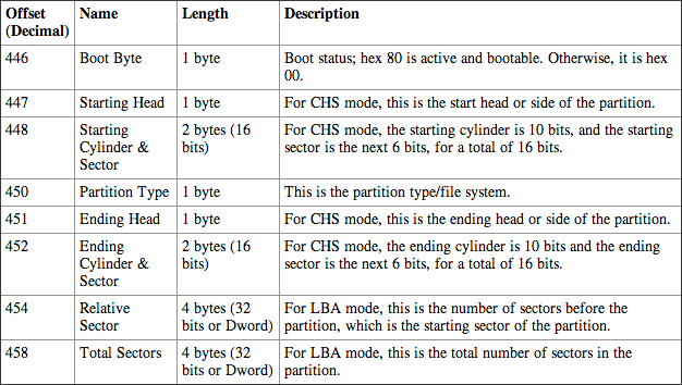
* Fields repeat three more times, if partitions are defined, starting at offsets 462, 478, and 494.
Typically FAT12, FAT16, FAT32, NTFS, and exFAT partitions and file systems are used when running the various flavors of the Windows operating systems. These partitions can be created by utilities that ship with the Windows operating system, such as FDISK, DISKPART, or Disk Manager. Other partition types that are often encountered are Linux Native (EXT2/3/4 and Reiser) and Swap partitions, Solaris (UFS), and Mac OS X (HFS+), all of which are supported in EnCase 6. As with Windows operating systems, partitioning utilities ship with these operating systems. You can also use third-party partitioning utilities to create partitions of varied types, such as Symantec’s PartitionMagic and V-Communications’ Partition Commander.
Using Disk Manager (Windows 2000 and newer), the formatting is done when you use the Create a New Partition Wizard. If a partition is created with FDISK, the partition must be formatted with the high-level format command before it can be used. When you use the format command to format a FAT12/16/32 partition, the following activity occurs:
1. The disk is scanned for errors, and bad sectors are marked.
2. Drive heads are placed at the first cylinder of the partition, and a DOS VBR is written.
3. FAT1 is written to Head 1 Sector 2. Immediately following FAT1, FAT2 is written. The entries in the File Allocation Table (FAT) are mostly null, except that bad clusters are marked.
4. A blank root directory is written.
5. If the /s parameter is selected, the system files are transferred.
6. If the /v parameter is selected, the user is prompted for a volume label.
The following information is written during the FDISK or disk partitioning process:
· The MBR, which contains the MBR booting code
· The partition table entries
· The MBR signature
It is during the high-level formatting process (format) that the VBR is typically written, along with other file system features.
![]()
Somewhat new to the scene is exFAT, which is a proprietary file system developed by Microsoft for flash media. It was actually released in Windows Embedded CE in 2006 but has remained rather obscure until 2010. Gone are the file size limits imposed by FAT, and many examiners will find this file system very useful because it has cross-platform read-write functionality between Windows and OS X, with Linux soon to follow. Windows Vista (SP 1) and newer versions of Windows support exFAT. Legacy versions of Windows (XP and Server 2003) support this format if they have Service Pack 2 or newer and have a special patch update. EnCase recognizes this file system starting with version 6.14.
Exercise 1.1
Examining the Partition Table
In this exercise, you will use EnCase to decode the information contained in the partition table.
1. With EnCase open and a case started, choose Add Evidence > Add Local Device > Next. Select your own boot drive, and select the physical device, not the logical device.
2. From the Evidence > Table tab, double-click your drive to open and parse its file structure.
3. From the resulting Entries View, place your cursor on the root or on Entries in the Entry pane. This will force your devices to appear in the Table pane to the right.
4. Select your device in the Table pane (blue check), go to the Device drop-down list on the toolbar, and choose Disk View. The Disk View will open in its own tab.
5. In the Disk View, go to the first sector, which is sector zero. (This applies to MBR-type partitions only.) Place your cursor on that sector. In the bottom pane, choose the Hex View.
6. Locate and sweep (select by clicking and dragging) bytes 446-509. With these 64 bytes selected, right-click the selected area, and choose Bookmark and then Raw Text.
7. From the Destination Folder tab, choose a new folder and name it Partition Table.
8. On the menu bar, select the drop-down list under View and choose Bookmarks.
9. From the Bookmarks tab, look at the tabs in the bottom section of the Data View pane.
10. First go to the Text tab and see your bookmarked data in this view.
11. Next go to the Hex tab and likewise view your bookmarked data in hex format.
12. Finally, go to the Decode tab; in this view you will see several view types organized in folders.
13. In the Windows folder, choose Partition Entry, and the partition table will be parsed and in the pane to the right, as shown here.
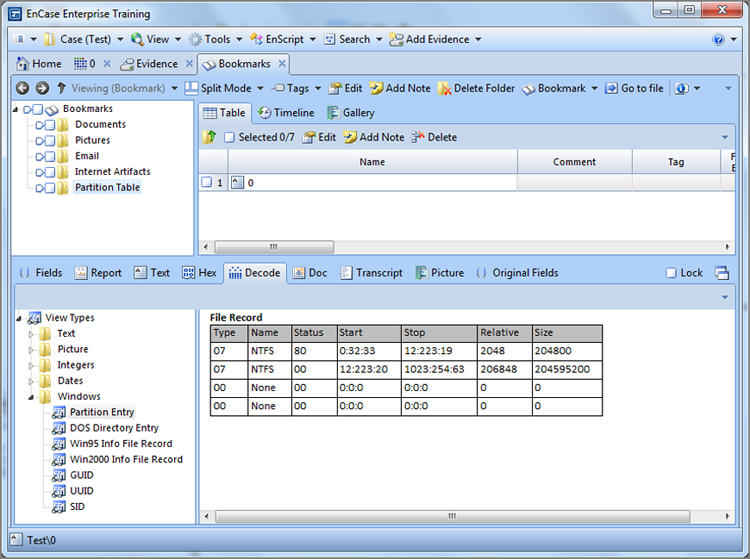
The purposes of this exercise are twofold. The primary and obvious purpose is to use EnCase to examine a partition table. The secondary purpose is to encourage you, the examiner, to use EnCase to examine your own hard drive, which is a good technique for examining known configurations and otherwise conducting research.
![]()
Often FDISK is used to remove the partition, rendering the drive unreadable and causing the user to believe the data is gone. All that really occurs is that the partition table entry is removed. Because each defined and formatted partition contains a VBR, which is untouched by FDISK, the examiner can use EnCase to recover a deleted partition. Simply locate and select the VBR, right-click, and choose Add Partition from the context menu. I cover this technique in detail in Chapter 10.
File Systems
I have, thus far, made reference to file systems in the discussion of partitions and volumes, but I have not yet defined them or described their function and importance in data storage and retrieval. In this section, I’ll discuss file systems in a generic sense. In the chapter that follows, I’ll cover specific file systems in detail.
A file system is nothing more than a system or method of storing and retrieving data on a computer system that allows for a hierarchy of directories, subdirectories, and files. File systems must be consistent between systems using the same file system. If a library used the Dewey Decimal System to store books in one library, a user could go to another library using the same file system and locate a book in that library. Even though the book would be stored in different physical locations in both libraries, a common file system would enable the user to find the book using a common filing and locating system. Computer systems are no different in this regard.
A file system needs its own structural or organization files and data, and the other component is the user data. Because a file system is contained within a partition, there must be data or files that describe the layout and size of the file system, as well as how large the data storage units (clusters, blocks, and so on) will be. The data storage units, which are groups of sectors that hold content data, are referred to as allocation units, clusters, blocks, and similar names depending on the file system being used. A file system needs to have a method or convention for naming data and therefore a system of filenames. Filenames are usually contained in directory entries or as an attribute or field in a database of file and directory names. Filenames have to be linked to actual data comprising that filename so that the operating system can locate the data. Thus, there must be an attribute or metadata (data within data describing data) to point to where the data starts. This is done, usually, via a directory entry (FAT systems) or an entry (field or attribute) in a file table such as the master file table (MFT) in NTFS systems.
Because the data may be larger than one allocation unit can hold, there must be a system that tracks the containing data storage units (clusters, blocks, and so on). In a FAT system, these clusters are linked together in the file allocation table. In NTFS, the clusters containing the data are described by data runs in the MFT. The operating system must know the size of the data so it knows where the data ends in an allocation unit, and that data is typically stored in a directory entry or as an attribute or field in a database of filenames, such as the MFT.
Finally, any file system must have a system that tracks allocation unit usage and availability. Without this function, data could be overwritten. In a FAT system, this is accomplished with the file allocation table. In NTFS and other systems, this is accomplished by the single-purpose volume bit map (VBM), which is an array of bits, with each representing an allocation unit. A 0 means it is available for use, and a 1 means it is allocated.
At a minimum, a file system needs to have the functions described thus far. Most file systems contain much more information about the files they store and have metadata in the form of file attributes about the data. This information may take the form of dates and times for last written, file creation, and last modified. It may also take the form of file permissions or access control lists (ACLs).
In summary, when a partition is created, its boundaries and type are set forth in a partition table. The type is something akin to a zoning ordinance where a given piece of real estate is supposed to be used for a specific purpose. A piece of real estate could be zoned as residential, while a partition type could, similarly, be declared as having a type of Linux Swap. A real estate parcel is described in a deed by its meets and bounds as determined by a survey. A partition’s meets and bounds are described, similarly, in a partition table by its starting point, ending point, and size, based on a survey conducted by the partitioning utility.
When a partition is formatted, among other things, the data structures needed for its specific file system are created. Although these file system type structures are usually consistent with the file system type declared in the partition table, they do not have to be. One could have a FAT32 file system located in a partition type declared as a Linux Swap. This would be somewhat analogous to someone placing a business on real estate zoned for residential use. If you were using Linux for the operating system, Linux does not rely on the partition type; if instructed to mount the partition as FAT32, it would do so since the structure for FAT32 is present regardless of the declared type. Linux ignores the “zoning laws.” Windows, however, strictly obeys zoning laws and would not permit an office in a residential zone. Windows relies on declared partition types for mounting partitions and file systems and would not mount a FAT32 partition declared as a Linux Swap partition or any other type not a FAT32. In this manner, partitions and file systems can be hidden from Windows.
File systems are the management tools for storing and retrieving data in a partition. Some operating systems require certain file systems for them to function. Windows needs a FAT or NTFS file system, depending on its version and won’t recognize or mount other systems with its own native operating system. Third-party software can enable mounting and reading (sometimes writing) other file systems from within the Windows environment. EnCase and VMware are two examples. Many different file system schemes have been developed, and more will be forthcoming as computing evolves. In the next chapter, I’ll cover FAT in detail.
Summary
This chapter explained the computer’s components, as well as its boot process, partitions, and file systems. I covered computer hardware components, including their acronyms, attributes, functions, and purpose. In addition, I covered the two major components of the boot process. The first is the Power On Self-Test, in which the major components are tested and initialized (added to the system). The second consists of the bootstrap code locating a bootable drive and loading the specified operating system.
I also defined and described partitions and volumes. A partition is a collection of consecutive sectors within a volume and is a container for a file system, with specific boundaries and properties. A volume is a collection of addressable sectors that are used by an operating system or an application to store data. A volume is assigned a drive letter by the operating system; it may be limited to a single partition, or it may span partitions or physical hard drives. Finally, I discussed file systems and their purpose, function, and necessary generic components.
Exam Essentials
Know computer hardware components. Understand the proper terminology, acronyms, purpose, and function of the various computer hardware components.
Be familiar with the boot process. Understand and be able to describe the POST process. Understand and be able to describe the process by which the system boots and loads an operating system.
Understand partitions and volumes. Understand and be able to describe partitions and volumes, what the differences are, and how they are created. Understand the MBR and VBR, where they are found, their contents (boot code, partition table, signature), and how and when they are created. Understand a partition table, where it is located, its structure, length, and general properties.
Understand file systems in general. Understand the purpose of a file system as a means to store and retrieve data. Be familiar with the functional components of any generic file system so as to be able to apply them to specific file systems.
Review Questions
1. What is the definition of a CPU?
A. The physical computer case that contains all its internal components
B. The computer’s internal hard drive
C. A part of the computer whose function is to perform data processing
D. A part of the computer that stores and manages memory
2. What is the BIOS?
A. BIOS stands for Basic Input Output System and is a combination of low-level software and drivers that function as the interface, intermediary, or layer between a computer’s hardware and its operating system.
B. BIOS stands for Bootstrap Initialization Operating System and is a combination of low-level software and drivers that function as the interface, intermediary, or layer between a computer’s hardware and its operating system.
C. BIOS stands for Boot-level Input Output System and is a combination of low-level software and drivers that function as the interface, intermediary, or layer between a computer’s hardware and its operating system.
D. BIOS stands for Boot Initialization Operating System and is a combination of low-level software and drivers that function as the interface, intermediary, or layer between a computer’s hardware and its operating system.
3. What is the definition of POST?
A. A set of computer sequences the operating system executes upon a proper shutdown
B. A diagnostic test of the computer’s hardware and software for presence and operability during the boot sequence prior to running the operating system
C. A diagnostic test of the computer’s software for presence and operability during the boot sequence prior to running the operating system
D. A diagnostic test of the computer’s hardware for presence and operability during the boot sequence prior to running the operating system
4. Is the information stored on a computer’s ROM chip lost during a proper shutdown?
A. Yes
B. No
5. Is the information contained on a computer’s RAM chip accessible after a proper shutdown?
A. Yes
B. No
6. Can information stored in the BIOS ever change?
A. Yes
B. No
7. What is the purpose or function of a computer’s ROM chip?
A. Long-term or permanent storage of information and instructions
B. Temporary storage area to run applications
C. Permanent storage area for programs and files
D. A portable storage device
8. Information contained in RAM memory (system’s main memory), which is located on the motherboard, is _________ .
A. volatile
B. nonvolatile
9. What is the maximum number of drive letters assigned to hard drive(s) partitions on a system?
A. 4
B. 16
C. 24
D. Infinity
10. The smallest area on a drive that data can be written to is a _______, while the smallest area on a drive that a file can be written to is a ________.
A. bit and byte
B. sector and cluster
C. volume and drive
D. memory and disk
11. The size of a physical hard drive can be determined by which of the following?
A. The cylinder × head × sector
B. The cylinder × head × sector × 512 bytes
C. The total LBA sectors × 512 bytes
D. Adding the total size of partitions
E. Both B and C
12. Which is not considered exclusively an output device?
A. Monitor
B. Printer
C. CD-RW drive
D. Speaker
13. The electrical pathway used to transport data from one computer component to another is called what?
A. Bus
B. RAM
C. CMOS
D. BIOS
14. What is the main component of a computer to which essential internal devices such as CPU, memory chips, and other chipsets are attached?
A. BIOS
B. Motherboard
C. Expansion card
D. Processor
15. IDE, SCSI, and SATA are different types of interfaces describing what device?
A. RAM chips
B. Flash memory
C. CPUs
D. Hard drives
16. What do the terms master, slave, and Cable Select refer to?
A. External SCSI devices
B. Cable types for external hardware
C. Jumper settings for internal hardware such as IDE hard drives and CD drives
D. Jumper settings for internal expansion cards
17. What can you assume about a hard drive that is pinned as CS?
A. It’s an IDE drive.
B. It’s a SATA drive.
C. It’s a SCSI drive.
D. All of the above.
18. What is found at Cylinder 0, Head 0, Sector 1 on a hard drive?
A. Master boot record
B. Master file table
C. Volume boot record
D. Volume boot sector
19. What is the first sector on a volume called?
A. File allocation table
B. Volume boot record or sector
C. Master boot record
D. Volume boot device
20. Which of the following is incorrect?
A. The MBR is typically written when the drive is partitioned with FDISK or DISKPART.
B. A file system is a system or method of storing and retrieving data on a computer system that allows for a hierarchy of directories, subdirectories, and files.
C. The VBR is typically written when the drive is high-level formatted with a utility such as format.
D. The partition table is contained within the MBR and consists of a total of 16 bytes, which describes up to four partitions using 4 bytes each to do so.
All materials on the site are licensed Creative Commons Attribution-Sharealike 3.0 Unported CC BY-SA 3.0 & GNU Free Documentation License (GFDL)
If you are the copyright holder of any material contained on our site and intend to remove it, please contact our site administrator for approval.
© 2016-2026 All site design rights belong to S.Y.A.