EnCase Computer Forensics (2012)
Chapter 2
File Systems
EnCE Exam Topics Covered in This Chapter:
· FAT12 file system
· FAT16 file system
· FAT32 file system
· Other file systems (NTFS, CD, and exFAT file systems)
In the previous chapter, we made many references to file systems and discussed generally what a file system is and its functional purpose. We referenced some file system names, such as FAT, NTFS, and Linux’s EXT2/3/4. In this chapter, we thoroughly cover the File Allocation Table (FAT) file system’s internal structures and function, and we touch on the New Technology File System (NTFS) and CD file systems.
The FAT file system has been around for nearly a quarter of a century and will be with us for the foreseeable future. It is still used with floppy drives, Flash media, and USB thumb drives, and it can still be used, optionally, with Windows XP and Windows Vista. In fact, Flash media in all of its various flavors (thumb drives, memory sticks and cards, and so forth) has given a resurgence to FAT file systems, because they nearly all come formatted in FAT. It is truly the one cross-platform file system that is both readable and writable by all major operating systems. Windows 2000, Windows XP, Windows Server 2003, Windows Vista, Windows Server 2008, and Windows 7 default to NTFS, but if upgrading to a newer operating system, they default to the former file system. If that former file system happened to be FAT, FAT will be the default. Thus, as a computer forensics examiner, you will encounter many cases involving FAT from both legacy and new systems for years to come.
In this chapter, you will learn about the data structures of the FAT file system, which consists of two major components: the File Allocation Table and the directory entries. You will learn how the directory entries store filenames and attributes (metadata), how the FAT is used both to track the allocation status of the data storage area (organized as clusters) and to link together the clusters used to store data. You will understand how the FAT system has been tweaked over the years to handle increasingly larger data storage devices. Finally, you will be exposed briefly to various CD file systems, the components of the NTFS file system, and features of the newest file system from Microsoft, exFAT. I’ll also explain the similarities and differences among all these systems.
FAT Basics
The first major component of the FAT file system is the directory entry. In all versions of the FAT file system (FAT12, FAT16, and FAT32), every file and directory is referenced and described in a separate directory entry. The directory entry is 32 bytes in length and contains the file’s or directory’s name, its size in bytes, its starting extent (or beginning cluster), and other file attributes or metadata (created, last-accessed, and last-written time stamps, and so on). None of the data content exists in the directory entry; rather, data content is stored in data allocation units called clusters. Clusters consist of one or more sectors, and a cluster is the smallest unit in which a file or directory can be stored. If a file’s size exceeds the amount that can be contained in one cluster, it is assigned as many additional clusters as are needed to contain its data. The directory entry tracks only the starting cluster and does not track the other clusters used by a file.
The other major component of the FAT file system is the File Allocation Table, or FAT, which, among other functions, tracks the sequence of clusters used by a file when more than one cluster is allocated or used. In addition to tracking cluster runs or sequences, the FAT also tracks the allocation status of clusters, assuring that the operating system stores data in clusters that are available, and that clusters storing data assigned to files or directories aren’t overwritten. The FAT also tracks bad clusters, marking them as such so they won’t be used.
The FAT file system comes in three versions that have evolved over time to accommodate the continual development of larger-capacity hard drives. The three versions of FAT are FAT12, FAT16, and FAT32. The number following FAT describes the size of the entries in the FAT.
In a FAT12 system, the table is an array of 12-bit entries, with each 12-bit sequence representing a cluster, starting at cluster 0 and ending with the last cluster in the volume. The theoretical maximum number of clusters for a 12-bit array is 4,096 (212), but certain values are reserved, making 4,084 clusters the largest number of clusters supported by a FAT12 system.
Similarly, a FAT16 system has 16-bit FAT entries, and a FAT32 has 32-bit entries (although only 28 are used). Taking into account certain reserved values, a FAT16 system supports up to 65,524 clusters, and a FAT32 supports up to a theoretical maximum of 268,435,445 clusters (but the master boot record [MBR] imposes a limit of 67,092,481 clusters, which makes FAT32 capable of supporting a partition size of 2 terabytes). There are some other differences between FAT12/16 and FAT32, but the major difference lies in the number of clusters they can support, as shown in Table 2-1.
Table 2-1: Maximum number of sectors supported by FAT types
|
FAT type |
Maximum number of clusters supported |
|
FAT12 |
4,084 |
|
FAT16 |
65,524 |
|
FAT32 |
67,092,481 |
The Physical Layout of FAT
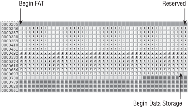
The FAT file system, as shown in Figure 2-1, has a distinctive physical layout consisting of three major components:
· Reserved area (volume boot sector)
· FAT (File Allocation Table) area
· Data storage area (directory entries and data content)
Figure 2-1: Physical layout of FAT showing the three major components
Reserved Area
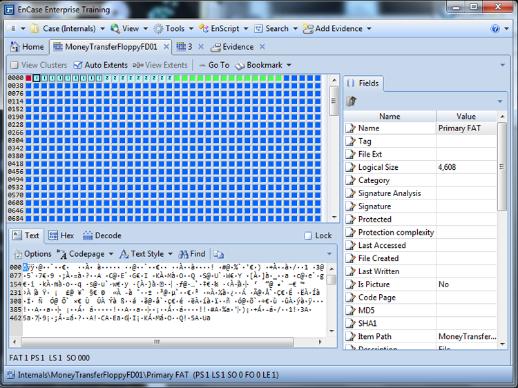
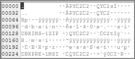
The reserved area consists of the volume boot sector, often abbreviated as simply boot sector. The size of this reserved area is defined within the boot-sector data, but most often FAT12 and FAT16 systems use only one sector for this data. (See Figure 2-2.)
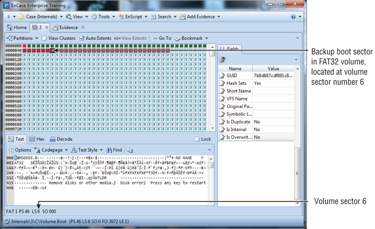
With FAT32 systems, the size of this area is likewise defined in the boot sector, but because it contains significantly more data, it will be several sectors in length (sectors 0, 1, and 2, with backups at sectors 6, 7, and 8), and the reserved area will usually be 32 sectors in length. (See Figure 2-3.) The backup copy of the boot sector (see Figure 2-4) is unique to FAT32 and runs if volume sector 0, the boot sector, is corrupted. Although its location is specified in the boot sector (as a sector number at byte offsets 50-51 in the boot sector), Microsoft standards call for it being located at volume sector 6. It makes sense to have the backup boot sector located in a standard location. If its location were variable and that variable location relied on data in sector 0, a corrupted sector 0 could destroy the system’s ability to find its backup boot sector.
Figure 2-2: Reserved area (boot sector) of the FAT12 file system using only one sector
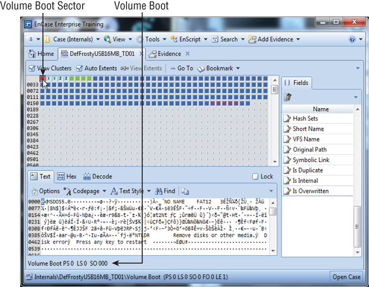
Figure 2-3: Reserved area of a FAT32 file system using 32 sectors
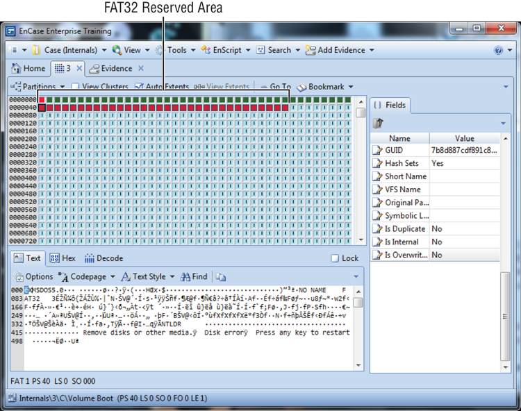
Figure 2-4: Backup boot sector unique to the FAT32 file system
Also unique to FAT32 is a data structure known as File System Information, or the FSINFO. Its location is specified as a sector number at byte offsets 48-49 in the boot sector, but it is typically found in sector 1, immediately following the boot sector and sandwiched between the boot sector (sector 0) and sector 2, which is a continuation of the FAT32 bootstrap code. Additionally, a backup copy of the FSINFO is maintained in the sector immediately following the backup boot sector, which is sector 7 (the backup boot sector is, by standard, located in sector 6). Its purpose is to provide information to the operating system about the number of free clusters available to the system and the location of the next free cluster. Interestingly, this data is only “suggested” information for the operating system and may or may not be used. Also, this data may or may not be updated or accurate; often the backup copy does not match the primary. Nevertheless, it is a feature unique to FAT32.
The volume boot sector, also called the volume boot record (VBR), is located at the first sector of the logical volume. It is the first sector of the reserved area; in FAT12/16, it is often the only sector in the reserved area. The boot sector contains four distinct segments:
· Jump instruction to the boot code (first 3 bytes).
· BIOS parameter block, or BPB (bytes 3-61 for FAT12/16 and bytes 3-89 for FAT32).
· Boot code and error messages (bytes 62-509 for FAT12/16 and bytes 90-509 for FAT32). Note: FAT32 boot code continues at sector 2, bytes 0-509.
· Signature (bytes 510-511; should be 0x55AA).
The jump instruction tells the machine where to find the beginning of the OS bootstrap code located in that sector. Bytes 3-35, as well as bytes 0-2, have the same structure and purpose for all three versions of FAT. Bytes 36-61 have a structure and purpose unique to FAT12/16, while bytes 36-89 have a structure and purpose unique to FAT32. The area beyond byte 61 for FAT12/16 and beyond byte 89 for FAT32, except for bytes 510-511 (the boot sector signature), is used for the bootstrap code, referenced in the first 3 bytes, as well as for error messages.
The BPB is nothing more than a database of sorts, with defined fields that set forth the parameters of the partition and the file system within. The boot sector can be demystified by breaking down the data into its components, as shown in Table 2-2 and Table 2-3.
Table 2-2: Volume boot sector format—FAT12/16 file system
|
Byte offset (decimal) |
Name or description and purpose |
|
0-2 |
Assembly jump instruction to bootstrap code found in this sector, usually 0xEB3C90. |
|
3-10 |
OEM ID in ASCII; indicates the OS that formatted the volume:Win95 = MSWIN4.0Win2K/XP/Vista = MSDOS5.0Linux = mkdosfs(When Linux mkfs msdos command is used to create.) |
|
11-12 |
Bytes per sector; usually 512, but 1,024, 2,048, or 4,096 may occur. |
|
13 |
Sectors per cluster; value must be a power of 2 and greater than 0. Typical values are 1, 2, 4, 8, 16, 32, or 64. |
|
14-15 |
Number of sectors in the reserved area. FAT12/16 is typically one. |
|
16 |
Number of FATs; typically, this is 2, with FAT1 and FAT2 (FAT2 is a duplicate of FAT1 for redundancy). According to Microsoft, some small devices can have only one FAT! |
|
17-18 |
Maximum number of 32-byte directory entries in the root directory. This is typically 512 for FAT12/16 and 0 for FAT32. |
|
19-20 |
16-bit integer describing the number of sectors in the partition. If 0, the number exceeds 65,536 and the byte offset 32-35 is a 32-bit integer describing the number of sectors in the partition. |
|
21 |
Media descriptor; according to Microsoft, 0xF8 should be used on nonremovable media (hard disks), and 0xF0 should be used for removable media. This entry is duplicated in the first entry of the FAT where cluster 0 would be described, but since there is no addressable cluster 0 or 1, this value is used instead. |
|
22-23 |
16-bit integer that describes number of sectors used by each FAT in FAT12/16. For FAT32, expect a value here of 0. |
|
24-25 |
Sectors per track value for interrupt 13h, typically 63 for hard disks. |
|
26-27 |
Number of heads value for interrupt 13h, typically 255 for hard disks. |
|
28-31 |
Number of hidden sectors before the start of the partition, typically 63 for the first volume on a hard disk. |
|
32-35 |
32-bit integer describing the number of sectors in the partition. If 0, the number does not exceed 65,536 and is described as a 16-integer in bytes 19-20. Only one of the two (19-20 or 32-35) and not both must be set to 0. |
|
36 |
Interrupt 13h drive number, which is 0x00 for floppies or 0x80 for hard drives. |
|
37 |
Not used except by Windows NT; should typically be 0. |
|
38 |
Extended boot signature to determine the validity of the three fields that follow. If 0x29, the next three fields are present and valid. If otherwise, expect 0x00. |
|
39-42 |
Volume serial number; used with the field that follows to track volumes on removable media. With some OSs this value is generated using a date/time seed value at time of creation. |
|
43-53 |
Volume label in ASCII; the volume label is optionally given by the user at the time of creation. Its limit is 11 bytes, and it should match the value in the root directory of FAT12/16. If none is given by the user, “NO NAME” should appear here. |
|
54-61 |
File system type at time of formatting. Shown in ASCII as FAT, FAT12, or FAT16. It is not used after formatting and could be altered. |
|
62-509 |
Bootstrap program code and error messages. |
|
510-511 |
Signature value; 2 bytes and should be 0x55AA. |
Table 2-3: Volume boot sector format—FAT32 file system
|
Byte offset (decimal) |
Name or description and purpose |
|
0-2 |
Assembly jump instruction to bootstrap code found in this sector, usually 0xEB3C90. |
|
3-10 |
OEM ID in ASCII; indicates the OS that formatted the volume:Win95 = MSWIN4.0Win98 = MSWIN4.1Win2K/XP/Vista = MSDOS5.0Linux = mkdosfs |
|
11-12 |
Bytes per sector; usually 512, but 1,024 or 2,048 or 4,096 may occur. |
|
13 |
Sectors per cluster; value must be a power of 2 and greater than 0. Typical values are 1, 2, 4, 8, 16, 32, or 64. |
|
14-15 |
Number of sectors in the reserved area. FAT12/16 is typically one. |
|
16 |
Number of FATs; typically, this is 2, with FAT1 and FAT2 (FAT2 is a duplicate of FAT1 for redundancy). According to Microsoft, some small devices can have only one FAT! |
|
17-18 |
Maximum number of 32-byte directory entries in the root directory. This is typically 512 for FAT12/16 and 0 for FAT32. |
|
19-20 |
16-bit integer describing the number of sectors in the partition. If 0, the number exceeds 65,536, and the byte offset 32-35 is a 32-bit integer describing the number of sectors in the partition. |
|
21 |
Media descriptor; according to Microsoft, 0xF8 should be used on nonremovable media (hard disks), and 0xF0 should be used for removable media. This entry is duplicated in the first entry of the FAT where cluster 0 would be described, but since there is no addressable cluster 0 or 1, this value is used instead. |
|
22-23 |
16-bit integer that describes the number of sectors used by each FAT in FAT12/16. For FAT32, expect a value here of 0. |
|
24-25 |
Sectors per track value for interrupt 13h, typically 63 for hard disks. |
|
26-27 |
Number of heads value for interrupt 13h, typically 255 for hard disks. |
|
28-31 |
Number of hidden sectors before the start of the partition, typically 63 for the first volume on a hard disk. |
|
32-35 |
32-bit integer describing the number of sectors in the partition. If 0, the number does not exceed 65,536 and is described as a 16-integer in bytes 19-20. Only one of the two (19-20 or 32-35) and not both must be set to 0. When FAT32, this number cannot be 0. |
|
36-39 |
32-bit integer describing the number of sectors used by one FAT on FAT32 partition; bytes 22-23 must be set to 0 for FAT32. |
|
40-41 |
A series of bit-field values used in FAT32 to describe how multiple FATs are written to. If bit 7 is off (value 0), then FAT is duplicated. If it is on (value 1), then duplication is disabled and only the FAT referenced in bits 0-3 is active. Bits 0-3 are valid only if bit 7 is “on” and duplication is not occurring. Bits 4-6 and 8-15 are reserved. The default is 0x0000, meaning that FAT1 and FAT2 are replicated. |
|
42-43 |
The major and minor version numbers of the FAT32 volume, with the high byte being the major and the low byte being the minor. Expect values of 0x00 and 0x00. |
|
44-47 |
Cluster number where the root directory begins, usually cluster 2. Remember that cluster 2 is the first addressable cluster, and on a FAT32 starts immediately after FAT2 ends. Entries in FAT for clusters 0 and 1 are used for purposes other than addressing clusters. |
|
48-49 |
Sector number for where FSINFO can be found, usually 1; a backup FSINFO follows sector 6 (location of backup boot sector) and is found at sector 7. |
|
50-51 |
Sector number for location of backup boot sector, which defaults to sector 6. |
|
52-63 |
Reserved and not currently used. |
|
64 |
Interrupt 13h drive number, which is 0x00 for floppies or 0x80 for hard drives. |
|
65 |
Not used except by Windows NT; should typically be 0. |
|
66 |
Extended boot signature to determine the validity of the three fields that follow. If 0x29, the next three fields are present and valid. If otherwise, expect 0x00. |
|
67-70 |
Volume serial number; used with the field that follows to track volumes on removable media. With some OSs this value is generated using a date/time seed value at time of creation. |
|
71-81 |
Volume label in ASCII; volume label is optionally given by the user at the time of creation. Its limit is 11 bytes, and it should match the value in the root. If none is given by the user, “NO NAME” should appear here. |
|
82-89 |
File system type at time of formatting. Shown in ASCII as FAT32. Not used after formatting and could be altered. |
|
90-509 |
Bootstrap program code and error messages. Note: FAT32 boot program code continues at sector 2, bytes 0-509. |
|
510-511 |
Signature value; 2 bytes and should be 0x55AA. |
FAT Area
The second major physical feature of the FAT file system is the File Allocation Table itself, which begins with the sector that follows the last sector of the reserved area. By default, there are usually two FATs (FAT1 and FAT2) in a FAT file system, as shown in Figure 2-5. The exact number of FATs, the size of a FAT, and the total size for all FATs are specified in the boot sector as described earlier.
Figure 2-5: Default FAT configuration showing FAT1 (selected) immediately followed by FAT2
The FAT, as previously mentioned, has two purposes:
· To account for the allocation status of a cluster
· To find the clusters that follow the starting cluster (if any) for any given file or directory
FAT1 starts immediately following the reserved sectors. FAT2, a duplicate of FAT1, is a default configuration and immediately follows FAT1. A second FAT (FAT2) is, however, not required, and a system could be configured to have only one FAT. FAT1 and FAT2 are equal in size and normally a duplicate image of each other.
Each cluster on the file system will be represented sequentially starting with cluster 0 in the table, with each entry or array of bits depending on which version of FAT is used. For FAT12, each entry is 12 bits; for FAT16, each entry is 16 bits; and for FAT32, each entry is 32 bits, with 28 used and 4 in reserve. Remember that cluster 2 is the first addressable cluster in all versions of FAT. With FAT12/16, cluster 2 starts immediately following the fixed-length root directory. With FAT32, cluster 2 starts immediately following the end-of-file allocation tables.
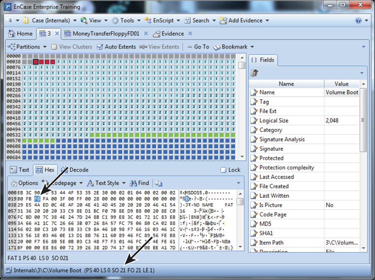
The first 16-bit FAT entry in a FAT16 file system is for nonaddressable cluster 0, which is used to store the value for the media type. As you can see in Figure 2-6, this value is 0xFFF8, or 0xF8 because the leading 0xFF is ignored in this case. This value (0xF8) should match the value at byte 21 in the boot sector (0xF8 should be used on nonremovable media, and 0xF0 should be used for removable media). As you can see in Figure 2-7, this value is 0xF8.
Figure 2-6: FAT entry for nonaddressable cluster 0, which contains the value for the volume media type, in this case 0xF8
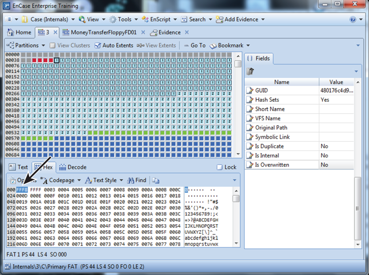
Figure 2-7: Byte offset 21 in the boot sector should and does match value in cluster entry 0 (Figure 2-6), which in this case is 0xF8.
The FAT entry for nonaddressable cluster 1, shown in Figure 2-8, is used to store the value for the “dirty status” of the file system. If a file system was not properly “dismounted,” usually from an improper system shutdown, this value is used to track that status, causing the OS to prompt the user to check the file system during a reboot. This value may or may not be accurate in this regard.
The third 16-bit entry in the FAT16 table represents cluster 2, which is the first addressable cluster in the FAT file system. For this entry and all others that follow in FAT1, certain values will be present:
· Unallocated; represented by the value of 0, meaning that the cluster is available for use by the operating system to store a file or directory.
· Allocated; its value will be represented by the next cluster used by the file, unless it is the last cluster used by the file (see item 3).
· Allocated; the last cluster used by the file. This will be populated by the end-of-file marker, which is a value greater than 0xFF8 for FAT12, greater than 0xFFF8 for FAT16, and greater than 0xFFFF FFF8 for FAT32.
· Bad cluster; not available for use by the operating system. This value will be 0xFF7 for FAT12, 0xFFF7 for FAT16, and 0xFFFF FFF7 for FAT32.
Figure 2-8: FAT entry for nonaddressable cluster 1, which contains the value for the “dirty status” of the file system

Data Storage Area
The third major physical component of the FAT file system is the data area. The data area contains the clusters used to store directory entries and their data.
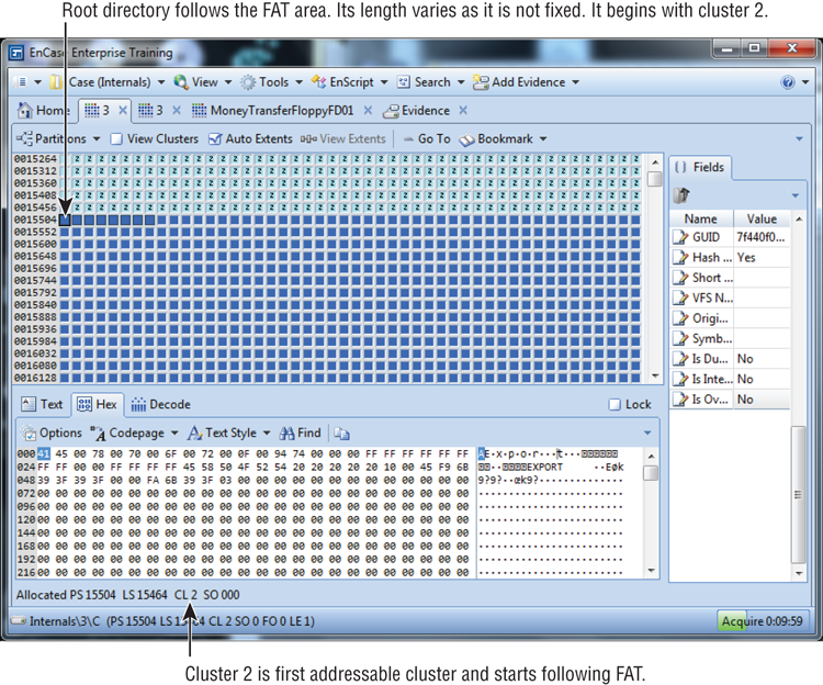
Location of Root Directory
With FAT12/16, the root directory is the first part of the data area, which immediately follows at the end of the FAT area. The root directory is a fixed-length feature with FAT12/16 systems; a maximum of 32 sectors are allowed for it. Each directory entry is 32 bytes in length. I cover its structure in depth later in this chapter. Because a root directory in FAT12/16 systems has a maximum of 32 sectors, the number of bytes available to the root directory is 16,384 bytes (32 sectors × 512 bytes per sector). Since each directory entry is a fixed-length entry consisting of 32 bytes, the maximum number of directory entries in a FAT12/16 system is 512 entries (16,384 bytes divided by 32 bytes per entry). Cluster 2 immediately follows the root directory in a FAT12/16 system, followed by all the clusters contained within the defined partition.
As the size of software and hard disk capacity grew in the mid-1990s, the limitations of FAT12/16 file systems necessitated the development of the FAT32 file system. From our previous discussions, you already know that FAT32 allows for a greater number of clusters than its FAT12/16 predecessors. FAT32 also overcame the limitation of 512 entries in the root directory by making the directory “dynamic”—in that its size is not fixed and it can appear anywhere in the data area. When you examine the data area of a FAT32 system, you will see a difference at the very beginning. With FAT12/16, cluster 2 started after the fixed-length root directory, as shown in Figure 2-9. With FAT32, cluster 2 starts immediately following the end of the FAT area, as shown in Figure 2-10. Interestingly, even though the root directory can occur anywhere in the data area of a FAT32 file system, it almost always begins with cluster 2.
Figure 2-9: FAT12/16 physical layout, showing the fixed-length root directory immediately following the FAT
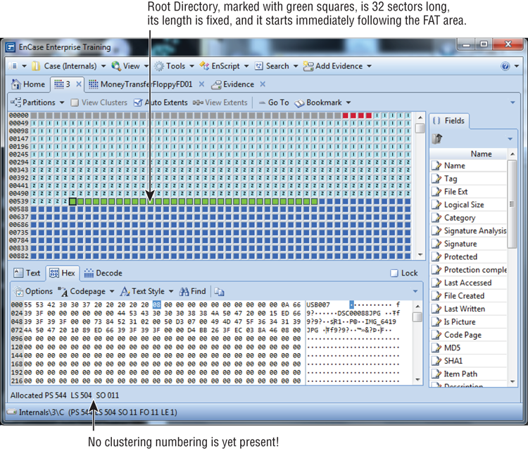
Figure 2-10: FAT32 physical layout, showing cluster 2 starting immediately after the FAT
As previously mentioned, the data area contains the clusters that include the directory entries and the contents of the files and directories. FAT12/16 file systems keep the root directory outside, and prior to the cluster structure, which fixes its size and imposes a limitation on the number of directory entries, it can hold up to 512 entries. FAT32 places the root directory inside the cluster area and thereby imposes no limit on its size.
Directory Entries
Thus far, I’ve mentioned directory entries, but I haven’t yet fully described their function, let alone their internal structures. The directory entry is a critical component of the FAT file system. For every file and directory within a partition, a directory entry exists. Regardless of which version of FAT is used, each directory entry is 32 bytes long. Within these 32 bytes, the name of the file or directory, its starting cluster, and its length are described, along with other metadata or attributes. These directory entries are found in the cluster(s) allocated to the file’s parent directory.
In this and many systems, the parent directory keeps track of its children, be they files or subdirectories. If parent directory structures are deleted, children can become orphaned, and thus you have lost files or folders, which are files and folders for which no parent directory structure can be found.
A 32-byte directory has sufficient space to name a file or folder (directory) using an “8 dot 3” DOS naming convention, with a maximum of eight characters for the filename and three characters for its extension. No “dot” (a period) actually exists in the directory entry. Should a long filename exist, an attribute set in the metadata is created, and a series of 32-byte entries, sufficient to contain the long filename, will precede its main 32-byte entry. Table 2-4displays the data structure for the FAT directory structure. Table 2-5 shows the bit-flag values for the various file or directory attributes.
Table 2-4: Data structure for FAT directory entry
|
Byte offset (decimal) |
Description |
|
0 |
First character of the filename or status byte. |
|
1-7 |
Characters 2-8 of the filename. |
|
8-10 |
Three characters of the file extension. |
|
11 |
Attributes (detailed in Table 2-5). |
|
12-13 |
Reserved. |
|
14-17 |
Created time and date of file; stored as MS-DOS 32-bit date/time stamp. |
|
18-19 |
Last accessed date; no time is stored in FAT! |
|
20-21 |
Two high bytes of FAT32 starting cluster; FAT12/16 will have zeros. |
|
22-25 |
Last written time and date of file; stored as MS-DOS 32-bit date/time stamp. |
|
26-27 |
Starting cluster for FAT12/16; two low bytes of the starting cluster for FAT32. |
|
28-31 |
Size in bytes of file (32-bit integer). Note: will be 0 for directories! |

Determining the starting cluster for a FAT12/16 partition is a snap. You merely decode the 2 bytes at byte offsets 26-27 as a 16-bit little endian integer, and you have the value. When the partition is FAT32, things get interesting. The data you need to make this determination is in two different locations and must be combined in the correct order to arrive at the correct value. To illustrate how this is done, consider the following hex values as constituting a FAT32 directory entry: 48 49 42 45 52 46 49 4C 53 59 53 26 18 02 C2 4C 25 30 26 30 12 00 6A 4A 26 30 03 00 00 80 F8 0F. The bold values constitute the high bytes and low bytes, respectively, of this 32-bit value. To properly combine and calculate this value, you must enter the hex values into a scientific calculator in the following order: 00 12 00 03. This converts the stored values to little endian. The resulting decimal value for this starting cluster would be 1,179,651.
![]()
In the previous note, I mentioned the term little endian. For those of you not familiar with the term, it is, in essence, reverse-byte ordering. This is a method of storing a number so that its least significant byte appears first in the first hexadecimal number in the case of a 2-byte value. Thus, in the case of a hexadecimal value of FDBA, the little endian method would cause the number to be stored as BAFD, while the big endian method would cause the number to be stored as it is, or FDBA. Intel microprocessors use the little endian method, and Motorola microprocessors use the big endian method. If you’d like to understand more about hexadecimal and integers, jump ahead to Chapter 7, “Understanding, Searching For, and Bookmarking Data.”
Table 2-5: Bit flag values for attribute Field at byte offset 11
|
Bit flag values (binary) |
Description |
|
0000 0001 |
Read only |
|
0000 0010 |
Hidden file |
|
0000 0100 |
System file |
|
0000 1000 |
Volume label |
|
0000 1111 |
Long file name |
|
0001 0000 |
Directory |
|
0010 0000 |
Archive |
Attributes’ bit flag values can be combined, and the resultant hex value will reflect those combinations. If a file were a read-only hidden system file, it would have the following bit flags turned on: 0000 0111. The hex value representing such a combination would be 0x07.
When long filenames are used—ones that exceed the length of the DOS 8 dot 3 limit or contain “illegal” DOS 8 dot 3 characters—special entries are created in the directory entry to accommodate filenames up to 255 characters in length (including the length of the path). When a long filename is created, an “8 dot 3 alias” is created as the filename in the 32-byte entry. It is done according to the following scheme (Windows 9x/ME):
· The first three characters of the extension (following the dot) are used as the extension of the 8 dot 3 alias.
· The first six characters of the filename (spaces ignored) are rendered to uppercase and become the first six characters of the 8 dot 3 alias file name. Any “illegal” DOS 8 dot 3 characters are converted to underscores.
· Two characters are added to the six characters. Character 7 is a tilde (~). Character 8 is the numeral 1. If another file exists that has the same alias name, the 1 sequences to 2, and so forth, until a number is assigned for which there is no duplicate alias file name.
If you were to create a file named SQL + Oracle Hacks.hash, the resultant 8 dot 3 alias filename would be SQL_OR~1.HAS. The spaces are ignored, and the plus (+), which is illegal, becomes an underscore (_). All characters become uppercase. After the r in Oracle, the six-character limit has been reached, and the characters ~1 are appended. The alias extension, HAS, is the first three characters of the long file name (LFN) extension.
![]()
Windows NT/2000/XP/Vista/7 handles alias creation with a slightly different scheme. The first six legal DOS characters in a long file name are used as the alias; they are appended with ~1 if the first six characters are unique. If not, ~2, and so forth, is used. For the extension, the first three legal characters of the LFN extension are used for the alias extension. As if that weren’t enough, yet another scheme is applied by Windows NT/2000/XP/Vista/Win7 whereby the first two characters of the LFN are taken for the first two characters of the alias. The LFN is hashed, and the next four characters are the hexadecimal values of that hash. Characters 7 and 8 are ~5. The ~5 remains constant for all subsequent aliases, with only the hash values, and hence the hex values, changing.
The long filename itself is stored in a series of 32-byte entries that immediately precede the directory entry containing the 8 dot 3 alias. The long filename is stored in accordance with the convention described in Table 2-6.
Table 2-6: Long file name storage scheme
|
Byte offset |
Description |
|
0 |
Sequence number used to link together multiple LFN entries. 0xE5 if deleted or unallocated. Typically the first LNF entry above the alias 8 dot 3 entry contains the beginning of the LFN, and they build on top of each other until the end is reached. |
|
1-10 |
LFN characters 1-5 in Unicode. |
|
11 |
Attributes. |
|
12 |
Reserved. |
|
13 |
Checksum. |
|
14-25 |
LFN characters 6-11 in Unicode. |
|
26-27 |
Reserved. |
|
28-31 |
LFN characters 12-13 in Unicode. |
Viewing Directory Entries Using EnCase
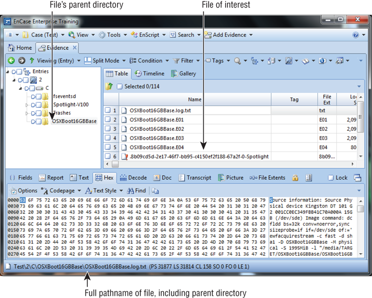
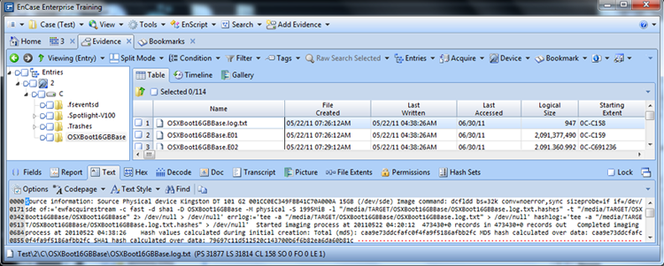
Directory entry raw data can be viewed, analyzed, and bookmarked in EnCase. For any file of interest, determine its parent folder, and place that parent folder in the table pane, placing focus on it by highlighting it. Figure 2-11 shows how to determine the parent folder for file of interest. The parent folder for the file of interest is OSXBoot16GBBase. Figure 2-12 shows this folder in the table pane and highlighted. In the view pane, choose the text. FAT directory entries in the view pane, shown also in Figure 2-12, will appear in red when viewed in EnCase.
Figure 2-11: File of interest and its parent directory. Note that the arrows show the linkage between the file (right arrow), its parent directory shown in the full path (down arrow), and its parent directory (left arrow).
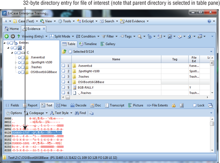
The entries shown in Figure 2-12 are displayed with 32 bytes per line. Since each entry is 32 bytes in length, each directory entry sits on a line by itself, making the data easy to see and analyze. This view didn’t magically appear; rather, it was created using EnCase’s Text Styles feature. The feature is accessed by following these steps:
1. Select Text Style tab under the Text view.
2. From the drop-down menu, choose Text Styles.
Figure 2-12: Directory entries in bottom pane shown in red of parent folder selected in right pane
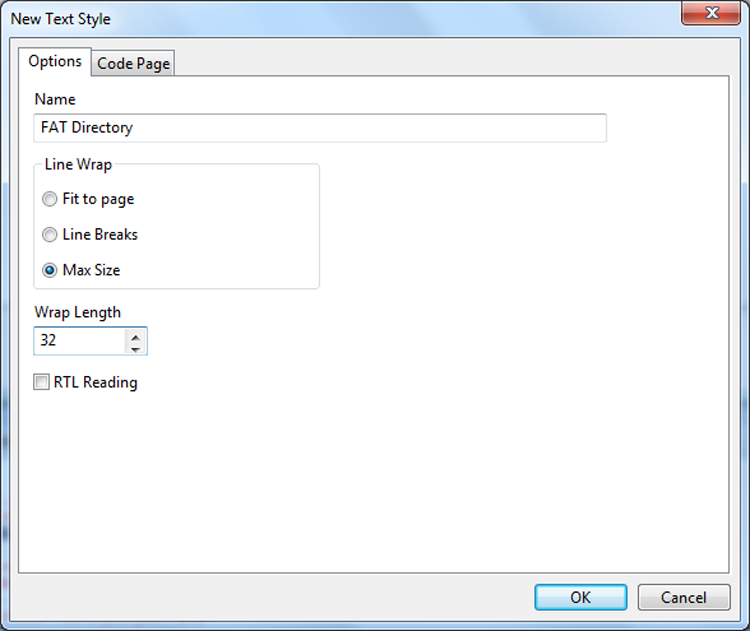
3. Click New and name it FAT Directory.
4. Choose Max Size and set the Wrap Length to 32, as shown in Figure 2-13.
Figure 2-13: Creating a custom text view for 32-byte directory entries
5. On the Code Page tab, select Other, and then select ISO-6937 or its nearest equivalent for the code page.
6. When done, click OK, and select your newly-created code page for viewing directory entries.
When you use this custom view, each of your directory entries will appear on a separate line.
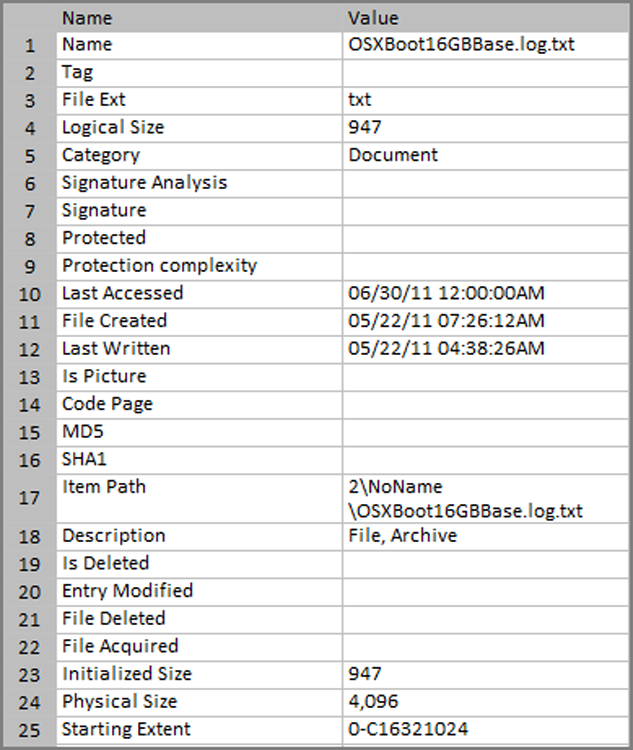
At this point, you could examine directory entries of interest for the selected parent folder. You could bookmark individual byte values within any directory entry using the byte offsets and descriptors in Table 2-3. Although very precise and demonstrative of your forensic prowess, it is painstakingly slow and tedious work. Alternatively, if you were to “sweep” the 32 bytes making up the directory entry, bookmark it as raw text, go to the bookmark view, select the Decode tab, and for a view type choose DOS Directory Entry under the Windows folder, EnCase would decode the information for you and allow you to have the information in a bookmark, as shown in Figure 2-14 and Figure 2-15. In Exercise 2.1, you use EnCase to decode this information for you.
Figure 2-14: A 32-byte directory entry, selected, bookmarked, and viewed as a DOS directory entry. EnCase decodes the directory entry information and places it in a bookmark.
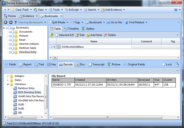
Figure 2-15: EnCase table view showing attributes from a directory entry that match information decoded in Figure 2-14
Exercise 2.1
Viewing FAT Entries
In this exercise, I will show you how to locate and view FAT directory entries. All you need to follow along is any device formatted with FAT.
1. Preview a USB thumb drive (any FAT version) by turning on the write-protect switch and mounting it in Windows. (Write-protecting your media is always a best practice but is not necessary for this exercise! Since EnCase now has FastBloc Software Edition included, you can practice best practices by write blocking; we’ll show you how.)
2. Launch EnCase (dongle required), and open a new case in EnCase, accepting the default values.
3. With a case open within EnCase Forensic (EnCase), select Tools > FastBloc SE (see Step 26). Select your write block mode and insert your thumb drive into the USB port. Write Blocked is the default mode and caches the attempts to write to the drive. Write Protected does not cache the attempts to write to the drive. After the media is placed into the USB port and it is recognized by the operating system, a pop-up window will appear, indicating that the media is connected and the status of the device. Select Close.
4. Click Add Evidence; in the screen that follows, choose Add Local Device.
5. In the screen the follows, accept the defaults and click Next. Locate your USB drive, place a blue check next to it, click Next, and then click Finish. Your thumb drive should be visible in the left pane as a device. Make certain the file system is visible.
6. Find a file of interest in a folder somewhere. Note carefully this file’s parent folder and path to that folder. You want to put the parent folder in the table pane. To do this, place the parent folder’s parent in the tree pane. If its parent is the root, then place your focus on the root level in the tree pane. When you see the parent folder of your file in the table pane, place your cursor on that parent folder in the table pane. The data for that parent folder is now in the view pane. In the view pane, select the Text View tab. The data for this parent folder should be in red.
7. You’ll see your data in red, but it is not formatted into nice 32-byte-wide entries. Let’s fix that.
8. In the view pane, under the Text tab, you’ll see Text Style with a black triangle, indicating a drop-down menu. From this drop-down menu, choose Text Styles.
9. From the resultant Edit Text Styles screen, choose New.
10. Use the same settings we used earlier in Figure 2-13 (Name: FAT Directory, Line Wrap: Max Size, and Wrap Length: 32) On the Code Page tab, use the ISO-6937 or its nearest equivalent.
11. Under View, choose Text Styles. In the left pane, right-click at the root level of the folders, and select New Folder.
12. Name the new folder custom.
13. Place your cursor on the custom folder, right-click, and choose New.
14. You are given a pane to create a new text style. Use the settings in Figure 2-13. On the Code Page tab, select Other, and select Latin 9 (ISO) for the code page.
15. When done, click OK.
16. From the Text Style drop-down menu, choose your newly created text style to apply it.
17. Go back to the table pane, and locate your parent folder in the right pane.
18. Click it in the table pane to view its contents in the view pane. Make sure you have the text view in the bottom pane. You should see your entries in nice 32-byte rows.
19. With your cursor, select the data for the 32-byte entry for your file of interest, as shown in Figure 2-12.
20. Right-click the selected 32-byte entry, choose Bookmark Data, and select the raw text as the type. If you like, you can create a new directory to contain this information, naming it something such as Directory Entry.
21. Under View, choose Bookmarks.
22. In the bottom section of View pane, go to the Decode tab.
23. In the left pane, you’ll see View Types. Under Windows, choose DOS Directory Entry, and the results will be displayed in the right pane.
24. Use this technique to bookmark directory information for a directory entry whose starting cluster is overwritten and in use by another file.
25. After previewing or acquiring the USB device, it is necessary to remove the USB and then turn off the FastBloc SE. First, remove the USB device from the computer.
26. Turn off FastBloc SE as a running process by accessing Tools > FastBloc SE. In the resulting menu, click Clear All. In the Plug and Play dialog box, it will ask, “Remove write-blocking for all devices on all channels?” Click Yes.
Another alternative for bookmarking directory entry information is to simply bookmark a file of interest and choose the various directory entry attributes to show in the resulting report, as shown in Figure 2-16.
Figure 2-16: Bookmark of file of interest with directory entry data showing in the report
![]()
Bookmarking the file and showing its directory attributes in the report is the method most commonly used to report this information. However, you can’t use this method when the file has been deleted and its starting cluster is in use by another file. EnCase is showing you the directory entry for such a file, but has no data to go with it as it is in use by another file. Any attempt to bookmark such a file will actually bookmark the file that has overwritten the data. When you encounter such a situation, having the knowledge and skills to bookmark the “raw data” is most useful!
The Function of FAT
Thus far, we have thoroughly dissected the physical features of the FAT file systems and delineated its underlying structures. While examining these structures, some of the functions started to emerge. In the following sections, I’ll describe how those structures function in detail as they interact with the operating system to read, write, and delete files.
From the previous discussions, you understand that the purpose of the FAT is twofold. First, whenever a file or directory’s contents exceed one cluster, FAT tracks the sequence of clusters that constitute that file or directory. Second, FAT tracks which clusters are available to be used by the operating system, marking bad clusters so they won’t be used, and ensuring that clusters allocated and in use by files and directories aren’t overwritten.
How a File Is Stored
Also from the previous discussions, you understand that the purpose of the directory entry is to track every file and directory in a partition. It does so by storing its status, its name, its starting cluster, and its length in bytes, as well as other file metadata or attributes. Let’s now examine how those functions interact with our operating system.
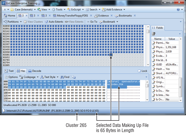
The first task is discovering what takes place during the simple act of reading a small file that is contained within one cluster. When the operating system calls for a file to be read, it is called by the filename and path. The path leads to the filename stored in the directory entry. It is the information stored in the directory entry that allows the operating system to begin to locate the data that constitutes this file. The filename for our example will be autorun.inf, which is located in a folder named New Report, which in turn is contained in the root directory of a FAT16 partition. The operating system looks in the parent folder and reads the directory information. Figure 2-17shows the information contained in the directory entry.
According to the directory entry, autorun.inf starts in cluster 2065 and has a size of 65 bytes. The operating system goes to cluster 2065 and starts to read the data, knowing its length is 65 bytes. After reading 65 bytes of data it stops, because the end of the data for the file has been reached. Any other data in the cluster is ignored since it is not part of the file. The file’s logical size is 65 bytes. A file will also have a physical size, which is the size of the clusters it occupies. Since it occupies one cluster (in this case a cluster contains only one sector), its physical size is 512 bytes.
Figure 2-18 shows the FAT entry for cluster 2065. (Each two-byte array represents one cluster in FAT16; thus, the two-byte array at file offset 4130 represents cluster 2065.) Its value is 0xFFFF, which for a FAT16 partition means that cluster is marked as end of file (EOF) since it is greater than 0xFFF8. This particular FAT16 partition uses one sector to constitute one cluster. One cluster will therefore hold 512 bytes of data before requiring an additional cluster, and thus 65 bytes fit easily in one cluster. Figure 2-19 shows cluster 2065, which contains the file’s data with 65 bytes selected.
Figure 2-17: Directory information for the file to be located and read in the example
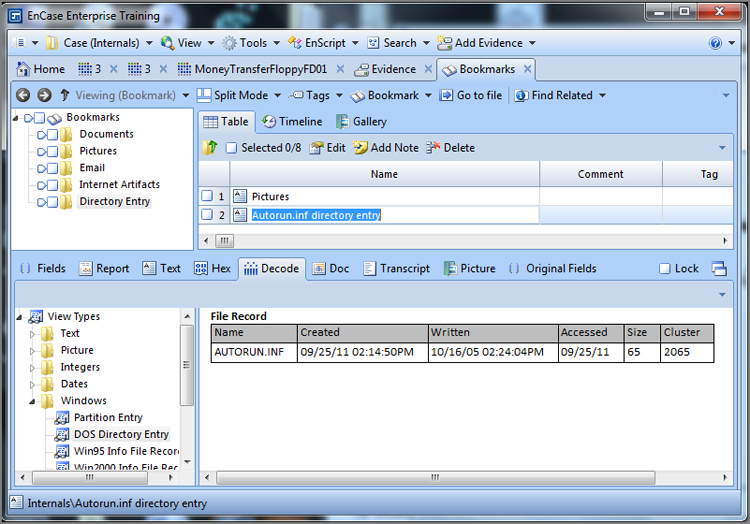
Figure 2-18: FAT entry for cluster 2065, showing the cluster marked as EOF
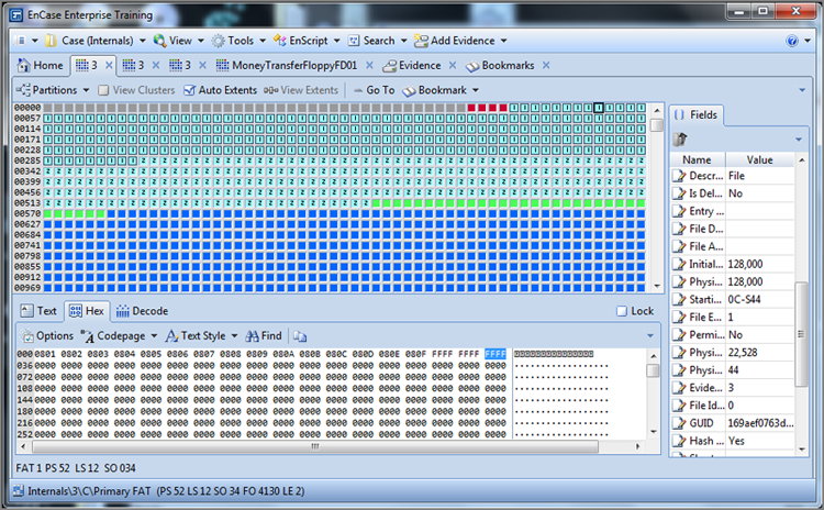
Figure 2-19: 65 bytes of data found in cluster 2065 that constitute the file autorun.inf
In the previous example, the data was contained in one cluster. In our next example, the data will not fit in one cluster and will span several clusters. When this happens, the FAT is necessary to link together the clusters. Let’s see how it actually works with real data.
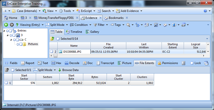
Figure 2-20 shows the file DSC00088.JPG having a starting cluster of 2 and a length of 512,848 bytes. You know that each cluster consists of one sector on this particular partition, and therefore one cluster can hold 512 bytes. To find out how many clusters a file will occupy, you divide the file size by the number of bytes in a cluster or, in this case, 512,848 bytes divided by 512 bytes per cluster, which equals 1,001.6 clusters (and some change). Since partial clusters are not allowed, this file will require 1,002 clusters to hold its data. You will expect the file to completely occupy all of the first 1,001 clusters (1,001 × 512 = 512,512 bytes) and the first 336 bytes of the last cluster in the chain (512,848 total bytes - 512,512 stored in first 1,001 clusters = 336 bytes). To check this reasoning and the math, EnCase has a File Extents tab. By selecting the file of interest in the table pane, details concerning this file are viewed in the bottom or view pane. Various tabs are available in the view pane, and one of them is the File Extents tab. Choose this tab, and the file extents for the selected file will display. Figure 2-21 shows the file extents for the file in our example, and when choosing the File Extents tab in the left pane, the right pane returns the File Extents information for the file.
Figure 2-20: File DSC00088.JPG has a starting cluster of 2 and a file length of 512,848 bytes.

Figure 2-21: The File Extents tab shows DSC00088.JPG starts at cluster 2 and occupies 1,002 clusters and the same number of sectors since one cluster in this case is one sector.
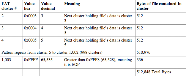
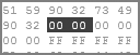
If you go to the FAT entry for cluster 2, since you know the file spans many contiguous clusters, you would expect cluster 2’s entry to tell you where to find the next cluster for the file. Figure 2-22 shows the entry for cluster 2 as 0x0003, which is decimal value 3, meaning that cluster 3 is the next cluster in the chain. Looking at cluster 3, you can see it has a value of 0x00004 (decimal 4), meaning the next cluster in the chain is 4. Looking at cluster 4, you’ll find it has a value of 0x0005 (decimal 5). Because this file occupies contiguous clusters (not fragmented), this pattern will persist until you reach the FAT entry for cluster 1,003, the last cluster in the chain. Figure 2-23 shows the FAT entry for this cluster. Looking at this entry, you’ll find it has a value of 0xFFFF, meaning it is the EOF. Since this is the last cluster in the chain, you can expect the file to end there and to be marked as EOF. Table 2-7 reinforces and explains in chart form what you see in the raw data.
Figure 2-22: The FAT entry for cluster 2 shows a value that points to cluster 3, which is the next cluster in the run.
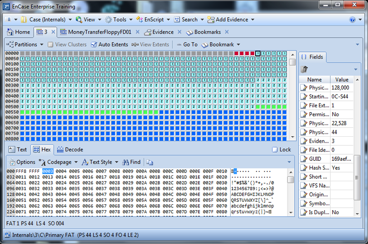
Figure 2-23: The FAT entry for cluster 1003 is highlighted. Its value indicates it is an end-of-file marker.
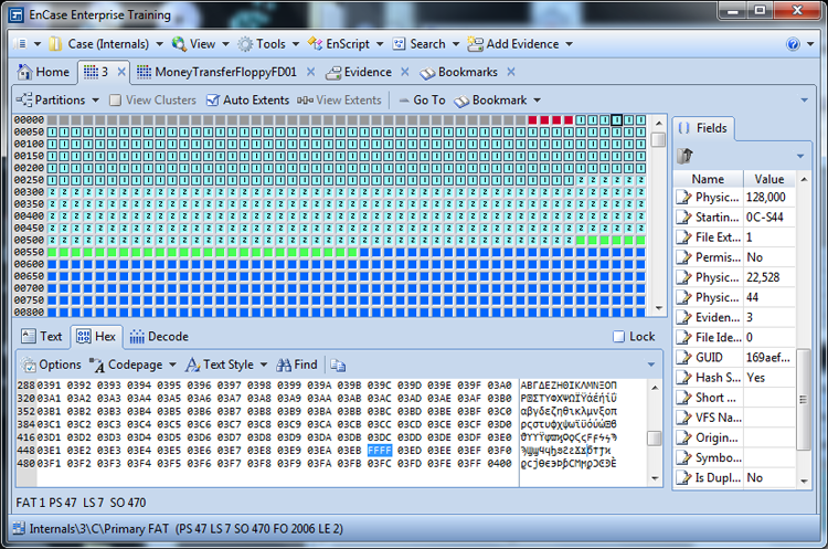
Table 2-7: FAT entries for file DSC00088.JPG
Now that you understand how the directory entries work in conjunction with the FAT to read files and have analyzed this process using raw data in an actual FAT, writing a file is just an extension of what you already know. To get you started, you will use the values shown in Table 2-8 and Table 2-9 as your hypothetical FAT and directory entries to write a file.
Table 2-8: File Allocation Table (FAT16: 1 cluster = 8 sectors = 4,096 bytes)

Bold numbers indicate cluster numbers (they don’t exist in a real FAT!)
E = End of file, 0 = Available, B = Bad cluster
Remember that the first addressable cluster is cluster 2, but the FAT array starts with entries for cluster 0 and cluster 1. The values for these two entries do not relate to cluster usage but are used for other “housekeeping” chores as already described.
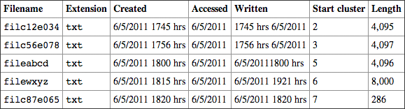
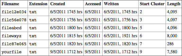
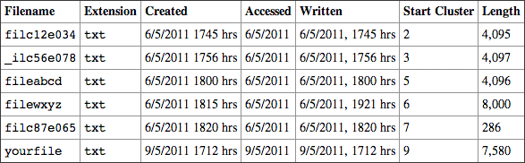
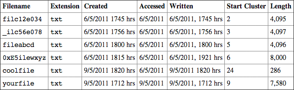
Table 2-9: Table of directory entries
To summarize the FAT (Table 2-8) and its corresponding directory entries (Table 2-9), the following are true:
· filc12e034.txt is 4,095 bytes in length and starts with cluster 2. Because it fits within a cluster (a cluster holds 4,096 bytes), only one cluster is needed, and the entry in the FAT for cluster 2 is marked as EOF.
· filc56e078.txt is 4,097 bytes in length and starts with cluster 3. Because it exceeds one cluster by one byte, it requires a second cluster to hold its contents. The FAT entry for cluster 3 is 4, meaning that cluster 4 holds the one byte needed to hold the data. As the data ends in cluster 4, cluster 4 contains the EOF marker.
· fileabcd.txt is 4,096 bytes in length and starts in cluster 5. Because its contents fit exactly in one cluster, no other clusters are needed, and cluster 5 is marked as EOF.
· filewxyz.txt is 8,000 bytes in length and starts in cluster 6. Eight thousand bytes divided by 4,096 bytes (the bytes in one cluster) is 1.95, meaning this file will take two clusters to hold its data. You would expect the entry for cluster 6 to contain the value for the second and final cluster, which is cluster 8. The entry for cluster 8 is marked as EOF. This file is fragmented, meaning its data is not contained in contiguous clusters, since its data is contained in cluster 6 and 8. Cluster 7 holds data for another file.
· filc87e065.txt is 286 bytes and starts in cluster 7. Its contents fit easily in one cluster, and cluster 7 is marked as EOF.
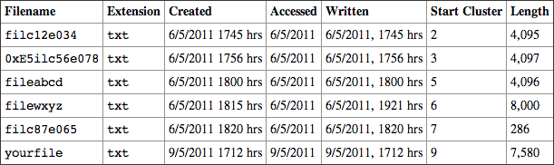
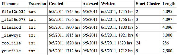
To write a file on this FAT16 file system, the file is given a name either by an application or by the user. Say you create your first file and call it yourfile.txt. This file has a length of 7,580 bytes. You could write this file using Table 2-8 and Table 2-9 as the starting point. The changes resulting from adding the hypothetical file will be reflected in Table 2-10 and Table 2-11.
Say the operating system first seeks an available cluster to which to write the data. Cluster 9 is available and will be the starting cluster for our data. Because this file will require two clusters, the operating system seeks the next available cluster. Because cluster 10 is marked Bad, cluster 11 is the next available. Thus, the operating system stores the data in clusters 9 and 11, marking the FAT entry for cluster 9 with the value for cluster 11, and cluster 11 is marked as EOF. See these entries in Table 2-10. A directory entry is written in the appropriate parent directory indicating the file’s name, starting cluster, length, and other metadata or attributes. See Table 2-11 for this entry. Because this example file is contained in two noncontiguous clusters (9 and 11), it is a fragmented file.
Table 2-10: File Allocation Table (FAT16: 1 cluster = 8 sectors = 4,096 bytes)
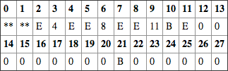
Table 2-11: Table of Directory Entries
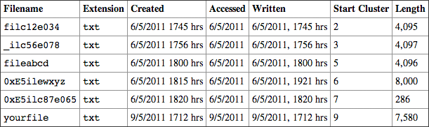
The first character of the file or directory name in a directory entry has a name and purpose. It is called the status byte. When in use by a file or directory, its purpose is somewhat obscured, because it is seen simply as part of the file or directory name. When a file or directory is deleted, its purpose becomes clear; the first character of the file or directory is changed to 0xE5 to signify to the operating system that the entry is deleted. This causes the OS to ignore the file and not display it to the user. Aside from making changes to the FAT to mark the clusters as unallocated, that is all there is to deleting a file. Let’s delete a file in our FAT16 file system and see how it works.
The Effects of Deleting and Undeleting Files
Using Table 2-12 and Table 2-13, delete filc56e078.txt. To do so, simply change the first character of the filename in the directory entry to 0xE5. In the hypothetical table, the 0xE5 takes up four characters, but in a real system, 0xE5 is one byte, as was the character it replaced. In a real directory entry, f, which is 0x66, is replaced by 0xE5. To complete the deletion, go to the FAT entry of the file’s starting cluster, which is cluster 3. Cluster 3 contains a value of 4, which is noted by the OS. Cluster 3 is marked with a 0, making it available for allocation. Cluster 4 contains an EOF, and the OS knows this is the end of the cluster sequence, so it marks it with a 0, making it available for allocation, and then stops. The file is deleted as far as the operating system is concerned. Aside from the first character of the directory, the remaining 31 bytes are untouched. The data in clusters 3 and 4 remain untouched. Because clusters 3 and 4 are marked with zeros, they are available to hold the contents of another file, and thus can be completely or partially overwritten. As they stand, however, they are easily and completely recoverable.
Table 2-12: File Allocation Table (FAT16: 1 cluster = 8 sectors = 4,096 bytes)
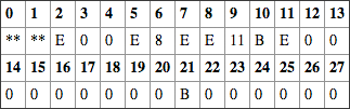
Table 2-13: Table of directory entries
To undelete or recover a file, you simply reverse the process by which it was deleted. In Tables 2-14 and 2-15, undelete this file. You start the process by going to the directory entry. You change the 0xE5 to the original character if known or a best guess if unknown, or you use some standard character, such as an underscore. If the file has a long filename and its entries are intact, the original character can be derived from that source. In this example, change the first character to an underscore character (see Table 2-15).
The next step in the process is to go to the FAT entry for the starting cluster for this file (Table 2-14), which from the directory entry you know to be 3. This file uses two clusters, so the value that must be entered for cluster 3’s entry must be the next cluster in the chain. The next available cluster after cluster 3 is cluster 4. Thus, a value of 4 is entered for cluster 3, and an EOF mark is made for cluster 4’s entry. At this point, the file has been successfully recovered. This is the basic manner in which EnCase will recover files automatically for you.
Table 2-14: File Allocation Table (FAT16: 1 cluster = 8 sectors = 4,096 bytes)
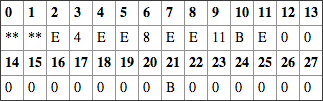
Table 2-15: Table of directory entries
The undelete process is not perfect. The file filewxyz.txt is fragmented, occupying two noncontiguous clusters, which are clusters 6 and 8. This file has been deleted in Table 2-16 and Table 2-17. The first character of the name in its directory entry has been changed to 0xE5, and the FAT entries for clusters 6 and 8 have been changed to 0, making them available for allocation by the system.
The file filc87e065.txt occupies a single cluster, which is cluster 7. This file has also been deleted, and that deletion is reflected in Table 2-16 and Table 2-17. The first character of the name in its directory entry has been changed to 0xE5, and the FAT entry for cluster 7 has been changed to 0, marking it as available for allocation by the system.
Table 2-16: File Allocation Table (FAT16: 1 cluster = 8 sectors = 4,096 bytes)
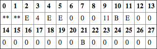
Table 2-17: Table of directory entries
Clusters 6, 7, and 8 are marked with zeros, with 6 and 8 holding the data for what used to be filewxyz.txt and cluster 7 holding the data for what used to be filc87e065.txt. Directory entries for these two files have had their status bytes changed to 0xE5, telling the operating system that these files are deleted and to ignore them. The files are both deleted as far as the operating system is concerned.
As with any busy operating system, data is constantly changing, with data being overwritten nearly every time a new file or directory entry is written. If the directory entry for what used to be filc87e065.txt were overwritten, recovering filewxyz.txt could be problematic. Let’s see why by looking at Table 2-18 and Table 2-19.
Table 2-18: File Allocation Table (FAT16: 1 cluster = 8 sectors = 4,096 bytes)
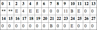
Table 2-19: Table of directory entries
With the directory entry for filc87e065.txt overwritten, there’s no way to tell that its former data was and still is in cluster 7. When it comes time to recover filewxyz.txt, you can restore the first character to an underscore and go to its starting cluster, which is cluster 6. You know it occupies two clusters, and without knowledge to the contrary, you can assume that the next available cluster is the next cluster in the series. Thus, when you recover the clusters, you are recovering clusters 6 and 7, not 6 and 8, which are the correct clusters. The data in cluster 6, the starting cluster, is correct, but the data in cluster 7 belongs to a different file. The entry, after recovery, for cluster 6, is 7, and cluster 7 contains the EOF marker. Table 2-20 and Table 2-21 show this erroneous recovery.
Table 2-20: File Allocation Table (FAT16: 1 cluster = 8 sectors = 4,096 bytes)
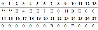
Table 2-21: Table of directory entries
The method of recovery you just employed manually is the same logic and method used by EnCase and other data recovery software. The directory entry gives only the starting cluster. The second cluster in the chain is assumed to be the next unallocated cluster after the starting cluster. The third is assumed to be the next unallocated cluster after that one, and so forth, until the number of clusters holding the data is reached. You can see the error that occurred with a two-cluster file. With extremely large files that become fragmented on busy systems, the potential for errors in recovering files is significant.
Your best chances for successful recovery will be when fragmentation is minimal and the deletion was recent. When you have an erroneous recovery, the error will usually stand out. If it is an image, chances are you’ll see a partial picture. If it is a web page, you’ll see it begin as HTML code and suddenly change to something else, typically binary data. When this occurs, you’ll understand what has happened and can explain why. Partial recovery is better than no recovery!
When EnCase recovers a deleted file, it will check to see whether the deleted file’s starting cluster is in use by another file. If not, it will recover the data by the previous method. If the starting cluster is in use by another file, it will report this as an “overwritten file.” In the right pane, you are looking at the information contained in the deleted file’s directory entry. The bottom pane contains the data for the file that overwrote the deleted file’s starting cluster. As previously mentioned, an attempt to bookmark an overwritten file will result in bookmarking the file and data that overwrote that file. It may be possible to manually recover some data in the second and subsequent clusters of an overwritten file.
Slack Space
When I was discussing logical file size and physical file size, I mentioned that the operating system ignored the data in the cluster after the logical file. Forensically, however, you don’t want to ignore that data because it can contain valuable evidence. The data between the end of the logical file to the end of the last cluster allocated to the file is called slack space. Slack space will usually contain data from files that used this space before, making it a rich depository of evidence.
Slack space is actually composed of data from two different sources. When data is written to media, it is written in blocks of 512 bytes or one sector. If only one byte of actual file data is to be written, the system must also write another 511 bytes such that it writes 512 bytes. Before Windows 95B, the “extra” data or filler was randomly taken from slack and caused many security concerns. With Windows 95B, that filler data became zeros. Because of its history, the portion of the slack space from the end of the logical file to the end of the sector (not the cluster) was called RAM slack. More recently, the term sector slack is also applied, and both refer to the same portion of the slack space. The remainder of the slack, from the end of the last sector containing the logical file until the end of the cluster, is called file slack. The entire slack space, comprising both RAM or sector slack and file slack, is shown in the default color of red when viewed in EnCase.
In Figure 2-24, the data in the logical file appears in the default color of black. When the logical file ends, EnCase displays the rest of the characters in red. At the beginning of the red characters, you can see that they are all 0x00 (RAM or sector slack) until the sector boundary is reached, at sector #511. In this example, I have selected the entire range of RAM slack (363 bytes) to make it more visible. After the sector boundary, what’s left is data remaining from files that were deleted, which is the file slack.
Figure 2-24: Slack space will appear in red. Windows Vista and Windows 7 still leave slack space evidence for the examiner!
Directory Entry Status Byte
Before I conclude the discussion of FAT file systems, there’s one more important point to cover. The directory entry status byte (the first byte of the 32-byte directory entry), as you have seen it used thus far, either has contained the first character of a valid file or directory name or has contained 0xE5 to indicate a deleted file or directory. It can contain a few other values that have special meaning.
Believe it or not, if you wanted to have the first character of a file as hex E5, you’d need the value 0x05. Also, if the first byte contained the value of 0x00, that means the entry is not used and entries beyond this point are not searched. However, the most important value for the forensics examiner, of the ones not yet covered, is that of 0x2E or 0x2E2E. Most may recall it more affectionately as the “dot double dot” signature for a directory, as shown in Figure 2-25.
Figure 2-25: Classic “dot double dot” directory signature
When the value of the first directory entry line begins with 0x2E, or “dot,” it denotes that it is a directory entry and the “dot” points to itself. The second directory entry line that follows will begin with 0x2E2E, or “dot dot.” This entry points to its parent directory. If you are at a command prompt and type cd.., you will change into the parent directory from where you were. In the “dot dot” line, the value contained in the “starting cluster” (byte offsets 26 and 27) will be that of the parent directory for the directory in which you currently are, as shown in Figure 2-26. If that value is 0x00, the parent directory is in the root directory, as shown in Figure 2-27.
Figure 2-26: Parent directory’s starting cluster at byte offsets 26 and 27
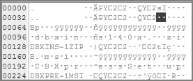
Figure 2-27: Same value in hex as it is hex 00. The parent of this directory is in the root directory.
The importance of understanding the “dot double dot” directory signature is recognizing it when you see it but also understanding its structure. Not all deleted directories are going to be shown initially by EnCase. You can instruct EnCase to recover folders, at which time it will search for folders in the unallocated clusters of the partition looking for this signature, and will then recover anything that is recoverable. If you are asked questions on the exam about how directories are structured or recovered, understanding these concepts is extremely important to establishing your credibility as a forensics examiner.
NTFS Basics
Another file system used by the Windows operating system, starting with Windows NT, is New Technology File System (NTFS). NTFS, compared to the FAT file system, is more robust, providing stronger security, greater recoverability, and better performance with regard to read, write, and search capabilities. Among other features, it includes support for long filenames, a highly granular system of file permissions and access control, and compression of individual files and directories. Accordingly, it is a far more complex file system. Covering it with the level of detail I have afforded the FAT system would not be feasible. Therefore, our purpose here is to provide a brief overview.
NTFS (version 1.0, also dubbed NT3.1) first rolled out in August 1993 with Windows NT. It went through two more iterations up through 1996 (versions 1.1 and 1.2, also dubbed NT3.5, NT3.51, and NT4.0). Windows 2000 gave birth to version 3.0, also dubbed NTFS 5.0. With XP in the fall of 2001, version 3.1 was born and also dubbed NTFS 5.1. Still under version 3.1, Windows Server 2003 rolled out in 2003 with a NTFS 5.2; Windows Server 2008 and Windows Vista rolled out with NTFS 6.0. And finally Windows Server 2008 R2 and Windows 7 rolled out with NTFS 6.1.
Windows NT and 2000 provided NTFS as a formatting option, defaulting to FAT unless the user chose otherwise. Starting with Windows XP, the default format is NTFS. Thus, newer Windows systems will mostly use NTFS, but FAT will still continue to coexist with NTFS (it is used on other forms of media, as discussed earlier).
From the previous analysis of file systems, you know that, regardless of their name, they must perform certain basic functions for the system:
· Track the name of the file (or directory)
· Track the point where the file starts
· Track the length of the file along with other file metadata, such as date and time stamps
· Track the clusters used by the file (cluster runs)
· Track which allocations units (clusters) are allocated and which are not
NTFS does all these things and more. An NTFS partition is identified as such, initially at least, by an entry in the partition table of the MBR. From Chapter 1, “Computer Hardware,” you know that Windows requires the partition to be properly identified in the partition table in order for Windows to mount it. When the NTFS partition is formatted, the VBR for NTFS is created and 16 sectors are reserved for its use, but typically only 8 are used for data. Bytes 3-6 of the first sector of the VBR will be “NTFS.” Recall that FAT32 stored the backup of its VBR in the reserved area at the beginning of the volume. By contrast, NTFS stores its backup copy in the last sector of the partition.
In an NTFS partition, unlike FAT, all the important file system data is contained in actual files. NTFS uses many system files, but at the very heart of the NTFS system are $MFT (master file table) and $Bitmap. $MFT is similar to the directory entry in FAT, and the $Bitmap is similar to the FAT1 and FAT2 in FAT.
$Bitmap is a file that contains one bit for each cluster in the partition. It tracks allocation only and does not track cluster runs. If a cluster has a 0 in $Bitmap, that indicates it is available for use by the system. If a cluster has a 1, the cluster is allocated to a file. It is a simple system.
$MFT is a database with an entry for every file and directory in the partition, including an entry for itself. Each entry is fixed in length and is almost always 1,024 bytes. Each entry has a header (FILE0), which is followed by series of attributes. Everything about a file is an attribute, including the data itself. If a file is small, sometimes its data is stored within the $MFT and is called resident data. Cookie files are an excellent example of files that are almost always resident data. Typically the average maximum length for resident files is about 480 bytes. This varies with the type and length of the attributes in the $MFT. If a file can’t be stored in the $MFT, then it is stored in a cluster, and in place of the resident data, the cluster runs are stored.
When a file is deleted on an NTFS partition, a flag in the $MFT is set, indicating the file is not in use, and the allocated clusters are marked with 0s in $Bitmap, which means they are unallocated. In addition, the index buffer entry for the logical folder is deleted. Because the $MFT record is otherwise untouched, an accurate record of cluster runs is usually intact, thus making recovery more reliable. The downside of recovering files in NTFS is that $MFT can grow but not shrink. As files are deleted, their $MFT records are efficiently and quickly overwritten, especially with XP.
Table 2-22 lists the major system files of the NTFS system along with a brief description of their functions.
Table 2-22: NTFS system files
|
MFT record # |
Filename |
Description |
|
0 |
$MFT |
Master file table; each MFT record is 1,024 bytes in length. |
|
1 |
$MFTMirr |
Contains a backup copy of the first four entries of the MFT. |
|
2 |
$LogFile |
Journal file that contains file metadata transactions used for system recovery and file integrity. |
|
3 |
$Volume |
NTFS version and volume label and identifier. |
|
4 |
$AttrDef |
Attribute information. |
|
5 |
$. |
Root directory of the file system. |
|
6 |
$Bitmap |
Tracks the allocation status of all clusters in the partition. |
|
7 |
$Boot |
Contains partition boot sector and boot code. |
|
8 |
$BadClus |
Bad clusters on partition are tracked with this file. |
|
9 |
$Secure |
Contains file permissions and access control settings for file security. |
|
10 |
$UpCase |
Converts lowercase characters in Unicode by storing an uppercase version of all Unicode characters in this file. |
|
11 |
$Extend |
A directory reserved for options extensions. |
![]()
New to NTFS, starting with Windows Vista, are Transactional NTFS and symbolic links. Transactional NTFS allows applications to group changes into a transaction. By making it a transaction, it is guaranteed that all the changes are made or none of them. Further, any applications outside the transactions will not see the changed data until it is committed. This process uses a Common Log File System (CLFS) to record the changes before they are committed, such that if a failure occurs, the system can be rolled back to a safe point. Symbolic links are often dubbed soft links. Symbolic links are resolved on the client side, not the server side. When symbolic links are shared, the target of the link is subjected to the same access controls as on the client. These links can be to files or directories.
![]()
“You Won’t Find Anything Because I Wiped the Hard Drive”
The superintendent of a local school district called to report that child pornography had been found on one of their computers. The school board had assigned a computer to the foreperson of a contractor hired to renovate their school. After the contractor was terminated and the computer returned to the school board, they discovered the computer contained images of child pornography. Instead of notifying law enforcement, the superintendent turned the computer over to a school board member, who was employed as a computer system administrator. According to the superintendent, the board member printed the images and provided them to the school board attorney. I quickly made arrangements to retrieve the printed images from the school board attorney and informed her of the possible ramifications of possessing images of child pornography.
I met with the school board member (who still had possession of the computer) and advised him as well of the possible ramifications of his actions. When I asked for the computer, he said, “You won’t find anything because I wiped the hard drive.” He said his intentions were to remove any evidence of child pornography (since he had already preserved the photos in printed form) so the computer could be reused. When I asked what method he used to wipe the contents of the hard drive, he reminded me of his credentials and said he had used a wiping utility that he commonly uses at his job. Nonetheless, I received permission from the superintendent to examine the computer and took possession of it.
As I started the examination, I immediately observed that the hard drive did not contain a logical volume with a directory structure. However, I noticed actual data within the sectors, not just a repeat of some arbitrary hexadecimal value, which would indicate that the drive had indeed been wiped. I then pointed to physical sector 63 and observed the text “NTFS” in its complete context; in hexadecimal it was “EB 52 90 4E 54 46 53,” which would indicate an NTFS partition. Why physical sector 63? At that time, I could not tell whether it was ingrained in me to automatically go to physical sector 63 or whether I actually knew that the first 63 sectors, physical sector 0-62, were reserved for the MBR and that the next sector contained information about the partition. Regardless, I pointed EnCase to physical sector 63, right-clicked, chose Add Partition, and selected the option to rebuild an NTFS partition. The Add Partition feature interprets the selected sector as the beginning of a VBR and rebuilds the previously removed partition based on the information contained within.
Upon a successful recovery of the partition, I was able to provide a detailed explanation of how and when the noted images were obtained.
![]()
With Windows 7, a regular format will wipe! For years, Windows did not truly wipe data during the format process. However with Windows 7, a regular format will wipe. Fortunately, the default format option is Quick Format, which does not wipe. Keep that in mind if you are told that Windows 7 was used to “format.”
CD File Systems
When CDs first came out, as with many things, standards were lacking—and history has shown that a lack of standards can limit the growth of an industry or product. Several representatives of the CD industry and Microsoft met at the High Sierra Hotel in Lake Tahoe. The standard they published in 1986 for CD standards was aptly named High Sierra. Two years later in 1988 the International Organization for Standardization met and revised the High Sierra standard, calling it ISO 9660. ISO 9660 allowed for cross-platform capability for CDs between PCs, Unix, and Macintosh computers. Such universality wasn’t without a price, and ISO 9660 CDs had the following limitations at the Level 1 implementation:
· Only uppercase characters (A-Z), numbers (0-9), and the underscore were permitted in the file name.
· Names used the 8 dot 3 file-naming convention.
· Directory names could not exceed 8 characters and could not have extensions.
· Nesting of subdirectories was limited—no deeper than 8 levels.
· Files had to be contiguous.
Minor improvements to this standard were implemented. Level 3 interchange rules allowed (using the previous rule set as a base) 30 characters in the filename. Level 3 implemented another improvement to the Level 2 rule set by not requiring files to be contiguous.
Microsoft developed the Joliet extension of ISO 9660 with the advent of Windows 95. Joliet offers significant improvements over its ISO 9660 predecessor. With Joliet, files or directories can be 64 characters long (Unicode support), directories can have extensions, the 8-levels-deep subdirectory barrier was removed, and multiple-session recording was supported.
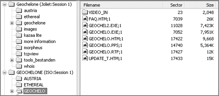
When examining a CD that was created with Joliet, you will see an ISO 9660 directory and a Joliet directory, as shown in Figure 2-28 and Figure 2-29. This won’t be visible in Windows, and can only be viewed on software designed to analyze CDs. With two separate directory structures pointing to the same data, operating systems that support Joliet can use that directory system and its features. Those that don’t support Joliet use the ISO 9660 with its limitations.
Figure 2-28: CD with both ISO 9660 and Joliet directory structures. Note the Joliet directory names.
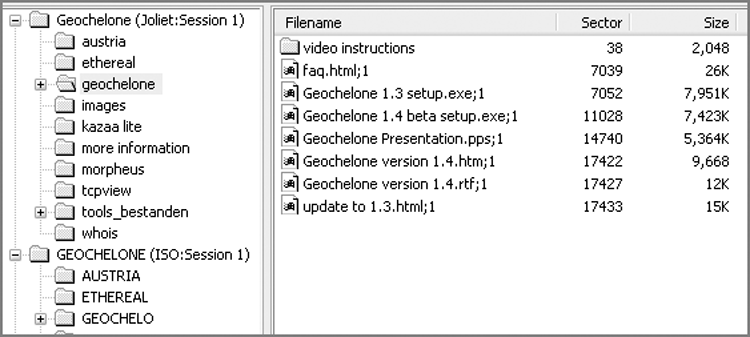
Figure 2-29: CD with both ISO 9660 and Joliet directory structures. Note the same directory names with ISO 9660 naming limitations.
Universal Disk Format (UDF) is a relative newcomer to the CD scene. UDF uses a technique called packet writing to write data in increments to CD-R/RW disks. UDF allows for 255 characters per filename, which is a significant improvement over Joliet. Roxio DirectCD is an example of packet-writing software that writes using the UDF format. Unless you have the driver installed, you can’t read a CD written with UDF, which often causes problems for examiners. Roxio provides a free driver at its website, which enables you to read a CD created in UDF. Another, less preferred option is to use DirectCD to close the session on a UDF CD. When this occurs, the filenames are converted to Joliet, and filenames that had a 255-character limit are truncated to 64.
Macintosh uses a native HFS format on its media and can use it on CDs, but HFS CDs can’t be read by PCs. The hybrid disc is often used to overcome this issue, creating both an HFS directory and a Joliet directory, both pointing to the same set of data and readable by both the Macintosh and PCs.
Much like the Joliet extension, the Rock Ridge extension was created for Unix, which naturally supported Unix file-system features. Rock Ridge can’t be read by PCs, but the basic ISO 9660 feature is present and read, and thus the Rock Ridge extensions are ignored when read by a PC.
Beginning with Version 5, EnCase supports CD images created by CD Inspector. You can use CD Inspector to examine CDs, including the “difficult” ones. CD Inspector provides an imaging utility that creates an image with a .zip extension. Those image files can be opened directly in EnCase. For this reason, many examiners prefer to use CD Inspector to examine and image problem CDs and rely on EnCase for analyzing the data.
exFAT
In 2006, Microsoft introduced the exFAT file system with Windows Embedded CE 6.0, and shortly thereafter it appeared in Windows Vista with Service Pack 1. It is a proprietary file system designed for flash media and is often dubbed FAT64. While it has many other new features, exFAT boasts a file size limit of 16 EiB (1 exbibyte = 260 bytes = 1,152,921,504,606,846,976 bytes). For years, FAT32 had imposed a file size limit of 4 GB. This huge file size limit was welcome news for forensic examiners needing to store large files on a robust file system that is compatible with many operating systems.
The following operating systems support exFAT as well:
· Windows XP and Windows Server 2003, running Service Pack 2 and with a special patch (KB955704)
· Windows Vista with Service Pack 1
· Windows Server 2008
· Windows 7
· Later versions of OS X Snow Leopard (10.6.5)
· All versions of OS X Lion support exFAT. This OS X support includes not only read and write functions, but the ability to create exFAT partitions as well.
· As of this writing, the Linux kernel lacks support directly for exFAT; however, progress is underway.
There are four major areas or regions of exFAT:
· The main boot region
· The backup boot region
· The FAT region (normally only FAT1 is found unless TFAT is configured and then FAT2 will be found)
· The data region
EnCase supports exFAT partitions and has done so since midway through EnCase 6. Figure 2-30 depicts an exFAT partition in the disk view of EnCase 7. The focus is on the first sector (Logical Sector 0) of the partition known as the volume boot record (VBR). You should immediately note the file system name EXFAT highlighted in the view pane at offset 3 and running 8 bytes. The main boot region starts at Logical Sector 0 and runs for 12 sectors, ending at Logical Sector 11. The backup boot region immediately follows starting at Logical Sector 12 and again running for 12 sectors. After the backup boot region is an unused region, followed by FAT1. The offset to the beginning of and length in sectors of FAT1 is defined in the VBR at offsets 80 and 84 (4 bytes each). The data area will follow the FAT region and will also be defined in the VBR. Table 2-23 sets forth the various fields and offsets of the exFAT volume boot record.
Figure 2-30: Disk view of exFAT file system. The focus is on the VBR. Note the file system name highlighted in the view pane.
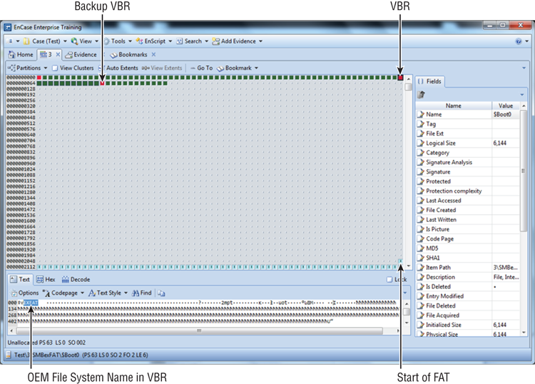
Table 2-23: Volume boot record: exFAT file system
|
Decimal offset |
Length |
Field description |
|
0 |
3 |
Jump code |
|
3 |
8 |
EXFAT: OEM file system ID |
|
11 |
53 |
Must be 0x00 |
|
64 |
8 |
Partition sector offset (will be zero for removable media) |
|
72 |
8 |
Total sectors in the volume |
|
80 |
4 |
Offset to beginning of FAT |
|
84 |
4 |
Physical size of FAT in sectors |
|
88 |
4 |
Offset to bitmap |
|
92 |
4 |
Allocation units in the volume (bit count) |
|
96 |
4 |
First cluster of the root directory |
|
100 |
4 |
Volume serial number |
|
104 |
2 |
File system revision number V.M (for example, 1.0) |
|
106 |
1 |
Volume flags |
|
107 |
1 |
Active FAT |
|
108 |
1 |
Bytes per sector (power of 2 - 29 = 512) |
|
109 |
1 |
Sectors per cluster (power of 2) |
|
110 |
1 |
Number of FATs (1 or 2, and only 2 if TexFAT is configured and in use) |
|
111 |
1 |
Used by INT 13 |
|
112 |
1 |
Percentage in use |
|
113 |
7 |
Reserved |
|
120 |
390 |
Boot program |
|
510 |
2 |
VBR Signature 0xAA55 |
The exFAT file system will see expanded use over time, while currently it is not all that commonly encountered. The following is a list of important concepts pertaining to exFAT:
· The exFAT file system uses 32-bit arrays within the FAT to describe cluster numbers and has a limit of 4,294,967,285 (232-11) cluster addresses.
· exFAT uses free space bitmaps to reduce fragmentation, as well as allocation/detection issues.
· Each cluster is tracked in the bitmap, and a single bit is used to denote the status of each cluster (1 = allocated and 0 = unallocated).
· When a file is created in an exFAT file system, the sequence of events may differ from that which occurs in a FAT file system. If the file is fragmented, the exFAT and FAT function in the same manner. If, however, the file is not fragmented, the FAT is not updated.
· The exFAT file system uses the FAT (or a linked list) to document data file fragmentation. There will be a flag in one of the directory entry records to indicate whether the FAT is being used to document the fragmentation of the file.
· The FAT in an exFAT file system does not track whether clusters are unallocated or allocated as it does in a FAT file system. Rather, the exFAT FAT will contain data indicating one of three possible conditions: pointer to the next cluster or fragment, end of file (FF FF FF FF), or no fragmentation being tracked (00 00 00 00). Remember, the bitmap tracks allocation in exFAT!
· Within the directory entries of exFAT, there are multiple 32-byte records with at least three for each directory entry. Each of these records will have an identifier byte. They are as follows:
· Directory Entry Record, which will have a Record ID of 0x85 and will contain attributes, the created timestamp, the last-accessed timestamp, and the last written timestamp.
· Stream Extension Record, which will have a Record ID of 0xC0 and will contain the logical size, starting extent, size of filename, CRC of filename, and flag that determines whether the FAT is being used to track the clusters allocated to the file.
· Filename Extension Record, which will have a Record ID of 0xC1 and will contain the filename in Unicode. Additional records will be added to accommodate longer filenames.
· When a file is deleted on an exFAT file system, regardless of fragmentation, the FAT is not zeroed out, because the FAT does not track allocation, since this function is carried out by the bitmap. The forensic import of this is that if the file was fragmented, the cluster runs are not destroyed upon deletion, which does occur with FAT file systems. Thus, fragmented files have a higher likelihood of successful recovery on exFAT file systems, so long as the clusters themselves have not be reused, which of course would result in overwriting FAT records.
· When a file is deleted on an exFAT file system, the first bit of the record identifier is changed from a 1 to a 0, which is strikingly similar to marking the first byte in a directory entry with 0xE5 on a FAT file system.
![]()
For those seeking an in-depth understanding of the exFAT file system, you should read the SANS paper entitled “Reverse Engineering the Microsoft Extended FAT File System (exFAT)” by Robert Shullich. You can find it at www.sans.org/reading_room/whitepapers/forensics/reverse-engineering-microsoft-exfat-file-system_33274.
Summary
This chapter explained the file systems used on Windows operating systems. Because the FAT file system is the most prevalent and has a long history, I covered its structure and function in great detail. The FAT file system works primarily with the directory entries and the FAT to read and write data on its partition. The FAT tracks cluster allocation and cluster runs in use by a file. The directory entries track the names of files and directories, along with their starting clusters and lengths. Using these basic features, files are read, written, and deleted. By reversing the deletion process, you learned how to recover deleted files.
I also covered the NTFS file system. At the heart of the NTFS file system are the master file table (MFT) and the bitmap ($Bitmap). The bitmap tracks only whether clusters are allocated. The MFT is similar to the directory entry in FAT, only much more robust. Everything about a file, including sometimes the data itself, is an attribute and stored in the MFT. If the data is small enough, it is stored as resident data in the MFT. If it is too large, it is stored in clusters, and the data runs are stored in the MFT.
You examined the various CD file systems and their history and features. ISO 9660 is the universal format that can be read by all platforms, but it has limitations. The Joliet extension of ISO 9660 contains expanded features for Microsoft platforms. Packet-writing software creates a UDF format that greatly enhances the length of filenames and allows for writing small amounts of data in increments. Its drawback is that it requires a driver to read on machines without the packet-writing software. To create universality, CDs are often written with multiple directory structures pointing to the same set of data. In this manner, an operating system can use the best directory it can support.
Finally, I covered Microsoft’s new file system, exFAT. This file system was created for flash media and provides for a maximum file size of 16 EiB. This file system has four main regions, which are the boot region, the backup boot region, the FAT region, and the data region.
Exam Essentials
Know the physical features of the FAT file system. Understand and locate the reserved area, the FAT, and the data area on FAT12/16/32 file systems. Understand how FAT12, FAT16, and FAT32 differ with regard to the physical features.
Be familiar with the volume boot record (boot sector). Know how to locate the boot sector on FAT12/16 and FAT32 file systems. Understand the data contained therein and its importance, particularly in the event a partition must be restored.
Understand the FAT and the directory entry. Be able to explain how files are read, written, and deleted using the FAT and directory entries. Know how files are recovered by reversing the process by which they were deleted and the limitations of that process.
Define the basics of the NTFS file system. Explain how the bitmap is used only to track cluster allocation and how the MFT is used to store file attribute information, including filename, starting cluster, cluster runs, and data length, among other attributes.
Be familiar with the exFAT file system. Know the maximum file size that is supported by this file system. Be able to name and locate the four major regions of this file system.
Review Questions
![]()
The word “FAT” applies to FAT12, FAT16, and FAT32 file systems, unless exFAT is specifically mentioned.
1. On a FAT file system, FAT is defined as which of the following?
A. A table consisting of master boot record and logical partitions
B. A table created during the format that the operating system reads to locate data on a drive
C. A table consisting of filenames and file attributes
D. A table consisting of filenames, deleted filenames, and their attributes
2. How does a corrupted sector located in the data area of a hard drive affect the corresponding cluster number on a FAT in a FAT file system?
A. It does not affect the corresponding cluster number on a FAT; therefore, the rest of the sectors associated with the assigned cluster can still be written to.
B. It does not affect the corresponding cluster number on a FAT; only the corrupted portion of the sector is prevented from being written to.
C. It does affect the FAT. The corresponding cluster number is marked as bad; however, only the corrupted sector within the cluster is prevented from being written to.
D. It does affect the FAT. The corresponding cluster number is marked as bad, and the entire cluster is prevented from being written to.
3. Which of the following describes a partition table?
A. It is located at cylinder 0, head 0, sector 1.
B. Is located in the master boot record.
C. It keeps track of the partitions on a hard drive.
D. All of the above.
4. Which selection keeps track of a fragmented file in a FAT (not exFAT) file system?
A. File Allocation Table
B. Directory structure
C. Volume boot record
D. Master file table
5. If the FAT, in a FAT file system, lists cluster number 2749 with a value of 0, what does this mean about this specific cluster?
A. It is blank and contains no data.
B. It is marked as bad and cannot be written to.
C. It is allocated to a file.
D. It is unallocated and is available to store data.
6. Which of the following is true about a volume boot record?
A. It is always located at the first sector of its logical partition.
B. It immediately follows the master boot record.
C. It contains BIOS parameter block and volume boot code.
D. Both A and C.
7. The NTFS file system does which of the following?
A. Supports long filenames
B. Compresses individual files and directories
C. Supports large file sizes in excess of 4 GB
D. All of the above
8. How many clusters can a FAT32 file system manage?
A. 2 × 32 = 64 clusters
B. 232 = 4,294,967,296 clusters
C. 2 × 28 = 56 clusters
D. 228 = 268,435,456 clusters
9. In a FAT file system, the FAT tracks the _____________ while the directory entry tracks the _____________ .
A. The filename and file size
B. The file’s starting cluster and file’s last cluster (EOF)
C. The file’s last cluster (EOF) and file’s starting cluster
D. The file size and file fragmentation
10. How many copies of the FAT does each FAT32 volume maintain in its default configuration?
A. One
B. Two
C. Three
D. Four
11. Which of the following is not true regarding the NTFS file system?
A. Data for very small files can be stored in the MFT itself and is referred to as resident data.
B. Cluster allocation is tracked in the $Bitmap file.
C. Data that is stored in clusters is called nonresident data.
D. Cluster allocation is tracked in the File Allocation Table (FAT).
12. A file’s physical size is which of the following?
A. Always greater than the file’s logical size
B. The number of bytes in the logical file plus all slack space from the end of the logical file to the end of the last cluster
C. Both A and B
D. None of the above
13. A directory entry in a FAT file system has a logical size of which of the following?
A. 0 bytes
B. 8 bytes
C. 16 bytes
D. One sector
14. Each directory entry in a FAT file system is ____ bytes in length.
A. 0
B. 8
C. 16
D. 32
15. By default, what color does EnCase use to display directory entries within a directory structure?
A. Black
B. Red
C. Gray
D. Yellow
16. What is the area between the end of a file’s logical size and the file’s physical size called?
A. Unused disk area
B. Unallocated clusters
C. Unallocated sectors
D. Slack space
17. What three things occur when a file is created in a FAT32 file system?
A. The directory entry for the file is created, the FAT assigns the necessary clusters to the file, and the file’s data is filled in to the assigned clusters.
B. The filename is entered in to the FAT, the directory structure assigns the number of clusters, and the file’s data is filled in to the assigned clusters.
C. The directory entry for the file is created, the number of clusters is assigned by the directory structure, and the file’s data is filled in to the FAT.
D. The directory structure maintains the amount of clusters needed, the filename is recorded in the FAT, and the file’s data is filled in to the assigned clusters.
18. How does EnCase recover a deleted file in a FAT file system?
A. It reads the deleted filename in the FAT and searches for the file by its starting cluster number and logical size.
B. It reads the deleted filename in the directory entry and searches for the corresponding filename in unallocated clusters.
C. It obtains the deleted file’s starting cluster number and size from the directory entry to obtain the data’s starting location and number of clusters required.
D. It obtains the deleted file’s starting cluster number and size from the FAT to locate the starting location and amount of clusters needed.
19. What does EnCase do when a deleted file’s starting cluster number is assigned to another file?
A. EnCase reads the entire existing data as belonging to the deleted file.
B. EnCase reads the amount of data only from the existing file that is associated with the deleted file.
C. EnCase marks the deleted file as being overwritten.
D. EnCase does not display a deleted filename when the data has been overwritten.
20. Which of the following is not true regarding the exFAT file system?
A. Cluster allocation is tracked in the File Allocation Table (FAT).
B. When a file is deleted, the corresponding entries in the File Allocation Table (FAT) are reset or zeroed out.
C. Cluster allocation is tracked in an allocation bitmap.
D. An entry in the FAT of 00 00 00 00 means that the FAT is not tracking allocation for this file.
All materials on the site are licensed Creative Commons Attribution-Sharealike 3.0 Unported CC BY-SA 3.0 & GNU Free Documentation License (GFDL)
If you are the copyright holder of any material contained on our site and intend to remove it, please contact our site administrator for approval.
© 2016-2026 All site design rights belong to S.Y.A.