EnCase Computer Forensics (2012)
Chapter 10
Advanced EnCase
EnCE Exam Topics Covered in This Chapter:
· Locating and mounting partitions (partition recovery)
· Mounting files
· Windows registry
· EnScripts and filters
· Base64 encoding
· EnCase Decryption Suite (EDS)
· Virtual File System (VFS)
· Restoration
· Physical Disk Emulator (PDE)
This book’s final chapter is a collection of advanced analysis concepts and tools. It begins with working with deleted partitions. I’ll rely heavily on concepts covered in Chapter 2 as I explain the MBR, the VBR, and recovered deleted partitions.
There are a large number of complex files that can be “mounted” within EnCase for further examination and analysis. In this chapter, I’ll describe the various ones supported, how they are mounted, and what to expect when they are mounted.
Among the files that EnCase can mount are the system registry files. A number of files comprise the system registry of the most current versions of Windows. I’ll discuss how the files are mounted and the various registry keys that are derived from those files. Because understanding the registry is an important forensic skill, I’ll explore some registry research techniques with the live Windows registry on a little-understood registry key. From that research, you’ll better understand that particular key and develop valuable registry research skills in the process.
Throughout the text I’ve made reference to and used some basic EnScripts. In this chapter, I’ll cover how to use the current EnScript feature set and its options.
Email seems to be a consistent factor in nearly every forensic examination. Email clients abound, and EnCase 7 provides support for most of the mainstream clients, with more under development. I’ll describe which clients are currently covered and how EnCase 7 mounts and displays various email databases.
While I’m on the topic of email, I’ll cover Base64 encoding, which is the most commonly encountered method for encoding email attachments. I’ll cover how EnCase handles it automatically as well as how to manually extract it from the unallocated clusters.
EnCase 4, 5, and 6 have optional modules that you can purchase. However, many modules that were heretofore options for an added cost are included as part of EnCase 7. The EnCase Decryption Suite (EDS) decrypts data and files encrypted with the Windows Encrypted File System (EFS). I’ll cover the basic features of this module.
There are two other modules now included: the Virtual File System (VFS) and the Physical Disk Emulator (PDE). VFS mounts the evidence file device as a file system so that it is available as a mounted volume in Windows. With this mounting, all data, including deleted folders and files, can be analyzed in Windows with third-party tools or Windows system tools. PDE is similar, but it mounts the evidence file device as a physical device in Windows. I’ll discuss the similarities and differences in the two modules and how you can use them to further your examinations.
The EnCase FastBloc Software Edition (SE) is now included with EnCase 7. I covered this module extensively in Chapter 4, so I’ll only briefly cover it in this chapter. EnCase 7 ships with another useful optional module called the CD-DVD module. By using this module, several features within EnCase can have their output written directly to a CD or DVD.
Occasionally you may need to restore an entire drive to boot and run the system as the suspect used it. That technique is called restoration, and I’ll cover that as well.
Locating and Mounting Partitions
In this section, I’ll make frequent references to concepts covered in detail in Chapter 2. If you aren’t comfortable with MBRs, partition tables, VBRs, partition types, physical and logical sector addresses, CHS, and tracks, you may want to reread that chapter or at least refer to it frequently to refresh your understanding.
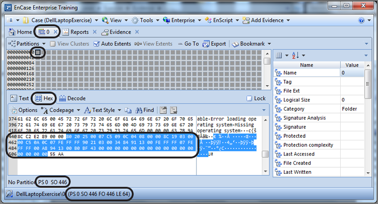
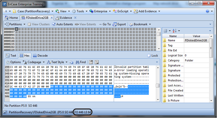
You should recall that the master boot record (MBR) is located at the first physical sector of a hard drive. Although it contains important boot code, it also contains the partition table, which can describe up to four partitions on that hard drive. The partition table consists of 64 bytes and starts in physical sector 0 at byte offsets 446 through 509. Each of four possible partitions is described by a 16-byte string.
Figure 10-1 shows the partition table in which sector 0, byte offsets 446 through 509, are selected. You should note that I’m working in the Disk view in the Table pane and in the Hex view in the View pane.
Figure 10-1: The partition table in sector 0 of the MBR type partition scheme is selected.
To have EnCase interpret or parse the information in the 64-byte partition table, we need only switch to the Decode view and choose the Partition Entry view type, as shown in Figure 10-2.
Figure 10-2: This is a 64-byte partition table selected and viewed as a Windows Partition Entry in the Decode view.
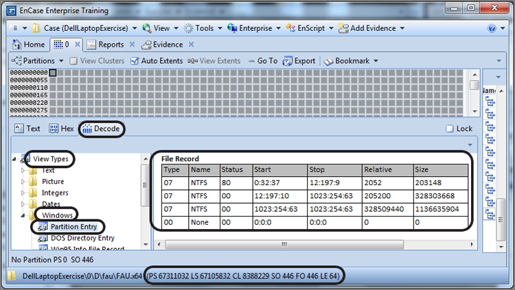
In this case, there are three partitions on this drive, and all three partitions are of type 07h, which is NTFS. This is shown in the first column. The first partition on this Windows 7 system is a 100 MB, hidden-system partition that handles the boot, and its status is 80h, which means the partition is the active, bootable partition. Using the legacy Cylinder Head Sector (CHS) system, the start point for the first partition is 0:32:37, and the stop point is 12:197:9. The more meaningful information follows the legacy CHS addressing, which is the starting sector (in the Relative column) and the size in sectors. The size of the first partition is 203,148 sectors (approximately 100 MB), relative to sector 2,052, which is the starting sector for the partition. If you add 2,052 to 203,148 and subtract 1, you arrive at 205,199, which is the sector number of the last sector in the partition. Since this is an NTFS partition, if you go to that last sector of the partition (sector 205,199), you will expect to find a backup copy of the VBR, and you do, as shown in Figure 10-3.
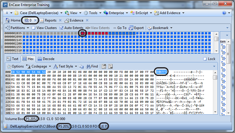
Since you know the starting sector of the partition from the partition table, you can easily go to that sector to view the first sector of the partition, which you have learned is the volume boot record (VBR). In this example, the first sector of the first partition is at sector 2,052. If you go to that sector, you will be at the VBR. Figure 10-4 shows the data found at sector 2,052, which is the VBR. The position indicator (GPS) confirms you are at physical sector (PS) 2,052. VBRs have headers or signatures that will eventually allow you to find them if the partition table entries are deleted. One of these signatures or headers is selected (first 7 bytes) in Figure 10-4. As you’ll probably recall from Chapter 2, the first 3 bytes are the jump instructions, and the string that follows describes the operating system that did the formatting.
Figure 10-3: The last sector of the NTFS partition contains a backup copy of the VBR.
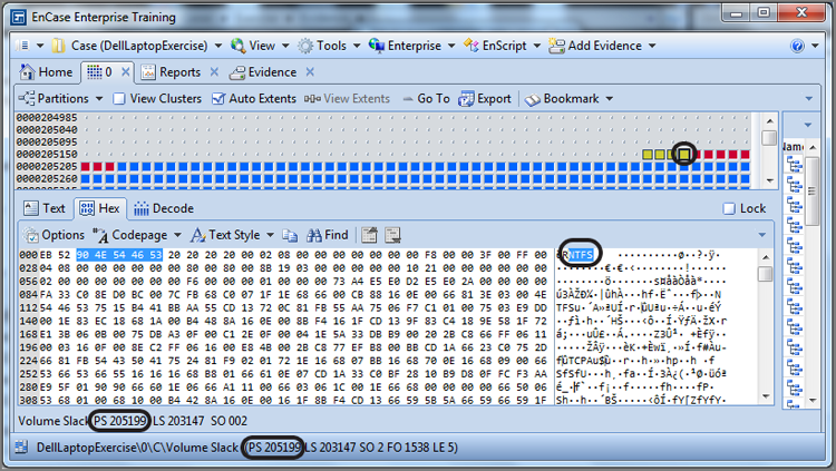
Figure 10-4: This partition starts at sector 2,052, which contains the VBR for an NTFS partition.
If a partition utility such as FDISK is used to remove a partition, the 16 bytes for that partition in the partition table are changed to zeros. Figure 10-5 shows a partition table after FDISK was used to remove all partitions. The partition itself, however, and all of its data are untouched by the process. It is similar to the process of deleting a file—only the pointers to the data are removed or altered; the data remains unchanged. With that in mind, it should be apparent that a partition can be easily recovered under these circumstances.
Figure 10-5: The partition table contains all zeros after FDISK was used to remove all partitions. There is no directory structure, and all squares in the Disk view indicate “no partition.”
To recover deleted partitions, you must locate the beginning of the partition by locating the VBR. Because VBRs have telltale signatures, they are relatively easy to locate. While looking for VBRs, you will encounter a few search hits that are not partitions. Each NTFS partition keeps a backup copy of the VBR in the last sector of that partition. Of course, knowing where a partition ends is also useful information. The recommended method of recovering partitions is to start with the partition found nearest to the beginning of the drive and work from that direction, restoring partitions as you go. When you do, you’ll find that many of your “hits” will be within allocated files or within the restored partition, as in the case of the backup VBR.
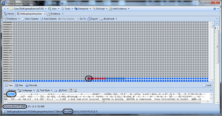
You know that the MBR is in the first sector of an MBR partitioned drive, which is sector 0. Because most drives currently have 63 sectors per track and the remainder of the first track is unused, you can expect sector 1 through sector 62 to be all zeros. Some tracking utilities write data in this space, but most of the time it will contain zeros. Sector 63 is the first sector of the second track and where you will usually find the beginning of the first partition for operating system drives before Vista. Starting with Vista, the VBR (the beginning of the NTFS partition) is normally installed at sector 2048 on a new installation of an operating system, as shown in Figure 10-6. While it’s not often encountered anymore, on older drives, where there were 39 sectors per track, look at sector 39 for the beginning of the first partition.
Figure 10-6: VBR or beginning of NTFS partition on a Windows 7 operating system drive (new installation)
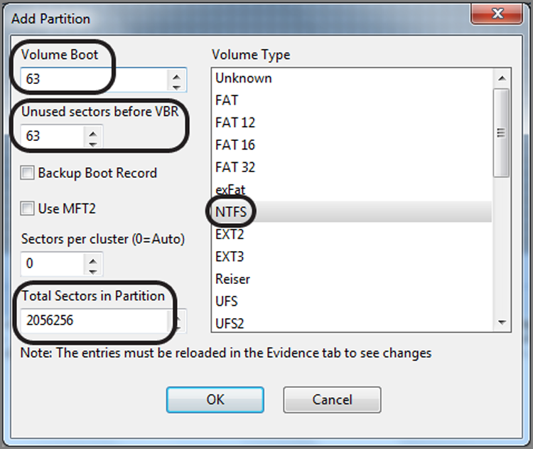
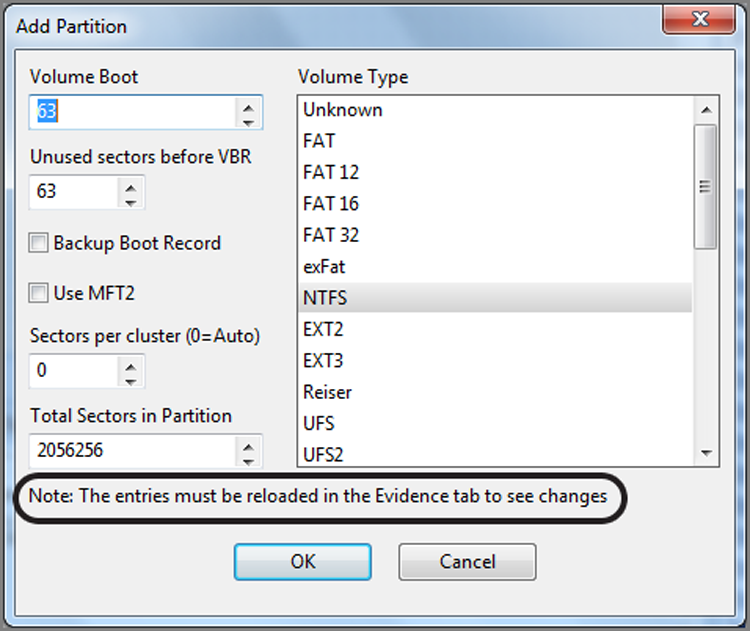
Most certainly you could have crafted a search term to locate this VBR, but because you know the common places to look, it is often quicker to go to those sectors (39, 63, 2048) first. The drive in this example is an XP operating system on a drive with 63 sectors per track and has had its partition removed, as you can recall from Figure 10-5. If you take a shortcut and go immediately to sector 63, you’ll see a VBR at that location. While in the Disk view, place your cursor on the sector containing the VBR (the beginning of the partition), which is sector 63 in our example. On the Disk view menu bar, under Partitions, choose Add Partition, as shown in Figure 10-7. You will see the Add Partition dialog box, as shown in Figure 10-8. EnCase will parse the data in the VBR and use that information to populate the fields in the dialog box, which will be used to correctly rebuild the partition. Click OK; EnCase will restore the partition. To view the restored partition, you must go back to the Table tab on the Evidence tab and reopen the evidence item, and the directory structure will then be visible in the Tree pane view.
Figure 10-7: Sector 63 is selected, and under the Partitions menu, Add Partition is chosen.
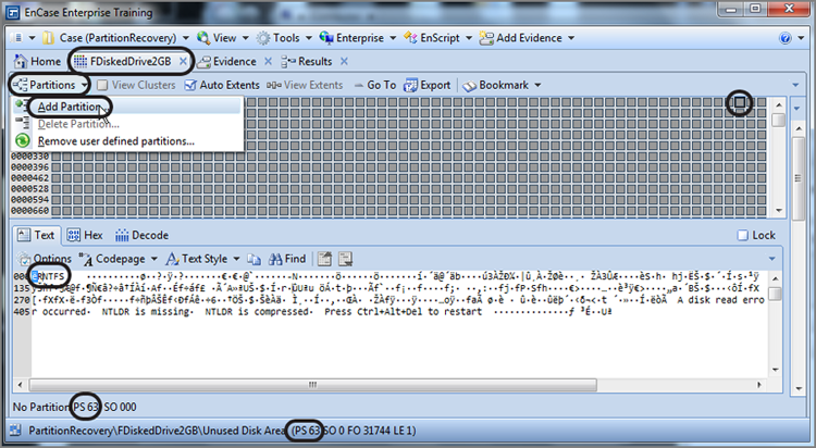
Figure 10-8: Add Partition dialog box—values therein are obtained when EnCase reads the data from the volume boot record
It is important to note that the evidence file is not changed by this process. Even after you have restored the partition, if you go back and check, you will find that the partition table still contains all zeros. EnCase restores the partition virtually with pointers contained within the case file. Figure 10-9 shows the correct directory structure after the partition was restored.
Figure 10-9: After the partition is recovered, the directory structure is restored to normal.
If you need to remove a partition, from the Disk view, go to the sector where you created the partition, and from the Partitions menu, choose Delete Partition. Alternatively, you could choose Remove User Defined Partitions, and any user-defined partition will be deleted.
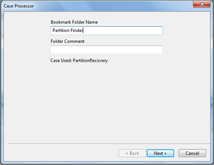
If you have more than one partition to restore or you have the potential for other than the run-of-the-mill Windows partition types to exist, it then becomes advantageous to search for partitions. You could create a series of search strings and search for them manually; however, EnCase has a well-designed EnScript to do that work for you. It is an option or module within the Case Processor EnScript. When you run the Case Processor EnScript, located on the application toolbar under EnScript, you will see a dialog box asking you for a Bookmark Folder Name, as shown in Figure 10-10.
Figure 10-10: In the first stage, you are prompted for a Bookmark Folder Name.
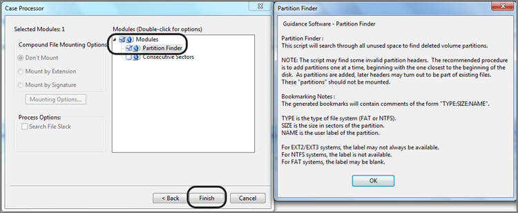
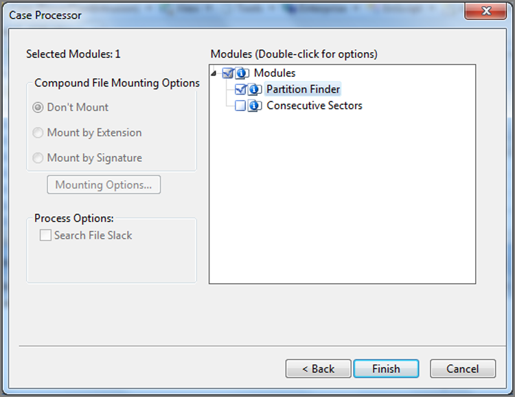
Once you enter a Bookmark Folder Name, choose Next and then select Partition Finder with a blue check mark, as shown in Figure 10-11. If you double-click Partition Finder, you’ll see a Help screen, explaining how the parser works and what to expect, which is also shown in Figure 10-11. Click Finish to run the EnScript, and when done, go to the Bookmarks tab and view the results under the folder, in this case Partition Finder.
Figure 10-11: The Partition Finder EnScript will locate partitions and note them in a bookmark.
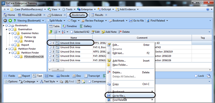
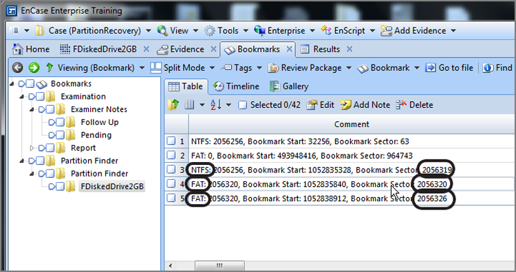
If you go to the Bookmarks tab after running the EnScript, you’ll typically find the partitions located by the EnScript along with, very often, some false positives. The bookmark will contain a comment for each hit that describes the partition parameters in the format Partition Type : Size in Sectors : Name (if available), along with Bookmark Start and Bookmark Sector. Figure 10-12 shows the results of running the Partition Finder. You will note that five hits were reported, and the Comment column shows the information about the partition. Note that the columns have been arranged in an optimal manner for this task.
· Name column: Contains name of area where search hit found
· Comment column: Contains partition information
Figure 10-12: The Bookmark view shows the results of the Partition Finder. Note the columns and their arrangement.
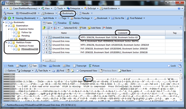
By arranging the columns as shown in Figure 10-12, you can see at a glance which bookmarks are most likely partitions and which are most likely not. Now it is time to logically examine the results. While in another view, I examined the device before I started this process and determined it contained 4,124,736 total sectors. The first bookmarked item starts at sector 63. Because the device has 63 sectors per track, sectors 0–62 (63 sectors) appear on the first track. Sector 63 marks the beginning of the second track and the normal location for the first partition. It makes sense, therefore, that this search hit is describing a valid partition. If you look at its size, which is 2,056,256 sectors, you find that it covers about half the drive.
If you examine the other search hit, located at sector 118,911, you see that it is contained within the recovered partition. You might therefore conclude that it is a false hit, such as a backup VBR, or data within a file. With that conclusion, you could dismiss it and move on—or you could consider one more possibility. Suppose there were, at one time, two partitions on this drive and the user removed them and partitioned the device in a different partition sizing layout. The first partition starting at sector 63 would have been overwritten immediately, but the partition starting somewhere out there in the middle of the drive might still exist and be recoverable. That said, in most cases, you’d want to investigate this possibility by restoring a partition in that location and reviewing the results.
In our example, we want to proceed by restoring the first partition found, which is located at physical sector 63. On the first search hit showing on the Bookmarks tab, right-click it and choose Go To File, as shown in Figure 10-13.
Figure 10-13: Right-click the search hit on the Bookmarks tab, and choose Go To File.
This will launch a separate tab within Bookmarks tab showing the containing file (in this case Unused Disk Area) with the cursor on the offset containing the search hit in the Text view, as shown in Figure 10-14.
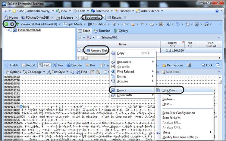
While in this view, from either the Table view or the Text view, right-click and choose Device > Disk View, as shown in Figure 10-15; you’ll be taken to the Disk view and directly to the sector containing the start of the partition, based on the selected search hit.
Figure 10-14: New tab under Bookmarks tab showing the Text view
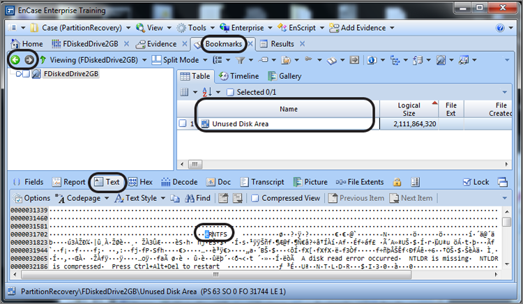
Figure 10-15: Right-click in Table view or Text view and choose Device > Disk View.
With sector 63 selected, as shown in Figure 10-16, go to the Partitions menu, as shown in Figure 10-17, and choose Add Partition. Accept the defaults, shown in the Add Partition menu, which are shown in Figure 10-18, and choose OK, which inserts the defined partition. As before, you need to reload the evidence entries on the Evidence tab to see the restored partition.
Figure 10-16: Disk view that lands on sector containing selected search hit, which is also the volume boot record where the partition is to be inserted
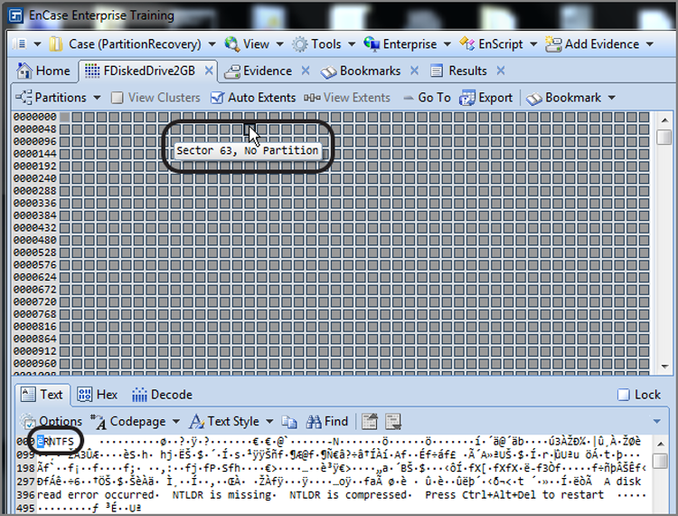
Figure 10-17: Partitions menu is accessed from Disk view
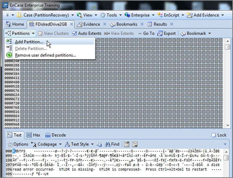
Figure 10-18: Add Partition dialog box
As previously mentioned, this partition occupies about half of the device, which means either that the rest of the device is unpartitioned or that another partition exists and needs to also be restored. If you go back to the Bookmarks tab and carefully review the other partition signature search hits, shown in Figure 10-19, you’ll note that the third search hit is the backup VBR existing in the last sector (2,056,319) of the partition we just restored. You’ll also note that the fourth search hit appears to be a valid FAT partition (VBR) starting in the first sector immediately after the partition we just inserted, which is sector 2,056,320. Further, there is a backup VBR in the seventh sector after this VBR, which is the earmark of a valid FAT32 partition. Thus, it seems clear that we have another partition to insert at sector 2,056,320 (the fourth search hit).
Figure 10-19: The fourth search hit is a VBR for a FAT32 partition that needs to be restored.
If we follow the same steps for restoring the first partition—right-clicking the fourth search hit, choosing Go To File, and then right-clicking in the Table view of the resulting screen and choosing Device > Disk View—we end up in the Disk view with our focus on the sector where we need to insert the FAT partition, which is sector 2,056,320 and shown in Figure 10-20. With our focus on that partition, simply choose Add Partition from the Partition menu, accept the defaults, and choose OK. Remember to reload the evidence item in the Evidence tab. Now both partitions should be available in the Tree pane, as shown in Figure 10-21.
Figure 10-20: Disk view with focus on sector 2,056,320, which is the VBR for a FAT32
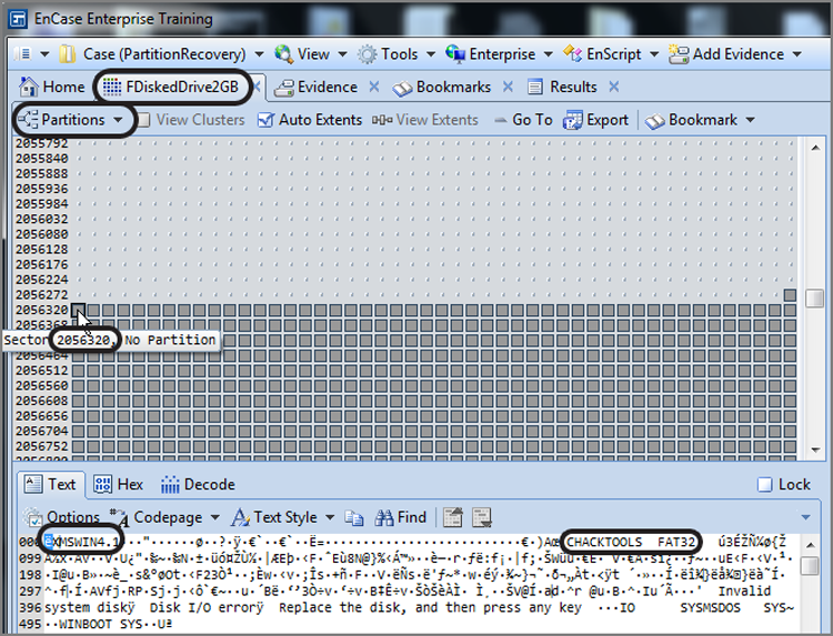
Figure 10-21: Tree view showing both restored partitions
As with most knowledge, it is enhanced by practical skills that make use of that knowledge. In Exercise 10.1, you recover a partition. You should do this exercise now while the concepts are fresh in your mind. You’ll understand it better and will retain the knowledge longer.
Exercise 10.1
Partition Recovery
In this exercise, you will examine a drive on which the partitions have been deleted using FDISK. You’ll locate and recover those partitions.
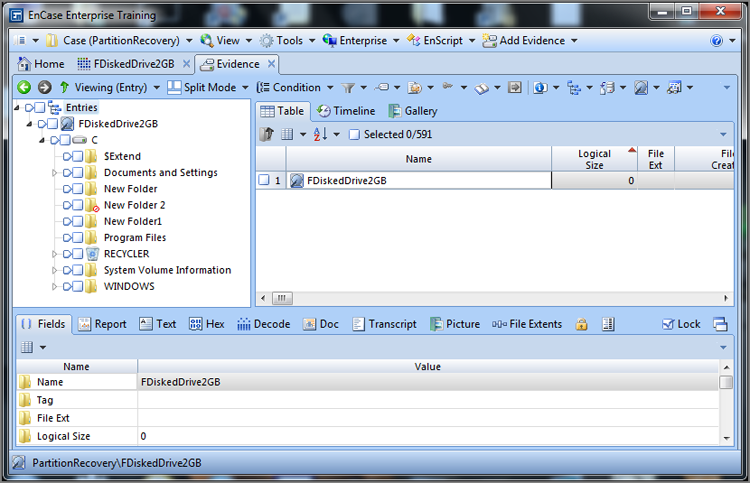
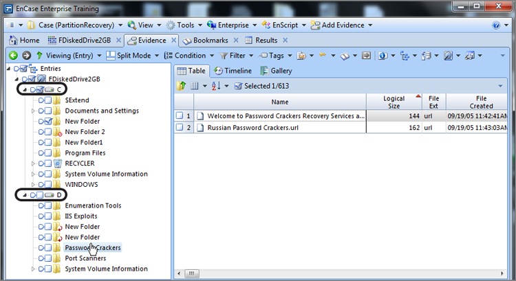
1. Create a new case, naming your case Partition Recovery. Locate an evidence file on the publisher’s website for this book, named Advanced\FDiskedDrive2GB.E01. Place it in an evidence folder along with those created by EnCase 7 for your newly created case.
2. With a new case created, from the Home tab, click Add Evidence and next choose Add Evidence File. Browse to the location where you placed the file FDiskedDrive2GB.E01. Once you have located it, select it, and click Open.
3. You will now be in the Evidence view with the one evidence item showing. Double-click this evidence item to have it parse and appear in the Entries view. When you do, you will immediately note that no partitions are present and that all data appears as Unused Disk Area. If you closely examine the first physical sector, you will see that it contains data but that the partition table area (byte offsets 446-509) contains all zeros, indicating that the partition table has been zeroed out and any defined partitions deleted.
4. From the Table view, right-click the device and choose Device > Disk View. Knowing that often the first partition can be found at sector 63, examine the contents of that sector, and you will note that it appears to contain the VBR for an NTFS partition. Let’s insert a partition at this point and examine the results.
5. From within the Disk view, with your cursor on sector 63, choose the Partitions menu and choose Add Partition. Accept the defaults and click OK.
6. Return to the Evidence tab and the Entries view. You will note that view at this point remains unchanged by the addition of the partition. This is expected as we must return to the Evidence tab Table view and force our evidence item to be reparsed. To do so, click the green left arrow to the left of the words Viewing (Entry). Next, simply double-click the evidence item; you will be returned to the Entries view, and your added partition will be fully viewable.
7. One might consider the work done at this point, but one should always account for all drive geometry because there could be yet another deleted partition. In fact, if you force the device to appear in the Table view and look at the Report view for that device in the View pane, you will note that the device contains 4,124,736 sectors and that the recovered partition accounts for only 2,056,319 sectors or about half of the total drive space.
8. There are essentially two approaches to handling this situation. You could use the Partition Finder contained within the EnCase Evidence Processor to locate partition signatures and work through the results, adding the partition when found. Alternatively, and often much more quickly, you could go to the end of the recovered partition and examine the sectors in the area for the presence of another partition. Let’s do the latter.
9. From the Disk view, right-click any sector and choose Go To. In the Go To window, type in 2,056,318 and click OK, which should take you to the last sector in the recovered partition. If you step over to the next sector (2,056,319), you will see the backup VBR for the recovered partition. Continuing to the next sector (2,056, 320), you will see what appears to be the VBR for a FAT32 partition. If this is a valid FAT32 partition, you would expect to see a backup VBR located six sectors from here at sector 2,056,326. When we examine this, we confirm the presence of the backup VBR and realize that we need to add a partition at the primary VBR located at sector 2,056,320. Place your cursor on that sector and, from the Partition menu, choose Add Partition. In the input block Unused Sectors Before VBR, change the value of 63 to 0, and click OK.
10. As before, return to the Evidence tab Table view and double-click the evidence item to force it to reparse. The result will be displayed on the Evidence tab Entries view, and both user-added partitions will now be visible. Be sure to save your work at this point!
Mounting Files
Many files are compound in nature. A compound file contains data that may be hierarchical, compressed, encrypted, or a combination of these methods. Its raw data is often illogical, difficult, or even impossible to view in its native state. EnCase can decode and mount these files so they are displayed in a logical or hierarchical format. In this manner, the examiner can see the data in the file in a more meaningful and logical format.
It is important to understand which files can be searched without mounting and which files can’t be searched until they are mounted. Also, it is important to understand that certain files are mounted as part of other processing.
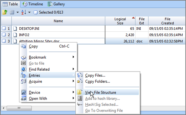
The process is the same for mounting any compound file. You simply right-click the file, under the Entries option select the View File Structure option, and then click OK in the resulting dialog box. Figure 10-22 shows the right-click menu with the option View File Structure selected.
Figure 10-22: To mount a compound file, right-click it and choose View File Structure under the Entries option.
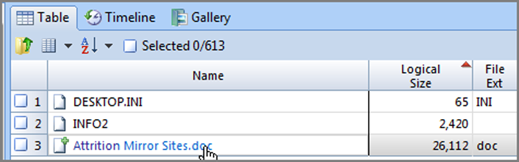
EnCase mounts the compound file, and the mounted file will be visible in blue to indicate that it is a hyperlinked object. If you hold your cursor over the hyperlink, the cursor will change to a hand, which is depicted in Figure 10-23. In past versions of EnCase, a mounted file was stored in RAM and consumed significant resources, especially when many large compound files were mounted. EnCase 7, by contrast, mounts compound files by creating logical evidence files for each mounted file and stores them in the EvidenceCache folder. This is a far more efficient method of mounting compound files and negates the need to dismount them. Currently, as of EnCase 7.04 there is no method by which to unmount or close a mounted file, but a future release may provide that option, even though it is not really necessary.
Figure 10-23: A mounted compound file is shown in blue indicating its hyperlinked status. The cursor changes to a hand when placed over a mounted compound file.
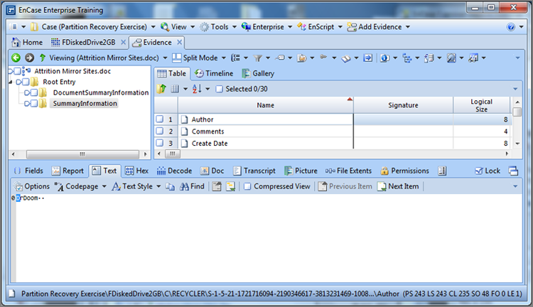
To view a mounted compound file, simply click the blue hyperlink, and the mounted file will launch in its own window within the Evidence tab, as shown in Figure 10-24. From this view, you can navigate its structure from within the Tree pane beginning at the special icon denoting the root of the mounted compound file, which is also shown in Figure 10-24. Any object within the mounted structure can be bookmarked and subsequently included in your final report.
Figure 10-24: Mounted files are viewable in their own separate window on the Evidence tab.
![]()
Often there are temp files that are compound files. Running a file signature analysis reveals these file as having an alias of * Compound Document File in the file signature column. These files are good candidates to mount and examine.
The list of files that can be mounted seems to grow with each release of EnCase. Table 10-1 describes the most common files that can be mounted within the EnCase environment. There is a brief description of the file and what data can be seen upon mounting.
Table 10-1: Listing of common compound files that can be mounted in EnCase
|
File |
Type |
Description |
|
.dbx extension |
Outlook Express email |
Mounting places emails in a hierarchical structure instead of viewing in a flat file. |
|
.mbx extension |
Outlook Express email (earlier versions) |
Mounting places emails in a hierarchical structure instead of viewing in a flat file. |
|
.doc/.docx extension |
Microsoft Word document |
Mounting places various objects in a folder structure so that you can view the document properties, including the data, document summary information, and so on. |
|
.xls/.xlsx extension |
Microsoft Excel spreadsheet |
Mounting places various objects in a folder structure so that you can view the various document properties such as the data, document summary information, and so on. |
|
.ppt/.pptx extension |
Microsoft PowerPoint document |
Mounting places various objects in a folder structure so you can view the various document properties such as the data, document summary information, and so on. |
|
.zip extension |
WinZip-compressed file |
Mounting decompresses the archives, presenting the individual files for examination. |
|
.pst extension |
Outlook email |
Mounting places emails in a hierarchical structure instead of viewing in a flat file. Outlook’s structure is very detailed. |
|
.MailDB extension |
MSN mail (has .dbx header and structure) |
Mounting places emails in a hierarchical structure instead of viewing in a flat file. |
|
.msi extension |
Microsoft Installer |
Mounting shows some of the properties of this installer package. |
|
Thumbs.db |
Hidden system file created when using Windows Explorer in the thumbnail view |
Mounted file shows thumbnails of images in folder on the last occasion the user viewed thumbnails. Can show thumbnail images of files that were deleted. It also shows that user saw images and was aware of contents, which is useful in cases where inappropriate or unlawful images are at issue. |
|
SYSTEM.DAT USER.DATSystem Security Software SAM Default NTUSER.DAT |
Registry files for Windows 9x and NT systems |
Mounting these files parses the specific registry hive and allows the examiner to navigate that branch of the registry in a hierarchical view. See the next section, “Registry.” |
|
.tar extension |
tar-compressed file |
Mounting decompresses the archives, presenting the individual files for examination. |
|
.rar extension |
rar-compressed file |
Mounting decompresses the archives, presenting the individual files for examination. |
|
.bzip2 |
bzip2-compressed file |
Mounting decompresses the archives, presenting the individual files for examination. |
|
.CLOOP |
CLOOP-compressed archive |
Mounting decompresses the archives, presenting the individual files for examination. |
|
.rzip extension |
rzip-compressed file |
Mounting decompresses the archives, presenting the individual files for examination. |
|
.gzip extension |
gzip-compressed file |
Mounting decompresses the archives, presenting the individual files for examination. |
|
.arc extension |
arc-compressed file |
Mounting decompresses the archives, presenting the individual files for examination. |
|
.cab extension |
Microsoft Installation Archive |
Mounting decompresses the archives, presenting the individual files for examination. |
|
.pfc extension |
AOL Personal File Cabinet |
Mounting makes available the content of the PFC. |
|
.nsf extension |
Lotus Notes data stores |
Mounting places emails in a hierarchical structure instead of viewing in a flat file. |
|
.edb extension |
Microsoft Exchange email database file |
Mounting places emails in a hierarchical structure instead of viewing in a flat file. |
|
.mbox extension |
Unix email |
Mounting places emails in a hierarchical structure instead of viewing in a flat file |
|
Cpio |
Macintosh PAX archive |
Mounting decompresses the archives, presenting the individual files for examination. |
|
.stf extension |
Archive file associated with ShrinkToFit |
Mounting decompresses the archives, presenting the individual files for examination. |
Some compound files can be searched without mounting them; others require mounting before they can be searched. For the most part, the determining factor is whether the data is compressed, encrypted, or both. For example, ZIP or TAR files are compressed, and a normal search using the active code page won’t find data within them. If you mount them, however, the compressed text is uncompressed during mounting, and they can then be searched.
An Outlook PST file, for example, stores its data using Outlook compressible encryption. Thus, it is compressed and encrypted. If you search this file using the active code page, don’t expect to find any meaningful data. If you mount this file, the data is uncompressed, decrypted, and displayed in a hierarchical structure. In this format, it can be easily searched.
When you search for email or Internet history, EnCase mounts the various files you have selected (choosing Outlook causes the PST file to be mounted, Outlook Express causes the DBX and MBX files to be mounted, and so on). Once you have them mounted, you can effectively search them.
Microsoft Office documents can be searched without mounting. Mounting Office doesn’t decrypt or uncompress data; it simply places data in a hierarchical format for organized or logical viewing.
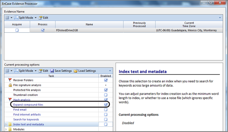
The EnCase Evidence Processor contains an option to mount certain compound files, as shown in Figure 10-25. Currently the feature supports the following archives: ZIP, GZIP, TAR, RAR, THUMBS.DB, CLOOP, and BZIP2.
Figure 10-25: EnCase Evidence Processor’s compound file mounting feature
File Signatures and Non-Windows Systems
If you’ll recall, Macintosh, Unix, Linux, and so forth, do not use file extensions for application binding. Although Macintosh is moving into that area, you can’t count on having file extensions in these environments. Thus, when using the File Mounter, you will want to search for compound files by both extension and signature if you are working on a non-Windows system. In fact, you may want to use it almost always because compound files created on other than Windows machines often find their way onto Windows systems from downloads, email attachments, and the like. Also, some browsers store Internet cache files in renamed files with no file extensions.
Thus, if you want to be thorough and find and mount all compound files, search by both file extension and file signature on both Windows and non-Windows systems.
Searching for Outlook PST Data in the Unallocated Clusters
Outlook leaves fragments of its data throughout the hard drive in slack space, in unallocated space, in the swap file, and in the hibernation file. This space can’t be mounted as a PST file, but it can be effectively searched for Outlook data.
1. The first step is to create a keyword to search. When you create the keyword, you need to select a Unicode search and uncheck the current active code page.
2. Next, go to the Code page tab. Go down the list of available code pages until you reach the Outlook Compressible Encryption code page, which is code 65003.
3. Place a check mark next to this code page, and then click OK to create your keyword.
4. Search your case using this keyword.
5. Go to the Results view and review your search hits in the View pane, using the Text tab. Any search hits that appear immediately in clear text are not ones that are in Outlook Compressible Encryption. To see those search hits, go to the Code Page menu and change into Outlook Compressible Encryption. Now your results will appear in gibberish, except for those in clear text, which are decoded from Outlook Compressible Encryption.
6. Bookmark any hits of import and then view the results in the Bookmark view. You will find that the code page used when the bookmark was created follows the bookmark, and you don’t need to make any further adjustments as in past versions of EnCase.
Registry
The Windows registry is a central repository or database of the configuration data for the operating system and most of its programs. Although the registry creates a convenient central location for this data, it also creates the potential for a single point of failure that can bring the system to a halt. Because of that vulnerability, the operating system uses safeguards to enable recovery to safe configurations through the use of “last known good configuration” and restore points in Windows XP/2003/Vista/2008/7.
![]()
To understand the registry as seen in EnCase, you need to understand the live registry as seen in Windows. As you go through this chapter, you will explore and in some cases make changes to your system registry. No discussion of registry changes would be complete without the customary warning: changing your system registry could harm your operating system. Consequently, if you aren’t comfortable with doing so, don’t. If you want to make changes, back up your registry first, or create a restore point before proceeding.
With the warnings behind us, let’s proceed. To be certain, the registry is a gold mine of forensic evidence. Since Microsoft discourages users, administrators included, from accessing or modifying the registry, it is doing its part in helping us preserve evidence, for which we are most grateful. As an examiner, you need to be very comfortable navigating within and working with the data in the registry. Comfort comes with knowledge, understanding, and experience, which are the precise goals of this section.
In the following sections, I’ll provide a background of the registry, including its history and its current structure. I’ll introduce you to the terminology associated with the registry, such as hives, keys, subkeys, and values.
Once I describe the terminology and structure, I’ll cover research techniques that will enable you to truly understand the internal workings of the registry. I’ll target an obscure and little-understood registry key for this research. When you are done with this chapter, you will join a relatively elite group of examiners who understand and properly interpret the function and values contained in this key. Its forensic usefulness will unfold before your eyes!
If you are going to testify about what a particular value in the registry means, you need to be able to demonstrate and explain those values. After completing this section, you should have the tools and techniques to do so.
Registry History
If you trace Windows back to its roots, its predecessor was MS-DOS. MS-DOS was a command-line interface whose configuration settings, by today’s standards, were anemic. MS-DOS received its configuration settings from two modest little files: config.sys and autoexec.bat. The config.sys file primarily loaded device drivers, and autoexec.bat was for setting environment variables, running programs, and the like.
The first Windows GUI was Microsoft Windows 3.0. This first version of Windows introduced INI files as containers for configuration information. These were flat text files with no hierarchical structure, and related configuration data was stored in sections. Text files made it difficult to store binary data, and the INI files were numerous and lacking in organization.
Windows 3.1 followed shortly after Windows 3.0, and with it came the rudiments of the system registry as a repository for system configuration settings. Windows 95 and NT 3.5 expanded the registry to the structure and interface that we recognize today in Windows 7, although it was a fraction of the size and complexity of today’s registry. The files in which the registry values are stored have gone from two with Windows 9x to six or more with Windows 2000/XP/2003/Vista/2008/7.
Registry Organization and Terminology
The Windows registry is stored in files called hives at a physical level. The interface for the user and applications takes on a logical scheme or format that resembles the directory structure used by Windows Explorer to store data in files and folders. Instead of using folders, the registry uses keys. Instead of using files, the registry uses values. If you think of it using that analogy, you are well along your way to understanding the hierarchy and terminology.
The user primarily views or modifies the registry with the registry editor tool. With Windows 2000, you had to choose between two registry editors (regedit.exe or regedt32.exe) depending on the task at hand. Either would allow you to view and navigate the registry, but each had capabilities and limitations that the other did not have, forcing a choice at times. Fortunately, Microsoft resolved that problem with the release of Windows XP/2003 and combined all features into one registry editor known simply as regedit.
Microsoft does not provide a shortcut to the registry editor in any known dialog box. In fact, Microsoft keeps the registry well below the radar screen, making only brief mention of the registry in the Windows help feature. At every stage Microsoft recommends against editing the registry, even to the point of recommending that administrators edit the registry as a last resort. That being said, you’ll find regedit.exe in the root of Windows, and you can usually access it from the Run command. To open the Run command, hold down the Windows key, and press R (for run). In the resulting window, type regedit, and press Enter. Figure 10-26 shows the Windows 7 registry editor when you open it. The left pane is known as the key pane, and the right pane is known as the value pane.
The Windows registry consists of five root-level keys, shown in Figure 10-26. Table 10-2 describes these root keys. Of those five root keys, only two are master keys, while the remaining three are derived keys that are linked to keys within the two master keys.
Figure 10-26: The Windows 7 registry editor
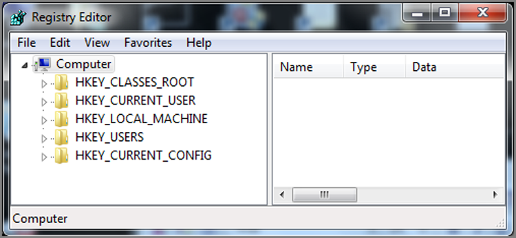
Table 10-2: Five root keys of the registry
|
Root key name |
Description |
|
HKEY_CLASSES_ROOT |
Used to associate file types with programs that open them and also used to register classes for Component Object Model (COM) objects. It is the largest of the root keys in terms of the registry space it occupies. This key is derived from a linked merger of two keys, which are HKLM\Software\Classes and HKCU\Software\Classes. This merger effectively blends default settings with per-user settings. |
|
HKEY_CURRENT_USER |
Used to configure the environment for the console user. It is a per-user setting (specific only to this user) and is derived from a link to HKU\SID, where the SID is the user’s security identifier. |
|
HKEY_CURRENT_CONFIG |
Used to establish the current hardware configuration profile. This key is derived from a link to HKLM\SYSTEM\CurrentControlSet\Hardware Profiles\Current. Current is derived from a link to HKLM\SYSTEM\CurrentControlSet\Hardware Profiles\####, where #### is a number that increments starting at 0000. HKLM\SYSTEM\CurrentControlSet, in turn, is a link to HKLM\SYSTEM\ControlSet###, where ### is a number that increments starting at 000. Which control set is current and used to create this key and subsequent link is determined by the value located in HKLM\SYSTEM\Select\Current. |
|
HKEY_LOCAL_MACHINE |
Used to establish the per-computer settings. Settings found in this key apply to the machine and all of its users, covering all facets of the computer’s function. This key is a master key and is not, therefore, derived from any link as are the previous three keys. |
|
HKEY_USERS |
Used for environment settings for the console user as well as other users who have logged onto the system. There will be at least three subkeys—.DEFAULT, SID, and SID_Classes, where the SID is that of the console user. You may also find SIDs S-1-5-18, S-1-5-19, and S-1-5-20, which are for the LocalSystem, LocalService, and NetworkService accounts, respectively. Any other SIDs found here will belong to other users who have logged on to the machine. This key is a master key and is not, therefore, derived from any link. |
At a physical level, each of the logical master keys has its source data stored in a file that is called a hive. In each of the two master keys (HKLM and HKU), there are subkeys named for each of the hive files. Table 10-3 shows the hive keys and the associated hive files from which they originate. These hive files are located in the folder %SYSTEMROOT%\System32\config, except for the new hive key that was introduced in Vista, which is the BCD, or Boot Configuration Data, hive. This hive file is located in the first partition, which is a hidden system partition. This file replaces the legacy boot.ini file. This file previously existed as a text file and was an easy target for malware. Part of the rationale for placing the boot data in the registry hive file was to make it more difficult for malware to utilize for start-up purposes. While it remains to be seen whether that rationale was valid, clearly the registry hive file format allows binary data storage and considerable extensibility for boot configuration data storage.
Table 10-3: HKLM hive keys and their corresponding hive files
|
Hive key |
Hive file |
|
HKLM\BDC00000000 |
\Boot\BCD (located on first partition!) |
|
HKLM\SAM |
%SYSTEMROOT%\System32\config\SAM |
|
HKLM\SECURITY |
%SYSTEMROOT%\System32\config\SECURITY |
|
HKLM\SOFTWARE |
%SYSTEMROOT%\System32\config\software |
|
HKLM\SYSTEM |
%SYSTEMROOT%\System32\config\system |
If you look at the live registry under the master key HKLM, you see the five hive keys listed in Table 10-3, plus you will see one more that is named HARDWARE. Interestingly, HARDWARE is a dynamic key with no source hive file at the physical level. It is created as a dynamic key in RAM when Windows boots. When the system shuts down, the data in this key is gone.
Thus far, we’ve covered the hive keys and files located in HKLM. The master key HKU has its share of hive files as well. In fact, each subkey under HKU is a hive key with a corresponding hive file. The hive files for HKU are found in several locations. Table 10-4 shows the various hive keys in HKU and their source hive files. When SID is referenced, it is the SID of the console user or other past logged-on user. When UserName is referenced, it is the username that corresponds to the SID.
Table 10-4: HKU hive keys and their corresponding hive files
|
Hive key |
Hive file |
|
HKU\.DEFAULT |
%SYSTEMROOT%\System32\config\default |
|
HKU\S-1-5-19 |
Documents and Settings\LocalService\NTUSER.DAT |
|
HKU\S-1-5-19_Classes |
Documents and Settings\LocalService\Local Settings\Application Data\Microsoft\Windows\UsrClass.dat |
|
HKU\S-1-5-20 |
Documents and Settings\NetworkService\NTUSER.DAT |
|
HKU\S-1-5-20_Classes |
Documents and Settings\NetworkService\Local Settings\Application Data\Microsoft\Windows\UsrClass.dat |
|
HKU\SID |
Documents and Settings\UserName\NTUSER.DAT |
|
HKU\SID_Classes |
Documents and Settings\UserName\Local Settings\Application Data\Microsoft\Windows\UsrClass.dat |
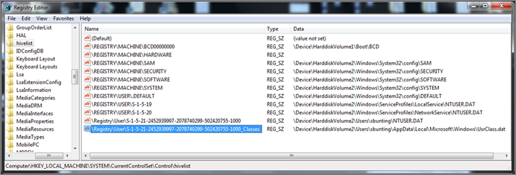
When the system loads these hives into the registry, there is one key that lists or maps the loaded hive files with their corresponding registry hive keys. This key is an excellent one to visit because it shows the relationships between hive files and hive keys that are loaded on the system (see Figure 10-27). You can find this key at HKEY_LOCAL_MACHINE\SYSTEM\CurrentControlSet\Control\hivelist but only in the live registry. When the system is shut down, none of the hives is loaded.
Figure 10-27: The key “hive list” shows currently loaded hive files and their mapping to registry hive keys.
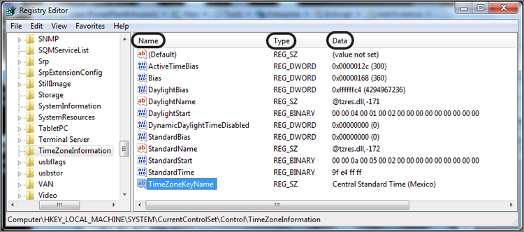
As I mentioned earlier, the registry keys are displayed in the left, or key, pane of the registry editor. It is from this pane that you can navigate among the various registry keys. The right, or value, pane is the pane in which you view or access the registry values. A value has three components: its name, its data type, and its data. Figure 10-28 shows the registry editor in which a series of values is shown in the right, or value, pane. In the value pane there is a column for each of the three value attributes (Name, Type, and Data).
Figure 10-28: Registry editor showing registry values in the right, or value, pane
All values have names; there can’t be a null name. A value’s name is analogous to a file’s name. A value name can be up to 512 ANSI characters in length (256 Unicode characters), except for the special characters: question mark (?), backslash (\), and asterisk (*). Furthermore, Windows reserves all value names that begin with a period (.). Just as no folder can contain two files with the same name, no key can contain two values with the same name.
Each value contains data of a specified data type. That type is specified by a number, which is interpreted by the registry API so that the user sees the data type in plain text. Table 10-5 shows each of the data types, their corresponding number, and a brief description of what the data type means. When you see a registry value in EnCase versions older than version 5, only the data type number will be shown, not the plain-text version rendered by the registry API. EnCase 5 and 6 interpret the numeric value and return the plain-text data type, as shown in Table 10-5. In all versions, the data type appears in the file type column. With EnCase 7, the file type column does not appear, and there is no information provided regarding the value data type.
Table 10-5: Listing of registry value data types
|
Data type |
Number |
Description |
|
REG_NONE |
0 |
Data type is not defined. |
|
REG_SZ |
1 |
Fixed-length text string expressed in user-friendly format, often used to describe components. |
|
REG_EXPAND_SZ |
2 |
Variable or expandable length data string. |
|
REG_BINARY |
3 |
Binary data, displayed in editor as hex. |
|
REG_DWORD |
4 |
32-bit double word value—the most common data type found in the registry. |
|
REG_DWORD_LITTLE_ENDIAN |
4 |
32-bit double word value with bytes in reverse order. Because Intel already stores data in this format, this term is synonymous with REG_DWORD, and they have the same numeric value. |
|
REG_DWORD_BIG_ENDIAN |
5 |
32-bit double word value with bytes in normal order, with the highest bit appearing first. |
|
REG_LINK |
6 |
An internal-use-only data type for Unicode symbolic link. |
|
REG_MULTI_SZ |
7 |
Multiple-string field in which each string is separated by a null (00h) and with two nulls (00 00) marking the end of the list of strings. |
|
REG_RESOURCE_LIST |
8 |
Listing of resource lists for devices or device drivers (REG_FULL_RESOURCE_DESCRIPTOR). You can view but not edit these lists. |
Using EnCase to Mount and View the Registry
I’ve now covered the basics of the live registry as seen by the user in a registry editor. It is the logical interface by which the registry hive files are addressed, viewed, and edited. The live registry, as thus far depicted, and the registry as seen in EnCase will have noticeable differences.
When you view the registry in EnCase, you are looking at only the hive files, and the view will differ from a live registry view in many ways. For example, you will not see the HARDWARE key that exists in the live registry under HKLM. This key is a dynamic key, created at boot, and exists only in RAM while the system is loaded and running. There is no hive file for this dynamic key.
You have seen that certain keys exist only virtually as links to keys on the master keys. You should not expect to see the virtual keys, but you can certainly view their data by going to the key to which they are linked. For example, don’t expect to see HKEY_CURRENT_USER in the EnCase registry. However, you know that this key is derived from the SID key under HKEY_USERS and that the SID key is actually a hive key whose source file is NTUSER.DAT, which is located in the root of the SID user’s folder (root user folder). By mounting and viewing a particular user’s NTUSER.DAT, you are looking at what was their HKEY_CURRENT_USER key and its content (user environment/profile) when they were last logged on.
In the previous section, “Mounting Files,” I described the registry files as being mountable files within EnCase. As with any other mountable file, to mount a registry hive file, you need only to right-click one of the hive files and choose to view its file structure from the Entries option.
![]()
If you look at the five hive files (SAM, SECURITY, SOFTWARE, SYSTEM, and DEFAULT) located in the %SystemRoot%\system32\config folder, you will note that they have counterparts by the same names located in the %SystemRoot%\repair folder. The ones in the repair folder are basic configurations for repair purposes if things go wrong. Here you want the active registry hive files in the config folder. Don’t confuse the two!
To mount any of the hive files, simply right-click the desired file and choose to view its file structure from the Entries option. Because some of these files are very large and complex, mounting them may take some time, but it’s usually less than a minute.
When the file mounts, you can navigate through the various keys as you would any hierarchical file structure. When a value is displayed in the Table view pane, you will see its name in the Name column and its data in the View pane in either the Text or Hex view.
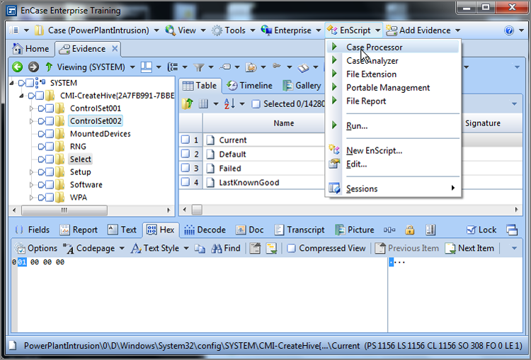
Figure 10-29 shows the system hive file mounted. The Select key contains four values. Although the others are important, you want to know which control set is current, and the value named Current contains the data that makes that determination. In this case, the data for the value named Current is a Dword data type and the data reads 01 00 00 00. This value translates to 1, and the current control set is 1. Forensically, we look to the values contained in ControlSet001 to be those of the CurrentControlSet.
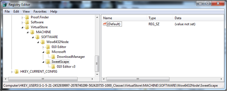
With Vista, registry virtualization was born, by which applications that do not follow the rules (principle of least privilege) and attempt to write to read-only areas of the registry (HKLM, for example) have their writes redirected to a special area dedicated for this purpose. The application is unaware that its data is stored in a new location as the calls are redirected to the virtualized area, and everyone is happy. For the examiner, however, the virtualized registry key is yet another area to examine so as to conduct a complete examination. This key is located at HKU\(User’s SID)_Classes\VirtualStore and is shown in Figure 10-30.
Figure 10-29: The system hive file is mounted. The Select key contains a value named Current whose data determines the CurrentControlSet.
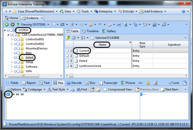
Figure 10-30: Location of VirtualStore and data located therein
Registry Hive Files in the Restore Points
Starting with Windows ME/XP, Windows creates restore points every 24 hours and retains them for up to 90 days, hard drive space permitting. Additionally, restore points are created before Windows updates, when software is installed, when an unsigned drive is installed, and when a user decides to restore to another restore point. They are also turned on by default, so you should usually expect to see them unless they have been disabled by the user or the hard drive is nearing its capacity.
Restore points are stored in the root-level folder \System Volume Information\-restore{GUID}\RP##, where ## are sequential numbers as restore points are created. Although the date the restore point was created is stored in the last eight bytes of the rp.log file, the file creation time for the RP## folder itself is also evidence of the restore point’s creation time.
As part of the restore point data gathering, Windows makes copies of the registry files and places them in the Snapshot folder, renaming them in the process. The Snapshot folder appears under each of the RP## folders. Thus, if you look in the Snapshot folders, you’ll see, among other data, renamed registry files. Table 10-6 shows the names of the more forensically significant registry hive files and their new filenames as stored in the restore points. Even though they’ve been renamed, you need only right-click them and choose View File Structure, and then they will be mounted.
With the advent of Windows Vista, restore points became much more sophisticated with the implementation of the Volume Shadow Service (VSS). Instead of just capturing snapshots of critical operating system and program files and settings, VSS contains snapshots of all data from a volume that has changed and does so from a block perspective, with each block being a 16 KB unit. Extracting data from the VSS copies is a somewhat onerous process but can be done. The result is a gold mine of forensic data, often containing copies of files long ago deleted and forgotten.
The ability to go back and view registry data at various points in time is a tremendous investigative tool with endless forensic possibilities. You can examine for changed settings before and after intrusions, old search histories, old most recently used (MRU) lists, and so on. Steve Anson and I teamed up to write the book Mastering Windows Network Forensics and Investigation, in which restore points are covered extensively. Recently Ryan Johnson and Scott Pearson joined the authors’ team and completed the second edition, updating the material significantly. The books are available here:
www.wiley.com/WileyCDA/WileyTitle/productCd-0470097620.html
www.wiley.com/WileyCDA/WileyTitle/productCd-1118163826.html
Table 10-6: Mapping of hive filenames to their restore point filenames
|
Original hive filenames |
Restore point filenames |
|
SAM |
_REGISTRY_MACHINE_SAM |
|
SECURITY |
_REGISTRY_MACHINE_SECURITY |
|
SOFTWARE |
_REGISTRY_MACHINE_SOFTWARE |
|
SYSTEM |
_REGISTRY_MACHINE_SYSTEM |
|
NTUSER.DAT |
_REGISTRY_USER_NTUSER_SID* |
* SID is the security identifier for the individual user. To locate a particular user’s NTUSER.DAT file, you need to know a SID number for the user in question.
Registry Research Techniques
You should, by now, have a good understanding of the registry and how it is logically organized. You should be familiar with the registry editor and navigating the registry keys. You should be able to determine a value’s name, data type, and data. You should also grasp the differences between the live registry in Windows and the offline registry as viewed in EnCase.
There will be times when you will want to know where a particular setting is located in the registry. Rather than ask and be forced to accept the word of a third party, wouldn’t it be better to research the issue and be able to testify in court, first hand, that you’ve tested and validated the result? Most certainly it would. In this manner, you can speak more authoritatively and confidently about your findings.
To conduct research into the live registry, there is no better tool than the free tools from Microsoft designed specifically for this purpose. Originally they were all separate tools (regmon, filemon, and so on), but they have now been rolled into one tool set named Process Monitor, available at http://technet.microsoft.com/en-us/sysinternals/bb896645.
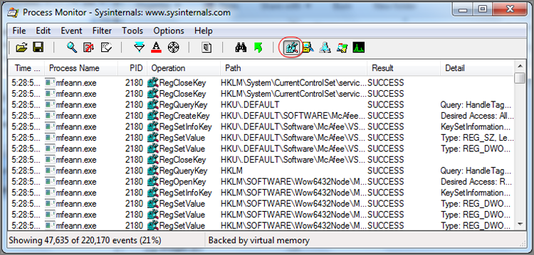
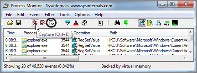
Once you’ve downloaded the tool, you need only run it because it requires no installation, making it also convenient to run from a thumb drive at times. By default, at launch, you are monitoring almost everything, and the result is simply too much data. To begin with, turn off File System, Network, and Process activity by clicking their icon buttons on the toolbar, as shown in Figure 10-31. This will leave only Registry Monitoring active.
Figure 10-31: Only registry-monitoring activity is enabled
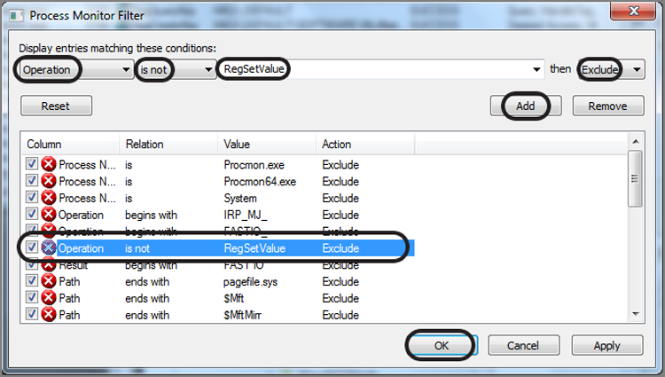
Next, you’ll want to filter for successful writes to the registry; otherwise, you are seeing reads and much else, which again results in too much data. To apply this filter, click Filter on the toolbar and choose Filter again. In the resulting menu, set the filter for Operation Is Not RegSetValue and then set Exclude. With those settings in place, click Add to place the filter in the list, as shown in Figure 10-32. When you click OK, the filter is applied.
Figure 10-32: Filter is set to exclude anything except operations that set registry values.
You are almost ready to go to work. The next thing you’ll want to do is to familiarize yourself with the button that toggles capture on and off, as well as the button to clear out data. Figure 10-33 shows the Capture button under the cursor. Two buttons to the right you will find the Clear button. Toggle off Data Capture and clear out any existing data. You are now set to investigate the registry.
Figure 10-33: The button to toggle data capture on and off is under the cursor. The Clear button is circled.
Let’s suppose we want to know which registry setting indicates whether Remote Desktop is enabled. If Remote Desktop is enabled, naturally this adds a new dimension to any case because the computer can be accessed remotely. Therefore, this should be a setting that we usually inspect on a routine basis. We must, however, first know where it is. Let’s allow Process Monitor to give us the answer.
Leave Process Monitor off for now. You want to capture data only for the brief instant that you apply a setting to minimize data and to zoom in on your finding.
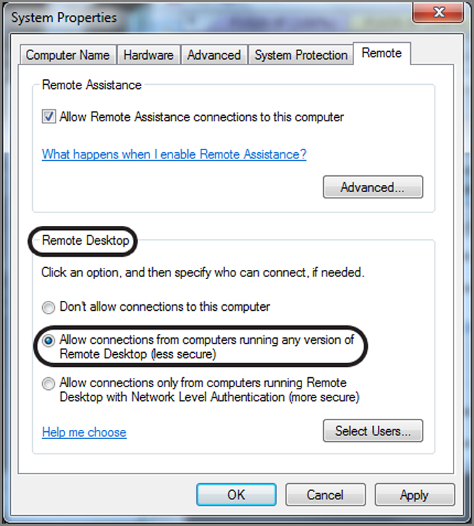
To enable or disable Remote Desktop, right-click Computer and click Properties. On the screen that follows, you will see Remote Settings on the left side of the screen. Click Remote Settings, which will open a System Properties menu that is opened to the Remote tab. In the bottom half of this menu are three settings pertaining to Remote Desktop. We’ll go forward with the presumption that the first option is enabled, which is to not allow remote connections to this computer. Click the middle button, which enables Remote Desktop from any version, as shown in Figure 10-34. Do not click OK or Apply just yet!
Figure 10-34: System Properties dialog box open to Remote tab from which Remote Desktop is enabled or disabled
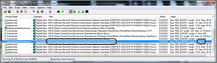
The next step is to get your Process Monitor window and your System Properties menu side by side and visible at the same time. When ready, you toggle on Data Capture, click Apply to apply the Remote Desktop settings, and immediately thereafter turn off the data capture. You should then see, among other data, the entry in the registry that enables Remote Desktop. As you can see in Figure 10-35, the registry key HKLM\System\CurrentControlSet\Control\Terminal Server\fDenyTSConnections will be set to zero when Remote Desktop is enabled. The default setting, 1, denies connections.
Figure 10-35: Process Monitor used to capture registry setting for enabling Remote Desktop
You can easily see how useful this tool can be in your examinations. Whenever you have a question about a setting, you can verify it on the spot in most cases. In the previous example, you could repeatedly toggle the feature on and off, capturing data each time. You could even tweak the registry directly to establish that it works. For those times when you encounter malware and have to test its impact and behavior on a test system or, better yet, a virtual machine, running this tool from a thumb drive can allow you to see all system activity that occurs. It is an incredibly useful tool in the advanced examiner’s toolbox.
EnScript and Filters
EnScript is a proprietary programming language and application programming interface (API) that exists within the EnCase program environment, which means EnCase must be running to run EnScripts. EnScript adheres to the ANSI C++ and Java standards for expression evaluation and operator meanings, making for an easy transition for those accustomed to programming in those languages. Even though EnScript adheres to those standards, only a small subset of C++ features is incorporated. In short, EnScript uses C++ operators and general syntax but uses different classes and functions.
EnScripts are scripts or small pieces of code that automate various forensic processing tasks. Examiners can use the EnScripts provided by Guidance Software, Inc., or they can create their own or share them with other examiners. For those interested in creating their own EnScripts, some programming background, particularly in object-oriented programming (OOP), is most helpful. Guidance Software offers a four-day class in EnScript programming for those seeking training in this area.
With EnCase 7, EnScripts are now conveniently accessed from their own drop-down menu on the application toolbar. Upon opening the drop-down menu, as shown in Figure 10-36, you have the option of accessing and running any of the five most recent EnScripts. Additionally, by selecting Run, you can browse to and run any EnScript. Finally, you can create a new EnScript or edit an existing one.
Figure 10-36: EnScript menu accessible from application toolbar
Running EnScripts
Running an EnScript, as you have seen, is as simple as double-clicking the EnScript name in the recent list or navigating to it under Run and launching it. As you have also seen, many EnScripts have several modules, and modules may have additional options. Many of you are probably familiar with the Case Processor from past versions of EnCase. In Figure 10-36, you may have noted the Case Processor. You will find that with EnCase 7, nearly all of the functions that used to be in the Case Processor are now included in the various modules found in the EnCase Evidence Processor. Currently, the Case Processor has two EnScript modules available, which are Partition Finder and Consecutive Sectors, as shown in Figure 10-37.
Figure 10-37: Case Processor features have moved to the EnCase Evidence Processor, leaving behind Partition Finder and Consecutive Sectors
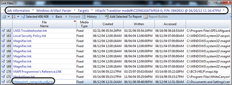
New to EnCase 7 is the Case Analyzer EnScript, which is a very powerful and easy-to-overlook set of analysis and summarization tools. This tool takes in and processes considerable case data from various sources and brings it together in a summary screen that you can drill down into and report upon at various levels of granularity. Figure 10-38 shows the Job Summary menu from which to start the drill-down process. Figure 10-39 shows having drilled down into the Windows Artifact Parser for the Hitachi Travelstar device and having chosen Link Files from among other options. The link file list can be sorted by any column, reports can be generated from selected items, or more information can be derived by clicking any particular link file. The information and reports available from this tool are vast and should offer something for nearly any case under examination. The best way to see what this tool can do is to simply explore and experiment.
Figure 10-38: Case Analyzer EnScript Job Summary report
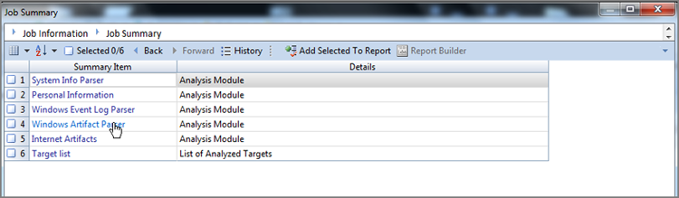
Figure 10-39: Results of link file analysis report—note the hyperlinked path bar that is circled
EnScripts are constantly undergoing improvements and additions. You should take the time to try them all on small test sets of data, so you understand how they work and how they can help you process more evidence in less time.
Filters and Conditions
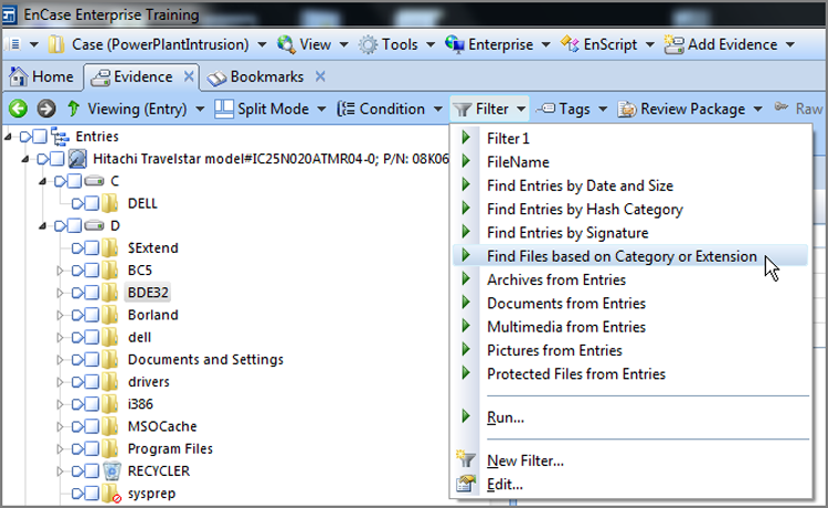
Filters are specialized EnScripts that allow you to filter your case based on a set of parameters. For example, you could filter for all files with the .xls extensions to view only spreadsheets. Several filters are included in EnCase when you install it. Filters are available, quite appropriately, from the Evidence tab toolbar between the Condition and Tags menus, as shown in Figure 10-40. Filters, like EnScripts, need only to be double-clicked to launch. There are often options after launch from which the user can apply added filter criteria.
Figure 10-40: Filter menu on Evidence tab toolbar
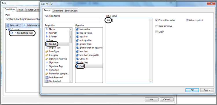
If you want to create a filter, you’ll have to do so using code. Conditions are much easier to create because they allow you to create filters using preset parameters available through dialog box choices. Conditions are available also from the Evidence tab toolbar. You can build powerful and useful conditions in addition to the ones that have been provided. Probably the easiest way to get started creating new conditions is to edit a condition (right-click and choose Edit) that approximates what you are trying to create. Figure 10-41 shows a condition in the Edit mode. Once you visit the various filter conditions in the Edit mode, the road map becomes very clear for creating your own conditions.
Figure 10-41: Condition in the Edit mode
When you run a filter or condition, the results, or found set, are returned in a Results tab and window. For EnCase veterans, this is a significant change in behavior but is clearly one for the better once you get beyond the change. You can do anything that you need to do to the found set on the Results tab. You can send multiple filters or queries to the Results tab, and from there, you can combine them and apply AND or OR logic to the combinations.
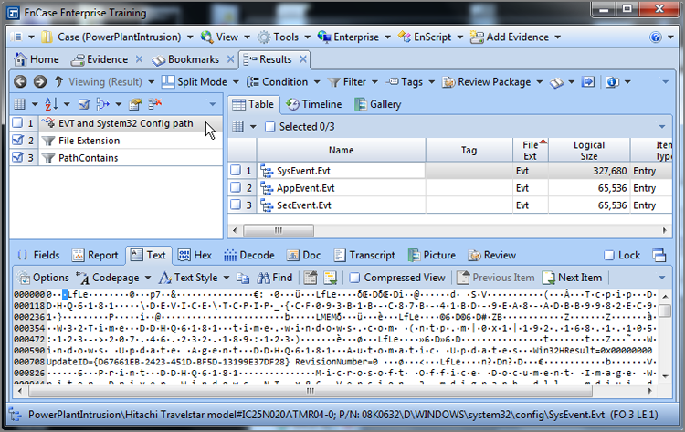
You combine them by selecting them and then choosing the logic to apply, as shown in Figure 10-42. Each combination is required to have a name, for which you will be prompted. By having this feature, you can save varying sets of combined filters and conditions. Figure 10-43 shows the end result. In this case, I created a condition to find all files in the case with .evt extensions and another condition to find all files with System32\config in their path. By combining them, I find only the .evt extensions in the previous path.
Figure 10-42: Combining two conditions with AND logic
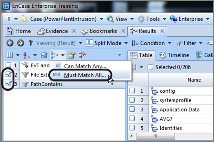
Figure 10-43: The combination is “named,” and the result of combining two conditions is shown.
For those seeking more information on the syntax for EnScripts or filters, visit the Guidance Software website at www.guidancesoftware.com, and go to the EnScript Language Reference section. Also, the various EnScript classes and functions are available from the EnScript editor interface that launches when you choose to create or edit an EnScript. There is also a separate and extensive EnScript help file that is included during the installation of EnCase.
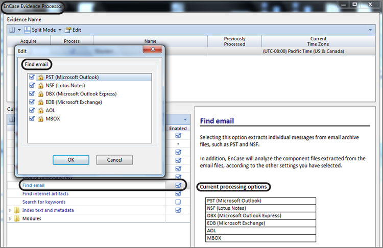
You probably recall from our discussions regarding the EnCase Evidence Processor (EEP) that it processes email as one of it feature sets. In this section, I’ll first review the EEP email-processing options. Next, I’ll cover how to examine the results of the email processor and bookmark those results into your report. The EnCase Evidence Processor has a Find Email module that will currently process the following email types:
· Outlook (PST)
· Outlook Express (DBX/MBX)
· AOL
· MBOX (a common flat file format)
· Lotus Notes (NSF data stores)
· Microsoft Exchange Email Server (EDB files)
To run the Find Email module, simply launch EEP, check the Find Email feature, and choose which email types you want to find, as shown in Figure 10-44.
Figure 10-44: Find Email feature in EnCase Evidence Processor
The results of the email finder are sent to the Records tab, which will be our work area for viewing them in a logical format. The email messages will displayed in a typical email format with headers such as From, To, Subject, Created Date, Sent Date, Received Date, Header, and Attachments; this information exists within any given email database.
You will notice the absence of any web mail options in the Find Email feature. Web mail has become increasingly more secure with time, and finding entire HTML web pages containing email is largely a thing of the past. Nevertheless, some web mail or fragments thereof can still be recovered, as can some important web mail that is residual from long ago in some cases. As part of a thorough examination, we always must look. To search for webmail, use the File Carver in the EEP, and in the bottom section, choose Carve HTML Files; under that option, also choose Carve Webmail Files.
There are some really good third-party tools available that have sought to fill a void by specializing in recovering Internet artifacts from the vast array of web-related communications services. Internet Evidence Finder from JAD Software is a very powerful tool that I highly recommend to expand your ability to recover these types of Internet communications. To the extent that Gmail fragments exist, it recovers more than any other tool with which I’ve worked.
With past versions of EnCase, you could use the View File Structure feature to both mount a compound email file, such as a PST, OST, and so forth, and populate the Records tab. With EnCase 7, using the View File Structure feature will mount a PST/OST and launch it in a separate tab within the Evidence tab, but it will not populate the Records tab. Unless you have a reason to do otherwise, I recommend processing email stores with the EEP. If you have to quickly review an email store, quickly mounting it with the View File Structure feature will certainly work for you in a pinch.
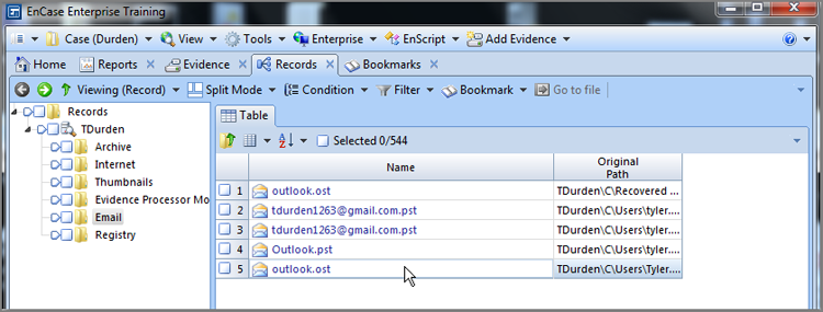
Once the EEP completes with the Find Email feature enabled, you can see the results on the Records tab. In the Tree pane, you will see, among other record folders, an email record folder. When you select it, the Table view will populate with the email stores found and parsed, as shown in Figure 10-45. The various email stores will appear in blue as hyperlinked. To view any one of them, merely click it for it to open in its own view within the Records tab.
Figure 10-45: Records tab containing, among other things, the results of the email finder
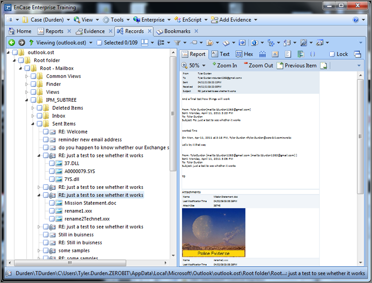
When you click an email store, a separate view or window will launch within the Records tab containing the parsed results for that particular email store. The Tree view will display a hierarchical view of the mail store, showing the various folders or mailboxes. Within them will be the emails themselves. The email will display in the Table view on the Report tab much as the user saw it, complete with attachments in view if viewable, as shown in Figure 10-46.
Figure 10-46: Email tree structure in Tree pane with individual email and attachments viewed in Table pane
You may easily right-click and bookmark any email from the Table view. As with other EnCase views, you may select multiple emails and bookmark them. Once bookmarked and placed in a destination folder, the bookmarked emails are viewable from the Bookmark view and subsequently viewable in your report.
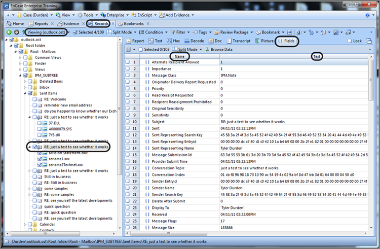
In the Table pane, you can select the field table, which will in turn display more than 100 fields (103 fields with version 7.03), as shown in Figure 10-47. Each field provides data for a specific property of each email, with some fields having null values when no data exists for that field.
Figure 10-47: Field tab displaying more than 100 fields with each containing data pertaining to a specific property for that email
In Exercise 10.2, you’ll get to work with the email finder in the EnCase Evidence Processor. You should take the time now to enhance your learning experience by doing this exercise.
Exercise 10.2
Conducting Email Examinations
In this exercise, you will examine email artifacts located using the Find Email feature of EnCase Evidence Processor.
1. Create a new case and name it Email Examination. Locate an evidence file on the publisher’s website for this book that is named Advanced\DrDoomRootUserFolder_CD001.E01. Place it in the evidence folder for your newly created case.
2. From the Home page, select Add Evidence > Add Evidence File. Browse to the location of the above evidence file and open it. From the Evidence tab Table view, check that the evidence file passed the file integrity test.
3. Launch the EnCase Evidence Processor, select the evidence item, and at the very least select the Find Email option, choosing DBX minimally as an email type for the search. If you’d care to explore other features, feel free to check them. It is a small evidence file and everything will process quickly.
4. When the EEP completes, double-click the evidence item to cause it to parse and display in the Entries view of the Evidence tab. From the View menu, open the Records view. From the Records view, click Email.
5. With email selected in the Tree pane, click the first inbox you see in the Table pane, which will open the inbox in a separate view. From the Tree pane, locate an email with a subject of “1st target.” Force it to display in the Table pane, using the Report tab.
6. From the Table pane Report tab, right-click the email and create a bookmark, placing it in the Email Messages folder. Go to the Bookmarks view and locate the bookmarked email. Highlight it in the Table pane and view it in the View pane in the Report view. You should see the email and the attachment.
7. Save your case and exit.
![]()
Email Is Great, But…
Email is a rich source of evidence. Usually its content is less formal than traditional business communications and often captures facts, opinions, comments, actions, and so forth, that would never be found in any other evidence.
Sometimes, however, nefarious individuals are email wary, and their email appears quite sterile and uninteresting. In a recent examination, such was the case. Two public officials exchanged email that was quite boring. The investigators knew something was going on, but they lacked the evidence to prove their case after five months of investigating.
I was asked to do a computer forensics examination of the involved computer systems. While looking at their corporate web mail in the temporary Internet files, yawning from the boredom, something jumped out at me. There were hundreds of files that were either wwwpage[#].htm or wwwtwoway[#].htm. Upon opening them, the evidence displayed was incredible. The two officials were communicating below the radar screen using text messaging from computer to computer and from computer to pagers. The text messages and the pager numbers were completely cached in the temporary Internet files. There were several hundred of them going back nearly three years.
As boring as the email was, the text messages were just the opposite. The content was raw, uninhibited, and quite incriminating. Needless to say, the investigators were ecstatic, and the investigation accelerated rapidly with a government official resigning within hours of these findings.
There are thousands of ways to communicate, and most have web interfaces, which means there’s probably something cached. Sometimes if you don’t know what you are looking for, there is no substitution for sifting through the web cache and looking for patterns, significant visits to a particular site, and so forth. It’s slow and tedious, but sometimes the reward is worth the effort. You can also use the Case Analysis Tool in EnCase 7 to assist in this area. After the EnScript runs, go to the Internet Artifacts, and you will find a frequency summary for websites visited. This can often reveal patterns that are not readily apparent, which can in turn lead to communications patterns. Once you figure out how communications are taking place, you then know what to look for, and the rest is easy.
Base64 Encoding
While I’m on the topic of email, it is a good time to discuss email attachments. If you’ll recall from the discussion of the ASCII table, all of the printable characters are contained within the first 128 bytes of the 256-byte table. These first 128 bytes are also called low-bit ASCII because all 128 characters can be represented using 7 bits.
When the first protocols were developed for communicating between computers, the characters transmitted were low-bit ASCII (7 bits), and the 8th bit of each byte was used for parity or error checking to make sure the 7 bits arrived accurately. All was well for a while until programs or other files containing binary data needed to be sent. Such a data transfer involved sending characters greater than 128; this meant using the 8th bit, which was needed for parity.
Thus, the need to transmit binary data led to the development of various encoding schemes to facilitate this transfer. Encoding allows 8-bit data (binary) to travel through data paths that support only 7-bit data (text). The first encoding method, historically, was uuencoding. This simple method used spaces in the encoding scheme. Because a space could occur at the end of a line and some gateways strip spaces at the end of lines, the method resulted in corrupted data at unacceptable levels.
A second encoding method, called xxencoding, was developed. Although it fixed some of the problems with uuencoding, it never became popular and is rarely used.
The third encoding method is the most popular and widely used: Base64 encoding. Base64 was introduced with the Multipurpose Internet Mail Extensions standard, better known as the MIME standard. Because the MIME standard provides many other benefits and Base64 avoids the pitfalls of the previous methods, Base64 has become the most widely used encoding method and is also the most secure method.
There is a fourth method of encoding that you may encounter known as BinHex. It is used primarily for transferring files among Macintosh systems. The Macintosh file system uses a data fork and a resource fork, and BinHex creates a third part called a header. The three parts (data fork, resource fork, and header) are combined into a single data stream that is slightly compressed and encoded. Using this encoding scheme, Macintosh files, complete with metadata, can be transmitted to other Macintosh machines.
Since Base64 is the most commonly encountered approach, I’ll focus on that particular encoding scheme in this chapter. In the previous section covering email, you saw how EnCase automatically decoded email attachments, placing them on a separate tab. Figure 10-48 shows an email attachment in the Table view pane that is already decoded and displays as an image in the View pane. This automated processing saves considerable time, and the results are easily bookmarked for your report.
Figure 10-48: Base64 email image attachment automatically processed and displayed in EnCase 7
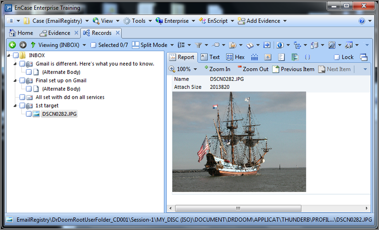
Often, examiners encounter non-image Base64 attachments, such as documents, spreadsheets, ZIP files, and the like. EnCase automatically processes them as well. They are also decoded and displayed as they were attached by the sender. If you wanted to see its contents, you could right-click and tag the file. Once in the Entries view, you could double-click the ZIP file. EnCase would pass the file to the application registered by Windows to open ZIP files, and you could view the contents of the ZIP file in the Windows environment. Alternatively, you could go to the Entries view, locate the ZIP file, mount it (right-click and choose View File Structure), and view its contents within EnCase.
When Base64 attachments appear in the unallocated clusters, they usually require manual processing to extract them. Before you can extract them, you must find them. Base64 encoding has header information, some of which is unique and consistent, and it has a footer or marker to establish its endpoint. Figure 10-49 shows the header information that precedes Base64 data. By searching for strings associated with these headers and footers, you can locate Base64-encoded data in the unallocated clusters or wherever it may occur. These strings are base64 and _NextPart_ (these strings are case-sensitive).
If the Base64 attachment is an image, finding the header information is usually sufficient because EnCase’s internal viewer can view the encoded data by simply bookmarking the first byte of the encoded data. In Figure 10-49, I have placed the cursor on the first couple of bytes of the Base64-encoded data of a JPEG image. To display the image, simply switch to the Decode tab, and under View Types, choose Picture, and under Picture, chose the Base64 Encoded Picture option, as shown in Figure 10-50.
Figure 10-49: Base64 header information that precedes Base64 data, noting the search hits on the previous strings
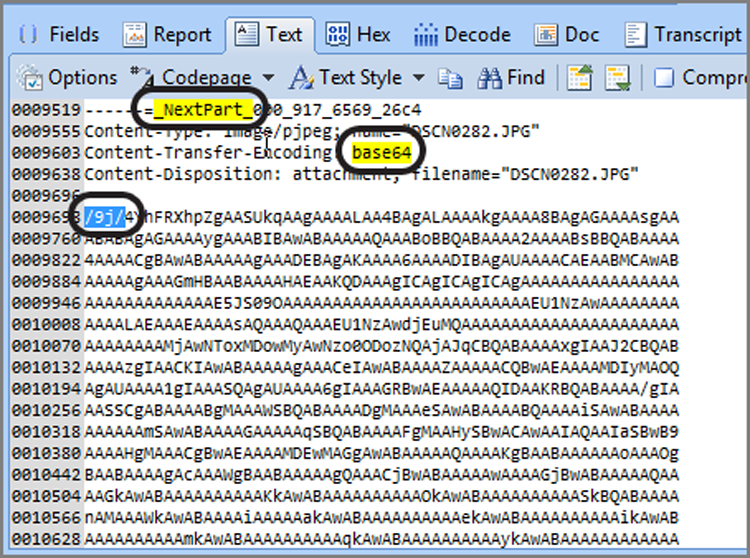
Figure 10-50: Place the cursor on the first byte (or more) of Base64 image data and view it in the Decode tab as a Base64 Encoded Picture.
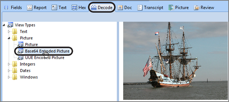
![]()
Just as you can search for JPEG headers by searching for the string \xFF\xD8\xFF[\xFE\xE0\xE1], you can search for a JPEG image encoded in Base64 by using its unique header. The string for this search is /9j/4Yh. This is not a GREP search and should be run with case sensitivity enabled to make your search both fast and precise.
EnCase Decryption Suite
EnCase Decryption Suite (EDS) in previous versions of Encase was an extra-cost module; however, with EnCase 7, EDS is integrated into the program at no extra charge. EDS has grown and evolved with the growth of encryption schemes and products. The help screen in EnCase, shown in Figure 10-51, shows quite vividly the depth of complexity and support offered with this feature. Currently (version 7.04), EDS supports the following forms of encryption:
· Disk and volume encryption
· Microsoft BitLocker
· GuardianEdge Encryption Plus/Encryption Anywhere/Hard Disk Encryption
· Utimaco Safeguard Easy
· McAfee SafeBoot
· WinMagic SecureDoc Full Disk Encryption
· PGP Whole Disk Encryption
· Checkpoint FDE (Full Disk Encryption)
· File-based encryption
· Microsoft Encrypting File System (EFS)
· CREDANT Mobile Guardian
· RMS
· Mounted files
· PST (Microsoft Outlook)
· S/MIME-encrypted email in PST files
· NSF (Lotus Notes)
· Protected Storage (NTUSER.DAT)
· Security hive
· Active Directory 2003 (NTDS.DIT)
· EnCase Logical Evidence file Version 2 Encryption
Figure 10-51: The EnCase help feature for EDS depicts supported encryption products.
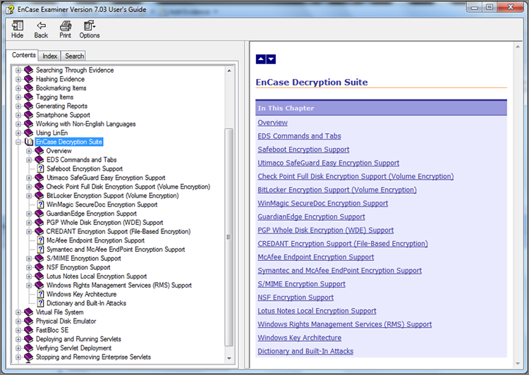
Much of what EDS does is in the background, while some of its functionality requires examiner action. For example, when an image is added to a case, the master boot record area of the drive is scanned for signatures of known encryption schemes. If encryption is found, EDS will intervene and prompt the user for the credentials for that product so it will be able to decrypt it.
Soon after adding an evidence item to a case, an examiner should run the analyze EFS routine against each volume in the case. This will allow the EDS module to extract valuable information from the operating system drive for the purposes of decrypting various encrypted files or data streams. The information will be used to populate the Secure Storage view.
To run the Analyze EFS module, right-click the device in the Tree pane. Under Device options, choose Analyze EFS, as shown in Figure 10-52. You will immediately receive a confirmation menu advising you what you are about to do and to which volume; simply click Next to proceed. On the screen that follows, you’ll have to either confirm or provide the path information for the Documents and Settings folder and the registry, as shown in Figure 10-53. Once you confirm these settings and click Next, the Scan EFS module will run. Upon completion, a screen will appear indicating the result of the scan, as shown in Figure 10-54.
Figure 10-52: Analyze EFS on right-click menu under device options
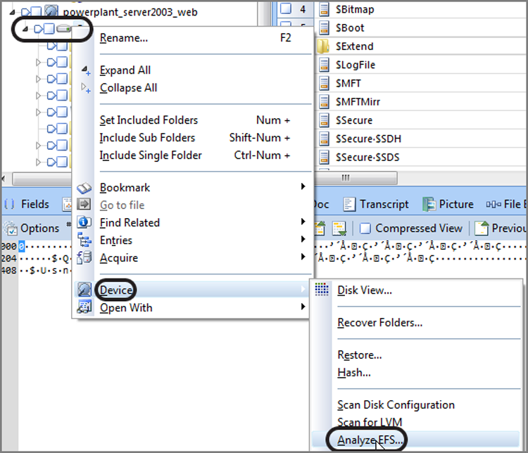
Figure 10-53: Menu by which to confirm or edit paths to Documents and Settings and registry
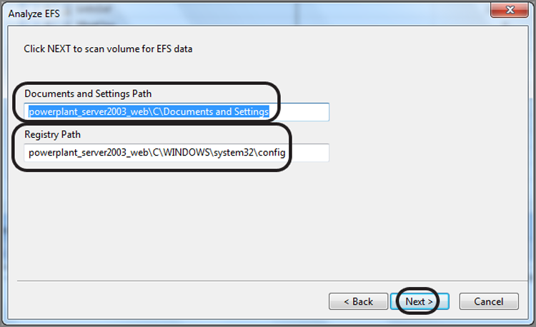
Figure 10-54: Results of EFS scan
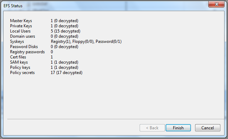
The Secure Storage view, found on the View menu, is the repository and interface for the EDS module, which includes the results of the EFS scan, as shown in Figure 10-55. From this view, many types of security data can be manually entered, including passwords, user/SID combinations, keys, and so forth. The super-secret menu button at the far right of the Table toolbar provides access to several data-entry tools, as shown in Figure 10-56. The Enter menu, shown in Figure 10-57, allows you many types of password/security entries, all of which are fully explained in the EnCase User Manual. The User List menu, shown in Figure 10-58, allows you export usernames, SIDs, and hashes. Additionally, there are tabs adding users in both Windows Domains and Unix environments.
Figure 10-55: Secure Storage view populated with data from EFS scan
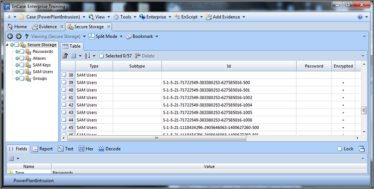
Figure 10-56: This super-secret menu (circled triangle) provides access to various entry menus (circled).
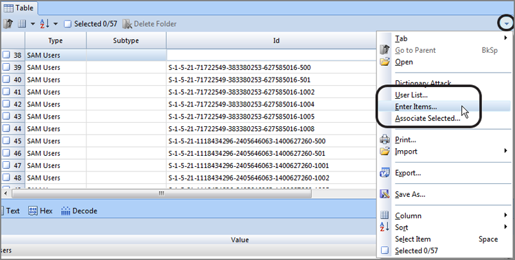
Figure 10-57: Enter items dialog box allows entry of various passwords and keys
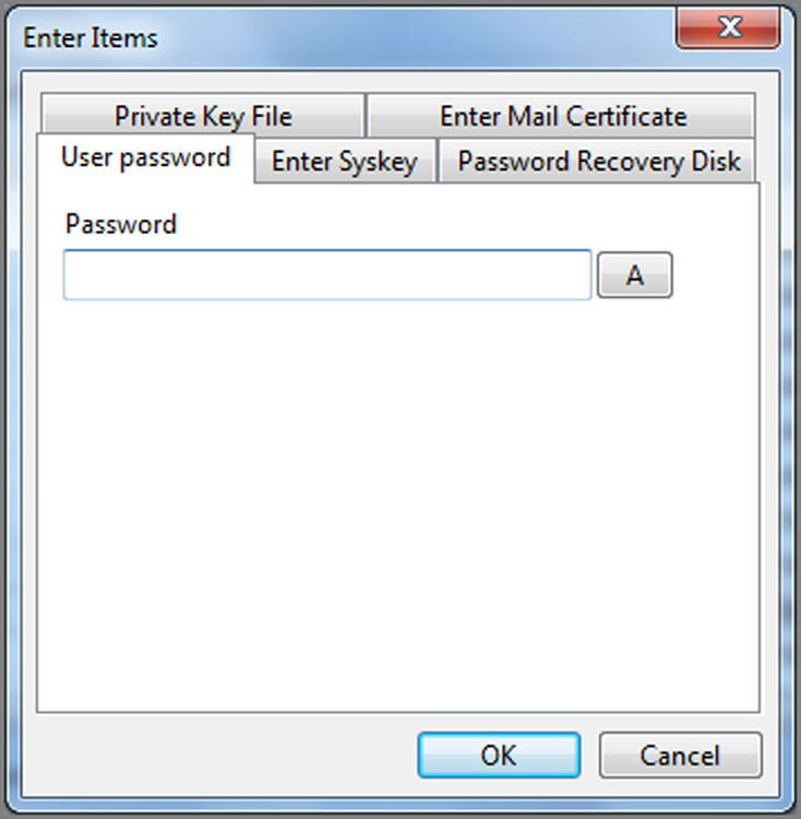
Figure 10-58: User List dialog box allows exporting of hashes for password cracking and entry of Windows or Unix users
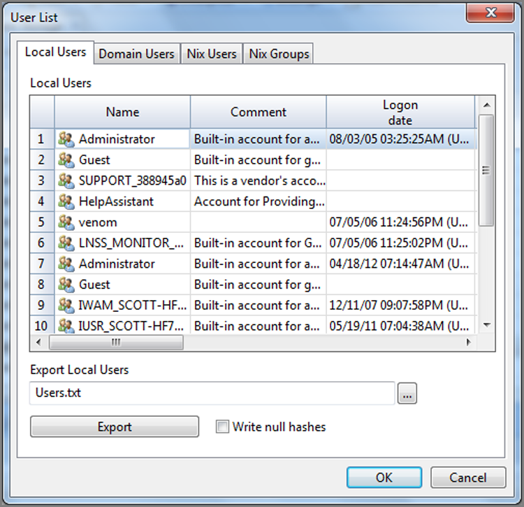
Guidance Software publishes a manual for EnCase, which includes extensive documentation for the EDS module. Working with encryption can become rather involved, and this manual covers the topic in depth. It is updated periodically as new releases of EnCase become available and new encryption products are supported. You can locate it easily on Guidance Software’s website under Download Center in the Support section. It also is provided in an email link when you register your dongle.
Cool Tool in EDS!
When you right-click a volume in the Tree pane view and choose Analyze EFS, many things happen, most of which are complex and far exceed the scope of this book. One thing that happens is that the syskey is extracted from the system file and used to decrypt the password hashes stored in the Security Accounts Manager (SAM). That this occurs is not readily apparent, and likewise getting at this information is even more obscure. If, however, you go to the Secure Storage view, after running Analyze EFS, you can easily access this information. In the Secure Storage view, right-click in either the Tree view or Table view pane, choose User List, and look at the Local Users view. Because this window is fixed size, the good information is not in view. If you use your horizontal scroll bar, you can look at the password hashes hidden to the right.
In the browse feature in the lower half of the window, choose a convenient location, call the file something like hashes.txt, and choose Export. What you now have is a password hash file created in the pwdump format and ready for additional processing. It should look something like this:
Administrator:500:99050cc8594bac75889941946374a88f:c21e061704a3fe4fa087babc097c25f0249b:Built-in account for administering the computer/domain::
Jay L. Bird:1003:f03fd06248a220c9648d2484dbc4b29d:f9adf23e9ec3a3c60aa1aee6de72d433:::
This functionality saves the user from exporting out of EnCase the system and SAM files and having to use third-party tools to extract the syskey and subsequently use it to decrypt the hashes from the SAM. EFS does this for you all within EnCase. You need export only the resultant text file as described earlier.
If you’re not familiar with the next step, you can use several tools to crack the password from the hash. Some use dictionary attacks, while others use brute force, but you can’t beat rainbow tables for the task at hand.
To use rainbow tables, you first must have them. Shmoo’s website (http://rainbowtables.shmoo.com/) has a torrent you can use with BitTorrent to download the tables. The best to get is the alphanumeric-symbol32-space LanMan tables. It will take you three or four days to download them on a fast connection. When they’re unpacked, they occupy about 64 GB of drive space. That being said, you’ll need to plan for significant drive space on which to store the download and subsequent decompressed files.
Once you have the tables and Rainbow Crack, both of which are free, you need run only the Rainbow Crack command-line tool, pointing it at the tables and the file you extracted from EnCase. You will also be using the -fswitch, which signifies the file is in the pwdump format. Assuming the hash text file exported from EnCase is in the same location as the rcrack tool and that the tables are in subfolder of the same location, the command will take on the following syntax:
rcrack \tables\*.rt -f hashes.txt
After you run this command, go on about your business. If you have two accounts, such as those shown earlier, to process on an average-speed machine, you have your passwords cracked in less than two hours. In a recent test of more than 200 users from an Active Directory pwdump, Rainbow Crack resolved 100 percent of the passwords in just less than 24 hours.
Naturally, this technique won’t work if the LanMan hashes are disabled or the user has a password that is 15 characters or longer in length. In practice, however, rarely will you encounter either circumstance with the typical user.
Bad and Good News from Microsoft
Windows Vista (and Windows 7 as well) ships with the LanMan hash disabled, meaning that there is no more easy cracking with rainbow tables. Instead, you’ll have to attack the stronger NTLM hash, which you can export from the User List as described earlier and use the NTLM hashes and against NTLM rainbow tables instead. That’s the bad news.
There is, however, some good news. Microsoft has provided some rather surprising assistance because Windows Vista has a new registry value in the SAM at Domains\Account\Users\<RID>\. The value name is UserPasswordHint. If you can believe this, the value is stored in plain text. This appears, naturally, only if the user has provided a password hint, but many do, and it appears in the clear. Thus, if you have to attack the NTLM hash, look here first!
Virtual File System (VFS)
VFS enables you to mount evidence as a read-only, offline network drive. As such, the mounted volume is available in Windows and can be browsed with Windows Explorer or examined by third-party tools. VFS is no longer a separately purchased module but rather included in EnCase 7, thus providing added functionality with the basic software package.
EnCase treats the unallocated clusters as though they were logical files, and when the evidence volume is mounted, the unallocated clusters are addressable within Windows. As an added bonus, all deleted files and folders are available as well. Figure 10-59 shows an EnCase evidence image that has been mounted using VFS and is then available as a network drive in Windows. The unallocated clusters are showing as one 23 GB file; you also have access to the Lost Files folder and all files and folders in it.
Figure 10-59: An EnCase evidence file mounted with VFS and appearing as a network drive in Windows
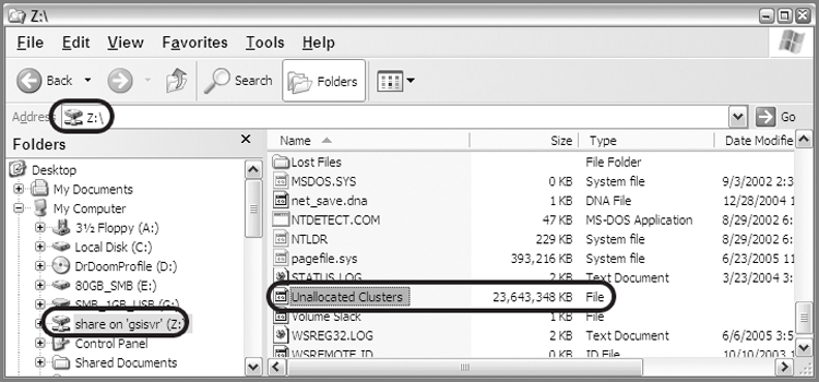
If EnCase supports the image file type, VFS will mount it. EnCase supports EnCase Evidence Files, dd images, SafeBack (V2) images, and VMware images. In addition, live computer forensic devices can be mounted with VFS and include a local machine preview of removable media, a local machine preview using any of the FastBloc or Tableau write-blocking devices, and EnCase Enterprise or FIM (version 6) live network previews.
Interestingly, all file systems that EnCase supports can be mounted with VFS in Windows Explorer. Currently, the list of supported file systems includes the following:
· Windows file systems (FAT 12, 16, and 32 and NTFS)
· Linux file systems (Reiser, EXT2, EXT3)
· Unix file systems (Solaris UFS)
· AIX Journaling File System (JFS and .jfs)
· LVM8
· Macintosh (HFS, HFS+)
· BSD (FFS, UFS2, which is also called FFS2)
· TiVo 1 and 2
· Novell NWFS and NSS
· CD/DVD (Joliet, ISO 9660, UDF, DVD, HFS)
· Palm (Palm OS)
VFS can mount only one mount point at a time, but it can mount at four different levels: the case level, the disk/device level, the volume level, or the folder level. Whichever level you choose, before you can change to another level, you must first dismount the current mount, because you can have only one mount point at any time.
To perform a VFS mount, choose the level for your mount by placing it in the Table pane and highlighting it. Right-click the level/object to mount, and choose Mount As Network Share from the Device > Share menu, as shown in Figure 10-60.
You will be prompted next with a Mount As Network Share dialog box, where you will click OK, accepting all defaults. Figure 10-61 shows this dialog box.
After you click OK, the mount will occur, and you will see a pop-up box informing you of a successful mount and the location of the mount, as shown in Figure 10-62.
When you are done, the various devices in your case will be available under one network share drive letter in Windows. In the previous example, we simply mounted a Windows volume. As an example of the versatility and power of this future, in another case we had evidence devices that consisted of two Windows file systems (FAT 32 and NTFS), a Macintosh OS X file system (HFS+), and two Linux file systems (EXT2). Amazingly enough, all these disparate file systems were made available in Windows Explorer by applying VFS at the case level, as shown in Figure 10-63. VFS can also mount EnCase Logical Evidence Files, and it is an integration point for processing collected and preserved data for electronic evidence discovery (eDiscovery) in civil litigation.
Figure 10-60: VFS is activated from the right-click Device > Share > Mount As Network Share menu.
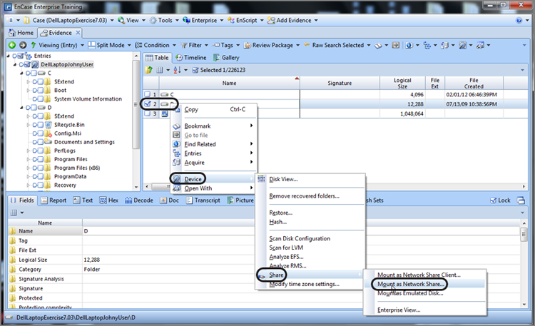
Figure 10-61: The Mount As Network Share dialog box; accept the defaults and click OK
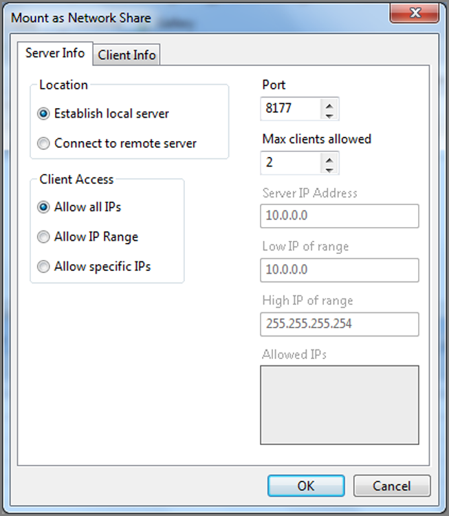
Figure 10-62: Virtual File System is running and gives the drive letter for your mount.
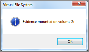
Figure 10-63: Windows, Macintosh, and Linux file systems are all available simultaneously in a Windows interface through one VFS mount point applied at the case level.
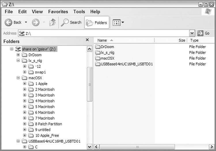
Once mounted, the possibilities for third-party examinations are seemingly endless. At the least, a thorough examination should include a virus scan and a spyware/Trojan scan with at least two different products to be thorough. VFS simplifies this task greatly, saving much time and money compared to other methods of achieving the same task.
To dismount or end VFS, the user must double-click in the lower right of the EnCase screen where the label Virtual File System is constantly blinking while VFS is running. When you double-click this blinking label, you will receive a prompt asking whether you want to cancel the VFS process, which you confirm by clicking Yes.
As with the EDS, Guidance Software documents the VFS function in the EnCase User Manual, which is available on its website. Advanced features and techniques are described in this publication.
Restoration
Restoring the evidence file to another drive produces a cloned drive that can be used for many purposes. Often, this technique is used to boot the suspect’s machine with the cloned drive to conduct a myriad of special examinations, ranging from restore point analysis to using applications on the system. Also, using this method, you can see the system very much as the suspect did, which can provide valuable information that is difficult to obtain any other way.
EnCase provides the option to restore either the logical or physical drive. If your original evidence is a physical device, restoring the logical device only does not allow for verification as an exact copy. Usually, the physical drive is the best method for restoration, especially if your intent is to boot the suspect drive after restoration.
When restoring, EnCase copies everything at the level selected (logical or physical), sector by sector, to the target media. The drive you’re restoring to must be of equal or larger size. When the restoration is complete, EnCase will verify the restoration and provide hash values of the restored drive. If the target drive is larger, as it often will be, the excess sectors are not included in the verification hash because the hash value represents only the number of sectors restored. The examiner should understand this, and a separate MD5 hash of the restored drive must be conducted only on the restored sectors for the values to match.
![]()
One 500 GB hard drive model will most likely have the same number of sectors as another model rated at 500 GB, but then again it may not. When you select a drive to restore to, compare the number of sectors to determine whether the target drive is of equal or larger capacity.
You may optionally wipe the target drive before restoring to it, but this is not necessary because EnCase provides the option to wipe any remaining or unused portion of the drive after all the sectors have been restored. Once you have selected an appropriate target device, mount it in Windows.
To restore an image, at either the logical or physical level, begin in the Tree pane of the Case view. Alternatively, you could force the physical or logical device, from which you want to restore, into the Table pane and work from there as well. From either location, select either the logical or physical device icon, right-click it, and choose Restore, under the Device options. EnCase displays the Restore dialog box, which is a large, boring gray box with the choice of only Cancel or Next. Choose Next, which will collect local devices to which you can restore. In the screen that follows, shown in Figure 10-64, you specify the local device for restoration. Since the source of my restoration is the physical drive, I plan to restore to the physical drive. Thus, I have chosen physical device #1, which is a 4 GB USB drive. Click Next for the next step, which is to select some final options.
![]()
As a safety measure, EnCase will not display the volume (drive letter) on which Windows is running.
Figure 10-64: This dialog box lets you select the target drive for restoration.
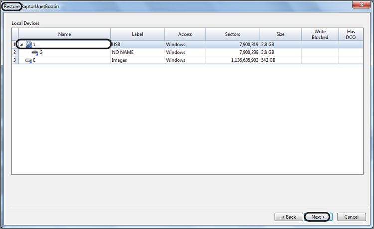
After you choose the target drive for the restoration, EnCase provides some final options before the restoration begins. Those final options are displayed in the Drives dialog box, as shown in Figure 10-65. The first option is Wipe Remaining Sectors On Target, which, when selected, causes any remaining sectors on the drive to be wiped. The second option is Verify Wiped Sectors. This option name does not accurately describe its function. Its actual purpose is to cause EnCase to verify the restored sectors, comparing the acquisition hash value with the hash value of the restored sectors. The final option is to choose the characters used for wiping the remaining sectors. The default value is 00h but can be any hex value you specify. When you are ready, click Finish. EnCase will prompt you by asking you whether you want to proceed, as shown in Figure 10-66. Type Yes, and click OK to confirm and start the restoration.
Figure 10-65: Drives menu in which final options are selected. Accept all defaults!
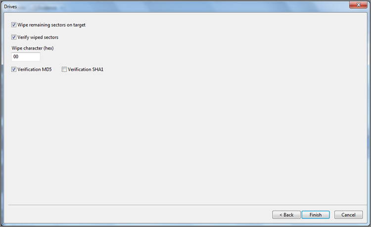
Figure 10-66: Final confirmation and warning
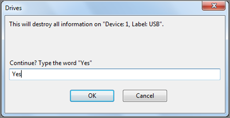
When the restoration is complete, the progress bar will disappear, and there will be no pop-up completion reports as with past versions of EnCase. Immediately remove the drive from Windows to prevent Windows from eventually discovering it and writing to it. The information pertaining to the restoration task will be recorded in a log record. From the View menu, choose and open Log Records. In the Log Record view, locate the Restore task, open it, and review the details. The acquisition and verification hashes should match. Other information will be available, as shown in Figure 10-67.
Figure 10-67: Restore and verification data is contained in a log record.
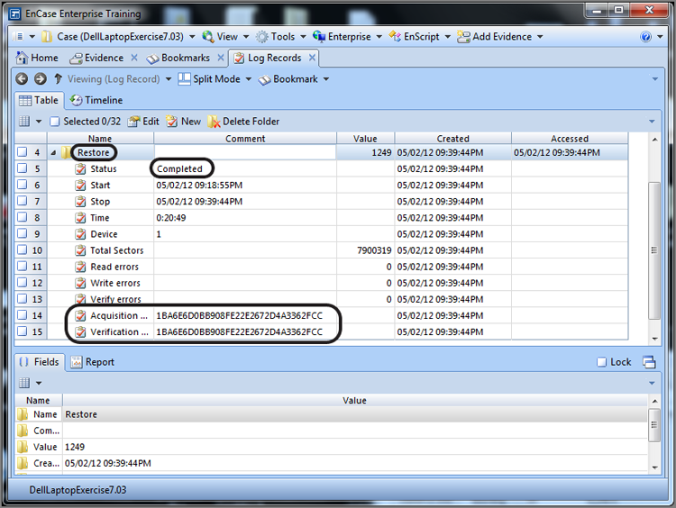
As a final note, if the restoration is to be made of a logical device, your preparation will be somewhat different. A logical volume must be restored to a volume of the same type and of equal or greater size. If the evidence file volume to be restored is NTFS and 500 MB in size, the target volume must be formatted to NTFS and must be 500 MB or larger in size. To determine the size and properties (partition type) of the evidence file volume, refer to the Report view for the volume. When you restore the logical volume, make sure you select the logical drive letter of the target drive.
Physical Disk Emulator (PDE)
The Physical Disk Emulator (PDE) module is similar to the VFS in many ways, but there are some clear and distinct differences:
· PDE can mount only a physical disk or volume. VFS can also mount an image file.
· When PDE mounts a disk or volume, Windows treats it as a disk or volume. Windows treats a VFS-mounted item as a network share.
· PDE mounts file systems supported by Windows. VFS mounts any file system supported by EnCase.
· With VFS you can see unallocated clusters, deleted files, and recovered partitions.
· With PDE, you can use VMware to mount a disk as a virtual machine.
When PDE mounts a disk or volume, it will appear in the Windows Logical Disk Manager, which is a service that starts when there is a need to configure hard disk drives and volumes and stops when that process is done. Figure 10-68 shows the Windows Logical Disk Manager after a 1.8 GB physical drive has been mounted within EnCase using PDE. This mounted drive shows as physical disk 3 and is further mounted as drive letter F.
Figure 10-68: Windows Logical Disk Manager displays a PDE-mounted disk.
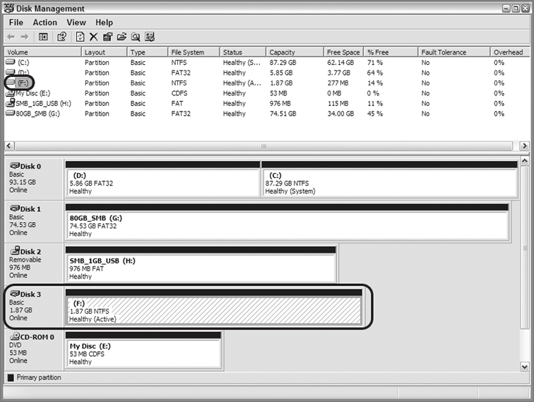
The process of mounting a physical device or volume with PDE is similar to that of mounting with VFS. First, select the physical or logical device to mount by placing your cursor on it, right-click, and choose Mount As Emulated Disk, which will be under the Devices > Sharing options, as shown in Figure 10-69.
Figure 10-69: Location of Mount As Emulated Disk feature
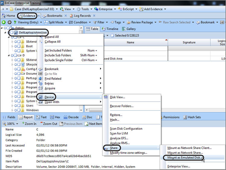
You will see the Mount As Emulated Disk dialog box, which should default to the Server Info tab, as shown in Figure 10-70. A local port is assigned to the mount, and the number will appear in the window, which can be changed if you like. Once the port is in use, it remains assigned for all future mounts. To release this port and assign another port, you need to restart Windows. (This issue or process is really rather academic because I’ve never seen a reason to change the default port or change it after it was assigned. But if you encounter that need, you now know the rules!)
A second tab is available in the Mount As Emulated Disk dialog box. The Client Info tab, as shown in Figure 10-71, provides certain advanced options. If a multisession CD is mounted, you can choose which sessions you want to mount. If you are using VMware (discussed later in this section), you need to enable caching per the set of instructions for setting up VMware. Caching allows files to be added, modified, or deleted as needed and to have these changes cached to a file for use by VMware. In addition, these cached files can be saved and reused in future sessions. When you start the mount, you will likely get a warning from Windows that the publisher of the driver can’t be verified. If so, choose the option to install the driver anyway. You stop or end PDE in the same way you would VFS, which is by double-clicking the blinking Physical Disk Emulator in the lower-right corner.
Figure 10-70: The Mount As Emulated Disk dialog box showing the Server Info tab
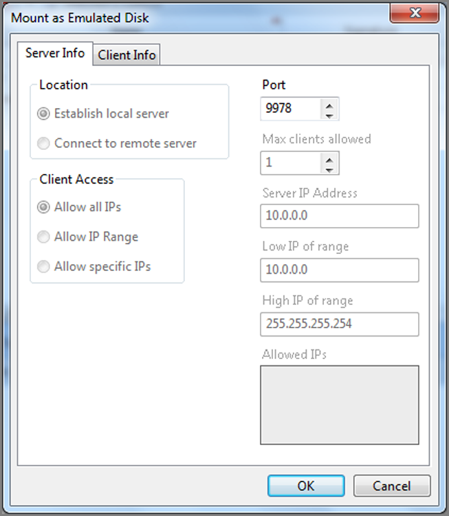
Figure 10-71: The Client Info tab of the Mount As Emulated Disk dialog box
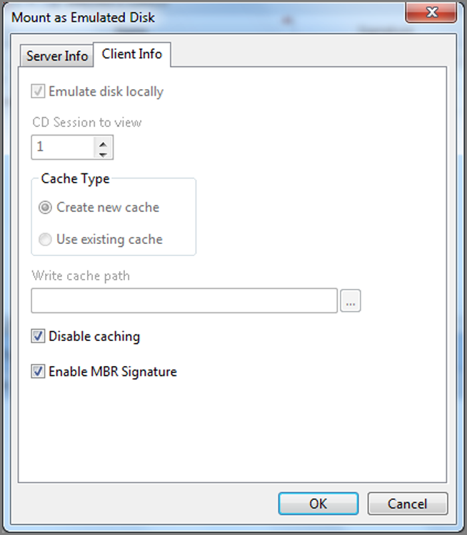
PDE supports the same evidence file formats and live computer forensics evidence as does VFS. When PDE mounts in Windows; however, only file systems recognized by Windows will be supported and mounted, which means only NTFS and FAT. If neither the NTFS nor FAT file system is present, no file system will mount, but the physical device will be available. As you’ll recall, by contrast, VFS will mount in Windows any file system supported by EnCase.
![]()
Don’t use PDE to mount EnCase images or previews of a local hard drive. If Windows detects multiple instances of the same drive on the local box, you will likely experience the proverbial Blue Screen of Death (BSOD).
Another subtle difference between PDE and VFS is that PDE presents the physical disk or volume as is to Windows, whereas VFS presents the file system as EnCase sees it. What does this really mean? Windows can’t see unallocated clusters, and when PDE presents a physical disk to Windows to mount, you won’t see unallocated clusters in Windows Explorer. Quite by contrast, when you mount using VFS, EnCase treats the unallocated clusters as one contiguous logical file, and that logical construct is passed to Windows when VFS mounts. With VFS, unallocated clusters are viewable in the Explorer interface.
The same rule or logic applies to deleted files. As EnCase undeletes deleted files and displays them, VFS presents this logical reconstruction of deleted files to Windows when VFS mounts; thus, deleted files will be viewable in Windows Explorer with VFS. With PDE, don’t expect to see deleted files.
These differences are subtle, but the difference is truly magnified in the case of a recovered partition. If you recover a partition with EnCase and mount the physical drive with PDE, Windows sees only the physical disk and can’t mount the recovered partition since it is not there. By extreme contrast, if you mount the same physical drive with the recovered partition using VFS, the recovered partition as EnCase sees it is passed along to Windows, and you can see the entire partition in Windows Explorer.
It is important to understand the similarities and the differences between the two modules; clearly some tasks are module specific, while some tasks can be carried out in either. For example, if your intent is to process the unallocated clusters, you need to use VFS. If your intent is to scan for viruses or malware, either module will suffice.
One of the most popular capabilities of PDE is that of using it in conjunction with VMware. When you have the physical disk or volume mounted in Windows as a physical disk, VMware can take that physical disk and mount it as a virtual machine. This means you can often virtually boot and run your suspect’s drive totally within the EnCase and VMware combined environments. This can save considerable time and expense compared with the traditional method of restoring the image to a drive and booting it in the suspect’s box.
The entire process of using VMware with PDE as well as the advanced features of the PDE module are well documented in the EnCase User Manual provided by Guidance Software. PDE, like VFS, is now included with EnCase and no longer requires a separate license and fees.
Often the question arises as to which module, PDE or VFS, should be used for which task. Table 10-7 lists various tasks and the proper module (VFS or PDE) for the job, along with a brief description of the reason.
Table 10-7: Forensic tasks and the proper module (VFS or PDE) for the job
|
Task |
Module |
Rationale |
|
Running a virtual machine using VMware |
PDE |
VMware needs access to a physical disk. |
|
Virus or malware scan |
PDE or VFS |
If not interested in deleted files, use PDE. If interested in deleted files, use VFS. |
|
Extracting Internet history from unallocated clusters |
VFS |
PDE does not provide access to unallocated clusters. Only VFS provides this access. |
|
Using Windows Explorer to peruse Linux or Macintosh file systems |
VFS |
PDE allows the mounting of only those file systems supported by Windows. VFS mounts any file system supported within EnCase. |
|
Using any third-party tool in Windows to examine a partition recovered in EnCase |
VFS |
With PDE, Windows won’t see the recovered partition. VFS presents the file system as EnCase has restored it. |
Putting It All Together
Together we have covered the gamut of the major features of EnCase 7. The order in which we have proceeded was largely determined by the most logical learning progression, which has no connection to the order in which you might conduct a forensic examination. So, what is the best order in which to conduct a forensic examination? Clearly, there are a few basic steps that progress in a certain sequence, but beyond that, the order is most often determined by the examiner based on the nature and urgency of the case.
Over the years, many examiners have asked for a list of suggested steps for an examination. Over time, with input and suggestions from many colleagues, I have assembled such a list. It should never be regarded as mandatory or as a standard. Rather, consider it a suggested approach that is dynamic, flexible, and rarely if ever all-inclusive. Every case is different, and both the tools and the computing environment are in a constant state of change. Also, please keep in mind that any search (hash analysis included) must be conducted within the scope of your search authority. With those caveats and conditions stated, the list of suggested steps follows:
1. Log your case information into your lab case management database or casebook.
2. Examine and document the computer systems under examination, taking care to conduct both an internal and external inspection and carefully recording your findings in photos, notes, or forms created for that purpose.
3. Determine the method of acquisition, preview (if applicable), and acquire the image of the media.
4. Make certain that all sectors on the drive have been identified and actually acquired (determine whether HPA or DCO is present).
5. Make a backup copy of all images, store the original in a secure location, and conduct your examination on copies.
6. Obtain the system times from all machines under examination, and simultaneously record the known time from an accepted time standard.
7. Once images are acquired and brought into the case, make certain that the file integrity is verified.
8. Preview the images acquired. Determine the total sectors on the various devices; reconcile those sectors with sectors in partitions to make certain all partitions are mounted and accounted for. Recover and mount any deleted partitions.
9. Determine time zone offsets for all devices and modify time zone offsets according to case requirements. Usually you want all offsets to be uniform across the case.
10. Run Analyze EFS on all volumes.
11. Run the EnCase Evidence Processor. Run: Recover Folders, File Signature Analysis, Expand Compound Files, Hash Analysis, and Protected File Analysis at a minimum. Depending on your case (nature of investigation, time constraints, and so on), also run Find Email, Find Internet Artifacts, Index Text, Windows Event Log Parser, File Carver with web mail option, and Windows Artifact Parser.
12. While EEP is running, review obvious artifacts in the folder structure. Look at the user’s desktop, documents, pictures, favorites, and recent folders. Review the Internet cache in Gallery view to get an overview, pictorially, of the browsing activity. Look in the Recycle Bins for deleted files or signs of recent purging of files. Process the UserAssist key with a third-party tool to see what programs have been recently run and how frequently. Follow this up with a review of the prefetch files. Look in the program folders and see what programs are installed. In short, get a good handle on the user’s activities. If any programs of import are being used, take note and follow up (hacking tools, forgery tools, and so forth, for example)
13. While EEP is running, review information collected during incident response. Review the volatile data capture report, noting any anomalies regarding running processes, open ports, and so forth, that may have a bearing on the case. If the case warrants, examine RAM memory that was acquired.
14. Determine whether the computer is being used remotely via Remote Desktop, or other like tool.
15. Run a condition to determine whether EFS encryption is applied anywhere (the description contains encrypted).
16. Using VFS or like tool, conduct a malware scan. If machine is compromised, you need to know early on in the case, not near the end.
17. Review link file analysis (completed by EEP) and determine whether there are other drives (external or network) that are missing. Review also the USBStor registry key for recently attached USB drives. In short, make sure all media being accessed and of apparent import has been secured for examination. If not, make certain to take proper action to obtain it.
18. Complete link file analysis, following up as needed.
19. Run Case Analyzer EnScript. Under Windows Artifacts, review Link Files, Recycle Bin, MFT Transactions, and other reported data. Under Internet Artifacts, review history, cache, cookies, bookmarks, and downloads. When reviewing history, look for frequency patterns in browsing activity. Under System Info, review users and accounts, network settings, shares, and mapped drives. If Personal Information is parsed, review.
20. Review results of file signature analysis (use condition to focus on files having an alias in the Signature column).
21. Review results of hash analysis. Look for presence of notable files first and those in hash sets next. Conditions are great for this task.
22. On Records tab, review thumbnails for images of import.
23. On Records tab, review email for messages and attachments of import.
24. As review of documents, files, and so forth, occurs, if password protection is encountered, develop strategy to decrypt (low-hanging fruit passwords, create lists of strings for dictionaries, compile biography of suspect for added dictionary words, determine best decryption tools, and commence cracking task).
25. Search index for relevant keywords. If necessary, conduct raw keyword searches for relevant keywords.
26. Process restore points/volume shadow copies as indicated by case specifics. Such may require restoration of drive and booting of suspect’s machine. Voom Shadow drives are quite useful for this purpose.
27. Search for and process artifacts of past print jobs from deleted spool files.
28. Locate instant messaging clients and process any artifacts or messages that may be logged.
29. Locate any peer-to-peer file sharing software. Process the associated artifacts.
30. Locate financial software and process any associated databases in their native environment.
31. Examine Photoshop files in their native environment to check for images or text data that may be hidden in layers. EnCase doesn’t see underlying hidden layers!
32. Run third-party tools on mounted devices using VFS or PDE as may be indicated.
33. Examine log files (Windows event logs, setupapi.log, web server logs, FTP logs, error logs, AOL logs, and so on).
34. Examine the Windows event logs for the time period in question. Make certain the sequential numbering of the records is in sync with the chronological sequencing. (In short, examine for alterations of the system time.)
35. Carve files from free spaces of file types indicated by case.
35. Conduct any other specialized inquiries as may be dictated by the specifics of the case.
36. Use PDE to mount physical device and run VMware to boot the suspect’s drive to see it as the suspect saw it. Alternatively, restore the image out to a drive and use the restored drive to boot the suspect’s computer, again viewing their system as the suspect saw it.
37. Run an end-of-case Verify File Integrity check, and bookmark your findings.
38. Bookmark all significant findings, organize bookmarks, and create your final report.
39. Use the Create Package feature to archive all case data onto archival media, verifying copies of evidence files.
This is, again, a suggested list and one that you can customize and modify as circumstances warrant. You will probably find that the first half of the list contains steps you’ll need to do in most every case and quite often in the order presented. After that, the nature of the case starts to guide your approach. The last three steps trend back to obligatory tasks or best practices. Lists are helpful, but you should avoid getting into a checklist trap, where you methodically process according to a standardized checklist. Such an approach becomes habitual and can inhibit creativity and examinations that are beyond the list or out of the box.
Computer forensics is an extremely dynamic field, one in which the playing field is constantly changing. New technologies are evolving daily. As examiners, we should be reactive to trends and be able to adapt rapidly to changes.
Up until around 2005, give or take a couple of years, computer forensics examiners were generalists. Today, things have changed. Computing in general has become far more complex than it was seven years ago. One can no longer be an expert in all areas; the field has become too vast. Specialty areas are emerging. Not only must you be a generalist, but you must also develop specialties based on the type of work in which you are immersed. The age of computer forensic specialty areas is here, and there’s only one direction it can go: up.
If you think about the development over the past 5 to 10 years and try to imagine what computing will be like in 5, 10, or 15 years, it is simply too much to even comprehend. Computers are trending toward smart devices that we carry with us. Just how those trends will play out, only time will tell. We will be facing technologies that we cannot even begin to imagine today. As always, training and education will be the keys to meeting these new challenges.
Although training and education are important, they aren’t the complete solution. One person can’t possibly begin to be an expert in all areas, so we must develop strong informational networks among computer forensics examiners. Information-sharing networks allow us to share knowledge and techniques and foster problem solving in real time, regardless of your geographical location.
With those parting thoughts in mind, if we are to meet the challenges of the future of computer forensics, we all need to embrace a couple of simple goals. First, we must put aside our differences and all work together to form and nurture informational networks. Finally, each of us must make a commitment to excellence and seek out all possible education and training opportunities. We now live in an information age, and the more information we have, the better off we’ll be in facing the challenges of the future.
In the field of computer forensics, excellence is not an option; it is an operational necessity. Excellence, on the individual level, is a combination of integrity, perseverance, a commitment to the highest standards of the profession, and a never-ending thirst for knowledge through research and education.
My best wishes and regards to you on your EnCE certification testing and in your career.
Summary
In this chapter, I covered a wide array of advanced techniques and concepts. I began with a review of the previous discussions of partitions as a predecessor to recovering them when deleted. The partition table is located in the MBR at byte offsets 446–509. In those 64 bytes, up to four partitions can be described in 16-byte strings. When one or more partitions are deleted, their corresponding entries in this table are removed and replaced with zeros. This is often described as fdisking.
Even though the entry in the table may be zeroed out, the VBR marking the beginning and containing the parameters of the partition often remains untouched, depending on where it is and what subsequent actions have taken place.
When the first partition is missing, you can usually look to the first sector of the second track to find the VBR. With that located, you can restore the partition by right-clicking that sector in the Disk view and choosing Add Partition. Usually you accept the default values, and the partition is restored by clicking OK.
When the partition is missing elsewhere on the drive, using the Partition Finder EnScript to locate VBRs works well. It is best to work in one direction, starting from the beginning of the drive, and restore partitions as they are found.
Many files are compound in nature. They can be flat files that contain objects (Office documents), they may be flat files that have a hierarchical structure (registry hive files), they can be files that are compressed (ZIP files), or they may be files that are compressed and encrypted (Outlook PST files). EnCase supports and mounts many different types of compound files. To mount a compound file, right-click it, and choose View File Structure. The resultant mounted structure may be browsed from the Tree pane/Evidence Entries tab.
The Windows registry is an enormous database containing configuration information for your hardware and software environment. The data is contained, at a physical level, in a series of hive files. The hive files are addressed by the user and programs by a logical addressing scheme that is hierarchical and similar to the files and folders used in the Explorer interface.
Instead of Explorer, the interface by which to view or edit the registry is called regedit. Instead of folders, the registry uses the term keys. The term subkey is used when it is showing a subordinate relationship between keys. Instead of files, the registry uses values. Values have three components: the value name, the data type, and the data. In regedit, the left pane is called the key pane, and only keys are viewed in this pane. The right pane is called the value pane, and only values are viewed in this pane.
The live registry consists of five root keys: HKEY_CLASSES_ROOT, HKEY_CURRENT_USER, HKEY_CURRENT_CONFIG, HKEY_LOCAL_MACHINE, and HKEY_USERS. Of these five, only the last two are master keys. The first three are derived keys that exist as links to keys within the master keys. The two master keys are the logical representation of the various physical hive files.
The hive files (BCD, SAM, SECURITY, SOFTWARE, and SYSTEM) form the hive keys under HKEY_LOCAL_MACHINE by the same names. These hive files are located in the folder %SYSTEMROOT%\System32\config, except that BCD is located on the first partition that is hidden boot partition. There is no hardware hive file because the HKLM\HARDWARE key is dynamic, created at boot, supports the booted hardware configuration, and is gone when the system shuts down.
The HKEY_USERS key consists of many hive files representing the SID numbers of the various users who have logged onto the system. Usually, there are at least three: .DEFAULT, SID, and SID_Classes, where the SID is that of the console user. The hive file for the .DEFAULT key is at %SYSTEMROOT%\System32\config\default. The hive file for the SID key is the file NTUSER.DAT, located in the root of the root user folder for the username corresponding to the SID. The hive file for the SID_Classes key is the file UsrClass.dat, located in Documents and Settings\UserName\Local Settings\Application Data\Microsoft\Windows\, where the UserName corresponds to the SID.
Registry virtualization started with Windows Vista and applications that attempt to write to protected areas of the registry have their writes seamlessly redirected to HKU\(User’s SID)_Classes\VirtualStore. Thus, this is an added area for the examiner to review.
The live registry as seen in Windows differs from the offline registry as viewed in EnCase. Volatile keys such as the HARDWARE key under HKLM will be nonexistent. Three of the five root keys are derived keys and won’t be seen as such; however, the subkeys within the master keys from which they are derived from links can be viewed. To view the registry in EnCase, simply mount any of the hive keys by right-clicking and choosing View File Structure.
EnScripts are short pieces of code that automate forensic processing or tasks. EnScripts can be used as shipped with EnCase by simply double-clicking the desired EnScript and following any prompts to configure options. For those with the proper skills, EnScripts can be created or edited within the EnCase environment. EnScripts are accessible directly from the application toolbar under EnScripts. EnCase 7 provides conditions and filters for narrowing data sets. Filters are simply specialized EnScripts that allow you to filter the case for various attributes, such as extension or file type. To create a filter, you must enter code. Conditions are filters, but the interface by which they are created is a set of dialog box options that build the code in the background for you. Filters and conditions are powerful tools. Many ship with EnCase, and conditions are easy to create. The results of filters and conditions are sent to the Results view where they can be combined into named sets using Boolean logic operators (AND and OR).
EnCase 7 (as of 7.35) supports the following email types: Outlook (PST), Outlook Express (DBX/MBX), AOL, mbox, Lotus Notes, and Microsoft Exchange Server. Email is processed within the EnCase Evidence Processor, and the results are sent to the Records view. To search for web mail, the web mail parser is selected from the File Carver, again in the EnCase Evidence Processor. Internet history and cache is parsed by the Internet Artifacts finder in the EnCase Evidence Processor. Email, web mail, Internet history, and Internet cache are all found on the Records tab. Any of these can be bookmarked individually or in selected groups. You can view the results in the Bookmark view and include them in your final report.
The EDS feature is used to decrypt data encrypted with Microsoft Encrypting File System. In some cases, the decryption is automatic, and in other cases, the password must be obtained through various cracking methods. In addition to decrypting EFS, the EDS module automatically decrypts data stored in the protected storage area of the registry. This data consists of passwords that Windows remembered for the user, and it consists of data stored for use with the autofill feature. The EDS feature has expanded to support several leading disk encryption packages, with more being added.
The VFS module mounts any file system supported by EnCase as an offline, read-only network drive. In this manner, the user can access all logical files, all deleted files that EnCase can recover, and the unallocated clusters within the Windows environment. In this way, third-party tools can be used against those logical file system objects as seen by EnCase.
The PDE module mounts the physical device or volume as a physical disk in Windows. Only file systems supported by Windows can be mounted. All other file systems will be available at a physical level only. PDE can work in conjunction with VMware to mount the suspect’s drive as a virtual machine, boot it, and see it as the suspects saw it, saving considerable time and money, plus providing another valuable examination tool.
Exam Essentials
Understand partitions, partition tables, MBRs, and VBRs. Know the location of the main partition table on a hard drive. Describe what the partition table does and what information it contains. Explain what happens when a partition is removed, particularly what is affected and what is not. Understand how to locate deleted partitions and restore them using EnCase.
Understand compound files and how they are mounted. Describe different types of compound files, and be able to provide examples. Know which compound files can be mounted in EnCase 7. Be able to describe the process of mounting files within EnCase. Explain the importance of mounting files.
Understand the purpose and function of the Windows registry. Explain the purpose of the Windows registry. List the five root keys of the Windows registry. Know which of the five keys are master keys and which are derived keys. Explain a hive file. Know the names and locations of the hive files. Understand and explain the logical structure of the registry. Explain the difference between keys and values. Know the three attributes of a value. Describe the registry interface tool and how it is launched. Explain the difference between the live registry in Windows and the offline registry in EnCase. Explain how to mount the registry in EnCase. Explain which hive files correspond with which logical keys in the live registry.
Understand EnScripts, filters, and conditions. Explain the function of EnScripts. Know how to navigate to and run a typical EnScript. Explain the purpose of filters and conditions. Describe the differences between filters and conditions. Describe the process of creating a condition. Explain how to navigate to and run a filter or condition. Understand how to combine filter and query results and how to change the Boolean logic.
Understand and know how to conduct email examinations. Explain the various types of email clients, applications, and services. Explain the difference between an email client and web mail. Describe which email types are supported currently within EnCase. Explain the method by which email is parsed. Explain how web mail works and where to look for artifacts. Explain where parsed email can be found and how to navigate the interface and bookmark emails and/or attachments.
Understand the purpose and function of the EDS module. Explain what EFS means. Describe the system used by Windows to encrypt data. Explain what happens when a drive is mounted in EnCase and what occurs when disk encryption is encountered. Explain how to carry out Analyze EFS and where the results will be located. Describe how users’ hashes can be exported for cracking by third-party tools.
Understand the purpose and function of the VFS and PDE modules. Understand the function of the VFS module. Know which file systems will be displayed in Windows when using the VFS module. Explain the type of mount that VFS will present to Windows. Describe the various levels at which VFS can mount. Understand the function of the PDE module. Explain which file systems will be displayed in Windows when using the PDE module. Describe the primary differences between the VFS and PDE modules. Explain which module mounts deleted files and unallocated clusters in Windows.
Review Questions
1. How many sector(s) on a hard drive are reserved for the master boot record (MBR)?
A. 1
B. 4
C. 16
D. 62
E. 63
2. The very first sector of a formatted hard drive that contains an operating system is referred to as which of the following?
A. Absolute sector 0
B. Boot sector
C. Containing the master boot record (MBR)
D. All of the above
3. How many logical partitions does the partition table in the master boot record allow for a physical drive?
A. 1
B. 2
C. 4
D. 24
4. The very first sector of a partition is referred to as which of the following?
A. Master boot record
B. Physical sector 0
C. Active primary partition
D. Volume boot record
5. If a hard drive has been fdisked, EnCase can still recover the deleted partition(s), if you point to the _________ and select Add Partition from the Partition menu.
A. master boot record
B. volume boot record
C. partition table
D. unallocated space
6. In an NTFS partition, where is the backup copy of the volume boot record (VBR) stored?
A. In the partition table.
B. Immediately after the VBR.
C. The last sector of the partition.
D. An NTFS partition does not store a backup of the VBR.
7. EnCase can mount a compound file, which can then be viewed in a hierarchical format. Select an example of a compound file.
A. Registry file (that is, .dat)
B. Email file (that is, .edb, .nsf, .pst, .dbx)
C. Compressed file (that is, .zip)
D. Thumbs.db
E. All of the above
8. Windows 7 contains two master keys in its registry. They are HKEY_LOCAL_MACHINE and which of the following?
A. HKEY_USERS
B. HKEY_CLASSES_ROOT
C. HKEY_CURRENT_USER
D. HKEY_CURRENT_CONFIG
9. In Windows 7, information about a specific user’s preference is stored in the NTUSER.DAT file. This compound file can be found where?
A. C:\
B. C:\WINDOWS\
C. C:\Users\username
D. C:\Documents and Settings\All Users\Application Data
10. In an NTFS file system, the date and time stamps recorded in the registry are stored where?
A. Local time based on the BIOS settings
B. GMT and converted based on the system’s time zone settings
11. EnScript is a proprietary programming language and application programming interface (API) developed by Guidance Software, designed to function properly only within the EnCase environment.
A. True
B. False
12. Since EnScript is a proprietary programming language developed by Guidance Software, EnScripts can be created by and obtained only from Guidance Software.
A. True
B. False
13. Filters are a type of EnScript that “filters” a case for certain file properties such as file types, dates, and hash categories. Like EnScripts, filters can also be changed or created by a user.
A. True
B. False
14. Select the type of email that EnCase 6 is not capable of recovering.
A. Microsoft Outlook
B. AOL
C. Microsoft Outlook Express
D. Lotus Notes and Microsoft Exchange Server
E. None of the above
15. Which method is used to view the contents of a compound file that contains emails such as a PST file in EnCase 7?
A. Select View File Structure from the Entries options.
B. Run Find Email from within the EnCase Evidence Processor.
C. Both A and B.
D. None of the above.
16. EnCase 7 cannot process web-based email such as MSN Hotmail or Yahoo! Mail because the information can be found only on the mail servers.
A. True
B. False
17. The EnCase Decryption Suite (EDS) will not decrypt Microsoft’s Encrypting File System (EFS) on the ___________ operating system.
A. Windows 2000 Professional and Server
B. Windows XP Professional
C. Windows 2003 Server
D. Windows 7 Home Edition
18. At which levels can the VFS module mount objects in the Windows environment?
A. The case level
B. The disk or device level
C. The volume level
D. The folder level
E. All of the above
19. The Physical Disk Emulator (PDE) module is similar to the Virtual File System (VFS); the module can mount a piece of media that is accessible in the Windows environment. Select the type(s) of media that the Physical Disk Emulator cannot mount.
A. Cases
B. Folders
C. Volumes
D. Physical disks
E. Both A and B
20. The Virtual File System (VFS) module mounts data as _______, while the Physical Disk Emulator (PDE) module mounts data as _______.
A. network share, emulated disk
B. emulated disk, network share
C. virtual drive, physical drive
D. virtual file, physical disk
All materials on the site are licensed Creative Commons Attribution-Sharealike 3.0 Unported CC BY-SA 3.0 & GNU Free Documentation License (GFDL)
If you are the copyright holder of any material contained on our site and intend to remove it, please contact our site administrator for approval.
© 2016-2026 All site design rights belong to S.Y.A.