Nmap 6 Cookbook: The Fat Free Guide to Network Security Scanning (2015)
Section 0: Internet Protocol Suite
Overview
Before you can begin working with Nmap, you must have a basic grasp of how the Internet Protocol Suite (TCP, UDP, IP, etc.) works. This section provides a high level overview of the IP Suite for beginners. True to the “Fat-Free” style, this is by no means an exhaustive guide to TCP/IP, but rather a foundation to build on. The goal is to jumpstart your understanding so that you can use Nmap effectively.
Internet Protocol Suite History
The Internet Protocol Suite is a set of communication protocols that drive modern networks and the Internet. The IP Suite is often referred to as TCP/IP, short for Transmission Control Protocol/Internet Protocol, which are two of the core protocols defined in the IP Suite. Beyond TCP and IP, there are many other protocols that make up the complete IP Suite including ARP (Address Resolution Protocol), DNS (Domain Name System), DHCP (Dynamic Host Configuration Protocol), and dozens more.
The Internet Protocol Suite is the brilliant result of a United States Department of Defense project dating back to the 1960’s. The seeds for TCP/IP were planted with the creation of DoD’s ARPANET, a precursor to the Internet. The goal of ARPANET (short for Advanced Research Projects Agency Network) was to create a reliable network so researchers across the country could share computing power – which was hard to come by at the time. The solution was a “packet switched” network that could connect numerous systems to a large network backbone.
Packet switched networks break data down into tiny units of information (packets) and then relay them to the desired destination. It is a framework designed to allow bidirectional communication with multiple systems simultaneously. This is something we take for granted today in an era where everyone has the Internet in their pocket; however, before ARPANET a framework for multi-host shared network communication didn’t exist.
The ARPANET packet switching system proved to be a successful framework for networking, but as it grew fundamental flaws were found with its original design. While the core packet switching technology worked brilliantly, the initial communication protocols developed for ARPANET didn’t scale well. To remedy this, researchers decided to build an improved set of communication protocols to run on packet switched networks that would help the ARPANET grow and be more reliable. The solution was the Internet Protocol Suite.
The IP Suite was developed as a platform independent set of networking standards that run on top of packet switched networks. The primary goal of the IP Suite was to be more flexible than earlier communications protocols. It also shifted the responsibility of data integrity from the network itself to the hosts, which helped improve scalability of the packet switching system.
Throughout the 1970’s, TCP/IP was developed/refined and four different versions were created. The final version, known as TCP/IP v4, was ratified in 1981 and by the early 1990’s it had been adopted by most computing platforms. The advent of the World Wide Web combined with the power of TCP/IP and packet switched networks lead to the digital revolution that touches nearly every aspect of our lives today.
The creators of IPv4 thought of nearly everything. Reliability, scalability, and interoperability were all built into the standard. One thing they didn’t plan for, however, was the need for more than the 4.3-billion IP addresses that IPv4 provides. IPv6 solves this by increasing the address space to 2^128. That number in human readable form is:
340,282,366,920,938,463,463,374,607,431,768,211,456
To try to visualize a number that large, just imagine that IPv6 provides for the ability to assign about 4-quadrillion IP addresses to every star in the known universe. While IPv4 is still the dominant version, IPv6 is slowly emerging as its successor.
Note: Wondering what happened to IPv5? The short answer is that there is no IPv5. The Internet Protocol number 5 was assigned to an experimental streaming protocol, but it was not a successor to IPv4 and was never known as IPv5.
How The IP Suite Works
TCP/IP provides an elegant method of networking various systems together. The core architecture is defined as the TCP/IP Model. The TCP/IP Model divides the IP Suite into four layers and assigns various functions to each layer. This simplifies the protocol and contributes to its robustness. The table below provides an overview of the TCP/IP model layers and common protocols associated with each layer.
Application Layer
Common Protocols: DNS, DHCP, HTTP, FTP, SMTP, IMAP, POP, SSH
Transport Layer
Common Protocols: TCP, UDP
Internet Layer
Common Protocols: IPv4, IPv6, ICMP, IGMP
Devices: Routers
Link Layer
Common Protocols: MAC (Ethernet), ARP, PPP, L2TP
Devices: Network interfaces, cables, switches
The Application Layer is where programs run. On a host system, applications are given access to the operating system’s TCP/IP stack. When an application such as a web browser needs to communicate with the network, it hands the request to the system’s TCP/IP stack. Then, it is pushed down the layers on the sending side and back up the layers on the receiving side. This frees the application from having to know how to directly communicate with the remote system because the lower layers handle all of the connectivity.
The Transport Layer establishes communication between two hosts. This is done using a transport protocol such as TCP (Transmission Control Protocol) or UDP (User Datagram Protocol). The protocols on this layer are responsible for the reliability, or lack thereof, of the communication channel.
The Internet Layer is where addressing and routing are handled. This is the layer where the Internet exists. Routers facilitate the flow of data from the source network to the destination network using an IP address. Firewalls may also be involved at this layer to provide security and translation from public to private addresses.
The Link Layer is the physical connection to the network. The link layer consists of the host’s network interface along with a connection medium of some sort (typically a cable). The link provides a connection to other hosts on the local network. This is usually a switch or hub but can also be “thin air” when linking via a wireless network.
An alternative to the TCP/IP model is the OSI 7 layer model. This model was developed independently and is compatible with the TCP/IP model – although it is stricter in comparison – while still being compatible with the original framework. The following table illustrates the differences between the two models.
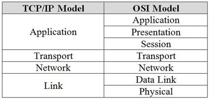
TCP/IP Model compared to the OSI Model
The layered approach to network communication has proven to be a reliable framework for creating a massive global network of networks (otherwise known as the Internet). The concept is something that was far ahead of its time when it was developed. We should be grateful for the contributions of everyone involved. Some of the key people responsible for developing or influencing packet switching and TCP/IP are listed below.
Inventors of packet switched networks: Donald Davies (United Kingdom) and Paul Baran (United States)
Researchers who pioneered concepts that lead to the creation of TCP/IP: Louis Pouzin (France) and Hubert Zimmermann (France)
Creators of TCP/IP: Vinton Gray Cerf (United States) and Robert Kahn (United States)
Networking pioneers (source: Wikipedia)
Society is indebted to these brilliant scientists, researchers, and engineers, plus many other unsung heroes for their contributions to networking.
Components of TCP/IP
Now that we have covered the history and fundamental architecture of the TCP/IP model, it’s time to dive into the key elements that make it work. The list below provides an overview of the core components of TCP/IP.
IP Addresses: A numerical (IPv4) or hexadecimal (IPv6) address assigned to a network device. The IP address identifies the system it is assigned to and allows it to be located on a local or wide area network.
Ports: A port is a numerical address assigned to an application or protocol on a networked system. The port number identifies the service or program running at the numbered location. There are 65,535 ports available for use. Common examples of ports are 25 for SMTP, 53 for DNS, and 80 for HTTP.
Note: More common port numbers will be discussed later in this chapter.
Protocols: A protocol is the defined syntax for communication between networked systems. Protocols operate at various levels of the TCP/IP model and when layered together allow dissimilar systems to speak a common language and communicate effectively. Common examples are TCP, UDP, HTTP, SMTP, and DNS.
Segments: A segment (also known as a datagram) is the first stage of dividing up data for transmission on a packet switched network. Segments are generated at the Transport layer of the TCP/IP and OSI (layer 4) models. The most common examples of transport layer protocols are TCP and UDP.
Packets: Packets are units of data that are transmitted and received on a network. A packet is the form of data used at the Internet layer of the TCP/IP model or the Network Layer (Layer 3) of the OSI model. Segments are turned into packets in preparation for transmission over a link.
Frames: A frame is the next unit of data below a packet. Packets are converted into frames as they are transmitted across a physical network connection. The frame itself is a collection of bits (discussed next).
Bits: Bits are the “ones and zeroes” of computing. Bits are binary values that are a digital representation of the data being transmitted electrically across a network link/interface.
These concepts combine to make up the core of modern networking systems. Applications use IP addresses to reference each other. Ports are established between IP addresses for utilizing protocols. Segments/datagrams are created from application data and turned into packets. Then, network interfaces turn packets into frames and bits. This process of layering protocols is known as encapsulation.
Information flows up and down the TCP/IP stack on each side of the connection at impressive rates. This cycle repeats many hundreds (or thousands) of times per second. The result is a marvel of engineering that allows computers to talk to each other.
Anatomy of Segments/Datagrams, Packets, and Frames
It’s fascinating to think about how information flows across packet switched networks. Everything is beautifully orchestrated using a collection of protocols. Data is broken down into tiny chunks, transmitted across a connection, and then reassembled on the receiving side. This is the miracle that allows us to watch cat videos online whenever we please.
When it comes to Nmap, IP packets and TCP/UDP segments and datagrams are the keys to how the scanner works its magic. The information gleaned from analyzing this data allows Nmap to determine if ports on a target system are open or closed. The incredibly clever Nmap developers have also figured out how to use this information to determine which application versions and underlying operating system are running on the target system. This makes Nmap a great tool for network analysis.
Since these components are central to how Nmap works, let’s delve a little deeper to understand how they are structured so we can better understand the program’s features.
TCP Segments and UDP Datagrams
TCP and UDP are the two most common transport protocols. TCP uses a robust packet structure to provide reliable delivery of data between hosts on a network. In contrast, UDP is a simpler protocol that is less reliable, but in turn requires less processing overhead. Packets for both protocols consist of a header along with payload data. The diagrams below illustrate the structure of each protocol’s PDU (Protocol Data Unit).
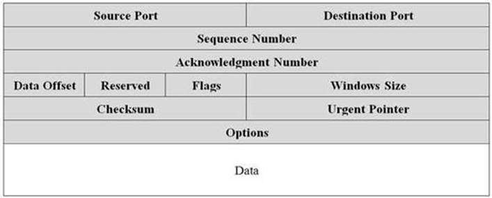
TCP segment PDU
Information in the TCP header is utilized to route the data stream to the proper port location in a reliable and ordered fashion. TCP uses sequences, acknowledgments, and windows to ensure proper delivery of data to the target system. This structure is what makes TCP considered a reliable “connection-oriented” transport protocol.
The information in the UDP header is much simpler. UDP does not provide guaranteed delivery, so less information is required in the datagram. This reduces overhead and latency at the expense of reliability, which makes UDP considered a “connectionless” transport protocol.
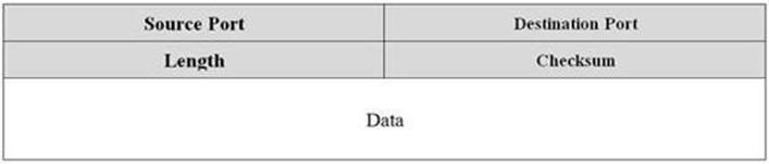
UDP datagram PDU
IP Packets
PDUs for TCP/UDP are encapsulated in IP packets for transmission on packet switched networks. The IP packet consists of a header and the TCP or UDP payload data. The following diagram describes the IP packet structure.
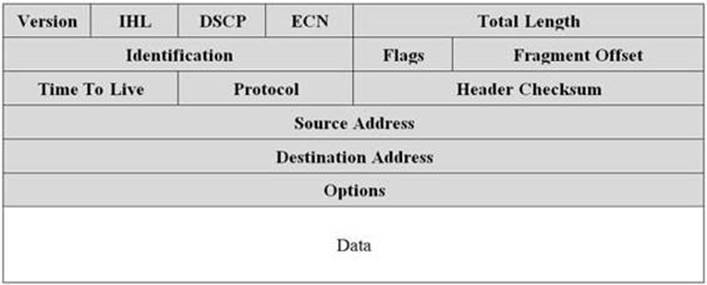
IP packet
The IP protocol analyzes the header in each packet to determine where it needs to be relayed to reach its final destination. Each IP packet header contains information about the source/destination addresses, type of protocol being used, packet size, and a number of optional flags. There are also a number of other fields that help ensure timely and reliable delivery to the destination address such as the checksum and TTL.
Ethernet Frames
When a packet is ready to be transmitted, it is converted into an Ethernet frame. The frame encapsulates the packet in a simple structure that has a header with addressing and signaling information plus a trailer that is used for error checking. The diagram below describes the ethernet frame structure.

Ethernet frame structure
Putting It All Together
When you stack everything together you get a nice sandwich of protocols that dictate how data flows across a network connection. The information in the protocol headers is utilized to facilitate the communication exchange at each step along the way. The result is reliable communication between hosts on a network.
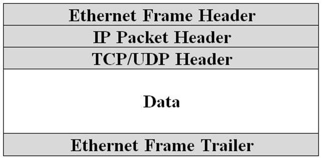
Encapsulation of network PDUs
The information in the protocol headers is the nuts and bolts that make TCP/IP function. Later in this guide, you will learn how Nmap can be used to control the fields in these headers when scanning. This will allow you to generate custom probes in an attempt to generate a response from a target system.
Common Application Protocols and Ports
TCP and UDP make use of 65,535 ports for network communication. Of these, only a handful are commonly used for hosting network application services. The list below describes some of the most well-known services along with their associated port numbers and transport protocols.
20 TCP
FTP Data
21 TCP
FTP Control
22 TCP|UDP
Secure Shell (SSH)
23 TCP
Telnet
25 TCP
Simple Mail Transfer Protocol (SMTP)
42 TCP|UDP
Windows Internet Name Service (WINS)
53 TCP|UDP
Domain Name System (DNS)
67 UDP
DHCP Server
68 UDP
DHCP Client
69 UDP
Trivial File Transfer Protocol (TFTP)
80 TCP|UDP
Hypertext Transfer Protocol (HTTP)
110 TCP
Post Office Protocol 3 (POP3)
119 TCP
Network News Transfer Protocol (NNTP)
123 UDP
Network Time Protocol (NTP)
135 TCP|UDP
Microsoft RPC
137 TCP|UDP
NetBIOS Name Service
138 TCP|UDP
NetBIOS Datagram Service
139 TCP|UDP
NetBIOS Session Service
143 TCP|UDP
Internet Message Access Protocol (IMAP)
161 TCP|UDP
Simple Network Management Protocol (SNMP)
162 TCP|UDP
Simple Network Management Protocol (SNMP) Trap
389 TCP|UDP
Lightweight Directory Access Protocol (LDAP)
443 TCP|UDP
Hypertext Transfer Protocol over TLS/SSL (HTTPS)
445 TCP
Server Message Block (SMB)
636 TCP|UDP
Lightweight Directory Access Protocol over TLS/SSL (LDAPS)
873 TCP
Remote File Synchronization Protocol (RSYNC)
993 TCP
Internet Message Access Protocol over SSL (IMAPS)
995 TCP
Post Office Protocol 3 over TLS/SSL (POP3S)
1433 TCP
Microsoft SQL Server Database
3306 TCP
MySQL Database
3389 TCP
Microsoft Terminal Server/Remote Desktop Protocol (RDP)
5800 TCP
Virtual Network Computing (VNC) web interface
5900 TCP
Virtual Network Computing (VNC) remote desktop
This is just a short list of some of the most common port numbers used on modern networks. Ports 0 through 1023 are reserved for "well-known services". These ports are central to common services associated with basic network functionality. Ports 1024 through 49151 are registered with the Internet Assigned Numbers Authority for use with vendor specific network based applications. Ports 49152 to 65535 are dynamic ports that are primarily used for outbound connections from client systems.
Tip: See the link below for a longer list of notable ports and their associated usage.
wikipedia.org/wiki/List_of_TCP_and_UDP_port_numbers