Mastering Autodesk Inventor 2015 and Autodesk Inventor LT 2015 (2014)
Chapter 20. iLogic
In this chapter, you will explore the use of iLogic to configure your models with intelligence and automation. iLogic is often used to speed up tedious design tasks, to enforce consistency across designs, and to allow the logic of programming to make design decisions based on predetermined design rules. Although this chapter focuses primarily on using iLogic in the parts environments, the fundamentals you'll learn will apply to the assembly and drawing environments as well.
In this chapter, you'll learn to
· Create iLogic rules
· Edit iLogic rules
· Use multi-value list parameters
· Work with multiple rules in the same file
· Use conditional statements
· Suppress features
· Work with iProperties
· Create iLogic forms
· Build a part configuration form
What Is iLogic?
iLogic is a programming add-in that is included with the Autodesk® Inventor® software. It extends and enhances the design capabilities and allows you to automate tedious design tasks. By creating custom iLogic code, you can add higher levels of design intelligence to your models. Using the iLogic tools, you can create simple, rule-based logic to set and drive parameters and properties in your designs. iLogic rules can be embedded directly into individual Inventor files, or they can be saved externally where they can be accessed by all of your Inventor files. iLogic uses custom parameter types to allow you to customize more than just the numeric data available with standard Inventor model parameters. These types include Text parameters, True/False parameters, and multi-value list parameters.
To understand how iLogic works, you need to think in terms of design rules. Most design departments already have certain design rules they follow when creating parts and assemblies. For instance, suppose a design requires a minimum hole spacing to ensure a strong connection. If a part length causes the spacing to exceed the minimum hole spacing, then another hole is added.
Currently, you might follow these rules manually as you design, but with the use of iLogic, you can add the rules to the model file so that the design rules are implemented automatically. You can even have rules trigger other rules so that a cascade of decisions is made based on initial input from the user.
Understanding iLogic Rules
An iLogic rule can be thought of as a small Visual Basic .NET “program” created and used to monitor and control Inventor objects such as parameters, features, and components. A rule can determine and/or set design parameters within your model. This allows you to control the values of the model automatically, based on conditions and inputs.
For example, you might have a product line offered to your customer in standard cataloged sizes, with standard features included or excluded based on the size and application. But you also offer this same design in custom sizes when needed. With traditional Inventor tools, you would determine whether the requested size is standard, and if it is not, you would create a new custom-size component to fit the need. Once the size is determined, you would decide to include or exclude features per your design guidelines and then include other features based on the specific application of this custom design.
Because the process of configuring your product line relies on your experience and memory, it might be time-consuming and error-prone, particularly if you need to have another Inventor user, with less experience with your product, create the design. You can use iLogic to set up a collection of rules in a template file. The first rule might allow you to input the requested size using a customized dialog form. Another rule would determine whether the requested size is an existing standard size or a new custom one. If it is a custom size, a part number and description are automatically generated to honor your standard nomenclature. Yet another rule would then determine whether standard features are included or excluded based on the size (for example, if the hole spacing exceeds X, add another hole). And finally, another rule might be invoked to add application-specific features (for example, add left-hand switch mounting holes, if the custom design is for a left-hand application).
What Are Functions?
A function is an instruction created and used within a rule to modify the Inventor model or read some data from the file. When a rule is run, the functions within it are executed. The predefined iLogic functions follow VB.NET syntax and require the coding to follow the syntax to work. This syntax consists of the function category, function name, and function arguments.
In the previous example, where the goal was to create a collection of rules to determine a standard or custom size, the first rule would control the dialog box to collect the input from the user. So, a function would be added to call an input box function and then assign the collected input to an Inventor parameter. Here is an example of an input box function used to prompt the user for a width value:
myWidth = InputBox("Please Enter A Width", "Width Input", "750")
The resulting input box displays as shown in Figure 20.1 and creates a return value called myWidth, which is set to the value the user enters into the input box. In this case, the default value has been set to 750. So if the user were to accept the default value by clicking the OK button, myWidth would be set to 750.
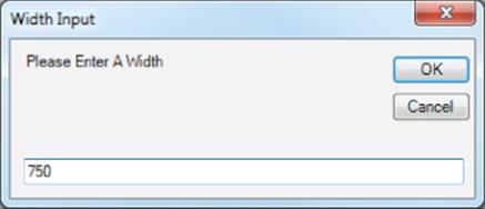
Figure 20.1 A basic iLogic input box
You might include multiple functions in the same rule, depending on its complexity. When doing so, you will typically place functions in order so that information is created or gathered from one function and then used later by another function. Typically, each function is independent of the remaining code in the rule.
To use the myWidth value from the previous example, you could create a second function to set the Inventor parameter controlling the width of the part equal to myWidth. Here, the Inventor parameter is a dimension in a sketch that has been named Wid1:
myWidth = InputBox("Please Enter A Width", "Width Input", "750")
Parameter("Wid1") = myWidth
There are several categories of functions provided in iLogic. You can find all of the available functions when creating rules by expanding the function category node in the rule editing interface. Here is the list of iLogic categories:
|
Parameter functions |
Variables functions |
|
Document functions |
iFeature functions |
|
Feature functions |
Material Properties functions |
|
Run Other functions |
Assembly Constraint functions |
|
Component functions |
Sheet Metal functions |
|
BOM functions |
Measure functions |
|
iProperties functions |
Drawing functions |
|
Math functions |
Work Feature functions |
|
Excel Data Links functions |
Advanced Drawing API functions |
|
String functions |
Message Box functions |
|
iPart and iAssembly functions |
Advanced API functions |
Working with Function Arguments and Data Types
Within functions, you can also have arguments. An argument is a value that is sent to the function when it is called. Passing an argument to a function gives the function information to work with. An argument can be one of the following data types:
1. Text Any value specified inside double quotes
2. Boolean A value of True or False
3. Numeric Any numeric value
Set Values with Functions
Take a look at this example to see the text string and Boolean data types in use:
Feature.IsActive("Hole1") = False
Here, the function category Feature is being used. The Feature function IsActive is instructed to look for the feature called Hole1, and then the False argument tells the function to suppress Hole1. If the Boolean were set to True, then the hole would be set active or not suppressed. You'll notice Hole1 is set inside double quotes, thereby specifying it as a text string.
Next, look at this example to see numeric data in use:
Parameter("Diameter1") = 4.4
Here, the Parameter function is being told to look for the feature called Diameter1 and then use 4.4 as the value. In both of these examples, the function is setting a value. In addition to setting values, you can retrieve or get values using functions.
Get Values with Functions
In the following examples, you'll look at how to get a value from a function. You'll start off with the reciprocal function for the previous function involving Diameter1:
Current_Dia = Parameter("Diameter1")
Here, the Parameter function is being told to create a return value placeholder called Current_Dia and then set it to the parameter called Diameter1. Next, look at an input box function:
Wid1 = InputBox("Please Enter A Width", "Width Input", Wid1)
In this function, the return value happens to be an Inventor dimension parameter named Wid1, which is a sketch dimension defining the width of the part. The input box reads the Wid1 parameter into the default value (on the far right) so that the user is presented with the current width and at the same time is prompted to enter a new value. When the user clicks the OK button, the input box value is written to the Inventor dimension parameter named Wid1.
Here is an example comparing the use of functions to get and set information:
iProperties.Value("Project", "Revision Number") = 2
RevNumber = iProperties.Value("Project", "Revision Number")
In the first line, the function is being given the arguments Project and Revision Number to specify that iProperty be set to 2. In the second line, the return value called RevNumber is being set to the current Revision Number iProperty for the file. Again, it uses the argumentsProject and Revision Number to tell the iProperty collection which iProperty to read.
Conditional Statements
You use conditional statements to put the logic in iLogic. The conditional statements evaluate the present state of the model and execute logic depending upon that state. For example, if the hole spacing in a part exceeds a minimum value because of a change in length, then another set of holes is required:
Space1 = Parameter("Hole_Space")
If Space1 >=45 Then
Feature.IsActive("Hole2") = True
Else
Feature.IsActive("Hole2") = False
End If
In the first line, a return value parameter named Space1 is set to the model parameter called Hole_Space. Then, Space1 is evaluated to determine whether it is less than or equal to 45. If so, it is set to be active (not suppressed). Otherwise, it is suppressed. The following sections include examples of each of the available conditional statements.
If, Then, Else Statement
If, Then, Else is probably the most common of the conditional statements. It tests for a condition and then applies one or more actions if the condition is found to be true; otherwise, it applies one or more other actions:
If <condition> Then
<action if true>
Else
<action if false>
End If
If, Then Statement
If, Then tests for a condition and then applies one or more actions if the condition is found to be true. If the condition is not true, then nothing happens.
If <condition> Then
<action if true>
End If
What Are Comments?
Text preceded by an apostrophe in iLogic is interpreted as a comment and not as code. You can use this to your advantage by adding notes to your iLogic code to make it easier to understand.
Null Statement
A null If, Then tests for a condition and then applies no action if the condition is found to be true (the 'do nothing in the following statement is simply a comment and could be omitted). If the condition is not true, one or more actions are applied:
If <condition> Then 'do nothing
Else <action if false>
End If
Single-Line If Statement
You can use a single-line If statement when testing a simple, short condition with short true and false statements. Single-line If, Then tests for a condition and then applies one or more actions if the condition is found to be true. If the condition is not true, then nothing happens:
If <condition> Then <action if true> Else <action if false>
If, Then, ElseIf Statement
Using the If, Then, ElseIf format, you can add as many conditions as you want. Here is the format when three conditions are being tested. If, Then, ElseIf tests for a condition and then applies one or more actions if the condition is found to be true. If not true, it tests another condition, and so on. If none of the tested conditions is found to be true, it applies one or more other actions. If no final action is specified, nothing happens unless one of the conditions is found to be true:
If <condition 1> Then
<action if condition 1 is true>
ElseIf <condition 2> Then
<action if condition 2 is true>
ElseIf <condition 3> Then
<action if condition 3 is true>
Else
<action if none of the above conditions is true>
End If
Select Case Statement
The Select Case statement is another way to test what is inside a variable. You can use it when you know there are only a limited number of values that the variable could hold:
Select Case <test expression>
Case <expression list 1>
<statement list 1>
Case <expression list 2>
<statement list 2>
Case Else
<statement list n>
End Select
For instance, if a multi-value list parameter named Part_Size consisted of a list containing Small, Medium, and Large, you could set the test expression to Part_Size and set up three cases called Small, Medium, and Large, as shown here:
Select Case Part_Size
Case "Small"
Len = 50
Wid = 40
Case "Medium"
Len = 75
Wid = 65
Case "Large"
Len = 100
Wid = 90
End Select
When the Part_Size parameter is set to Small, the case named Small is selected, and the Len and Wid parameters are set to the values corresponding to the small size.
Understanding the iLogic Elements and Interface
There are two primary areas within Inventor used to create and manage iLogic rules: the Parameters editing dialog box and the iLogic browser. The Parameters dialog box is used to create and edit parameters to be used in iLogic, and the iLogic browser allows you to create and manage rules. Figure 20.2 shows the Parameters button, accessed from the Manage tab, and Figure 20.3 shows the iLogic Browser button, also accessed from the Manage tab.
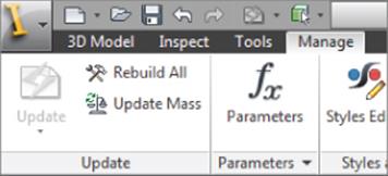
Figure 20.2 The Parameters button
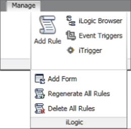
Figure 20.3 The iLogic Browser button
Exploring iLogic Parameter Types
Recall that Inventor has three types of parameters:
· Model parameters are created by dimensions and feature inputs.
· Reference parameters are created from driven dimensions.
· User parameters are created by you, the user.
Within the user parameter category, you can create three parameter types: the Text parameter, the True/False parameter, and the Numeric parameter. The Numeric parameter can be referenced into your Inventor model using the standard Inventor tools, but the Text and Boolean parameters can be used only with the iLogic tools.
To create user parameters and specify the type, you use the drop-down list in the Parameters dialog box, as shown in Figure 20.4.
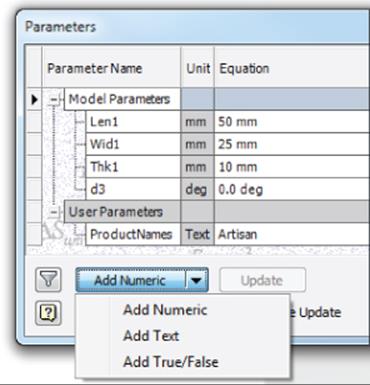
Figure 20.4 User parameter types
Text Parameters
A Text parameter is any value specified within double quotes. For instance, if you wanted to use product names in an iLogic rule to fill out iProperty information, you could create a Text parameter to contain that information. Keep in mind that you can create a Text parameter using numeric data by enclosing it in double quotes. For instance, Inventor will read “22 mm” as a text string but 22 mm as numeric data. Text parameters can be set to be multi-value list parameters or used as static, single-value parameters.
True/False Parameters
True/False parameters fall within the Boolean data type. They have only two states: True and False. A True/False parameter would be used, for example, when asking a user a question. Figure 20.5 shows an input box with two radio buttons. Depending on which the user chooses, a True/False parameter named Part_Type is toggled.
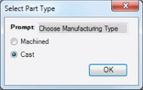
Figure 20.5 An input box used to toggle a True/False parameter
Here is the iLogic rule that produces the input box and then sets the True/False parameter named Part_Type. The Part_Type parameter is then used to set the material iProperty of the part file:
Part_Type = InputRadioBox("Choose Manufacturing Type", "Machined", "Cast", _
Part_Type, Title:= "Select Part Type")
If Part_Type = True Then
iProperties.Material = "Aluminum-6061"
ElseIf Part_Type = False Then
iProperties.Material = "Cast Steel"
End If
Numeric Parameters
Numeric parameters are the parameters used by Inventor sketch dimensions and feature dialog box inputs. When you create a sketch dimension and input value, you are creating a Numeric parameter. You can create Numeric user parameters to hold formulas, which are then called into sketch dimensions, and so on. In addition to using Numeric parameters with the standard Inventor modeling tools, you can use them with iLogic. Numeric parameters can be set to be multi-value list parameters or used as static, single-value parameters.
Note that you can add unit strings to Numeric parameters and Inventor will still read them as numeric. For instance, Inventor will read 45 mm as numeric data. If the model length unit is set to millimeters, Inventor will read 45 as numeric data and assume millimeters. Recall that you can set the default units for any model file by selecting the Tools tab, clicking the Document Settings button, and then selecting the Units tab.
Multi-Value Lists
Text and Numeric parameters can consist of a single, static value or can be made into a multi-value list. To create a multi-value list, follow these general steps:
1. On the Manage tab, click the Parameters button.
2. In the Parameters dialog box, choose Add Text or Add Numeric from the drop-down at the bottom left.
3. Name the Text parameter as you see fit (recall that spaces are not allowed in parameter names, but you can use an underscore).
4. Right-click the new parameter and choose Make Multi-Value.
5. Enter values into the list editor to populate your list.
Figure 20.6 shows a multi-value list for product names being populated. The values on the bottom have already been added; the ones on the top are being entered.
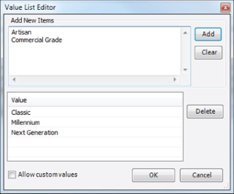
Figure 20.6 Populating a multi-value list
Once the multi-value list is populated, you can add or remove entries by right-clicking the parameter and choosing Edit Multi-Value List, as shown in Figure 20.7.
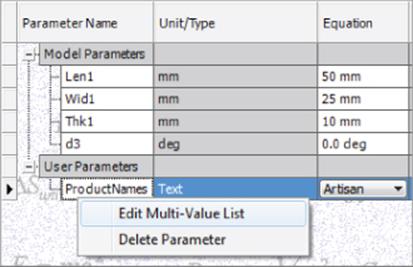
Figure 20.7 Editing a multi-value list
Key Parameters
You can designate some parameters as Key parameters to aid in the placement of iLogic components into an assembly later. For instance, if you had a part file with 50 parameters in it, you'd likely want to designate only a small number of those as key parameters. This allows you to choose which parameters the user can adjust during the file placement, and it streamlines the process as well. To set a parameter to be a key, click the Filter button at the lower left of the Parameters dialog box.
Using the iLogic Browser
The iLogic browser is the interface item used to create, edit, and manage rules and forms within Inventor. You can access the iLogic browser from the Manage tab by clicking the iLogic Browser button on the iLogic panel, as shown previously in Figure 20.3. Once it's displayed, you will find four tabs in the iLogic browser:
· Rules
· Forms
· Global Forms
· External Rules
The Rules Tab
The Rules tab allows you to add, edit, run, regenerate, suppress, and delete rules. When rules are created, they are automatically listed in the Rules tab; therefore, the Rules tab will always list all rules embedded in the current document.
Adding Rules
To add a new rule to an Inventor file, right-click anywhere in the Rules tab of the iLogic browser and choose Add Rule (Figure 20.8).
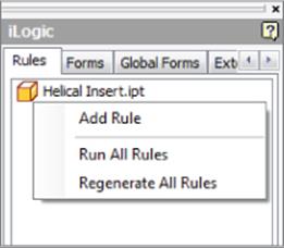
Figure 20.8 Choose Add Rule from the browser to begin creating an iLogic rule
Alternatively, you can use the Add Rule button on the iLogic panel of the Manage tab. The first step to adding a rule is entering a name for the rule in the Rule Name input box. Once the name is entered, you are presented with the Edit Rule dialog box, where you can build the rule. You'll explore the creation of rules in the coming pages.
Editing Rules
To edit an existing rule in an Inventor file, right-click the rule in the Rules tab of the iLogic browser and choose Edit Rule (Figure 20.9). You will be presented with the Edit Rule dialog box, where you can make changes to the rule. The section “Creating iLogic Rules” later in the chapter shows how to build rules in this dialog box.
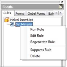
Figure 20.9 Choosing to edit an iLogic rule from the browser
The Forms Tab
The Forms tab allows you to add iLogic user input forms. These forms are built using the iLogic Form Editor, which makes creating customized user input forms remarkably easy. You'll work with the Form Editor in “Creating iLogic Forms.”
Adding Forms
To add a new form to an Inventor file, select the Forms tab in the iLogic browser, right-click in the tab, and choose Add Form (Figure 20.10).
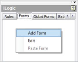
Figure 20.10 Choosing to add an iLogic form from the browser
You can also add forms by selecting the Manage tab, clicking the drop-down found on the iLogic panel, and then clicking the Add Form button. When using this method, you'll have an option to choose whether the form is intended to be embedded in the current document or to be a global form used by all documents.
Editing Forms
To edit an existing form in an Inventor file, right-click the Form button in the Form tab and choose Edit (Figure 20.11).
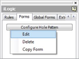
Figure 20.11 Choosing to edit an iLogic form from the browser
The Global Forms Tab
The Global Forms tab lists all the rules stored outside of Inventor, independent of the actual Inventor file you are working on. Global forms can be used when you want to use the same form across multiple rules so that you don't need to create the form over and over again. They also help promote consistency, and you can make edits to forms in multiple rules quickly and in one global location. To add a global form, you set the Global Forms tab to active, right-click in the tab, and choose Add Form (Figure 20.12).
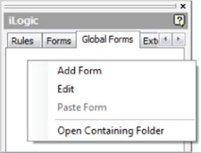
Figure 20.12 Choosing to add a global iLogic form from the browser
You can also add global forms by selecting the Manage tab, clicking the drop-down on the iLogic panel, and then clicking the Add Form button. When using this method, you have an option to embed the form in the current document or use it as a global form in all documents.
Global forms are stored within the Design Data folder. You can find the location by clicking the Global Forms tab and choosing Open Containing Folder (shown in Figure 20.12). Recall from Chapter 1, “Getting Started,” that the location of the Design Data folder can be specified in two ways:
1. Application Options On the Tools tab, click the Application Options button and then click the File tab. Set the Design Data path to the location of your choice. Be aware that this sets the location on the installation of Inventor being used to set the path. Therefore, if you work with other Inventor users and want to have all of the installs looking at the same Design Data folder, you would need to walk around to each machine and set this path or use the Project Settings method.
2. Project Settings Close all open Inventor files. Ensure that no other users are accessing the project file (*.ipj) that you intend to edit. On the Get Started tab, click the Projects button. In the Projects editor dialog, locate the Folder Options node in the bottom pane and expand it. Set the Design Data path to the location of your choice. This method sets the path per the project file and therefore overrides the Application Options setting if the two do not match. If multiple users are using the same project, then all of them will now be using the new Design Data folder.
The External Rules Tab
The External Rules tab lists all the rules stored outside of Inventor, independent of the actual Inventor file you are working on. External rules can be used as iLogic rules or as small programs that are run manually (like VBA macros). To add an existing external rule, set the External Rules tab active, right-click in the tab, and choose Add External Rule, as shown in Figure 20.13.
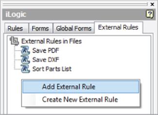
Figure 20.13 Adding an external rule from the browser
When you choose Create New External Rule, you will be prompted with the Create Rule File dialog box, where you can browse to a location and save the rule as one of the three available file formats: plain text (*.txt), iLogic VB (*.ilogicVb), or Visual Basic (*.vb). Generally, this location is on a shared network where all users can access the files. Figure 20.14 shows a new external rule being created and saved in a location called iLogic Rules in the Mastering Inventor project path. Once the rule file is created, you are presented with the Edit Rule dialog box, where you can build the rule. External rules are often used with event triggers, such as Before Save, which will run the rule when the file is saved.
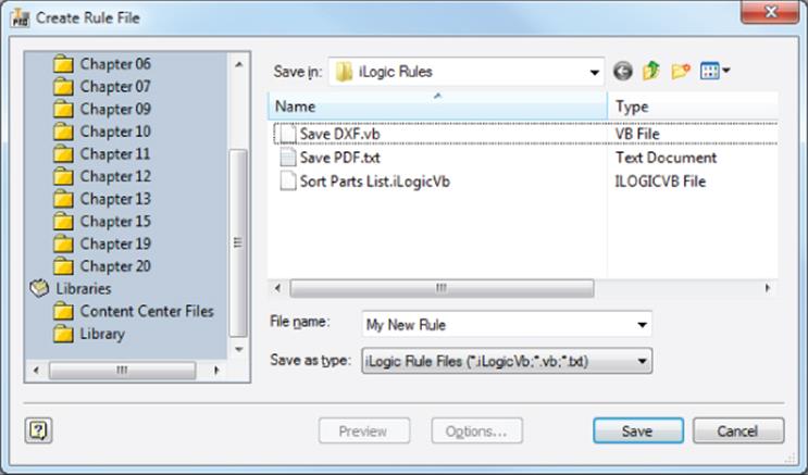
Figure 20.14 Creating an external rule
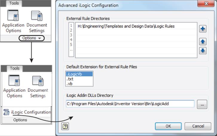
External Rule File Save Location
You can set up default external rule file save locations and the default filename extension by selecting the Tools tab, clicking the drop-down on the Options panel, and then clicking the iLogic Configuration button, as shown here.
Understanding the iTrigger
An iTrigger is an Inventor user parameter that you can include in the current file to trigger rules manually. This parameter is often used to test a rule while you are creating it. The iTrigger parameter may not be as useful as it was before the iLogic browser made the rules more easily accessed.
The iTrigger button on the iLogic panel of the Manage tab initially creates a user parameter named iTrigger0. If the parameter already exists, the value of the iTrigger parameter is incremented by 1 and triggers any rule containing the iTrigger0 parameter. If multiple rules contain the iTrigger, they are all triggered. Here is a rule to save the current file as a PDF that contains the iTrigger:
'set the trigger
trigger = iTrigger0
'path and file name without extension
path_and_name = ThisDoc.PathAndFileName(False)
'call the PDF addin
PDFAddIn = ThisApplication.ApplicationAddIns.ItemById_
("{0AC6FD96–2F4D-42CE-8BE0–8AEA580399E4}")
oDocument = ThisApplication.ActiveDocument
oContext = ThisApplication.TransientObjects.CreateTranslationContext
oContext.Type = IOMechanismEnum.kFileBrowseIOMechanism
oOptions = ThisApplication.TransientObjects.CreateNameValueMap
oDataMedium = ThisApplication.TransientObjects.CreateDataMedium
'set the PDF publish options
If PDFAddIn.HasSaveCopyAsOptions(oDataMedium, oContext, oOptions) Then
'oOptions.Value("All_Color_AS_Black") = 0
oOptions.Value("Remove_Line_Weights") = 1
oOptions.Value("Vector_Resolution") = 400
oOptions.Value("Sheet_Range") = Inventor.PrintRangeEnum.kPrintAllSheets
'oOptions.Value("Custom_Begin_Sheet") = 2
'oOptions.Value("Custom_End_Sheet") = 4
End If
'Set the destination file name
oDataMedium.FileName = path_and_name & ".pdf"
'Publish PDF
.Call PDFAddIn.SaveCopyAs(oDocument, oContext, oOptions, oDataMedium)
Working with Event Triggers
An event trigger is used to set up a rule to trigger automatically. For instance, you might want to create a rule to prompt you to fill out the file properties when you save the file. To do so, you simply add the rule to the Before Save event. The rule is triggered when you save a file, allowing you to enter or confirm the iProperties, and then the file is saved. Here is a list of the available event triggers:
· When a new file is created
· After a file is opened
· Before a file is saved
· After a file is saved
· Before a file is closed
· When any model parameter is changed
· When an iProperty is changed
· When a feature of a part is suppressed or unsuppressed
· When the geometry of a part is changed
· When the material of a part is changed
· When a component of an assembly is suppressed or unsuppressed
· When a component of an iPart or iAssembly is changed
· When a drawing view is changed
To add a rule to an event trigger, select the Manage tab, and click the Event Trigger button on the iLogic panel. Then select the event you want to use and click the Select Rules button. You can then select from the available rules. Keep in mind that you will see only applicable event triggers in the list when setting a trigger for an event. For instance, if the current file you are working in is an IDW file, you will not see event triggers such as Material Change (changing the material of a part) in the list.
Creating iLogic Parameters, Rules, and Forms
Now that you've had an overview of the iLogic tools and components, you are ready to create iLogic parameters, rules, and forms. You'll start by focusing on rules using input and message boxes and then look at creating and using iLogic forms.
Creating iLogic Rules
In the following pages, you'll explore the methods and options of creating iLogic rules. To add a new rule to an Inventor file, you right-click the file node in the Rules tab of the iLogic browser and choose Add Rule.
Creating Your First Rule
Once a rule is created using Add Rule, you are presented with the Edit Rule dialog box. This dialog has four main interface panes, as shown in Figure 20.15:
1. Function Category List (#1) Contains all of the iLogic function categories for easy access and reference.
2. Rule Authoring Pane (#2) The area where you input and edit your rule code.
3. Tabs Area (#3) Provides access to the Model, Options, Search And Replace, and Wizards tools. In Figure 20.15, the Model tab is selected. You can see that it gives you access to the model parameters and features for inclusion in the rule.
4. Subtabs (#4) A subset of the Model tab. As displayed in Figure 20.15, the Parameters tab lists the model parameters because Model Parameters is selected on the left.
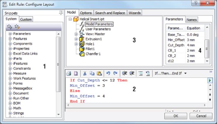
Figure 20.15 The Edit Rule dialog box
To see how all of this works, you can use the following steps to create a simple rule. If you have not already downloaded the Chapter 20 files from www.sybex.com/go/masteringinventor2015, please refer to the “What You Will Need” section of the introduction for the download and setup instructions. The goal of the rule you will create in this example is to create user inputs to control the width and length of the plate:
1. Click the Open button on the Get Started tab, browse for mi_20a_001.ipt in the Chapter 20 directory of your Mastering Inventor 2015 folder, and open it.
2. Click the Manage tab and select the iLogic Browser button on the iLogic panel to ensure your iLogic browser is displayed.
3. In the iLogic browser, ensure that the Rules tab is selected, right-click anywhere in the Rules tab, and choose Add Rule or click the Add Rule button on the iLogic panel of the Manage tab in the ribbon.
4. Enter Size Input into the Rule Name dialog box and then click the OK button.
5. In the Edit Rule dialog box, make sure the Model tab along the top is set active and then expand the model node (if needed) and select Model Parameters. All of the model parameters for this part file are now listed in the Parameters subtab on the right.
6. In the Model tab, click Extrusion1 and notice the Parameters tab now shows only the parameters used in Extrusion1.
7. In the Function Category list (on the left), locate the MessageBox node and expand it by clicking the plus sign.
8. Locate the InputBox item toward the bottom of the list and double-click it. This will place the generic InputBox function into your rule, thereby providing the template syntax you need to follow. This function should read as follows:
myparam = InputBox("Prompt", "Title", "Default Entry")
· myparam is the placeholder for the return value (the value retrieved from the input box).
· InputBox is the name of the function.
· “Prompt” is the placeholder for the message to appear in the box.
· “Title” is the placeholder for the text to appear in the title bar of the box.
· “Default Entry” is the placeholder for the text to display in the input field of the box when it is first opened.
Function Syntax Guide
If you look in the help files under User's Guide ![]() iLogic
iLogic ![]() Functions and then refer to the Quick References tab, you can find a listing of all the functions with a guide and example of each one's syntax.
Functions and then refer to the Quick References tab, you can find a listing of all the functions with a guide and example of each one's syntax.
9. Select myparam in the Rule Authoring pane and then double-click Width in the Parameters subtab. This will replace myparam with the word Width.
Note that the color coding indicates that Width is a recognized parameter. You could have just deleted the word myparam and then typed in the word Width as well. If you had done so and accidentally typed width with no uppercase W, the word would not have turned blue to indicate a recognized parameter.
10.Delete the word Prompt and replace it with “Enter Width” (with the quotation marks).
11.Delete the word Title and replace it with “Width Input” (with the quotation marks).
12.Replace the words Default Entry with 100 mm (no quotation marks).
Your result should read as follows:
Width = InputBox("Enter Width", "Width Input", 100 mm)
13.Click the OK button to close the Edit Rule dialog and test the rule. You should be prompted with an input box that looks like the one in Figure 20.16.
14.Enter 150 in the input box and then click the OK button.
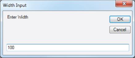
Figure 20.16 The width input box
You'll notice that the model width did not change as you might have expected. This is because the input box has changed only the Width parameter, and now the file needs to be updated. You should see that the Update button is active, indicating the model needs to be updated. You can click the Update button to see the model width change to 150 mm. In the next section, you'll edit a rule to make the model automatically update when the rule is run.
You can right-click the rule and choose Run Rule in order to test it and change the width value again. When you have finished, you can close the file without saving changes.
Editing Your Rule
In this exercise, you'll pick up where you left off and edit the Size Input rule you created in the previous exercise:
1. Click the Open button on the Get Started tab, browse for mi_20a_002.ipt in the Chapter 20 directory of your Mastering Inventor 2015 folder, and open it.
2. From the iLogic browser, locate the Size Input rule on the Rules tab and then right-click it and choose Edit Rule.
3. Place your cursor at the end of the existing function and press the Enter key on the keyboard a couple of times to provide some space in the rule.
4. In the Function Category list (on the left), locate the Document node and expand it by clicking the plus sign.
5. Locate the UpdateWhenDone item toward the middle of the list and double-click it. This will place the UpdateWhenDone function into your rule so that it looks like this:
6. Width = InputBox("Enter Width", "Width Input", 100 mm)
iLogicVb.UpdateWhenDone = True
7. Click the OK button to test the rule.
8. Enter 190 in the input box and click the OK button. Your part width should automatically change to 190 mm.
9. From the iLogic browser, right-click the Size Input rule and choose Edit Rule again.
Currently, your rule is coded to set the default entry of the input box to 100 mm. If you built this plate with a standard size of 100 mm for the width most of the time, then hard-coding that value might be the way to go. But often, it's more useful to retrieve the current parameter value and have it display in the input so the user knows the value before changing it.
10.Replace the 100 mm with Width. You can do this by typing over the value or by selecting it and then clicking Extrusion1 in the Model tab along the top. Then double-click the Width parameter to “push” it into the Rule Authoring pane. In either case, your function should look like this:
Width = InputBox("Enter Width", "Width Input", Width)
11.Click the OK button to test the rule and notice that the current width value of the model is listed in the input box. Replace this with 165 and click the OK button.
To finish this rule, you will add another function to change the length of the part. Follow the steps you used to create the width function so that your rule reads as follows and then test the part to see how it works:
Width = InputBox("Enter Width", "Width Input", Width)
Length = InputBox("Enter Length", "Length Input", Length)
iLogicVb.UpdateWhenDone = True
You can right-click the rule and choose Run Rule in order to test it and see how it functions. When you have finished, you can close the file without saving changes.
Creating a Rule Using a Multi-Value Parameter
In the previous exercises, you used an input box to change parameter values so that you could adjust the dimensions of the plate part. In this exercise, you'll create a multi-value parameter and then create a rule to get the user to select from the list. Follow these steps:
1. Click the Open button on the Get Started tab, browse for mi_20a_003.ipt in the Chapter 20 directory of your Mastering Inventor 2015 folder, and open it.
2. From the Manage tab, click the Parameters button.
3. Right-click the Length parameter and choose Make Multi-Value.
4. In the Value List Editor dialog box, enter the following values into the top pane and then click Add. If 175 mm is listed in the bottom pane, select it and click Delete to remove it.
· 150
· 160
· 170
· 180
· 190
5. Click the OK button to close the Value List Editor dialog box and then click Done to close the Parameters dialog box.
6. From the iLogic browser, ensure that the Rules tab is selected; then right-click anywhere in the Rules tab, and choose Add Rule.
7. Enter Size List Input into the Rule Name dialog box and click the OK button.
8. In the Edit Rule dialog box, make sure the Model tab along the top is set active and then expand the model node (if needed) and select Model Parameters. All of the model parameters for this part file are now listed in the Parameters subtab on the right.
9. In the Model tab, click Extrusion1 to show the parameters used in Extrusion1.
10.In the Function Category list (on the left), locate the MessageBox node and expand it by clicking the plus sign.
11.Locate the InputListBox item toward the bottom of the list and double-click it. This will place the generic InputListBox function into your rule, thereby providing the template syntax you need to follow. This function should look similar to this:
12. d0 = InputListBox("Prompt", MultiValue.List("d0"), d0, _
Title:= "Title", ListName:= "List")
· d0 is the placeholder for the return value (the value retrieved from the input box).
· InputListBox is the name of the function.
· “Prompt” is the placeholder for the message to appear in the box.
· MultiValue.List(“d0”) is the subfunction and the name of the multi-value list to use.
· d0 is the placeholder for the default list value to select in the input list of the box when it is first opened.
· The space and underscore that appear in this text break the line and allow it to wrap to the next line; however, you will not see this in your rule by default.
· “Title” is the placeholder for the text to appear in the title bar of the box.
· “List” is the placeholder for the text to appear above the list in the box.
13.Select d0 in the Rule Authoring pane and then double-click Length in the Parameters subtab. This will replace d0 with the word Length (no quotation marks).
When to Use Quotation Marks
Quotation marks indicate a text string. When you want the function to see your entry as a text string, use quotation marks. When you want the function to read a parameter (either from the model or from the rule), don't use quotation marks.
14.Delete the word Prompt and replace it with “Select Length” (with the quotation marks).
15.Replace d0 in MultiValue.List(“d0”) with “Length” (with the quotation marks).
16.Replace the next instance of d0 with 150 (no quotation marks). In this case, you want the input box to have a hard-coded default of 150.
17.Delete the word Title and replace it with “Length Selector” (with the quotation marks).
18.Replace the word List with “Available Standard Lengths” (with the quotation marks).
19.To make your code more readable in the editor, add an underscore after the comma following MultiValue.List(“Length”) and then press Enter on the keyboard. The underscore must have a space in front of it. This acts as a carriage return within the code, allowing the line to fit on-screen without upsetting the syntax.
Once the edits are made, your result should read as follows:
Length = InputListBox("Select Length", MultiValue.List("Length"), _
150, Title:= "Length Selector", ListName:= "Available Standard Lengths")
20.Click the OK button to exit the Edit Rule dialog and run the rule.
21.Click the Update button to see the model update.
To finish this rule, you will edit the Width parameter and make it a multi-value parameter with the same values you used for the length. Then, edit the rule and add another input list box function to change the width of the part. Follow the steps you used to create the length function. Then, add the function to make the part update when the rule is finished running (recall that you'll find this in the Document function category list) so that your rule reads as follows:
Length = InputListBox("Select Length", MultiValue.List("Length"), _
150, Title:= "Length Selector", ListName:= "Available Standard Lengths")
Width = InputListBox("Select Width", MultiValue.List("Width"), _
150, Title:= "Width Selector", ListName:= "Available Standard Widths")
iLogicVb.UpdateWhenDone = True
Finally, test the part to see how it works. When you have finished, you can close the file without saving changes.
Working with Multiple Rules in the Same File
In the next exercises, you'll work with both of the rules you created in the previous exercises and then create a third rule to choose which of the other two to run. Follow these steps to work with multiple rules in the same file:
1. Click the Open button on the Get Started tab, browse for mi_20a_004.ipt in the Chapter 20 directory of your Mastering Inventor 2015 folder, and open it.
2. From the iLogic browser, locate the Size Input rule on the Rules tab; then right-click it and choose Run Rule.
3. Enter 150 for Length and click the OK button.
4. Enter 150 for Width and click the OK button.
You'll notice that the Size List Input rule is run automatically when you click the OK button, presenting you with the Length Selector list input box.
5. Click the OK button in both the Length Selector and Width Selector input boxes.
The issue here is caused by both rules handling the same parameters. Currently, any change to those parameters causes the rules to run automatically. Although this might be the desired result in some cases, in this instance it is causing a problem. To resolve this, you will edit both rules and change their options.
6. From the iLogic browser, locate the Size Input rule on the Rules tab; then right-click it and choose Edit Rule.
7. Along the top, select the Options tab and select the Don't Run Automatically option, as shown in Figure 20.17; then click the OK button to exit the Edit Rule dialog box.
8. Click the OK button in the Length Input and Width Input boxes to accept the default values.
Next, you'll do the same thing for the Size List Input box.
9. From the iLogic browser, locate the Size List Input rule on the Rules tab; then right-click it and choose Edit Rule.
10.Along the top, select the Options tab, select the Don't Run Automatically option, and then click the OK button to exit the Edit Rule dialog box.
11.Click the OK button in the Length Selector and Width Selector boxes to accept the default values.
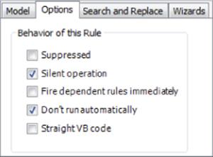
Figure 20.17 Rule options
As a test to see that the issue is resolved, you can run the rules and change the width and length values to ensure that neither rule runs when the other makes a change. Once you've tested this, you can close the file without saving and continue.

Handling Errors
Often, your rules will work fine when you test them because you enter expected results. But you can rest assured that as soon as you have other people test your rules, they'll encounter errors when they provide invalid input, for example.
Depending on the complexity of your code, you can often add a simple error handler to manage null inputs and other issues created when the user doesn't provide predictable or desired input.
You can use a simple On Error Resume Next line to skip or ignore an error. Although this is not considered a good practice for programming, it will often suffice for simple errors. For example, you can open the file mi_20a_022.ipt and run Rule0. If you click the Cancel button in the input box, you'll receive an error because the rule returns an empty string value. If you do the same for Rule1, the error is skipped because Rule1 includes an On Error Resume Next line.
Rule2 includes an On Error Goto ErrorHandler line that instructs Inventor to skip to the ErrorHandler line and display a message if an error is encountered. You can run Rule2 and click the Cancel button in the input box to see how this works. Rule3 checks for the specific problem of an empty text string and provides the user with a message. Rule4 does the same but just uses the existing value rather than the null input.
You can search online for VB error checking to find many more error-checking strategies.
Use a Conditional Statement to Run Another Rule
Next, your goal is to create a new rule to choose between two existing rules. But before doing so, you'll add a True/False user parameter and then edit the existing rule names to make them a bit more meaningful for your next task:
1. Click the Open button on the Get Started tab, browse for mi_20a_005.ipt in the Chapter 20 directory of your Mastering Inventor 2015 folder, and open it.
2. From the Manage tab, click the Parameters button.
3. From the lower-left corner, select the user parameter drop-down list (it shows Add Numeric by default).
4. Set it to Add True/False and then Enter Standard_Size for the parameter name.
5. Click Done to exit the Parameters dialog box.
Next, you'll rename the existing rules.
6. From the iLogic browser, locate the Size Input rule on the Rules tab, click it once to select it, and then slowly click it again to set the name active for renaming.
7. Enter Custom Size Input for the new name.
8. Repeat this for the Size List Input rule and rename it Standard Size List Input.
9. In the iLogic browser, right-click anywhere in the Rules tab, and choose Add Rule (note that you can also click anywhere in the blank space of the iLogic browser with the Rules tab active to add a rule).
10.Enter Size Type Input into the Rule Name dialog box and then click the OK button.
11.In the Function Category list (on the left), locate the MessageBox node and expand it by clicking the plus sign.
12.Locate the InputRadioBox item toward the bottom of the list and double-click it. This will place the generic InputRadioBox function into your rule, thereby providing the template syntax you need to follow. This function should read as follows:
booleanParam = InputRadioBox("Prompt", "Button1 Label", "Button2 Label", booleanParam, Title:= "Title")
· booleanParam is the placeholder for the return value (the value retrieved from the input box).
· InputRadioBox is the name of the function.
· “Prompt” is the placeholder for the message to appear in the box.
· “Button1 Label” and “Button2 Label” are the labels for the radio buttons.
· booleanParam is the placeholder for the default radio button to select when the input box is first opened.
· “Title” is the placeholder for the text to appear in the title bar of the box.
13.Make sure the Model tab along the top is set active and then expand the model node (if needed) and select User Parameters. All of the user parameters for this part file are now listed in the Parameters subtab on the right. In this case, there is just the one you created.
14.Select booleanParam in the Rule Authoring pane and then double-click Standard_Size in the Parameters subtab. This will replace booleanParam with Standard_Size (no quotation marks).
15.Delete the word Prompt and replace it with “Select Size Type” (with the quotation marks).
16.Replace Button1Label with “Standard Sizes” (with the quotation marks).
17.Replace Button2Label with “Custom Size” (with the quotation marks).
18.Replace booleanParam with True (no quotation marks). This sets the default to be true, which will be the first button, or the standard size option.
19.Delete the second instance of the word Title and replace it with “Standard or Custom” (with the quotation marks).
20. To make your code more readable in the editor, add an underscore after the comma following “Select Size Type” and then press Enter on the keyboard. The underscore must have space in front of it. This acts as a carriage return within the code, allowing the line to fit on-screen without upsetting the syntax.
Once the edits are made, your result should read as follows:
Standard_Size = InputRadioBox("Select Size Type", _
"Standard Sizes", "Custom Size", True, Title:= "Standard or Custom")
Currently, this rule doesn't do anything other than display an input box to let you choose between two buttons. To make those buttons do something meaningful, you will add a conditional statement to run one of the other existing rules.
21.From the toolbar along the top of the Rule Authoring pane, select the If…Then…End If button to place the syntax snippet in your rule.
22.Delete the My_Expression placeholder and leave your cursor between If and Then.
23.Right-click Standard_Size in the Parameters subtab and choose Capture Current State. This should result in Standard_Size = True unless you made changes to the True/False parameter when creating it. If so, just edit it to read Standard_Size = True.
24.In the Function Category list (on the left), locate the Run Other node and expand it by clicking the plus sign. Locate the RunRule item in the list.
25.In the Rule Authoring pane, place your cursor on the line after Then and above End If and double-click the RunRule node in the Function Category list. This will place the iLogicVb.RunRule(“ruleName”) function into your rule.
26.Replace ruleName with “Standard Size List Input” (with the quotation marks).
27.Add an empty line above End If and enter Else, hit Enter on the keyboard and add another RunRule function, and replace Replace ruleName with “Custom Size Input” (with the quotation marks).
Your resulting rule should read as follows:
Standard_Size = InputRadioBox("Select Size Type", _
"Standard Sizes", "Custom Size", True, Title:= "Standard or Custom")
If Standard_Size = True Then
iLogicVb.RunRule("Standard Size List Input")
Else
iLogicVb.RunRule("Custom Size Input")
End If
Figure 20.18 shows the input radio dialog box.
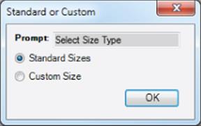
Figure 20.18 The radio buttons allow you to run one rule or the other.
You can test this rule and notice that you can now choose between the two input types, Custom and Standard. If you choose Custom, you can add anything, and you can choose from only the approved standards for the standard inputs.
But what if you enter a value such as 300 for the length? You'll notice that the hole spacing becomes quite large. It would be nice to have a rule to add holes for large custom lengths and widths. In the next exercise, you'll investigate how to do just that.
Use a Message Box to Troubleshoot
Oftentimes, it is helpful to add a message box to return a value to you so you can see what the code is returning. This is particularly helpful when your code is throwing an error. For example, if, when working with a parameter named Shell_OD, you receive an error concerning that parameter, you might temporarily add the following line to visually confirm the value returned for Shell_OD:
MessageBox.Show(Shell_OD, "Test")
Suppressing Features
In this next exercise, two hole features have been added to the part for you. The goal is to create a rule to suppress a hole feature if the spacing is under a specified distance and activate it if the spacing exceeds the specified distance. You'll explore a couple of other tips and tricks along the way. Follow these steps:
1. Click the Open button on the Get Started tab, browse for mi_20a_006.ipt in the Chapter 20 directory of your Mastering Inventor 2015 folder, and open it.
2. From the Manage tab, click the Parameters button.
3. Notice that there are two reference parameters present.
These reference parameters were created in Sketch3, which controls the locations of Hole2 and Hole3. Recall that a reference parameter is created by adding a driven dimension to a sketch. In this case, the distance between the center holes and end holes along the horizontal and vertical edges was dimensioned after the sketch was fully constrained, resulting in the driven dimension/reference parameter. Then, those parameters were renamed.
4. On the Rules tab of the iLogic browser, click and drag the rule named Size Type Input to the top of the list. Since this is the rule that is utilized to choose between the others, it might be best to place it at the top.
5. Add a new rule and call it Suppress Center Holes.
6. From the toolbar along the top of the Rule Authoring pane, select the If…Then…End If button to place the syntax snippet in your rule.
7. Use the drop-down and add Else to the snippet so that you have the following:
8. If My_Expression Then
9. Else
End If
10.Highlight My_Expression in the function code and then look in the Model tab along the top and select Reference Parameters.
11.Select Center_Hole_Space_H from the Parameters subtab on the right and double-click it to replace My_Expression.
12.From the toolbar along the top of the Rule Authoring pane, select the Operators drop-down and notice that it contains a list of all the logic operators. Click >=to include it in your rule after Center_Hole_Space_H and then enter 45 so that the result is as follows:
If Center_Hole_Space_H >=45 Then
On the next line, you will add the function to make the hole feature active.
13.Select Hole2 from the feature tree in the Model tab area and then right-click it and choose Capture Current State.
Capture Current State
You can use the Capture Current State option on any Inventor feature or parameter. You can just delete the unneeded information and keep what is pertinent.
14.Delete all the extra information and keep only the Feature.IsActive line. IsActive can be used to suppress or not suppress any Inventor feature that can be suppressed.
15.Copy that line below the Else and change True to False so the result reads as follows:
16. If Center_Hole_Space_H >=45 Then
17. Feature.IsActive("Hole2") = True
18. Else
19. Feature.IsActive("Hole2") = False
End If
20.Copy your entire block of code and paste it under the original.
21.Change the reference parameter to Center_Hole_Space_V and the hole feature references to Hole3 so your entire rule reads as follows:
22. If Center_Hole_Space_H >=45 Then
23. Feature.IsActive("Hole2") = True
24. Else
25. Feature.IsActive("Hole2") = False
26. End If
27. If Center_Hole_Space_V >=45 Then
28. Feature.IsActive("Hole3") = True
29. Else
30. Feature.IsActive("Hole3") = False
End If
31.Click the OK button to test the rule.
Because the current hole spacing is less than 45 for both of the reference parameters, the hole is suppressed. Next, you'll modify the existing rules to call the Suppress Center Holes rule and format the Custom Size Input rule to include a “soft” warning in the form of a second line in the input boxes.
32.Edit the Standard Size List Input rule and add the following line to the very end (after the UpdateWhenDone function):
iLogicVb.RunRule("Suppress Center Holes")
Of course, you can just type the line in as you are reading it, but for the sake of practice, use the Function Category list to find the RunRule function and double-click it to enter it.
33.Edit the Custom Size Input rule and add the same RunRule line to the end.
34.Change the top two lines of code to read as follows:
35. Length = InputBox("Enter Length" & vbCrLf & _
36. "(max length not to exceed 350)", "Length Input", Length)
37. Width = InputBox("Enter Width" & vbCrLf & _
"(max width not to exceed 300)", "Width Input", Width)
Inserting & vbCrLf & creates a second line in the input line. The underscore preceded by a space provides a carriage return without disrupting the code. This makes it easier to read in the Edit Rule dialog box. When you test the rule, you'll see that that the second line contains a parenthetical statement advising the user of the maximum width. This is a “soft” warning because there is nothing in the rule to prevent the user from inputting values larger than the stated maximums.
Because your rules are changing the size of your part, it would be nice to add a bit of code to adjust the zoom level to match the size of the new part. To do so, you can call an application programming interface (API) object to make this happen with this line:
ThisApplication.ActiveView.Fit
38.Edit the rule named Size Type Input and add the previous line to the end.
39.Add a comment line above it by typing This line Zooms All.
40.To make that line be seen as a comment and not a line of code, simply add an apostrophe to the beginning. The result should be as follows:
41. 'This Line Zooms All
ThisApplication.ActiveView.Fit
Commenting Code
Any text preceded by an apostrophe is read by iLogic as a comment and not interpreted as code. Use this to your advantage by adding notes and documentation to your iLogic code to make editing it in the future easier.
You can also use the Comment and Uncomment buttons found on the toolbar above the top of the Rule Authoring pane to comment out entire blocks of code and then uncomment them later. This is particularly helpful when troubleshooting and working out “what if” strategies while creating rules.
If you anticipate using a particular snippet a lot, you might want to save it to the Custom Snippets tab. To see how this is done, you'll save the Zoom All snippet.
42.Highlight both the comment line and the code line and then right-click and choose Capture Snippet.
43.For the Title, type Zoom All.
44.Click the Use Code As Tooltip button and then click the OK button.
45.Click the Save Custom Snippets button on the toolbar of the Custom Snippets tab and choose a name and location for your custom snippet file.
You're likely beginning to see the power of iLogic and the use of simple rules to create configurations of your model templates. Feel free to experiment with this file to tweak the code as you like, or you can close the file without saving changes and move on to the next section.
Operators
You'll find the use of operators to be a common method of building logic in your iLogic rules. An operator performs a function on one or more objects. Table 20.1 lists some common operators and examples of their uses for quick reference.
Table 20.1 Common function operators
|
Operators |
Description |
Example |
Results |
|
+ |
Adds two values |
12 + 5 |
Returns 17 |
|
– |
Subtracts one value from another value |
12 – 5 |
Returns 7 |
|
* |
Multiplies two values |
12 * 5 |
Returns 60 |
|
/ |
Divides two numbers and returns a floating-point result |
12 / 5 |
Returns 2.4 |
|
\ |
Divides two numbers and returns an integer result |
12 \ 5 |
Returns 2 |
|
^ |
Raises a value to a power |
2 ^ 2 |
Returns 4 |
|
& |
Concatenates two strings |
“Autodesk” & “Inventor” |
Returns “Autodesk Inventor” |
|
> |
Greater than |
12 > 5 |
Returns True |
|
< |
Less than |
12 < 5 |
Returns False |
|
= |
Equal to |
12 = 5 |
Returns False |
|
>= |
Greater than or equal to |
12 >=5 |
Returns True |
|
<= |
Less than or equal to |
12 <= 5 |
Returns False |
|
<> |
Not equal to |
12 <> 5 |
Returns True |
|
Mod |
Divides two numbers and returns only the remainder |
12 Mod 5 |
Returns 2 |
|
And |
Performs a conjunction on two expressions and checks both even if the first is found to be false |
If 12 > 5 And 5 > 7 Then both are True Else at least one is False |
Returns the following: At least one is False |
|
Or |
Performs a disjunction on two expressions |
If 12 > 5 Or 5 > 7 Then at least one is True Else both are False |
Returns the following: At least one is True |
|
AndAlso |
Performs a conjunction on two expressions, but evaluates the second if and only if the first is true |
If 12 = 5 AndAlso 5 < 7 Then both are True Else at least one is False |
Returns At least one is False but doesn't evaluate 5 < 7 |
|
OrElse |
Performs a disjunction on two expressions, but evaluates the second if and only if the first is true |
If 12 = 5 OrElse 5 < 7 Then at least one is True Else at least one is False |
Returns At least one is False but doesn't evaluate 5 < 7 |
Creating iLogic Forms
iLogic forms are used to create a custom user input and control form to work with iLogic rules or to handle parameter and iProperty changes directly. iLogic forms are created with an intuitive drag-and-drop interface that is easy to master.
Working with iProperties and Forms
In this next exercise, you'll explore the use of iProperties in iLogic rules and then create a basic iLogic form to manipulate them. The objective here is to create a rule to do the following:
· Read the available materials from the part file and populate a multi-value parameter list with those values.
· Set the material iProperty using the list box selection.
· Ask the user a question: Is this part to be painted?
· Set the part color iProperty based on the user input.
Follow these steps to explore the use of iProperties and forms:
1. Click the Open button on the Get Started tab, browse for mi_20a_007.ipt in the Chapter 20 directory of your Mastering Inventor 2015 folder, and open it.
2. From the Manage tab, select the Parameters button.
3. Add a new Text user parameter (use the drop-down in the lower-left corner) and call it Materials_List.
4. Right-click the new parameter and choose Make Multi-Value.
5. Add a new value called Generic to the list.
6. Create another new Text user parameter and call it Colors_List.
7. Make it a multi-value parameter also and add the following values (make sure your spelling and capitalization match exactly):
· As Material
· Gunmetal
· Slate
· Tan
· White
8. Close the Parameter dialog and open the iLogic browser. Add a rule named Material and Color Input.
9. Locate and expand the iProperties node in the Function Category list on the left.
10.Find the List Of Materials entry and double-click it to add it to your rule.
11.Clear param from between the parentheses and then select User Parameter from the model tree list at the top.
12.Double-click Materials_List in the Parameters subtab on the right to place it in the quotation marks. Your rule should read as follows so far:
MultiValue.List("Materials_List") = iProperties.Materials
This line retrieves the current list of materials from the part file and uses it to populate the Materials_List parameter you created. Next, you'll add a line to set the material iProperty to be whatever the value of the Materials_List parameter is. And then, you'll do the same for the Colors_List parameter.
13.From the iProperties node in the Function Category list on the left, select Material and double-click it to add it to your rule.
14.Add an equal sign to the end of the line and then ensure that User Parameter is still selected in the model tree list at the top. Double-click Materials_List in the Parameters subtab to add it to the code.
15.Do the same thing for the iProperty function called PartColor and the user parameter called Colors_List so that your final rule code reads as follows:
16. MultiValue.List("Materials_List") = iProperties.Materials
17. iProperties.Material = Materials_List
iProperties.PartColor = Colors_List
18.Click the OK button to exit the Edit Rule dialog box.
Next, you'll build an iLogic form to allow you to easily select a material and a color from a list.
19.In the iLogic browser, switch to the Forms tab and then right-click in the browser space and choose Add Form.
The Form Editor opens and shows the form building tools, as illustrated in Figure 20.19.
Here are the Form Editor tools:
1. Filter Tool (A) Allows you to filter the list on the Parameters, Rules, and iProperties tabs for All, Key, and Renamed
2. Tabs Area (B) Allows you to drag and drop items from the list to the Form Design pane to add controls for your custom interface
3. Form Design Pane (C) Allows you to design a custom interface by doing the following:
§ Dragging and dropping parameters, rules, iProperties, and Toolbox items onto the form
§ Dragging and dropping items on the tree to organize the controls
§ Editing label text
§ Selecting an item to edit its properties in the Properties area
4. Toolbox (D) Allows you to drag and drop controls onto your form
5. Properties Area (E) Allows you to edit the properties for the items selected in the Form Design pane
20.In the Form Design pane (see area C in Figure 20.19), you will see the name of the form listed as Form 1. Change this to read Material and Color Form.
21.Use the Parameters tab in the top-left pane and select the Materials_List parameter. Then, click and drag it up to the top-right pane and drop it under the form name.
22.Notice that an input box is added to the preview form on the right.
23.In the Form Design pane, edit the Materials_List entry to read Select a Material, and then adjust the size of the preview form as needed.
24.Drag the Colors_List parameter to the Form Design pane. Add it above the material control by dragging either item to reorder them.
25.Rename Colors_List to read Select a Color.
26.Click the Colors_List control in the Form Design pane and then locate and expand the Behavior item in the Properties area at the bottom of the dialog box.
27.Set Edit Control Type to Radio Group, as shown in Figure 20.20.
28.Click the OK button to close the Form Editor and then click the Material And Color Form button to bring up the form. Figure 20.21 shows the finished form.
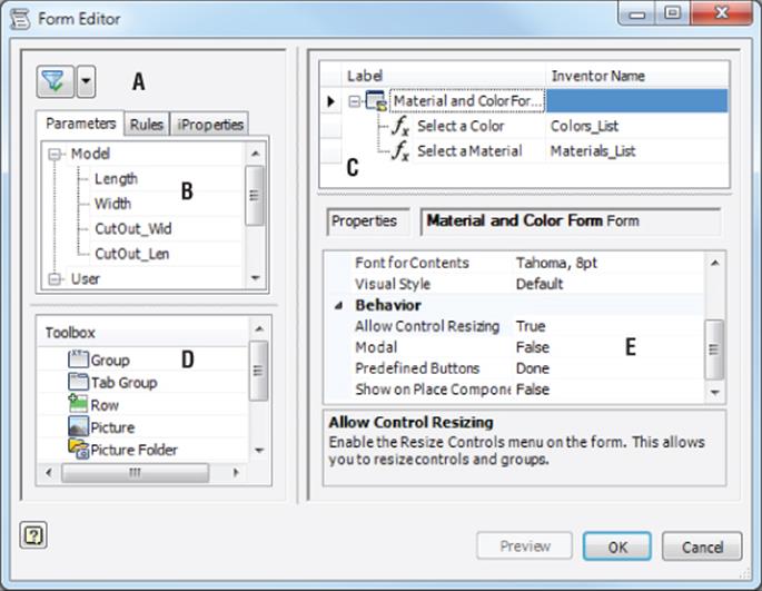
Figure 20.19 The iLogic Form Editor
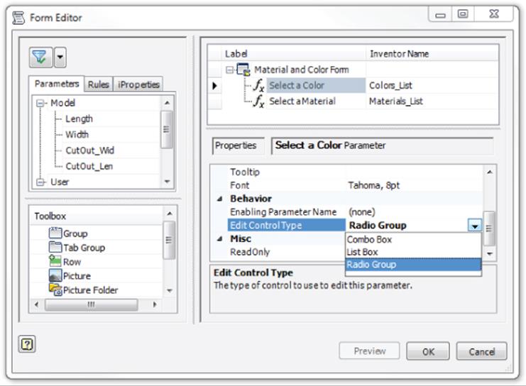
Figure 20.20 Changing the control type
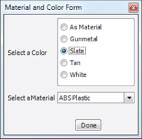
Figure 20.21 The finished Material And Color Form
Play around with the controls, adjusting the material and color to your liking. Recall that setting a color overrides the material color, and therefore, you'll need to set the color to As Material to see the change of material have any effect on-screen. When you've finished, you can close this file without saving changes and continue to the next section.
Form Properties
You can set various options for the form such as the font and color by selecting the node for the form itself in the Form Design pane and then using the Properties area options. The Visual Style property provides a list of color schemes for the form.
By default, the form includes a Done button, but you can select from the Predefined Buttons list. If you're using the OK Cancel or OK Cancel Apply button options, the changes to the model do not take place until a button is clicked. If you're using the default Done button, changes are applied automatically.
Building a Part Configuration Form
In the next exercise, you'll build an iLogic Form for use in configuring a small plate part. This part is a cast part that needs to be machined to include several features. The specifications of those features vary depending on the application, so it would be ideal to set up a template part with an iLogic form to allow quick and consistent configuration of the plate as needed. Follow these steps:
1. Click the Open button on the Get Started tab, browse for mi_20a_008.ipt in the Chapter 20 directory of your Mastering Inventor 2015 folder, and open it.
2. Click the Manage tab and select the iLogic Browser button from the iLogic panel to make sure your iLogic browser is displayed.
On the Rules tab, you'll see three existing rules. Each rule checks a reference parameter found in Sketch6 used to create the sweep feature called Gasket Groove. If a specified reference parameter falls below a set minimum, a warning message is displayed.
3. Set the Forms tab of the iLogic browser active and then right-click the iLogic browser and choose Add Form.
4. Change the Form label from Form 1 to Configure Plate.
5. Locate the Parameters tab on the left and click the plus sign to expand the list of parameters (if it's not already expanded). Notice that the list of parameters includes model, reference, and user parameters.
6. Find the parameter named Mount_Dia and then click and drag it into the Form Design pane on the right. Drop it under the form name in the tree and then change the label to Mount Diameter (A).
7. Add the following parameters to the tree in the same manner and edit their labels to these values (note that Gasket_ID is a user parameter and therefore is found toward the bottom of the Parameters tab):
· Change Hole_Dia to Hole Diameter (B).
· Change Cen_Cen to Center to Center Hole Space (C).
· Change Gasket_ID to Gasket Size (D).
Figure 20.22 shows the results you should have once all four parameters are added and renamed.
8. Select the Group control from the Toolbox and drag it into the tree and then drop it below Gasket Size (D).
9. Change the name of the label from Group 1 to Minimum Dimension Values.
10.Locate the Reference node in the list on the Parameters tab and click and drag the following parameters to the tree. Then edit their labels to these values:
· Change Gasket_Space_Hold to Minimum Space = 2 mm (E).
· Change Gasket_Space_Hold2 to Minimum Space = 2 mm (F).
· Change HoleChecks to Minimum Space = 2.5 mm (G).
Drop the parameters right on the Minimum Dimension Values group so they will land in the group. If you miss, you can just drag and drop them into the group afterward. It's worth mentioning that the values of 2 mm and 2.5 mm come from the existing check rules. The letters listed in parentheses correspond to a legend image to be embedded in the form in the next steps. Figure 20.23 shows the Configure Plate form at this stage.
11.Select the Picture control from the Toolbox and drag to the bottom of the tree.
12.Select the Picture node and then choose the Image property in the Properties pane at the bottom. Select the cell that reads (none) and click the resulting button to browse and select an image to use. Figure 20.24 shows the Image browse button.
13.Click the browse button and locate and select the file mi_20a_008_form_pic.png from the Chapter 20 folder.
The image file will be placed in your form automatically. This image was created by taking a screen capture of an IDW file, detailing the plate, and then using a photo editor such as Microsoft Paint to crop it as needed.
Next, you will change the properties of the Center To Center Hole Space controls to limit the inputs to an approved range. Doing so ensures that the user doesn't specify a value that exceeds the size of the plate or would create a need for custom tooling or a special-order gasket.
14.Select the Center To Center Hole Space (C) control from the tree at the top and then locate Edit Control Type in the Properties pane.
15.Change the control type from Text Box to Slider.
16.Expand the Slider Properties and set them as follows:
· Minimum Value set to 4
· Maximum Value set to 25
· Step Size set to 1
17.Click the OK button to create the form and close the Form Editor.
18.Click the Configure Plate button on the Forms tab of the iLogic browser to bring up the new form. It should look like Figure 20.25.
19.Test the functionality of the form as follows:
a. Set Mount Diameter to 20 mm and notice that a warning message is thrown. Click the OK button in the warning and then set Mount Diameter back to 15 mm.
b. Use the Center To Center Hole Space slider and drag it to the left. You'll notice at 11 mm, the hole becomes a slot. This is because of the Conditional Suppress option on the Slot Cut feature. You can right-click Slot Cut in the browser and choose Properties to see how this is done.
c. Set Mount Diameter back to 20 mm, and click the OK button in the warning box.
d. Use the Gasket Size drop-down to select a smaller size of 100 mm.
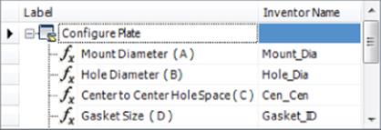
Figure 20.22 Parameters added and renamed
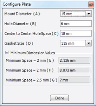
Figure 20.23 The Configure Plate form so far
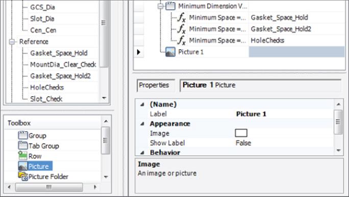
Figure 20.24 Adding an image file
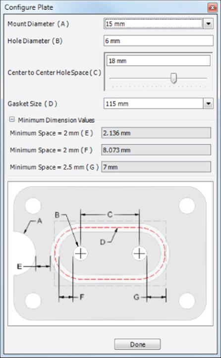
Figure 20.25 The finished plate configuration form
Setting the Form Size
You can set up your forms to maintain a specific size by following these simple steps:
1. Edit the form.
2. In the lower pane of the Form Editor, locate the Behavior section in the Properties list.
3. Set the Allow Control Resizing to True.
4. Click the OK button to exit the Form Editor.
5. Run the form.
6. Right-click and choose Resize Controls; then resize as needed.
7. Then right-click again and choose Exit Resize Mode.
8. Close the form and then edit it again.
9. Now set Allow Control Resizing to False to prevent the form from being accidentally resized in the future.
You can continue adjusting the inputs as you like to test the form. Be aware that if you choose a combination of values resulting in violations of all three minimum space rules, it can be a bit difficult to get the form back to usable values. In the next exercise, you'll add a reset button and more functions to the form to make it a bit more robust.
Using Advanced API Objects
One of the things that makes iLogic so powerful is the ability to use functions from the Inventor API from within an iLogic rule. If you're not familiar with the API, you can find several resources to help you get started by searching the Web for Autodesk Inventor Developer Center.
Adding Rules, Tabs, and Event Triggers
In the next exercise, you'll add a reset button to the form created in the previous exercise. You'll also create a second tab on the form to set standard iProperties. Then, you'll add event triggers to bring the form up automatically when a new part is created from this template and another to prompt for iProperty values when the file is closed. Follow these steps:
1. Click the Open button on the Get Started tab, browse for mi_20a_009.ipt in the Chapter 20 directory of your Mastering Inventor 2015 folder, and open it.
2. Create a new rule named Reset Form and add the following code:
3. 'resets parameters to default values
4. Mount_Dia = 15 mm
5. Hole_Dia = 6 mm
6. Cen_Cen = 18 mm
7. Gasket_ID = 115 mm
iLogicVb.UpdateWhenDone = True
8. To keep this rule from setting those parameter values automatically, you need to click the Options tab and select the Don't Run Automatically check box. Once this is done, you can click the OK button to exit the Edit Rule dialog box.
9. From the Forms tab of the iLogic browser, right-click the Configure Plate button and choose Edit.
10.Set the Rules tab active in the Tabs pane on the left.
11.Click and drag the Reset Form rule into Form Design pane and drop it under the picture at the bottom of the list. This automatically adds a button to run the reset rule, allowing you to quickly reset the form to the original values.
12.Select the Tab Group control from the Toolbox and drag and drop it into the Form Design pane to create a new tab.
13.Rename the tab Size Entry.
14.Drag the tab to the top of the tree and then drag and drop the following items onto Size Entry.
· Mount Diameter (A)
· Hole Diameter (B)
· Center To Center Hole Space (C)
· Gasket Size (D)
15.Drag and drop another Tab Group control into the Form Design pane and rename it Property Entry.
16.Set the iProperties tab on the left active and then drag the following iProperties into the Form Design pane so they reside in the Property Entry tab:
· Part Number
· Description
· Revision Number
Your Form Design pane and the top of your form should look like Figure 20.26.
Next, you'll create a rule to call the Configure Plate form and set it to automatically trigger when the file is initially created (when this part file is used as a template) or opened (when an existing version of this part file is opened for modifications).
17.Create a new rule named Call Form and add the following code:
18. 'displays the specified form
iLogicForm.Show("Configure Plate")
19.Once the rule is created, select the Manage tab and click the Event Triggers button found on the iLogic panel.
20.Select the New Document event in the Rules Triggered By Events dialog box, click the Select Rules button, and then select the Call Form rule. Click the OK button to return to the list of events.
21.Add the Call Form rule to the After Open event using the same steps.
22.Click the Inventor button in the top-left portion of the application screen and then choose Save As and then Save Copy As Template.
23.The template directory opens as specified in the Application Options settings. Save the file as Plate 4792.
24.From the Get Started tab, select New and then make sure you are looking at the main Templates directory folder using the pane on the right. Then select the Plate 4792 template.
25.Once the template is loaded, the Configure Plate form displays, allowing you to configure the plate for the new variation. Use the controls to create a variation and then click Done.
26.Save the file to the Chapter 20 directory of your Mastering Inventor 2015 folder and name it A-4792.ipt.
27.Close the file and reopen it to make sure the Call Form rule is triggered by the After Open event.
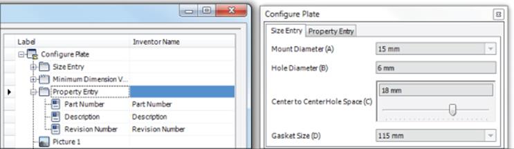
Figure 20.26 The improved form
Working with iLogic forms is quite simple because of the intuitive drag-and-drop interface. You can likely see the power and benefit to using iLogic rules and forms to configure repetitive tasks and to enforce consistency as demonstrated here. Feel free to experiment with this file to add more controls and functionality if you'd like. Or you can close the files used in the previous steps and continue to the next section without saving changes.
Set Global Forms to Read-only
If you create your forms as global forms, they are saved outside of the Inventor file. Once your global forms are created and tested, you might want to prevent them from accidentally being changed by other users (or yourself). To do so, follow these steps:
1. Right-click any empty area of the form panel in the browser.
2. Choose Open Containing Folder.
3. In this folder, locate the XML file with the same name as your form.
4. Right-click and choose Properties.
5. On the General tab, select the Read Only check box.
Working with iLogic Components
Because parts and subassemblies with iLogic rules are often configured to different sizes and with different components, placing them directly into an assembly is generally not the correct method. Changes to the iLogic component will impact every assembly it is placed in. Instead, you will typically use the Place iLogic Component tool to place a copy of an iLogic component into an assembly.
The copy is automatically created in the directory of the assembly you are working in, so it is important to save the assembly before using the Place iLogic Component tool. For example, you have an assembly called 45–1000.iam in a folder named 45–0000. When you attempt to place 45–6799.ipt using the Place iLogic Component tool, it's actually a copy that is placed in the assembly file, and the copy will be named 45–6799–01.ipt. This file will be created in the 45–0000 folder. If you placed another version of 45–6799.ipt into the same assembly using the Place iLogic Component tool, it would be named 45–6799–02.ipt and placed in the 45–0000 folder.
Placing iLogic Subassemblies
When you place an iLogic subassembly, all components in the same directory or subdirectories of that subassembly are copied to the directory of the main assembly and assigned unique names.
Therefore, it's recommended that you organize your iLogic subassembly files with standard models outside of the directory of the subassembly that will be placed as an iLogic component. This can be done by saving them in a Content Center directory or another library directory. When you place the assembly as an iLogic component, these files are not copied to the directory of the main assembly and the iLogic component in the assembly maintains its links to the original files, in their original locations.
You can follow these steps to use the Place iLogic Component tool:
1. From the Component panel of the Assembly tab, click the Place drop-down arrow and select the Place iLogic Component button.
2. Browse for and select the component to be placed. Then click Open.
The component parameters are listed in a small dialog box. If the component contains Key parameters, only those parameters are included in the list; otherwise, all parameters are included. Initially, all parameters are designated as <Free> in the From Assembly column. This indicates that they are not driven by assembly parameters. Changing a free parameter value during placement allows you to configure the component upon placement, and the preview updates to show the changes made.
3. Click the drop-down arrow in the From Assembly column to see the list of assembly parameters available to drive the corresponding parameter. (Driving parameters must exist in the assembly and therefore should be created before placing the iLogic component.)
4. Click the OK button after making your changes.
5. iLogic starts the Place Component tool, allowing you to place a copy of the original iLogic component in the assembly.
iLogic Design Copy
You can use the iLogic Design Copy tool to create copies of assemblies and their documentation. To use the iLogic Design Copy tool, you must first close all of your open Inventor files. Then, in the iLogic panel on the Tools tab, click the iLogic Design Copy button. In the resulting dialog box, you can select the iLogic files to copy. When a file is selected, the referenced files are selected as well. You can also choose to copy unlinked Inventor or non-Inventor files related to the job you are copying.
Once files are selected, you specify the destination folder to which the files will be copied, and you can set file prefixing or suffixing to be appended to the original filenames. Another important option is the ability to maintain or delete the existing rules in the new copy. This allows you to start over with a clean project when needed or use the existing iLogic rules in the new design when that is preferred.
Use iLogic to Fill Out Title Blocks
If you have a Drawn By field and a Date field in your title block, you might find it difficult to remember to edit the iProperties when saving the file or rolling the revision to a new drawing. You can use iLogic to assist with this.
Create an iLogic rule to write the username (pulled from the General tab in the Application Options dialog) and the current date (pulled from your system setting) to the drawing file's iProperties. You can then set your title block fields to read those iProperties. And you can set the rule to be triggered using the Before Save Document event trigger so that the title block is always updated at the time of the file save.
Here is a bit of sample code to do this:
myName= ThisApplication.GeneralOptions.UserName
If iProperties.Value("Summary", "Author") <> myName Then
iProperties.Value("Summary", "Author") = myName
MessageBox.Show("The Title block has been updated", _
"an iLogic message for:" & myName)
End If
iProperties.Value("Project", "Creation Date") = Now
InventorVb.DocumentUpdate()
You can find this and more iLogic samples online at the From the Trenches with Autodesk Inventor blog: http://inventortrenches.blogspot.com.
The Bottom Line
1. Create iLogic rules. Use iLogic rules to document and embed into your models the common design rules that you use every day to determine the decisions required in your design process.
1. Master It How can you add a rule to your part to change the size of it?
2. Edit iLogic rules. A large part of working with iLogic is testing and editing the rules you create. Often, it's best to add a function at a time to the rule and test it along the way.
1. Master It Your rule works, but you have to manually update the model. Do you need to create a new rule to handle the update?
3. Use multi-value list parameters. A common part of any design rule process is selecting from a list of standard entities. You can create multi-value list parameters from Numeric or Text parameters to add lists.
1. Master It How would you create a rule that prompts you to select from a list of approved sizes?
4. Work with multiple rules in the same file. It is often best to create several small rules rather than try to create one large rule that does it all. This helps you maintain and troubleshoot the code later, and it also allows you to use rules in multiple applications without the need to remove or edit existing code. This is particularly true when working with external rules, which might be used in varying applications later.
1. Master It You've created two smaller rules because it makes sense to do so, but when you try to run one, the other is triggered also. Do you need to combine them into one rule?
5. Use conditional statements. Conditional statements are the foundation of any programmed logic. Learning how to use If, Then, and Select Case statements will go a long way in helping you solve logical problems when creating rules.
1. Master It How can you check the value of a parameter or its state with an iLogic rule?
6. Suppress features. Configuring a part file to include and exclude features is often based on engineering decisions you make every day. Setting up your iLogic rules to do this is straightforward, provided the model is well constructed to start with.
1. Master It When you use the Feature.IsActive function on one feature, it causes an error in the part. How can a feature be suppressed without suppressing a dependent feature?
7. Work with iProperties. iProperties are a powerful part of working with Inventor. Being able to retrieve and use metadata helps with all parts of the engineering process. Automating the process of filling out iProperty data with iLogic is a big step forward.
1. Master It Can iLogic be used to update the title block of a drawing?
8. Create iLogic forms. iLogic forms make creating a user interface for your iLogic pursuits quite easy. The drag-and-drop tools provide professional-looking forms with minimal effort.
1. Master It You have existing part files with no iLogic in them, and it would be nice to use the form you created in the most recent design to update those old designs as revisions require it. Can forms be created and shared across part files?
9. Build a part configuration form. Configuring Inventor components saves time, reduces human error, and promotes consistency. Using iLogic forms to configure common designs is a good way to go.
1. Master It Can an iLogic form help with parts that are basically the same but have a lot of variation in the features they include?