Mastering Autodesk Inventor 2015 and Autodesk Inventor LT 2015 (2014)
Chapter 19. Plastics Design Features
When creating thin wall plastic parts, you can choose either of two popular approaches to get started. One approach is to start with a solid and shell it out; the other is to start with a surface and thicken it. Although these methods approach thin wall features from different starting points, the end result can be the same. You can also mix and match the two methods as required to achieve your design.
Typically, once you've established the base feature, you will add other plastic part features. The Autodesk® Inventor® software has several specialized tools for creating plastic part features when you are working in the parts modeling environment. You'll find these tools on the Plastic Part panel of the 3D Model tab. Although many of the other tools covered in this chapter, such as Shell and Thicken/Offset, are used to design all types of parts, they are commonly used along with the plastic-specific tools and, therefore, are covered in this chapter as well.
In this chapter, you'll learn to
· Create thicken/offset features
· Create shell features
· Create split features
· Create grill features
· Create rule fillet features
· Create rest features
· Create boss features
· Create lip and groove features
· Create snap fit features
· Create rib and web features
· Create draft features
· Create an injection mold
Creating Thicken/Offset Features
You can use the Thicken/Offset Feature to add thickness to a surface feature to create a thin wall solid. Although you can use this tool to create surfaces and remove solid material, typically when using Thicken/Offset to create plastic thin wall features, you'll select an existing surface feature to thicken and then set the output type to produce a solid.
To create a thin wall part using the thicken method, follow these steps:
1. Click Open on the Get Started tab, browse for mi_19a_022.ipt in the Chapter 19 directory of your Mastering Inventor 2015 folder, and open it.
If you have not already downloaded the Chapter 19 files from www.sybex.com/go/|masteringinventor2015, please refer to the “What You Will Need” section of the introduction for the download and setup instructions.
2. On the 3D Model tab, select the Revolve tool, and notice that Output defaults to Surface because the sketch is an open profile.
3. For the profile selection, click any solid line in the sketch.
4. For the axis, select the dashed centerline.
5. Leave the extents solution set to Full and click the OK button.
6. On the 3D Model tab, click the Combine tool flyout menu to expose the Thicken/Offset tool.
7. Switch the select mode from Face to Quilt and then select any face on the revolved surface.
8. Set Distance to 2 mm, and change the direction arrow so that the thickened material is placed to the inside of the part.
9. Ensure that the output is set to Solid and then click the OK button.
Notice the sharp edges. Although you could use the Fillet tool to select all the outside edges of the solid and then attempt to set fillets to all the inside edges of the solid, there is an easier way. If you place the fillets on the surface, the thickened solid feature will follow the shape and include the fillets. To do this, continue with these steps.
10.From the browser, select the end-of-part (EOP) marker and drag it above the thicken feature.
11.Select the Fillet tool on the Modify panel and set the radius to 8 mm.
12.Set Select Mode to Feature and then select the revolved surface.
13.When you see a preview of three fillet edges, click the OK button.
14.Drag the EOP marker down below the thicken feature in the browser, and you'll note that the thickened solid now includes the filleted edges.
15.Right-click the revolution feature in the browser and toggle the visibility off.
Figure 19.1 shows the revolved and thickened part. You can close this file without saving the changes and continue to the next section, where you'll create the same basic part but using a different method.
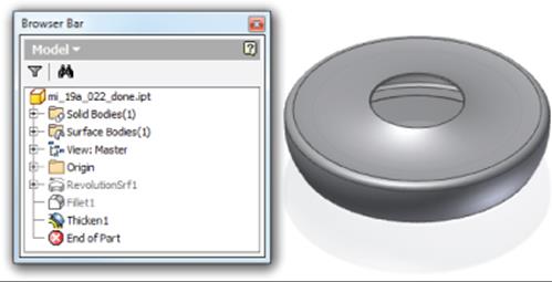
Figure 19.1 A revolved and thickened part
Using Plastic Part Templates
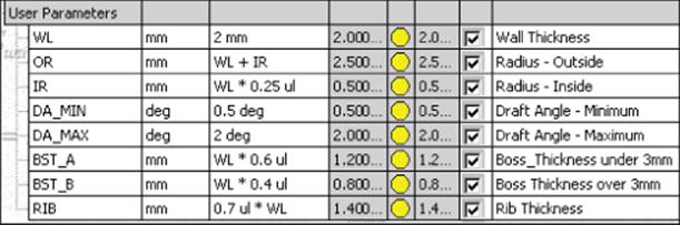
When working with plastic thin wall parts, it is helpful to follow certain design parameters throughout the features of the part to avoid issues with shrinkage and voids caused by uneven cooling once the part comes out of the mold. To help with this, you may want to create a plastic part template with your design parameters already set up. Here is an example of the parameters in such a template with the design rules already set up and ready for use:
Creating Shell Features
Another approach to creating thin wall features and parts is to create a solid and then use the Shell tool to hollow it out. When creating a shell feature, you set the wall thickness and select the faces you want to remove. Material from the interior of the part is removed, resulting in a cavity. To create a thin wall part using the shell method, open mi_19a_024.ipt in the Chapter 19 directory of your Mastering Inventor 2015 folder and then follow these steps:
1. On the 3D Model tab, select the Revolve tool, and notice that Output defaults to Solid because the sketch is closed. The profile and axis selections will automatically select because there is only one possible solution for each.
2. Leave the extents solution set to Full and click the OK button.
3. Click the Shell button on the Modify panel of the 3D Model tab.
4. Select the circular face on the top of the revolution feature as the Remove Faces selection.
5. Ensure that the direction is set to Inside, set the thickness to 2 mm, and then click the OK button.
Notice the odd result at the opening of the part. You will fix this by creating a boundary patch surface and then using the Thicken/Offset tool to recut the hole. You'll also place some fillets on the sharp outside edges.
6. Select the Boundary Patch tool on the Surface panel.
7. Click the larger-diameter edge of the center hole for the BoundaryLoop selection and click the OK button. This creates a surface feature you'll use to recut the hole.
8. On the 3D Model tab locate the Modify panel and look for the Thicken/Offset tool (note you might need to look in the flyout menu). Select the Thicken/Offset tool and click the boundary patch's surface.
9. Set Solution to Cut, set Distance to 2 mm, and set the direction to go down into the part.
10.Make sure the output is set to Solid and then click the OK button.
11.Select the Fillet tool on the Modify panel and set the radius to 8 mm.
12.Select the three outside edges—two along the bottom and one along the top. Be certain these are the outside edges and not the inside edges; then click the OK button.
13.Drag the fillet feature above the shell feature in the browser. This will allow the shell to follow the outside fillets and translate them to the inside edges. If you cannot drag the fillet above the shell feature, mostly likely you have inadvertently selected an inside edge. If so, the fillet cannot exist before the shell because it is dependent on the edge created by the shell.
14.Right-click the boundary patch feature in the browser and toggle the visibility off. Figure 19.2 shows the revolved and shelled part.
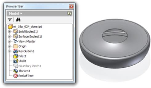
Figure 19.2 A revolved and shelled part
If you were to compare the parts created by the Thicken/Offset method and the Shell method, you would find that the two are not quite identical. The difference is in the opening cutout. In the shelled version, a boundary patch was used to recut the opening down into the part (along the y-axis). In the thickened version, the opening was left in its natural condition. You could use the Boundary Patch tool to clean up the opening in that case as well.
Using either method, it is also important to consider a draft angle for the walls that are in the direction in which a mold would be separated. Not including drafts early on can lead to a lot of difficult cleanup work in the long run, before a mold can be created. You can close this file without saving the changes and continue to the next section, where you'll explore the Split tool.
Reordering Shell Features
You may find that you've added a previous feature that gives an incorrect result when creating shell features later in the design. Often, you can just click the shell feature and drag it above the other features to let it rebuild. To explore this, you can open the file mi_19a_064.ipt in the Chapter 19 folder, click Shell1 in the browser, and drag it above Extrusion2. When you do so, you'll see that the resulting part is quite different from when the shell was created after the extrusion and fillet features.
Creating Split Features
Often when designing plastic parts, it is useful to create mating parts within the same file. To do this, you can use the Split tool to divide a single body into two mating bodies. You can also use the Split tool to split the surfaces on a solid so that they can be manipulated individually. To see how the Split tool is used, open the file mi_19a_026.ipt in the Chapter 19 directory of your Mastering Inventor 2015 folder and then follow these steps:
1. Expand the Solid Bodies folder in the browser, and notice that there is currently only a single solid listed in the folder. You will use the Split tool to divide this into two separate solids.
2. On the 3D Model tab's Modify panel, select the Split tool (look in the flyout menu under the Thicken/Offset or Combine tool).
3. For the Split tool selection, click the sketch profile running through the part.
4. For the method, click the Split Solid button (third from the top), which will split the existing part into two separate solids.
5. Click the OK button and notice that Solid1 has been replaced with two new solids in the Solid Bodies folder.
6. To work with just the top solid, select it in the Solid Bodies folder of the browser, right-click, and choose Hide Others.
7. Next, you'll create a 3D sketch to split the surface of the solid. Use the Sketch drop-down on the 3D Model tab and select Start 3D Sketch.
8. On the 3D Sketch tab, select the Silhouette Curve tool, choose the solid as the Body selection and the visible y-axis as the Direction selection, and then click the OK button.
9. This creates a sketch curve along the face where a beam of light shining down from above would create a shadow. Click Finish Sketch to exit the 3D sketch.
10.Select the Split tool again and choose the 3D Sketch curve for the Split tool selection.
11.For the Face selection, choose the face that the 3D Sketch curve is encircling. Ensure that the Faces option is set to Select and not All. This will split just the outside face of the part, whereas All would split both the outside and inside faces. Click the OK button.
12.Now select the Thicken/Offset tool, choose the bottom half of the face you just split, and set Distance to 1 mm.
13.Ensure that Output is set to Solid, Solution is set to Join, and Direction is thickening out from the part; then click the OK button.
14.Right-click the thickened part you just created in the browser and choose Properties.
15.Set Feature Appearance to Blue – Glazing or something similar and click the OK button.
16.Right-click the solid in the Solid Bodies folder and choose Properties. Enter Cover for the name. Click the Update button to set the general properties of this solid. You'll notice also that you can set the color for the entire solid body here. Selecting the Clear All Overrides check box would reset the blue thicken feature to abide by the color of the entire solid. Feel free to choose a color of your liking and then click the OK button.
17.Right-click the solid in the Solid Bodies folder and choose Show All to turn the visibility of the other solid back on.
There are a number of uses for a multi-body part, but for this type of product they are invaluable. You can close this file without saving the changes and continue to the next section, where you'll learn to create grill features.
Turn on the Plastic Parts Tool Panel
If you do not see the Plastic Part tool panel on your 3D Model tab, you might need to enable it by right-clicking anywhere on the tab and then choosing Show Panels and then Plastic Part. Once this is done, you will see the Plastic Part panel on the 3D Model tab.
Creating Grill Features

You can use the Grill tool to create vents and openings on thin wall parts to provide access and airflow to parts housed within an exterior part. To create grill features, use the Grill tool to project 2D sketches onto the surface of the part to create various raised or recessed features. Although the boundary sketch is the only required grill element, you can create islands, ribs, and spars, and then give them all a draft angle. You can also check the flow area of the opening to ensure that it meets the required area. Open the filemi_19a_028.ipt in the Chapter 19 directory of your Mastering Inventor 2015 folder and then follow these steps to create a grill feature:
1. Select the Grill tool from the Plastic Part panel of the 3D Model tab. You'll see a sketch with all the various elements of what will become the grill within it. Figure 19.3 shows the sketch elements separated out into the grill elements.
2. For the Boundary profile, select the outer profile of the sketch, as identified in Figure 19.3. Set Thickness to 2 mm, Height to 6 mm, and Outside Height to 2 mm, as shown in Figure 19.4.
3. Click the Island tab and select the elliptical profile of the sketch, as identified in Figure 19.3. Leave Thickness set to 0 mm so that the island is a solid fill.
4. Click the Rib tab and select the four arcs identified as the ribs in Figure 19.3. Set Thickness to 2 mm, Height to 4 mm, and Top Offset to 2 mm, as shown in Figure 19.5.
5. Click the Spar tab, and select the two lines identified as the spars in Figure 19.3. Set Top Offset to 2 mm, Thickness to 6 mm, and Bottom Offset to 0 mm, as shown in Figure 19.6.
6. Click the ![]() button at the bottom of the dialog box and note the Flow Area setting; then click the OK button to create the grill feature.
button at the bottom of the dialog box and note the Flow Area setting; then click the OK button to create the grill feature.
7. Next, you'll pattern the grill feature around the parts. Click the Circular Pattern tool (located next to the Work Features tools).
8. Select the grill feature for the Features selection and then click the visible y-axis for the Rotation Axis selection.
9. Enter 3 for Occurrence Count and 90 deg for Occurrence Angle.
10.Click the Midplane button to set an occurrence on each side of the original grill feature and then click the ![]() button.
button.
11.In the Positioning Method area, select Incremental to set the spacing of the grills at 90 degrees each and then click the OK button. Figure 19.7 shows the patterned grill features.
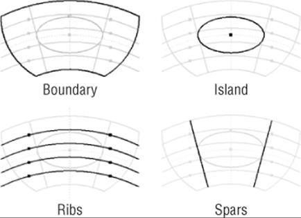
Figure 19.3 Grill elements
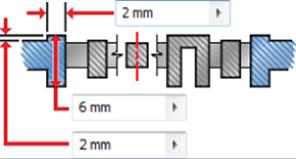
Figure 19.4 Grill boundary settings
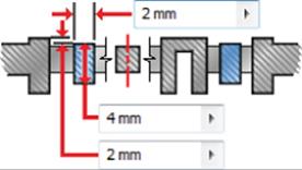
Figure 19.5 Grill rib settings
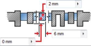
Figure 19.6 Spar rib settings
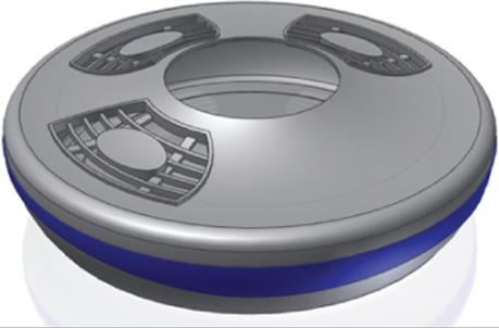
Figure 19.7 Grill features patterned
Feel free to edit the grill feature and experiment with the options, adding a draft angle and so on. You might want to drag the EOP marker above the pattern feature before doing so to allow the edits to take place more quickly. Then just drag it back down once the edits are complete. When you've finished, you can close this file without saving the changes and move on to the next section, where you'll learn about rule fillet features.
Creating Rule Fillet Features
With rule fillets, you can create fillets based on a list of rules you've set up to determine which edges to fillet. This approach can be a powerful time-saver when you're working with plastic parts because it allows you to create many fillets all at once without having to select each and every edge. When a part feature is changed with significance to the rule-based fillets, the rule is evaluated to determine whether it still applies. If so, the fillets are regenerated for new edges that fit the rule and discarded for edges that do not. Although the Rule Fillet tool is categorized as a plastic feature tool, you can use rule-based fillets for any part you design.
Open the file mi_19a_030.ipt in the Chapter 19 directory of your Mastering Inventor 2015 folder and then follow these steps to create a rule fillet feature:
1. Expand the Solid Bodies folder in the browser, right-click the solid named Cover, and choose Hide Others.
2. Select the Rule Fillet tool on the Plastic Part panel.
3. Click the drop-down under the Source column and select Face.
4. Rotate the part around and select the underside face of the grill features (they've each been colored yellow for easy identification).
5. Set the Radius to 2 mm and then set the drop-down in the Rule column to Incident Edges.
6. In the Options area, deselect the All Rounds check box, leaving All Fillets selected.
7. In the Incident Edges area, select the visible y-axis as the Direction selection and then click the OK button to create all the previewed fillets. Figure 19.8 shows the results of the rule fillet on one of the grill faces.
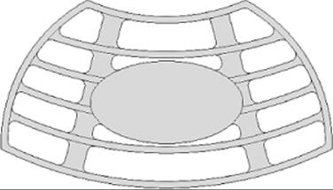
Figure 19.8 An example of rule fillets
You'll notice that the edges, where one of the spars meets the grill boundary along the top, did not receive fillets. This is because those edges do not qualify according to the rule of incident edges. Although it might seem as if the rule fillet has malfunctioned, close inspection of the grill feature will show there is a small gap between the spar and the boundary face. To resolve this, the lines in the grill sketch used for the spars would need to be extended past the boundary edge. If you edit Sketch3, you can see where the issue is.
Here are brief descriptions of the results of the Rule Fillet tool when Faces is selected:
1. Incident Edges Only edges contacting the source faces that are parallel to a selected axis (within a specified tolerance) are filleted.
2. All Edges Edges generated by the selected faces and other faces of the part body are filleted.
3. Against Features Two selection sets are created: a “source” selection and a “scope” selection. Only edges formed by the intersection of the faces in the source with features in the scope selections are filleted.
Here are brief descriptions of the results of the Rule Fillet tool when Features is selected:
1. All Edges Edges generated by the selected features and the part body are filleted.
2. Against Part Only edges formed by the intersection of the faces of the feature(s) and the faces of the part body are filleted.
3. Against Features Two selection sets are created: a “source” selection and a “scope” selection. Only edges formed by the intersection of the features in the source with features in the scope selections are filleted.
4. Free Edges Only edges formed by faces of the selected feature are filleted.
When you have finished with this part, you can close the file without saving changes and move on to the next topic: rest features.
Creating Rest Features
A rest feature is a shelf or landing area applied to a curved or slanted face of a plastic part, often used as a surface on which to mount other components. The results of the rest feature are largely dependent on the orientation of the rest sketch in relation to the target body and the combination of settings and selections you choose. The Through All option will extend the rest profile through the extents of the target body, and the direction arrow will change the results, as you can see by comparing Figure 19.9 and Figure 19.10.
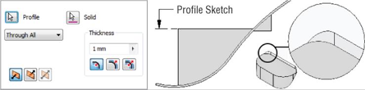
Figure 19.9 Through All termination with the direction set downward
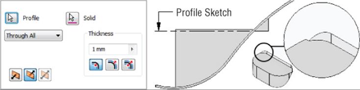
Figure 19.10 Through All termination with the direction set upward
Additionally, you can set a Distance extent. Figure 19.11 shows a rest created 25 mm off the profile sketch in both directions.
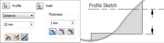
Figure 19.11 Using Distance extents for a rest
You can also set the rest to terminate using a selected surface. Figure 19.12 shows a rest set to use the target body surface as a termination, with the direction set to go up from the sketch. The result adds material but does not create a pocket.
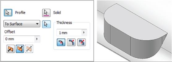
Figure 19.12 A rest using a surface termination
You can use the More tab in the Rest dialog box to set Landing options such as taper angles and termination settings. Open the file mi_19a_032.ipt in the Chapter 19 directory of your Mastering Inventor 2015 folder and then follow these steps to create a rest feature:
1. Expand the Solid Bodies folder in the browser, right-click the solid named Cover, and choose Hide Others.
2. On the Plastic Part panel, select the Rest tool. Because only one profile is available in the visible sketch, it is selected automatically.
3. Set the direction arrow to point up (use the flip arrow on the left).
4. Set the thickness to 2 mm and set the thickness direction to Outside.
5. Click the More tab, set the Landing Options drop-down to To Surface, and then select the visible surface. Set the landing taper to 12 deg and then click the OK button.
6. Turn off the visibility of the landing surface and inspect the results. You'll notice that the surface contours are translated to the tapered faces. If this is not the result you want, you can use the Delete Face option to clean up the contours.
7. On the Modify panel, click the small black arrow to expose the flyout menu and then select the Delete Face tool.
8. Select the Heal check box. Then select the four contoured faces, as shown in Figure 19.13, and click the OK button.
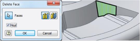
Figure 19.13 Deleting and healing faces
The Delete Face tool is a good way to clean up geometry when needed, but it should not be used indiscriminately, because it may create unpredictable results during feature edits. If you have the option to edit an existing sketch or feature to get the same result as using the Delete Face tool, then that is typically the best option.
There are also times when cleaning up geometry can be bypassed by using a different technique. Rather than cleaning up an interior corner to apply an edge fillet, you may be able to apply a two-face fillet and have the fillet feature “absorb” the inconsistent faces that would be patched over. Also, it is a good idea to create small selection sets to delete multiple faces rather than trying to delete them all at once. For example, in this design you would need to delete the contours on the sides of the rest feature on all the inside and outside faces to remove the contours completely. This would be best to do as several different features, each created with the Delete Face tool. Once you've experimented with the Delete Face tool, you can close this file without saving changes and continue to the next section, where you'll learn about boss features.
Creating Boss Features
To hold plastic parts together without risking damage to the thin wall features, boss features are often used to provide a more rigid connection point than just a simple hole. You can use the Boss tool in Inventor to create matched pairs of bosses on mating parts. The half accepting the fastener is the head, and the other half is the thread. You can create both types of bosses using the Boss tool. When required, you can add strength ribs so that the boss features will not be snapped off under load. As a rule, you should consider adding ribs when the length of the boss exceeds the diameter by more than three times.
Open the file mi_19a_034.ipt in the Chapter 19 directory of your Mastering Inventor 2015 folder and then follow these steps to create boss features:
1. Expand the Solid Bodies folder in the browser, right-click the solid named Base, and choose Hide Others.
2. Because the Base part has an uneven edge, the boss features to be created will be different heights. To locate the bosses, you will first create work points. Select the Point tool on the Work Features panel.
3. To create a work point, select the edge of Work Plane4 and then select the inside edge of the base near the intersection of the work plane and the edge.
Repeat Command for Work Features
When you start any of the work feature tools (Work Planes, Work Axis, and Work Point), you can right-click and choose Repeat Command to set the work feature tools to stay on until you right-click and choose Done. This helps when you are creating a lot of work features because you do not have to click the button each time.
4. Repeat this for Work Plane5 and the inside edge of the part. You'll note that the work points are placed at different heights from the bottom of the base part. Figure 19.14 shows the resulting work points.
5. Next, you will create grounded work points to establish the inset location for the boss features. Use the drop-down on the Work Features panel to select the Grounded Point tool.
6. Select the first work point you created at the intersection of the part edge and Work Plane4. You will see the 3D Move/Rotate dialog box, and the triad will appear at the work point location.
7. Click the Redefine Alignment Or Position button in the dialog box.
8. Next, select the small plane on the triad running between the green y-axis and the red x-axis (you might need to rotate your view). Then select the edge of Work Plane4. The triad will realign to the work plane.
9. Now you are ready to place the grounded work point. To do so, first click the red cone shape (arrowhead) of the triad for the x-axis. This will isolate x-axis input in the dialog box. Enter 15 mm and click Apply. This will create a grounded work point.
10.Next, click the Redefine Alignment or Position button to redefine the triad location. Click the black/purple ball at the center of the triad first, and then select the work point at the intersection of the Work Plane5 and the inside edge of the part.
11.Click the blue cone shape (arrowhead) of the triad for the z-axis. This will isolate the z-axis input in the dialog box. Enter −15 mm (or just click and drag the blue arrowhead into position). Then click the OK button. This will create a second grounded work point and exit the Grounded WorkPoint tool.
12.Now you are ready to create the boss features. Select the Boss tool on the Plastic Part panel.
13.Make sure the Placement drop-down is set to On Point and then select the two grounded work points for the Centers selection. Click the visible y-axis for the Direction selection, and ensure that the preview shows the bosses extending down toward the part base. If they do not, use the Flip arrow to change the direction.
14.Click the Head tab. Note the buttons on the left of the dialog box. If you click the lower one, the Head tab becomes the Thread tab, allowing you to place a different boss type. In the Head tab, click the (+) plus button next to the Draft Options area to view the draft inputs available. You can leave the inputs at the defaults.
15.Click the Ribs tab and select the Stiffening Ribs check box to set these options active. Enter 4 in the Number Of Stiffening Ribs input box.
16.Enter 6 mm for the Shoulder Radius input and then click the (+) plus button next to the Fillet Options area to view the fillet inputs available. Leave the inputs at the defaults.
17.Click the Start Direction button at the bottom of the dialog box and then select either Work Plane4 or Work Plane5 to establish the direction. (You can also just enter 45 degrees as the angle, in this particular case.)
18.Click the OK button to create the boss features. You'll notice that each is created at a different height.
19.Use the Mirror tool to mirror the boss feature, using the YZ origin plane as the mirror plane. Figure 19.15 shows the completed bosses.
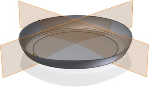
Figure 19.14 Work point locations
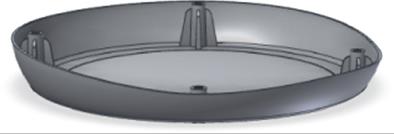
Figure 19.15 Plastic boss features
Now that the Base half of this design has the head-boss features completed, you can create the sketch or work points at the centers of each boss, toggle the visibility of the cover and base so that the cover is visible, and then use those points to create the thread bosses in the cover in the same manner you just created the head bosses in the base. To explore the placement of boss features using a sketch, you can open the file mi_19a_035.ipt from the Chapter 19 directory of your Mastering Inventor 2015 folder. Once you've finished exploring the Boss tool, you can close the file without saving changes and continue to the next section.
Turning Off Work Feature Visibility
Recall that it is a best practice to right-click and toggle off the visibility of each work feature you create once you have finished using it. Leaving the visibility on or using the Object Visibility display override at the part level can make managing work features difficult at the assembly level.
Creating Lip and Groove Features
Lip and groove features are used to mate two parts together so that they fit together precisely. You can use the Lip tool in Inventor to create either the lip or the groove of the part by specifying a path consisting of a set of tangent, continuous boundary edges. You can also use work planes to establish path extents where a lip is not needed around an entire edge. Open the file mi_19a_036.ipt from the Chapter 19 directory of your Mastering Inventor 2015 folder and then follow these steps to create lip features:
1. Expand the Solid Bodies folder in the browser, right-click the solid named Base, and choose Hide Others.
2. Select the Lip tool on the Plastic Part panel and set the type to Lip by clicking the Lip button on the left side of the dialog box.
3. Select the inside edge along the top of the part for the Path Edges selection and then select the top face for the Guide Face setting.
4. Next click the Lip tab, set the outside angle to 10 degrees and the clearance to 0.5 mm, and then click the OK button. Figure 19.16 shows the Lip selections.
5. Next, you'll create the groove on the Cover solid. Expand the Solid Bodies folder in the browser, right-click the solid named Cover, and choose Hide Others.
6. Select the Lip tool and set the type to Groove by clicking the Groove button on the left side of the dialog box.
7. Select the inside edge of the part for the Path Edges selection and then select the Pull Direction check box in the dialog box. Next, select the top face of one of the bosses to establish a pull direction.
8. Next click the Groove tab, set the outside angle to 10 degrees and the clearance to 0.5 mm and then click the OK button.
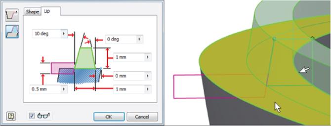
Figure 19.16 Creating a lip feature
Note that if you did not set a clearance value, you would likely get an error. The clearance value is useful for creating a planar surface along the path where needed. You can experiment with different settings and values by editing the lip features if you would like, and then you can close the file without saving changes.
Creating Snap Fit Features
Snap-fit features are used to secure a plastic part to another part. Although you can model any number of snap-fit connections using the standard modeling tools, Inventor includes a tool to create the common hook-and-loop cantilever snap fit. Figure 19.17 shows a few common snap fits you might create with the Snap Fit tool and standard modeling tools.
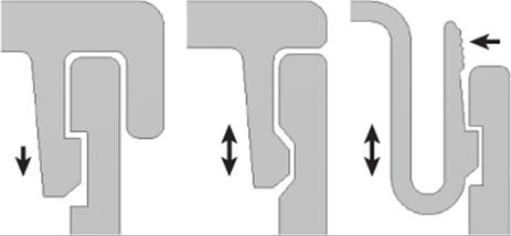
Figure 19.17 From left to right: a permanent locking snap, nonlocking snap, and U-shaped removable locking snap
To insert a snap fit, select an insert point made of either a sketch point or a work point. Open the file mi_19a_038.ipt in the Chapter 19 directory of your Mastering Inventor 2015 folder and then follow these steps to create snap fit features:
1. Bring an existing part into the design using the Derive tool. On the Manage tab, click the Derive button.
2. Locate and select the file mi_19a_099.ipt in the Chapter 19 folder and then click Open.
3. In the Derived Part dialog box, select the first button for the Derive Style to create a single solid-body part with merged seams between planar faces.
4. Next expand the Solid Bodies folder and make sure Solid1 is colored yellow, denoting that it is set to be derived into your current design. Expand the Work Geometry folder, set Work Axis1 to be derived as well, and then click the OK button. You can use the ViewCube to return to the home view.
5. You'll now use the derived part to subtract material from the Cover part so that it will fit into the opening. Click the 3D Model tab and then select the Combine tool on the Modify panel.
6. For the Base selection, select Cover. For tool body, select the derived part. Set the solution to Cut, click the Keep Toolbody check box, and click the OK button.
7. When the tool body component (in this case the derived part) is combined with the base part, its visibility is automatically toggled off. Expand the Solid Bodies folder, and you'll see the derived part listed as a solid with its visibility turned off.
8. Next, you'll create a work point to set the location of the snap fit feature. Select the Point tool on the Work Features panel and zoom into the yellow face located on the cutout of the cover. Select the midpoint along the top edge of the yellow face to set the work point.
9. Now you're ready to create the snap fit. Select the Snap Fit tool on the Plastic Part panel.
10.Ensure that the Placement drop-down is set to On Point and the Cantilever Snap Fit Hook button is selected (on the left of the dialog box).
11.For the Centers selection, click the work point you created.
12.For the Direction selection, click the visible y-axis.
13.For the Hook Direction selection, click the derived work axis running through the yellow face.
14.Use the Flip button to set the direction correctly if the preview shows it facing down.
15.Ensure that the Extend check box is selected so that the snap will match the contour of the curved face on which it is being created. The Extend check box might make the preview of the snap fit feature look as if the feature is going to build to the wrong side of the yellow face, but it should be correct if you've followed the previous steps.
16.Click the Beam tab, set the Beam Length setting to 7 mm, the Beam Width At Hook setting to 9 mm, and the Beam Width At Wall setting to 10 mm.
17.Click the Hook tab, and take a look at the settings; leave these settings at the defaults, and then click the OK button.
18.Use the Circular Pattern tool to pattern the hook around the opening for a total of three.
19.On the Solid bodies tab, right-click all of the solids, and choose Show All. Investigate the snap fit, and note that the derived part has the mating half of the hook built in. Figure 19.18 shows the completed snap fit feature.
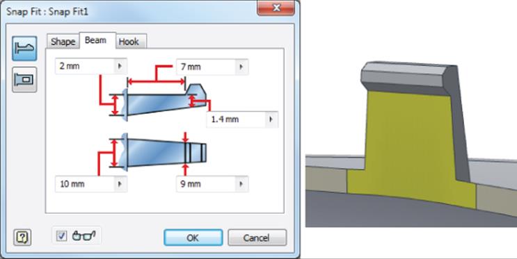
Figure 19.18 A snap fit feature
You can turn on the derived solid from the Solid Bodies folder to check to see how the snap feature fits with the derived part. Once you're done, you can close the file without saving changes.
For more on snap fit features, you can open the file named mi_19a_040.ipt in the Chapter 19 folder to experiment with the various snap fit settings. Use the work points to place hook and loop features to your liking. You can also open mi_19a_042.ipt for comparison. This file contains two halves of a simple plastic box. Examine the model features to see how the hook and loops were created in combination with extrude features to get a precise placement.
Working with Multi-bodies
At any point during your design, you can save the solids within a multi-body part as individual parts and even have them automatically placed into an assembly by using the Make Components tool. Creating multiple solid bodies in a single-part file offers some unique advantages compared to the traditional methods of creating parts in the context of an assembly file. You explored the steps for doing this in Chapter 5, “Advanced Modeling Techniques.”
Creating Rib and Web Features
Ribs and webs are often used in plastic parts to prevent warping and to add stiffness to thin wall parts. To create a rib feature, first create an open profile sketch to define the cross section. Then define the direction and thickness. If the rib feature runs perpendicular to the sketch plane, you can add a draft taper. By default, the profile extends to intersect the next face. To create a rib network, you can select multiple sketch profiles at once. Alternatively, you can create a single rib feature and then pattern and/or mirror it.
Open the file mi_19a_044.ipt in the Chapter 19 directory of your Mastering Inventor 2015 folder and then follow these steps to create rib features:
1. You'll notice there is a small diagonal line sketched in the corner of the part. This will be the sketch profile of the first rib feature. Select the Rib tool on the Create panel (located in the flyout menu under the Sweep tool), and the sketch profile will be selected automatically.
2. Select Rib Type from the two buttons on the left side of the dialog box to switch the type of rib being created.
Normal To Sketch Plane Extrudes geometry normal to the sketch plane. The thickness is parallel to the sketch plane.
Parallel To Sketch Plane Extrudes geometry parallel to the sketch plane. The thickness is normal to the sketch plane.
3. Use the direction buttons if needed to ensure that the rib is going from the sketch toward the bottom corner of the part.
4. Set the thickness to 1 mm and use the arrows to adjust the direction in which the thickness is applied. In this case, you want to use the Midplane option.
5. Click the OK button, and notice how the rib extends to the profile.
6. Next, right-click Sketch3 in the browser and choose Visibility to make it available for use.
7. Select the Rib tool again, make sure the Normal To Sketch Plane option button on the left of the dialog box is selected, and select the four lines and the ellipse as profiles.
8. Toggle the Extend Profile check box off and on to notice the difference in the preview. Ensure that this check box is selected so that the profiles do extend.
9. Set the thickness to 1 mm and use the arrows to adjust the direction in which the thickness is applied. In this case, you want to use the Midplane option.
10.To explore the Finite option, click the Finite button and type 3 mm. This holds the depth of the ribs to 3 mm rather than allowing them to automatically terminate at the base. Set this option back to use the To Next option.
11.Click the Draft tab and enter 5 deg in the Taper input. Ensure that the Hold Thickness option is set to At Root.
At Top Holds the specified thickness at the sketch plane.
At Root Holds the specified thickness at the intersection of the rib feature and the terminating face.
12.Click the Boss tab and make sure the Select All check box is selected. You will see bosses added at the locations of the four center points found in the sketch. You can use the Centers button to add or remove bosses as needed.
13.Set Diameter to 4.
14.Set Offset to 3.
15.Enter 12 for Draft Angle and then click the OK button to create the webbed rib and bosses feature.
To complete the part, you can use the Mirror tool and the XZ origin plane to copy the first rib to the opposite side of the part. Once it's mirrored, you can use the Rectangular Pattern tool to pattern the mirror feature 10 mm toward the end of the part. Finally, use the Mirror tool and the YZ origin plane to add four identical ribs to the opposite end of the part. Now if you make a change to the original rib feature, the copies will update as well. Figure 19.19 shows the finished example.
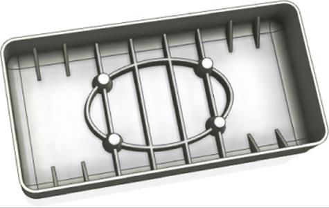
Figure 19.19 Complete rib features
Creating Draft Features
Taper or draft often needs to be applied to part faces so the part can be extracted from the mold in which it is manufactured. You can create draft features in three ways:
1. Fixed Edge This method works by selecting a pull direction and then selecting the faces/edges on which to apply the draft.
2. Fixed Plane This method works by selecting a fixed face and applying drafts to the faces intersecting it.
3. Parting Line This method works by selecting a sketch to define the parting line where the top and bottom halves of a mold form would meet.
To explore the Fixed Edge and Fixed Plane methods, open the file mi_19a_046.ipt in the Chapter 19 directory of your Mastering Inventor 2015 folder and then follow these steps to create draft features:
1. Select the Draft tool on the Modify tab (located in the flyout menu under the Shell tool).
2. For the Pull Direction selection, click the yellow base face.
3. To select the faces, you will click the green faces near the edge that contacts the yellow base face. If you move your mouse pointer over the faces before selecting them, you will see that the edge closest to your mouse pointer will be selected. If you accidentally select an extra or errant edge, you can press the Ctrl key and deselect it.
4. Enter 5 deg for the Draft Angle and then click the OK button. You'll notice the top faces of the thin walls have been reduced because of the draft taper. To remedy this, you'll place a draft on the outside faces also.
5. Rotate the part around so you can see the red and blue faces and then click the Draft tool again.
6. This time, click the Fixed Plane button on the left of the dialog box.
7. Select the red face for the Fixed Plane selection and ensure that the arrow is pointing out.
8. Select the blue faces for the Faces selection, enter 5 deg for the Draft Angle, and then click the OK button.
You can close this file without saving changes and then open the file mi_19a_048.ipt in the Chapter 19 folder to compare how creating the same tapers is made easier by the inclusion of the corner fillet.
Draft Analysis
You can analyze your part for proper draft using the Draft Analysis tool found on the Inspect tab. This tool allows you to specify a pull direction and a draft taper to check against. If faces are found to be insufficient, they are shown by color variations correlating to departure from the specified draft. This can be particularly helpful for complex corners and areas of a part where drafted faces are blended together.
Once they are created, draft analyses are saved in the browser in a folder called Analysis. You can create multiple analyses and turn them on by double-clicking them. To turn existing analyses off, simply right-click the Analysis folder and choose Analysis Visibility.
To explore the final method of creating draft features, open the file mi_19a_050.ipt from the Chapter 19 directory of your Mastering Inventor 2015 folder; then follow these steps:
1. Select the Draft tool on the Modify tab.
2. Click the Parting Line button on the left of the dialog box.
3. For the Pull Direction selection, click the yellow face of the part.
4. For the Parting Line selection, click the projected loop that encircles the part.
5. For the Faces selection, choose an outer face of the part.
6. Click the Asymmetric button so that you have two separate draft angle inputs.
7. Enter 3 for the first angle and 6 for the second angle and then click the OK button to create the draft feature.
As you can see, creating a draft using the parting line option is quite simple. Creating the sketch to use as a parting line is generally done by using the Project Cut Edges option when working with a 2D sketch or by using the Include Geometry tool or the Intersection Curve tool when working with a 3D sketch. You can open the file mi_19a_052.ipt from the Chapter 19 folder to explore an example of the parting line created from an extruded surface and a 3D intersection curve created in a 3D sketch. Figure 19.20 shows a parting line used to create a draft feature.
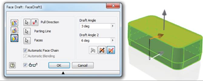
Figure 19.20 Draft using a parting line

Plastic Parts and Cooling Shrinkage
Designing plastic parts of uniform wall thickness is typically a fairly easy task when the part consists of a simple shell. However, when bosses and ribs are introduced, the resulting tees and feature intersections can create cross-section thicknesses that are significantly thicker than the wall thickness average. As is often the case when modeling 3D parts, there is nothing to tell you that the model will not work in the real world other than knowledge and experience. For Autodesk® Inventor® Professional users, the Tooling functions that allow mold design include calculations for material shrinkage based on the material properties.
The issue with adding bosses and ribs arises when the part is cooling after the molding process. Uneven part thickness will often result in sinking and deformation where the thicker walls cool more slowly than the rest of the part. The result can bear a very disappointing resemblance to the eye-catching design you intended to create.
To deal with these problem areas, you can do one or more of the following:
· You can use a textured surface to disguise uneven cooling.
· You can create cores, corner reliefs, and tee inset features to eliminate thick areas.
· You can use foam- or gas-assisted molding processes.
· You can redesign the problem areas to avoid thickened walls.
Although it will certainly vary depending on the materials and process, a rule of thumb is to keep tee walls at 60 percent of the standard part wall thickness. As shown here, the feature on the left has some obvious problems with areas that exceed a consistent thickness. The feature on the right has been designed to perform the same function and yet maintain a desirable wall thickness throughout.

Mold Design Overview
The process of mold design is a complex combination of advanced science and knowledge of an individual producer's equipment and processes, and for the highest quality, it often requires a great deal of experience. Too often it isn't possible to access that experience, and with many companies having their plastic parts injection-molded outside of their own walls, it isn't reasonable to expect to have the thorough understanding of the equipment available. Securing the time and expertise of a plastics engineer helps to overcome these issues, but their time is expensive and in very high demand. As with the stress analysis tools, Inventor includes tools to help an engineer with a lower degree of expertise do a lot of the fundamental analysis to make the best use of an expert's time.
Inventor Tooling
Inventor Professional is an upgrade to the standard Inventor package and includes the Inventor Tooling functions used for plastic part analysis and injection mold design. This environment allows you to predict how a mold will fill and what defects might occur in the part. You can review defects such as weld lines and air pockets to decide whether you want to change gate placement or modify the part being manufactured.
The software includes data for more than 7,000 types of resin so you can select the appropriate material for the part. This material information affects the quality and fill analysis settings. The process is fairly straightforward, and the interface allows you to move from step to step easily and walks you through most of the tools in order.
The process of creating the mold guides you toward a standard component that will accomplish your unique design requirement. This is done in a specialized tooling environment. Each type of component is listed in the browser as an element of the design rather than just a component in the assembly; placing an element may affect several others. The power is in the fact that the user doesn't have to specify these interactions.
If you are using Inventor Professional, you can take a look at some of the tools used in the workflow to create a mold using the Tooling features. These will be the first tools you will use in the exercises to explore designing a mold. These exercises are just an introduction to the Tooling toolset. Inventor has several great built-in tutorials to augment this chapter if you want to look at some of the advanced features. The intent here is to get you started and introduce the possibilities. Here is a list of the major steps in working with the Inventor Tooling toolset:
1. Plastic Part To create a new mold, this is the starting point. This tool will convert an existing part into a mold design element. Everything else will be built around this part.
2. Place Core And Cavity If you have an existing Core and Cavity set, you can import it and use it as the basis for the mold design.
3. Adjust Orientation To properly align the mold components, an opening direction must be established. This orientation can be altered by setting axis directions or rotating the part.
4. Select Material To properly adjust for shrinkage and to load temperature properties for simulation, you must select the material the component will be made of.
There are a few tools that you can select in different stages depending on your preference. For example, you can place a sketch to define your runner before or after the core and cavity have been calculated. These tools are as follows:
1. Manual Sketch This tool is a flyout option under the Auto Runner Sketch tool. It can also be used to create a runner sketch, but it is used to sketch complex cooling line routes as well.
2. Runner Many of the standard runner shapes can be applied to the core, cavity, or both sides of the mold. These shapes have additional options such as applying a cold slug to the end of the runner.
3. Gate Like the Runner, the Gate has a selection of the common gate types. You can enter values to modify their size to suit.
Importing a Plastic Part
You will now start the process of defining the plastic part and the material that will drop out of the mold in the context of the mold design:
1. In the New File dialog box, click the Metric node in the left pane and then select the Mold Design (mm).iam template.
2. Give the new design the name Mastering Inventor Tooling.
3. Click the Browse button to specify the save location for the files that will be generated for this mold design.
4. Select the Chapter 19 directory and then create a new folder called MI_Tooling_054.
5. Select this folder and click Save to return to the previous dialog box.
6. Check the filename and file location path and click the OK button to create the mold assembly file.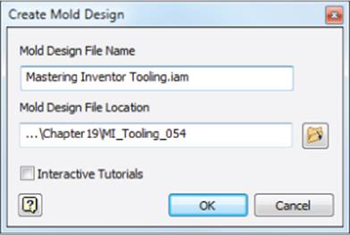
Two new tabs have been added to the ribbon: Mold Layout and Mold Assembly. Keep in mind that you may need to manually switch tabs to access certain tools at different times, depending on the tasks and the order in which you work. Other tabs will be created during the mold design process as well. Next, you'll import a plastic part to work with.
7. Click the Plastic Part button in the Mold Layout tab and select the file mi_19a_054.ipt. Then click Open to import the file, right-click and make sure the Align With Part Centroid option is selected, and then select Finish.
8. Select the Adjust Orientation tool from the Mold Layout panel. The preview of the Opening Direction will appear. Using the Flip button in the dialog box, flip the Z direction of the part so your preview looks like Figure 19.21.
9. Click the OK button when the direction has been properly set.
10.Click the Select Material button from the Mold Layout panel and change the manufacturer to BASF and the Trade Name to Terluran GP-22; then click the OK button.
11.Rotate the model so you can see the bottom of the part.
12.On the Runners And Channels panel, click the flyout under the Auto Runner Sketch button and select the Manual Sketch button.
13.In the resulting dialog box, ensure that the Runner Sketch option is selected and select the bottommost face on the part, as shown in Figure 19.22. Click the OK button to create the sketch.
14.Use the Project Geometry tool to project the x-axis (in the Origin folder) and the leftmost edge of the part into your sketch; then draw a line segment along the x-axis 13 mm long and 6 mm from the left edge of the part, as shown in Figure 19.23.
15.When the line is complete, right-click and choose Finish 2D Sketch; then right-click again and choose Finish Edit to return to the Mold Layout tools.
16.Save your work, and you will notice that a number of components are being created. Note too that these files are being saved in the mold design directory you created.
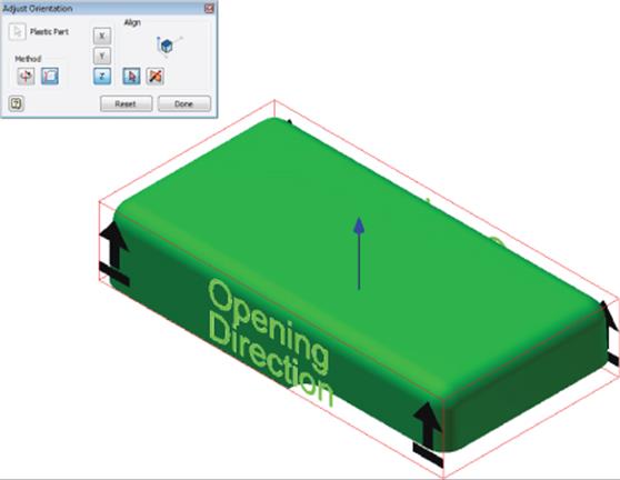
Figure 19.21 Setting the opening direction
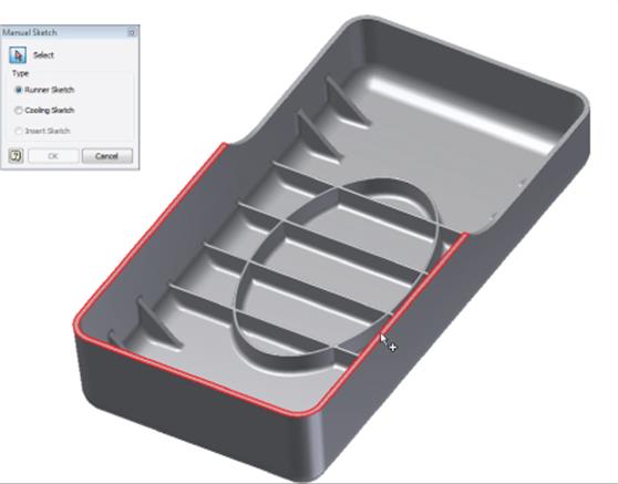
Figure 19.22 Creating a runner sketch
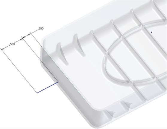
Figure 19.23 Dimensioning the runner
In this case you've created the runner sketch before creating and calculating the core and cavity. Although you are not required to work in this order, it can help to visualize how the runner and gate material will appear attached to the part when it drops from the mold. This is the approach you will take for the next exercises. You can close the file you have open and continue on to explore the creation of runners and gates.
Creating Runners and Gates
Now you will place the runner and gate. To continue, open the file mi_19a_056.iam from the Chapter 19 directory of your Mastering Inventor 2015 folder. This file picks up where you left off in the previous exercise:
1. On the Runners And Channels panel, click the Runner button to open the Create Runner dialog box.
2. Set Section Type to U Shape.
3. Use the radio button to set the runner to be created on the cavity side.
4. Set the radius to 3 mm.
5. Select the 13 mm sketched line for the path selection. Be sure to select it on the end farthest from the part. Selecting the line toward the other end creates the runner turned in the opposite direction. If you select the wrong end, just hold the Ctrl key and click it again to deselect it; then try again.
6. For Segment1, set the Cold Slug Length to 4 mm.
7. Check your settings against Figure 19.24 and then click the OK button to create the runner.
If you expand the Runner node in the browser, you will see your runner and runner sketch listed. You can double-click or right-click them to edit if changes are required. Next, you'll get ready to add a gate.
8. In the Runners And Channels panel, click the Gate Location button.
9. Select the bottom-left edge of the part. This is the edge with a sketch line running along it from the runner sketch. You can also use the ViewCube to verify the edge location where the left and bottom views intersect.
10.A ratio will appear in the dialog box. Set this to 0.5, meaning the gate will be placed halfway along the length of the edge. The preview should show an X at the intersection of the runner sketch lines.
11.Click Apply to create the gate location and then click Done to close the dialog box.
Now you will add the gate. There are a lot of options, so this will take several steps.
12.Click the Gate button to open the Create Gate dialog box.
13.Ensure that Type is set to Edge and then set the Up/Down radio button to Up.
14.Set Placement to Two Points. Inventor will start looking for the gate location.
15.Select the work point that displays the gate location you previously defined.
16.Once the work point is selected, Inventor will want the endpoint. Select the end of the runner sketch nearest to the part (this correlates to the 6 mm offset dimension).
17.In the dialog box, set the value of W1 to 22.
18.Set H1 to 12.
19.Set W2 to 15.
20.Set H2 to 6 and compare your inputs to Figure 19.25.
21.Click the OK button to create the gate when everything appears correct.
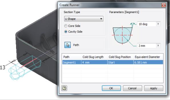
Figure 19.24 Placing the runner
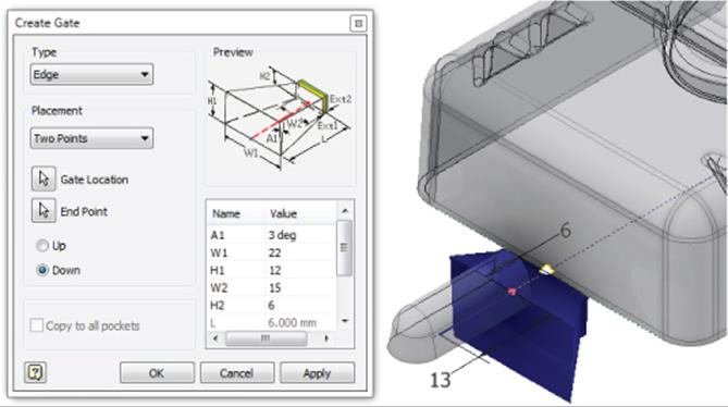
Figure 19.25 Placing the gate between the part and runner
In the previous steps, you explored the creation of runner and gate features. Although these features have many variations, the basic selections and steps to create them are the same. You can close the current file without saving changes and continue to the next section, where you will explore core and cavity design.
Analyzing and Creating Cores and Cavities
Now that you have defined your part's material and how you want the plastic to flow into the mold, the next step is to begin defining the mold itself. Keep in mind that all of the geometry you've been working on so far will become a void in the components you are about to create.
The tools needed to determine whether the part will fill properly and to establish the geometry of the core and cavity are more automated than other tools in Inventor. These tools will also inform you if you have missed a step in the process. Here is a brief overview of some of them:
1. Part Process Settings Optimal values for the mold temperature and pressures are loaded from the material information. This dialog box allows you to make modifications to accommodate your equipment if need be.
2. Part Fill Analysis Inventor Tooling has the ability to analyze the fill time, quality, and other important considerations regarding where weld lines may appear or air traps may occur.
3. Define Workpiece Setting Establishing the size of the tool from which your core and cavity will be cut is an important step. You must accommodate the runner and eventually the components of the assembly that move the material to the cavity.
4. Create Runoff Surface A runoff surface can be seen as an extension of the parting line. It is the surface that will be used to divide the workpiece so the parts of the mold can separate.
5. Generate Core And Cavity This tool launches you into another environment that is focused on how the workpiece will be modified to create the void for the plastic to fill.
To continue, open the file mi_19a_057.iam from the Chapter 19 directory of your Mastering Inventor 2015 folder. This file picks up where you left off in the previous exercise. To create the core, cavity, and other components, you will first need to change the environment in which you are working:
1. On the Mold Layout panel, click the Core And Cavity button. This brings up the Core/Cavity tab, which gives you access to the tools needed to create the workpiece that will be added to the mold base to complete the design.
2. Select the Gate Location button on the Plastic Part panel to place the gate in the workpiece. Note that these steps will be the same as those you followed in the previous exercise.
3. Select the bottom-left edge of the part near the visible work point.
4. Set the ratio to 0.5 to place the gate halfway along the length of the edge.
5. Click the Apply button to create the gate location and then click Yes when warned about the existing analysis results. Then click Done to close the dialog box.
6. Select the Part Process Settings button from the Plastic Part panel. Review the settings and then click the OK button to accept the default and close the dialog box.
7. Select the Part Fill Analysis button from the Plastic Part panel. Understand that this analysis may take some time to run, so if you prefer, you can just click Close and skip this step. If you'd like to run an analysis yourself, click Start and then click the OK button in the message box letting you know that the analysis is running.
8. When the analysis is complete, a summary showing the results will appear. If you skipped the previous step, you can view a previously prepared results summary. To do so, expand the node for mi_19a_054 in the browser and then expand the Results node and then the Fill node. Click the Summary node to bring up the results summary.
In Figure 19.26, you can see that the part can be filled, but there is concern about the quality obtained from the current setup.
9. Click Cancel to close the summary.
10.Double-click Fill Time in the browser to display the graphic in the design window (Figure 19.27).
11.Select the Define Workpiece Setting button on the Parting Design panel and set the following values, as shown in the lower right of Figure 19.28:
· X_Total value to 150
· Y_Total value to 75
· Z_Total value to 30
12.Click the OK button to preview the workpiece in the design window.
13.Select the Create Runoff Surface button on the Parting Design panel.
14.In the upper-left corner of the Create Runoff Surface dialog box, select the Auto Detect button to allow Inventor to search for the best parting line and create the runoff surface. The result should appear similar to Figure 19.29.
15.Click the OK button to create the parting surface that will divide the core and cavity.
16.Click the Generate Core And Cavity button on the Parting Design panel.
17.In the resulting dialog box, click the Preview/Diagnose button. This will preview the core in blue and the cavity in green.
18.Drag the Body Separation slider to the right and back to show how the parts will separate.
19.Click the OK button to generate the two parts.
On occasion, the runner and gate information created beforehand does not update with the generation of the core and cavity. Select the Mold Update tool from the Quick Access bar to bring this data up into the cavity side of the workpiece.
20.Click the Finish Core/Cavity button at the end of the ribbon to return to the Mold Layout tools and compare your work to Figure 19.30. You can close this file without saving changes and continue to the next section.
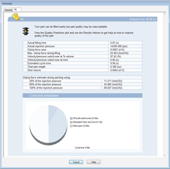
Figure 19.26 Part fill analysis summary
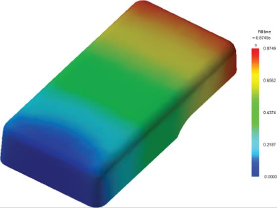
Figure 19.27 Fill time analysis results
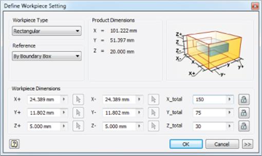
Figure 19.28 Setting the workpiece size values
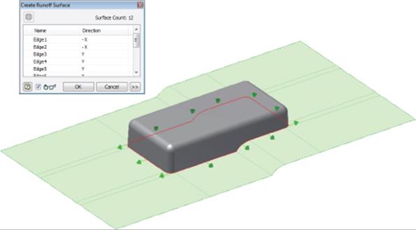
Figure 19.29 Generating the runoff surface for splitting the mold
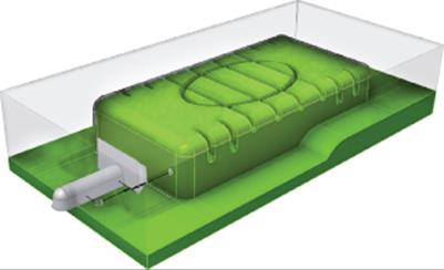
Figure 19.30 The completed workpiece
Working with Mold Bases
Now that the workpiece is complete, you can focus on generating the rest of the mold. These tools are located on the Mold Assembly tab. The tools in this tab are focused on the tools needed by manufacturing to generate the part efficiently. Inventor Tooling contains tens of thousands of parts for mold bases, as defined by the manufacturers. This works like a design accelerator to keep you from specifying something that will be a custom order or an inaccurate component. In the following exercise, you will focus on creating a mold base.
You will now build the entire mold base in just a few steps with minimal input and effort. This is a great example of how the functional design approach can work for you. To get started, open the file mi_19a_059.iam from the Chapter 19 directory of your Mastering Inventor 2015 folder and then follow these steps:
1. Switch to the Mold Assembly tab on the ribbon.
2. Click the Mold Base button in the Mold Assembly panel to open the Mold Base dialog box.
3. The Mold Base dialog box allows you to select from a huge library of standard mold base designs and to select options within those base designs. The following steps use items from the Content Center Mold database. To ensure that you can access these files, check your project and make sure the libraries are loaded. You can do so by selecting the Projects button on the Get Started tab, clicking the Configure Content Center Libraries button (in the lower-right corner), and selecting the Inventor Mold libraries.
4. From the Vendor And Type drop-down, select the DME; then click the Query button and select the type E base. Note that if you have previously selected the Immediately Query check box, you will not need to click the Query button.
5. Set the size to 346 mm × 346 mm.
6. Expand the dialog box by clicking the double-arrow icons on the top- or bottom-right edge of the dialog box.
7. Expanding the dialog box will show the list of components included in the mold base.
8. Select the part labeled E 400 346X346X76.
9. Once the part is selected, several buttons appear for that row. Select the button with the ellipsis (three dots; the tool tip will say Property Settings). This will launch a dialog box for changing options (if any exist).
10.Click the H_value and change it in the drop-down list from 76 mm to 56 mm, as shown in Figure 19.31.
11.Click the OK button to close the dialog box. Inventor will update the E400 plate's description and the preview in the dialog box.
12.Click the Placement Reference button and select the bottom point in the front-left corner of the workpiece (use the ViewCube for reference to find the left and front sides).
13.You will see a preview outline of where the mold base will be positioned around the workpiece. Make sure the workpiece appears inside the rectangle.
14.Once you've verified that the workpiece appears inside the rectangle, click the OK button in the dialog box to generate the mold base.
15.If the Mold Update button becomes visible in the Quick Access bar, click it and compare your work to Figure 19.32.
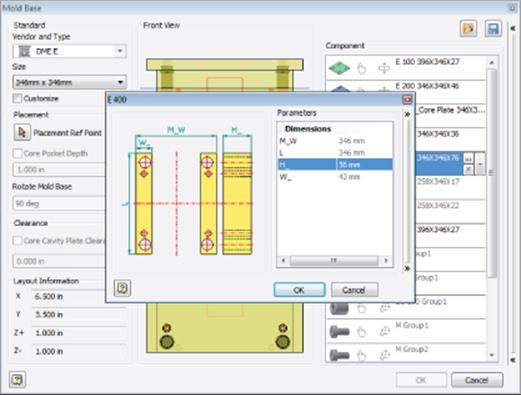
Figure 19.31 Changing the mold-base components
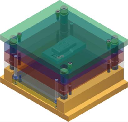
Figure 19.32 The mold base after placement
You may not have been expecting the entire mold base to be generated, but since the components are purchased, it makes sense to place them as a unit as they would be assembled. You can close this file without saving changes and continue to the next section.
Working with Ejectors and Sprue Bushings
You will now complete one last series of steps to see the final critical details of placing ejectors and the sprue bushing:
1. Ejector Accessing the library of standard ejector pins is only part of this tool. It will make it easy for you to properly align the pins based on the center of the component, using a coordinate system that is used by the toolmakers.
2. Sprue Bushing This tool places the standard sprue bushing based on the location of the runner, simplifying the process of placement and improving the quality.
To get started, open the file mi_19a_059.iam from the Chapter 19 directory of your Mastering Inventor 2015 folder. Then follow these steps:
1. On the Mold Assembly tab, select the Ejector button.
Doing so clears the screen of everything but the original part and runoff surface. It also opens the Ejector dialog box, which contains standard ejector pins and their optional sizes.
2. Leaving the options at the default, click the plastic part to place four ejectors. You can choose four approximate locations between the pairs of ribs, as shown in Figure 19.33.
3. Click the ![]() button in the dialog box and set the values to 33 mm or −33 mm for the X column and 17 mm or −17 mm for the Y column.
button in the dialog box and set the values to 33 mm or −33 mm for the X column and 17 mm or −17 mm for the Y column.
The order in which you placed your ejectors might cause your positive or negative values to differ, but entering the inputs as shown will give you the correct result.
4. Set the diameter (d1 value) to 2 mm and the length (L value) to 100 mm and then click the OK button to place the ejectors in the mold.
Placing the ejector will cause Inventor to make clearance cuts in other plates and cut the length or even the contour of the ejector to prepare all of the components in the mold base. Select any of the pins in the browser to show how they terminate at the core face of the mold.
Next, you'll place a sprue bushing and a locking ring.
5. On the Mold Assembly tab, click the Sprue Bushing button. It will be looking for a point from which to locate.
6. Select the visible sketch center point at the end of the runner sketch farthest from the part.
7. Set Type to DME AGN.
8. Set the length (L value) in the dialog box to 76 mm using the drop-down.
9. For an offset value, enter −14 mm.
10.Click the OK button to place the bushing and cut the clearance geometry in the relevant parts.
11.Select Sprue Bushing in the Design window.
12.Right-click and select Open from the context menu.
13.Rotate the part to see how the runner geometry has been cut from the bushing, as shown in Figure 19.34.
14.To return to the assembly, close the Sprue Bushing part and do not save changes.
15.Click the Locating Ring button from the Mold Assembly panel.
16.Set the type to Rabourdin 646-Type B and choose the top of the base face (green plate).
17.Set the D2 value to 32 mm and the A_ value to 22.5 mm and then set the offset value to −22.5 mm.
18.Click the OK button to place the ring into the assembly.
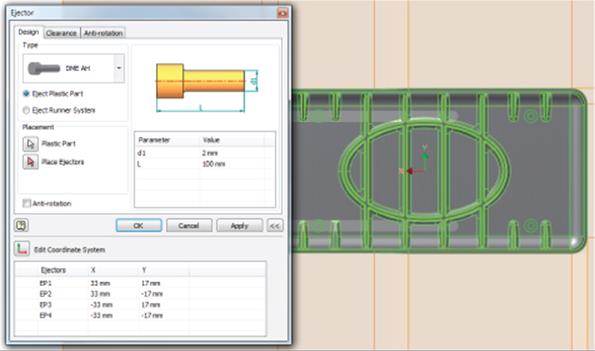
Figure 19.33 Placing the ejectors
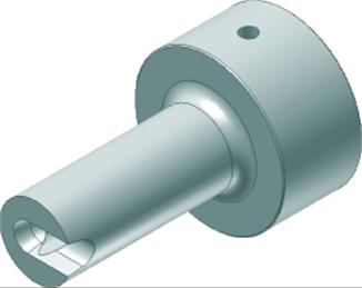
Figure 19.34 The runner geometry is cut into the sprue bushing
The finished base should look like Figure 19.35.
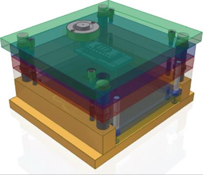
Figure 19.35 The finished base
Through use of functional design techniques, the most tedious steps of designing a mold are eliminated or greatly simplified. You can close this file without saving changes, explore the Inventor Tooling tools with your own design, and take advantage of just how easy it is to create a complex mold design.
You can also find additional mold and tooling tutorials built right into Inventor by clicking the Tutorials button on the Get Started tab.
The Bottom Line
1. Create thicken/offset features. When creating plastic parts, you will often find that working with surfaces allows you to achieve more free-form shapes than working with solids. Once the surfaces are created, you'll need to give them a thin wall thickness.
1. Master It How would you create a plastic part file with many curved, free-form elements?
2. Create shell features. Shelling solids parts and features is a common way to create base features for plastic parts. Once the shell feature is created, other features can be added to it.
1. Master It You want to create a shell feature but need to have some faces be thicker than the rest. How would you accomplish this?
3. Create split features. Many times you may want to establish the overall shape of a feature and then divide the shape into separate parts of the overall design. You can use the Split tool to do just that and more.
1. Master It You have a plastic part that needs to have a raised face for a rubber grip applied during the manufacturing process. How would this be done?
4. Create grill features. Grill features allow the inflow or outflow of air through a plastic thin-wall part. Grills can be created with a number of subfeatures such as islands, ribs, and spars, but only the outer profile of the grill is required.
1. Master It How would you determine the area of a grill opening based on the airflow it needs to handle?
5. Create rule fillet features. Rule fillets can be an extremely efficient way to apply fillets throughout the design to many edges that meet the same rule criteria.
1. Master It How would you apply fillets to all of the edges that are generated by extruding a shape down to an existing set of base features?
6. Create rest features. Rest features can be used to create level platform faces for mounting other parts to an irregular plastic part face.
1. Master It You want to create a rectangular pocket on the inside of a plastic housing to hold an electronic component. How would you do this?
7. Create boss features. Boss features are ideal for creating fastener-mounting standoffs for thin-wall plastic parts. You can use the Boss tool to create both halves of the fastener boss.
1. Master It You want to create multiple boss features around the perimeter of a flat, pan-type base part, but you know this base part is likely to change size. How would you set up the boss features to adjust to the anticipated edits?
8. Create lip and groove features. When designing plastic parts, you may need one half of a design to fit into the other half. The Lip tool allows you to create both lip and groove features for these situations.
1. Master It You want to create a groove around the edge of an irregular, curved edge. How can you ensure that the lip on the corresponding part will match?
9. Create snap fit features. Snap features are a common way to join plastic parts together so that they can be disassembled as needed. You can use the Snap Fit tool in Inventor to quickly create these features.
1. Master It How would you create a U-shaped snap fit with the Snap Fit tool?
10.Create rib and web features. Ribs and webs are often used to add rigidity and prevent warping during the design of plastic parts. You can add ribs based on open profile sketches in Inventor.
1. Master It How would you create a network of ribs that are evenly spaced, with some of them containing different cutouts than others?
11.Create draft features. Because plastic parts must be extracted from a mold during the manufacturing process, drafted faces must be included to ensure that the parts can indeed be extracted from the mold.
1. Master It You want to create drafted faces on a complex part containing various shapes within it. How would you do this?
12.Create an injection mold. To generate the components you have designed with the plastic part features, you need to properly define the cavity to create the part and define how the material will flow into the cavity.
1. Master It You want to create a mold base design in an efficient manner using parts that can be purchased.