Mastering Autodesk Inventor 2015 and Autodesk Inventor LT 2015 (2014)
Chapter 3. Sketch Techniques
This chapter will cover the principles of creating parametric sketches used in part modeling within the Autodesk® Inventor® and Autodesk® Inventor LT™ programs. All the skills discussed in this chapter are based primarily on creating a single part, whether in a single-part file or in the context of an assembly file.
Inventor utilizes two types of sketches: a 2D sketch and a 3D sketch. A 2D sketch is created on any geometry plane and is the more common of the two types. A 3D sketch is not limited to a sketch plane and can comprise geometry in any point in space. 3D sketches are often created from existing geometry. Both 2D and 3D sketches are controlled by two basic parameter types: dimensions and sketch constraints.
In Inventor, sketches are generally “roughed out” with basic geometry and sketch constraints first and then fully defined with dimensions that drive the geometry.
The dimensions dictate the length, size, and angle of the sketch geometry. For the dimensions to do this predictably, sketch objects must know how to interact with one another. This interaction is defined by the sketch constraints. This chapter will cover how to create part features using basic 2D and 3D sketches, including the tools and settings that govern their creation. Also covered is how to use Autodesk® AutoCAD® data to create sketches.
In this chapter, you'll learn to
· Set up options and settings for the sketch environment
· Create a sketch from a part file template
· Use sketch constraints to control sketch geometry
· Master general sketch tools
· Create sketches from AutoCAD geometry
· Use 3D sketch tools
Exploring the Options and Settings for Sketches
Before you jump into creating a part sketch, take a look at the options and settings Inventor provides for sketches. Options and settings in part files are located in two different areas of Inventor, depending on whether the focus of these settings affects the application (Inventor) or the document (your part file). You'll look at both application options and document options in the following sections.
If you have not already downloaded the Chapter 3 files from www.sybex.com/go/masteringinventor2015, please refer to the “What You Will Need” section of the introduction for the download and setup instructions.
Application Options
In this section you'll explore the options and settings found in the application options collection. Application options change settings for your installation of Inventor. You can adjust the application settings as follows:
1. From the Tools tab, click the Application Options button.
2. Choose the Sketch tab, as shown in Figure 3.1.
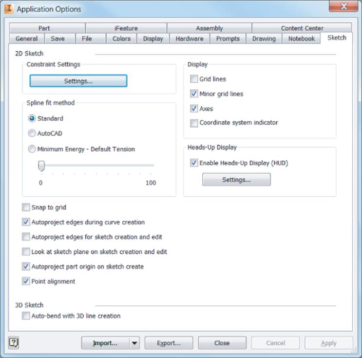
Figure 3.1 Sketch tab of Application Options dialog box
The application options on the Sketch tab are as follows:
1. Constraint Settings Area The options in this section determine the method and options involved in creating and managing 2D sketch constraints. When you click the Settings buttons, you are presented with the Constraint Settings dialog box. Note that the constraint settings can also be accessed by selecting the Constraint Settings button on the Constrain panel of the Sketch tab. There are three tabs found in this dialog box:
1. General Use these options to set default display and behaviors for sketch constraints and dimensions. Figure 3.2 shows the General settings tab.
2. Inference Use these options to set default behaviors for inferred or automatically placed sketch constraints. Figure 3.3 shows the sketch inference settings.
3. Relax Mode With the Enable Relax Mode options selected, conflicting sketch constraints are removed when you add new constraints or dimensions. Essentially this allows the last constraint placed to “win” in instances where placing a new sketch constraint conflicts with an existing sketch constraint. Figure 3.4 shows the Relax Mode tab settings.
2. Display Area Located in the upper-right portion of the Sketch tab, this area gives you settings for grid lines, minor grid lines, axes, and a 2D coordinate system indicator. All of these options set different visual references in the form of grid lines and coordinate indicators. You can experiment with these settings by deselecting the box next to each option and clicking the Apply button while in sketch mode.
3. Spline Fit Method Area This determines the initial type of transition for a spline between fit points. Figure 3.5 shows two splines drawn with the same input points. On the left, the standard spline solution is in bold with the AutoCAD solution dashed; on the right, the standard solution is dashed with the AutoCAD solution in bold.
1. Standard Creates a spline with a smooth continuity (G3 minimum) between points. This spline type tends to overshoot at sharp transitions. Use this for Class A surfaces such as automotive design.
2. AutoCAD Creates a spline using the AutoCAD fit method (G2 minimum). This is not used for Class A surfaces.
3. Minimum Energy Sets the fit method to create a spline with smooth continuity (G3 minimum) and good curvature distribution. Multiple internal points are used between fit points, resulting in a nice, heavy curvature. This can also be used for Class A surfaces, but it takes the longest to calculate and creates the largest file size.
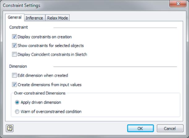
Figure 3.2 Constraint settings dialog box
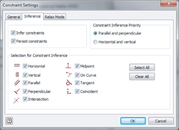
Figure 3.3 Sketch inference settings
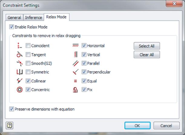
Figure 3.4 Constraint relax mode
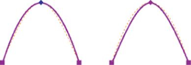
Figure 3.5 Standard spline fit (left) and AutoCAD spline fit (right)
About Curve Classification
Curves are classified by how smooth the continuity is where they connect to one another. This classification is as follows:
· G0 controls the position at which curves touch one another.
· G1 controls the tangent angle at which curves connect.
· G2 controls the radius at which curves connect.
· G3 controls the acceleration or rate of change of curves.
1. Snap To Grid Check Box This allows your mouse pointer to snap to a predefined grid spacing. The grid spacing is controlled per file in the document settings, as will be discussed in the coming pages.
2. Autoproject Edges During Curve Creation Check Box This allows you to reference existing geometry from your sketch plane and have that geometry automatically included in your sketch. For example, if you sketch on the top face of a part that has a hole on the bottom face, you might want to find the center of the hole to reference in your sketch, but since that hole exists on a different plane, it needs to be projected up into your current sketch before you can do so. Enabling this option allows you to “rub” your mouse over the hole and have it automatically projected into your sketch. Figure 3.6 shows a line being sketched from the middle of the cylinder to the center of a hole on the bottom face. With this option on, simply rubbing the edge of the hole will project it to the top face so that the line can be sketched to the center of the projected circle. This option can be toggled on and off by selecting AutoProject in the context menu of most of your sketch tools, such as Line, Circle, Arc, and so on.
3. Autoproject Edges For Sketch Creation And Edit Check Box This automatically projects the edges of the face when you create a sketch on it. Although this ability can be convenient in some cases, it can also become counterproductive because it places extra line work into your sketches. This can add a level of complexity to your sketches that is not required. Figure 3.7 shows the results of selecting this option on the left and of having this option unselected on the right.
4. Look At Sketch Plane On Sketch Creation Check Box This reorients the graphics window so that your view is always perpendicular to the sketch plan while you are creating or editing a sketch.
5. Autoproject Part Origin On Sketch Create Check Box This automatically projects the part's origin center point whenever a new sketch is created. The origin center point is point 0 in the X, Y, and Z directions. Projection of this point makes it easy to constrain and anchor your sketch. If this option is not selected, you are required to manually project this point.
6. Point Alignment On Check Box This allows endpoints and midpoints to be inferred by displaying temporary, dotted lines to assist in lining up sketch entities. Figure 3.8 shows an endpoint being located using the Point Alignment On option.
7. 
Enable Heads-Up Display (HUD) Check BoxThis allows you to input numeric and angular values directly into input boxes when creating sketch entities. For instance, if you were to sketch a circle without HUD on, you'd rough in the approximate size and then use the Dimension tool to give the circle an exact diameter. With HUD, you can specify the diameter as you create the circle. Clicking the Settings button opens the Heads-Up Display Settings dialog box, where you can adjust the HUD settings.
8. Auto-Bend With 3D Line Creation Check Box This allows corners to be automatically rounded when you're creating a 3D sketch. This feature can be turned on and off via the context menu when using the Line tool in a 3D sketch. Figure 3.9 shows corners created without the auto-bend feature enabled. The default auto-bend radius size is set per file via the document settings but can be edited once the bends are created.
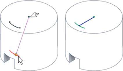
Figure 3.6 Autoprojecting a hole edge while sketching on the top face
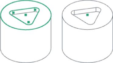
Figure 3.7 Results of the Autoproject Edges For Sketch Creation And Edit check box

Figure 3.8 Point alignment inferring endpoint
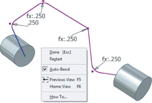
Figure 3.9 A 3D sketch line with Auto-Bend With 3D Line Creation
To set changes made to the application options, you can click the Apply button. You can save the changes you make to the application options for backup or distribution among other users by clicking the Export button at the bottom of the Application Options dialog box. In the resulting Save Copy As dialog box, simply specify the name of the XML file and click OK. You can import this XML file at any time to restore your custom settings by using the Import button at the bottom of the Application Options dialog box.
Document Settings
In addition to the previous settings, which are set application-wide, there are settings that control options per file. Document settings vary depending on the file type you are in. For part files, you can modify the sketch settings by clicking the Document Settings button on the Tools tab of the Ribbon menu while you are in an open part file. Once the Document Settings dialog box is open, click the Sketch tab to access the following settings:
1. Snap Spacing This sets the spacing between snap points to control the snap precision when you're sketching in the active part or drawing. This is relevant only when using the Snap To Grid option on the Sketch tab of the Application Options dialog box. The settings for the x- and y-axes can be different.
2. Grid Display This sets the spacing of lines in the grid display for the active file.
3. Line Weight Display Options These set the options for line weight display in the sketch environment. This setting does not affect line weights in printed model sketches, just the on-screen display.
4. Auto-Bend Radius This sets the default radius for 3D sketch line corners when the auto-bend feature is used.
You may want to configure the document settings in a template file and then save those settings back to that file so they are always set to your specification. To do so, click the Inventor button at the top-left corner of the screen and select Save As ![]() Save Copy As Template. This will open the template file location and allow you to save the file as a template. Note that Inventor uses the template path to designate templates rather than using the filename extension. Therefore, any IPT file saved under the template path is considered a template.
Save Copy As Template. This will open the template file location and allow you to save the file as a template. Note that Inventor uses the template path to designate templates rather than using the filename extension. Therefore, any IPT file saved under the template path is considered a template.
Changing the Units of a Part File
If you start a part file using the wrong template (inches instead of millimeters or millimeters instead of inches), you can change the base units of the file by clicking the Document Settings button on the Tools tab of the Ribbon menu and selecting the Units tab. Changing the base units will automatically convert parameters but will not override parameter inputs. For instance, if you enter a value of 3 inches for a dimension and then change the units of the file to millimeters, the dimension will show 76.2 mm; however, when you edit the dimension, you will see the original value of 3 inches.
Sketching Basics
Now that you've explored the sketch options and settings, you will explore the sketching tools by placing sketches on an existing 3D part. This will give you an introduction to creating 2D sketches in 3D space. The basic workflow for creating any 2D sketch is as follows:
1. Establish the plane on which you want to sketch.
2. Project geometry from an existing feature to position new geometry.
3. Create geometry such as lines, arcs, circles, and so on.
4. Place sketch constraints on the geometry so the lines, arcs, and circles know how to relate to one another.
5. Dimension the geometry so it is fully defined and there is no part of the sketch that can be accidentally adjusted.
Marking Menus
Throughout this chapter, you will be instructed to right-click and select certain options as needed. If you have the marking menus enabled, some of the right-click options might vary, such as in exact placement of the option. Therefore, you should be prepared to interpret the instructions to what you see on-screen if you prefer to use the marking menus. If you prefer to have options in this chapter's exercises match exactly what you see on-screen, you can disable the marking menus and use the classic right-click context menu. This can be done by selecting the Tools tab and clicking the Customize button. On the Marking Menu tab, you will find an option called Use Classic Context Menu.
Keep this workflow in mind as you go through the following steps and explore the basics of sketch creation. To get started, you will open an existing file and sketch on the faces of the part.
Creating a Sketch on an Existing Sketch
1. From the Get Started tab, choose Open (or press Ctrl+O on the keyboard).
2. Browse for the file mi_3a_001.ipt in the Chapter 3 directory of your Mastering Inventor 2015 folder and click Open.
This file consists of a stepped block with one beige face, one face with two holes in it, and one face with a triangular feature on it. To start, you will create a sketch on the top, beige face. Before getting started, set your application options so you will not see any unexpected results as you follow these steps:
3. From the Tools tab, click the Application Options button.
4. In the Application Options dialog box, click the Sketch tab.
5. In the Sketch tab, ensure that all the check boxes are set as shown in Figure 3.10.
6. Click Apply and then click Close to set your sketch options, and close the Application Options dialog box.
7. Hover your cursor over the ViewCube® until you see the Home button (it looks like a house) and then click it to make sure you are looking at the model from the predefined home view.
8. From the 3D Model tab, click the Start 2D Sketch button.
To create a 2D sketch, you must select a plane to sketch on, as indicated by the glyph now present at your cursor (it looks like a pencil and paper). You should also note the input prompt found either at the bottom left of your screen or at your mouse pointer, depending on the Dynamic Prompting settings you have active.
9. Click the top, beige face to create the new sketch on it.
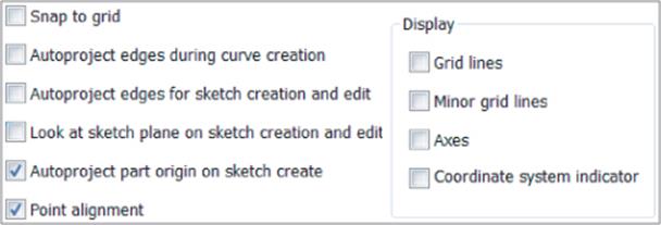
Figure 3.10 Setting sketch options
Turn on Dynamic Prompting
As you use the various available tools, Inventor will prompt you with a short message concerning the input needed from you to complete a task. By default, the prompts are displayed at the lower left of the screen. To help you notice them better, you can set them to display on-screen at your cursor. To do so, on the Tools tab, click Application Options. Select the General tab, select the Show Command Prompting (Dynamic Prompts) check box, then click Apply, and finally click Close.
Once you've selected the face, you'll notice the change in the tools displayed on the Ribbon menu and the activation of the Sketch tab. You should also notice that the browser has grayed out all of the other features and only the new sketch (it should be named Sketch6) is active, as shown in Figure 3.11.
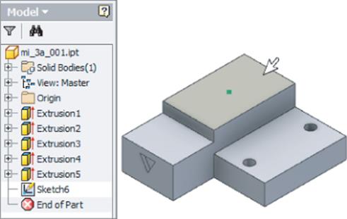
Figure 3.11 Creating a new sketch
Projecting Geometry into Your Sketch
You'll also notice that a sketch point (a small dot in the center of the beige face) has been automatically created. This is the 0,0,0 origin point of the part. It has been automatically projected into your sketch because of the Autoproject Part Origin On Sketch Create setting, as shown in Figure 3.10. Next, you'll continue with the file you've been working with and project geometry into your sketch.
1. Select the Project Geometry tool from the Sketch tab and then click somewhere in the middle of the beige face. You will now see the rectangular edges of the beige face displayed as sketch lines.
2. Right-click and choose OK or Cancel to exit the Project Geometry tool (or press the Esc key on the keyboard).
3. In the browser, click the plus sign next to the Sketch6 browser node. You will see a projected loop listed under the sketch, as shown in Figure 3.12.
The projected loop consists of lines that trace the outer edges of the beige face. These lines were created by projecting the beige face into your sketch. These projected sketch lines are currently locked in place to always remain associative to the face from which they were created. In the next step, you will break the associative link between the projected edges and the face.
4. Right-click the projected loop in the browser and choose Break Link, as shown in Figure 3.13.
When you break the link, the projected loop node disappears in the browser, and the projected lines around the beige face change color. The color change indicates that the sketch lines are no longer associated with the face.
If you click and drag any of the projected lines, you'll notice that they can be dragged around anywhere in the sketch plane. Because the sketch plane extends past the beige face, the lines can be dragged out even beyond the extents of the face. A 2D sketch stretches out infinitely in the two directions that make up the plane. Next you'll clean up the projected lines and project more lines.
5. Hold down the Ctrl key on the keyboard and select all four of the lines. Notice the color change indicating the selection status of the lines. If you want to remove a line from the current set of selected objects, you can click it again while holding the Ctrl key. To add it back, you would click it again, still holding the Ctrl key.
6. With all four lines selected, right-click and choose Delete.
7. Select the Project Geometry tool again, and this time, select just the circular edges of the two holes found on the lower step of the part.
Watch the color-coded selection closely to ensure that you are getting just the hole edges and not the entire face the holes are on. If you choose the entire face, you will get the four rectangular edges as well as the two hole edges, and a projected loop will be created under the sketch in the browser. If you do accidentally select the face, use the Undo button on the Quick Access bar and then repeat step 7.
Since you selected just the circular edges, there is no projected loop created. However, the circles are still created so that they are associative to the holes from which they were created. This means that if the original holes change locations or diameter, the projected circles will adjust accordingly.
Another point to note is that when you project the edges of the holes into your sketch, they are projected up onto the sketch plane even though the holes are at a lower elevation. To see this clearly, you can use the ViewCube to adjust your viewing angle.

8. Click the face of the ViewCube labeled Front, and you will be able to see that the projected hole edges are in the same plane as the beige face on which you created your sketch.
9. Click the Home button on the ViewCube to set your view back to the home view.
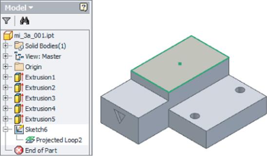
Figure 3.12 A projected sketch loop
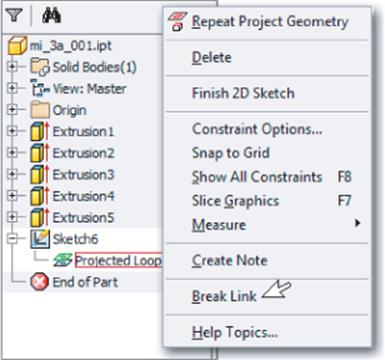
Figure 3.13 Break link for a projected loop
Breaking Links to Projected Geometry
Next, you'll continue working with the same file and will break the link with the projected circles and the holes from which they were created. Since no projected loop was created when you projected just the edges, there is no projected loop node listed under the Sketch node in the browser. Projected loops are created only when faces are selected. Instead, you will break the link by selecting the circles in the graphics area:
1. Right-click one of the circles and choose Break Link from the context menu. The circle will change color, indicating it is no longer associative to the hole and, therefore, no longer constrained in place.
2. Click the nonassociative circle and notice that you can resize it by clicking and dragging the circle itself, and you can move the circle by dragging the center point.
Deleting a Sketch
In the next steps, you will exit the current sketch and then delete the entire sketch. Deleting sketches from the browser is a common task, and understanding how to remove unneeded sketches is an important concept in learning how to manage sketches in the Model browser. Follow these steps, using the same file you've been using:
1. Click the Finish Sketch button on the Sketch tab (or right-click and choose Finish 2D Sketch). Notice that the Sketch node is no longer highlighted in the browser and the Sketch tab has disappeared, leaving the 3D Model tab active.
2. Right-click the Sketch6 node in the browser and choose Delete. You will notice that the Sketch node is removed from the browser and, therefore, the projected circles are removed from the graphics area.
Creating Another New Sketch
Next, you'll create a new sketch on the face with the triangular cut in it. Rather than using the Start 2D Sketch button as you did before, you will create the sketch through the context menu.
1. Right-click the face with the triangular cut in it and then choose New Sketch, as shown in Figure 3.14.
You will see the new Sketch node created in the browser, the Sketch tab appear in the Ribbon menu, and the projected origin point appear in the sketch (the dot in the center of the triangle).
2. Click the face labeled Front on the ViewCube to set your view perpendicular to the sketch plane.
3. Select the Circle tool from the Create panel of the Sketch tab.
4. 
Click to the left of the model to set the center of the circle and then drag out to draw the circle as shown in Figure 3.15. Then type 100 in the Heads-Up Display input box and press the Enter key on the keyboard to set the diameter. (If you do not see the Heads-Up Display input, check your settings against those shown in Figure 3.10.)
5. Select the Project Geometry tool from the Sketch tab and then select the face with the triangular cutout.
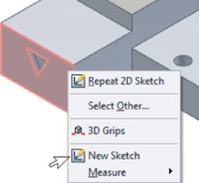
Figure 3.14 Creating a sketch from the context menu
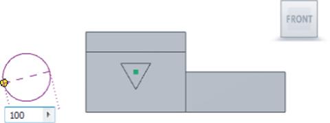
Figure 3.15 Placing a circle in the sketch
Creating Dimensions
You can use sketch dimensions to specify the size and position of your sketch entities. Keep in mind that Inventor's sketch dimensions are used to “drive” the sketched objects into shape and into position. Using dimensions in this way allows you to specify the intent of your design and manage it with dimensional parameters. Continue following these steps using the same file you've been working with:
1. Select the Dimension tool from the Sketch tab and then click the projected bottom point of the triangle and the center point of the circle. Drag your cursor down until you see the dimension.
2. Click the screen to set the dimension and then enter 150 into the input box; click the green check mark to apply the input.
You will see that the circle is “driven” into place and repositioned to be 150 mm from the point of the triangle. This is what is meant by a driving dimension. The circle's position is driven by the dimension.
3. With the Dimension tool still active, select the center point of the circle and then the horizontal line of the triangle and drag your cursor to the left until you see the dimension.
4. Click the screen to set the dimension and then enter 150 into the input box; click the green check mark to apply the input.
5. Right-click and choose Cancel to exit the Dimension tool.
At this point your sketch should be fully constrained, as noted in the lower right of the screen, and it should resemble Figure 3.16.
6. Use the Finish Sketch button to exit the sketch.
7. Click the Home button on the ViewCube to set your view back to the home view.
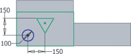
Figure 3.16 The circle dimensioned in the sketch
Edit Dimensions When Created
There is an option that controls the behavior related to the creation of new dimensions and the automatic display of the dimension edit box. If you go to the Tools tab on the Ribbon menu, click the Application Options button, and then select the Sketch tab, you will see a Settings button in the Constraint Settings area. When you click this button, you will find an Edit Dimension When Created check box in the Dimension area of the General tab. Typically this check box is selected.
This concludes the steps in this introductory exercise. You should now be familiar with the basics of creating sketches on existing part faces and projecting existing geometry, as well as deleting geometry and sketches. You can close the file without saving changes or experiment with this part and create more sketches just for fun.
As you create 2D sketches in Inventor, you will often do so by selecting a face on the existing model, as you did in this exercise. If no plane exists, you can create what is called a work plane and sketch on it (work planes will be covered in the next chapter). In the next section, you will create a new part from a template file and create a base sketch.
Creating a Sketch in a New Part
When you create a new part file from a template, Inventor can create the first sketch for you on one of the origin planes. You can also configure Inventor not to create the initial sketch and allow you to create it yourself. This option is set by going to the Tools tab and clicking the Applications Options button and then clicking the Part tab. In the following exercises, you will create a new part file and further explore the tools used to create sketch entities. To create a part model in Inventor, you will typically start with a 2D sketch and build a base feature from that sketch.
Creating a New Part File from a Template
You create new part files from an IPT template. Once you open the IPT template, you will automatically be in the sketch environment. In this exercise, you will use the Standard(mm).ipt file.
To explore sketch fundamentals in the next exercise, you should disable the HUD tools found on the Sketch tab of the Application Options dialog box. The HUD tools allow you to place dimensions as you create sketch geometry rather than having to go back and place dimensions later. Although the HUD tools are helpful and you will most likely want to turn them back on later, for the purpose of understanding sketch constraints and degrees of freedom, it is best to leave the dimensioning as a final step.
To disable the HUD tools, click Application Options on the Tools tab. Select the Sketch tab and uncheck the box labeled Enable Heads-Up Display (HUD). You can turn this helpful feature back on later, but understand that the following steps assume it is disabled and your results may not match the exercise otherwise.
To create a new file from a template, follow these steps:
1. From the Tools tab, click the Application Options button.
2. Select the Part tab and set the Sketch On New Part Creation option to Sketch On X-Y Plane; then click the OK button to close the Application Options dialog box.
3. From the Get Started tab, click the New button. This will bring up the list of templates in the New File dialog box.
4. In the New File dialog box, select Metric from the list on the left and then select the Standard(mm).ipt button (see Figure 3.17).
5. Click Create to create a new part file based on this template.
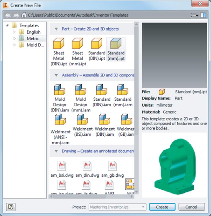
Figure 3.17 Templates on the Metric tab
Creating Lines Using the Line Tool
Your screen should now show the Sketch tab set active on the ribbon, and a sketch called Sketch1 has been created and set current in the Model browser. In the following steps, you will create simple geometry using the Line tool. These steps will focus on the creation of 2D sketch constraints as well:
1. Pause your mouse pointer over the Line tool in the Sketch tab's Create panel. (See Figure 3.18 for the location of the Line tool.)
2. Note the tool tip that appears, providing the tool name, keyboard shortcut (in this case L), and a brief description of the tool. If you hover the pointer over the tool long enough, a second stage of the tool tip appears with a more detailed description.
3. Click the Line button to start the Line tool.
4. Hover your mouse pointer over the dot in the center of the drawing area. This is the 0,0,0 origin point that has been automatically projected into Sketch1.
Note that when your mouse pointer moves over the dot, the dot changes to green and shows a small glyph symbol. This green dot is a snap symbol indicating that a point, endpoint, or midpoint has been located. The glyph symbol indicates that a sketch constraint is being placed. In this case, it is a Coincident constraint, which ensures that the endpoint of the line will stay coincident to the projected origin point. See Figure 3.19 for reference.
5. Start your line on this point by clicking the dot and releasing the mouse button.
6. Move your mouse pointer directly to the right, and you will see another glyph indicating that a Horizontal sketch constraint is being placed. The Horizontal constraint ensures that the line will stay positioned horizontally. Note that if you move your mouse pointer so that the line is being drawn at an angle, the glyph disappears.
Turning On the Projected Origin Point
If you do not see a sketch center point in your file, close the file and follow these steps to turn this option on:
1. 1. From the Get Started tab, select the Application Options tab.
2. 2. Choose the Sketch tab.
3. 3. Select the Autoproject Part Origin On Sketch Create check box.
4. 4. Click OK.
5. 5. Start a new file using the Standard(mm).ipt template.
7. Notice the status bar at the bottom of the screen indicating the length and angle of the line as you move the mouse pointer. Click the graphics window while the horizontal glyph is displayed to create a line roughly 45 mm long (the length is shown at the bottom right of the screen).
Don't worry about getting an exact length. You will set the precise length later; for now, you are just “roughing in” a general shape. Note that the line continues when the first line segment is placed, and you can add more segments as required.
Temporarily Displayed Constraint Glyphs
If you see a gray temporarily displayed horizontal constraint glyph above the line at this point, this is because of the setting found by going to the Tools tab, clicking the Applications button, clicking the Sketch tab, and then clicking the Settings button in the Constraint Settings area. On the General tab you'll see the Display Constraints On Creation option, which controls this.
8. Move your mouse pointer straight up to add another line segment, and note that another glyph appears at the mouse pointer. This is a perpendicular glyph indicating that a sketch constraint is being placed that will hold the first and second line segments perpendicular (see Figure 3.20 for reference).
9. Click the graphics window to create the second segment at roughly 45 mm long and perpendicular to the first segment.
10.Right-click and choose Cancel to exit the Line tool. Note that the Esc key will also exit the active tool, as indicated in the context menu.
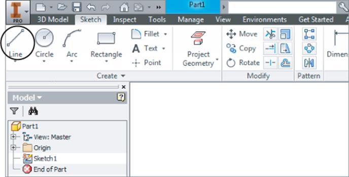
Figure 3.18 Locating the Line tool on the Sketch tab
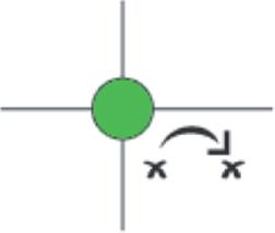
Figure 3.19 Endpoint snap symbol and coincident glyph
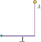
Figure 3.20 Creating a vertical line with an automatic Perpendicular constraint
You should now have a single horizontal line and a single vertical line making a backward L shape. If you made a mistake, simply use the Undo button at the top of the screen (or press Ctrl+Z) to undo and try again. Leave this file open for use in the next set of steps.
Understanding Sketch Constraints
The glyphs you were observing while creating the line segments were indicators that Inventor was placing sketch constraints automatically as you were sketching the lines. By default, the sketch constraints have their visibility turned off. To see the sketch constraints that are present and how they work, continue with the following steps:
1. Right-click anywhere in the graphics window other than on the lines and choose Show All Constraints (or press F8 on the keyboard). You will now see the Sketch Constraint icons for the constraints that were inferred as you created the line segments.
2. Hover your mouse pointer over the Perpendicular constraint at the corner of the two line segments to see both lines highlighted, which indicates that these are the objects involved in this particular constraint definition.
3. Hover your mouse pointer over the yellow dot at the corner of the two line segments, and you will see two Coincident constraints appear, as shown in Figure 3.21. Hovering your mouse pointer over each will highlight the line to which it belongs. Coincident constraints are initially “rolled up” in this way because they are generally numerous and tend to clutter the sketch when all constraints are shown.
When in Doubt, Right-Click
Inventor is very right-click-driven, meaning that often you can find the option you are looking for by right-clicking the object you are dealing with.
In Inventor, the right-click context menus are specific to the objects you have selected. If no objects are selected, right-clicking gives you the default context menu.
Unlike in some other applications, the Esc key does not clear selected on-screen entities in the graphics area. Instead, you can click any blank area in the graphics area to make sure you have nothing selected before right-clicking. This way you can be certain the context menu you get is not specific to an accidentally selected object.
4. Click the X on any of the constraints to hide just that particular constraint.
5. Next, right-click anywhere in the graphics area other than on the lines and choose Hide All Constraints (or press F9 on the keyboard). You can toggle the visibility of all sketch constraints on and off as needed to determine how sketch entities are constrained together.
6. Select the corner point of the two line segments and hold down and drag around in a circle. You will notice that the horizontal line will stretch as required but will always remain horizontal; the vertical line will always remain perpendicular.
7. Select the uppermost endpoint of the vertical line and drag around in a circular motion. Note that the two lines will adjust lengths as permitted but will always honor the sketch constraints they have placed on them.
8. Let up on the end of the line, and press F8 to show the constraints again.
9. Right-click the Horizontal constraint.
10.Choose Delete to remove this constraint.
11.Press F9 to hide the constraints again.
12.Click the corner of the lines and hold down and drag around in a circular motion. Note that the lines will stretch and adjust orientation but will maintain their perpendicular and coincident relationships.
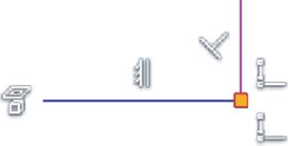
Figure 3.21 Showing constraints
At this point, the constraints present in your sketch were all inferred (placed automatically). Letting Inventor infer sketch constraints is the quickest and often most desirable way to place them; however, sometimes you'll need to constrain sketch elements manually. To do so, you can use the constraint tools found in the Constrain panel of the ribbon.
To place the Horizontal constraint back on the line from which you removed it, follow these steps:
1. On the Constrain panel of the ribbon, click the Horizontal Constraints icon (Figure 3.22).
2. Click the first line segment you sketched to set it back to horizontal. Be careful to select the line itself and not the midpoint of the line (the midpoint shows as a green dot when selected).
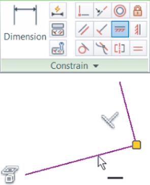
Figure 3.22 Placing a Horizontal constraint manually
Use the Line tool to add three more line segments to the sketch to complete the shape, as shown in Figure 3.23. Pay attention to the cursor glyphs as you sketch, and do not be concerned with the precise lengths of the lines or the angle of the diagonal line. You can keep this file open for use in the next set of steps or close it and use the file provided.
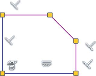
Figure 3.23 Completed sketch profile with all constraints shown
Constraint Inference and Persistence
You can suppress the automatic placement of sketch constraints (constraint inference) by holding down Ctrl on the keyboard as you sketch. You can also disable constraint inference and persistence using the Constraint Inference and Constraint Persistence buttons in the Sketch tab's Constrain panel.
If constraint persistence is disabled, you will still see the Constraint Glyph icon when sketching, and you will be able to place sketch entities in accordance with the displayed glyph; however, no actual constraint will be placed on the sketched object. For instance, sketching a line that is oriented perpendicular to an existing line without actually having a Perpendicular constraint placed automatically is possible by toggling off the constraint persistence. Coincident constraints at the endpoints of the lines will still be placed.
Constraint persistence is automatically disabled if constraint inference is turned off, but inference can be on with persistence turned off. You can also control which constraints are inferred by right-clicking in a sketch and choosing Constraint Options.
Using Degrees of Freedom to View Underconstrained Sketch Elements
Typically, your goal is to create fully constrained sketches so that no aspect of the sketch can be changed without deliberate action. To examine your sketch for underconstrained elements, you can use the Degrees of Freedom (DOF) tool. To explore DOF, you can use the file you have been working with in the previous steps or open the file mi_3a_002.ipt from the Chapter 3 directory of your Mastering Inventor 2015 folder. Make sure Sketch1 is active for edits by right-clicking it and choosing Edit Sketch. Then follow these steps:
1. To view the DOF arrows for your sketch entities, right-click anywhere in the graphics area that is not on a sketch object and choose Show All Degrees Of Freedom. Your sketch should resemble Figure 3.24.
2. Notice the arrow indicators showing the DOF for each sketched line.
3. Drag a line endpoint, and you will see that the sketch lines will drag only in a direction or orientation that follows the DOF arrows. If your sketch becomes distorted in an undesirable way, use the Undo button at the top of the screen or press Ctrl+Z to set it back as it was.
Dragging to Refine Your Sketch
Experienced Inventor users rely on the click-and-drag technique to fine-tune the general shape of a sketch rather than trying to get things precisely right from the beginning. Become familiar with this technique so you can use it to your advantage.
4. To toggle the DOF visibility back off, right-click again and choose Hide All Degrees Of Freedom.
5. Note that you can right-click an individual sketch object or a selection set of sketch objects and choose Display Degrees Of Freedom to show the DOF for just those selected objects.
6. Right-click and choose Show All Degrees Of Freedom again to have these displayed for reference in the next steps.
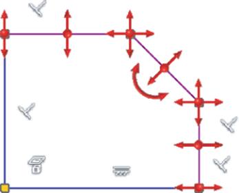
Figure 3.24 Showing the degrees of freedom in a sketch
Using Dimensions to Fully Constrain a Sketch
To work toward your goal of a fully constrained sketch, you will now add dimensions to lock down lengths, angles, and so on. Adding dimensions will remove degrees of freedom from your sketch objects and help you define the intent of your design. You will use the General Dimension tool to place dimensions on your sketch. Note that although the tool is called General Dimension, the button simply reads Dimension.
You can continue with the file you are working or open the file mi_3a_002.ipt from the Chapter 3 directory of the Mastering Inventor 2015 folder. If you're opening the prepared file, ensure that Sketch1 is active for edits by right-clicking it and choosing Edit Sketch; then right-click and choose Show All Degrees Of Freedom. Then follow these steps:
1. On the Sketch tab of the ribbon, click the Dimension button in the Constrain panel.
2. In the graphics area, click the bottom horizontal line and drag down to display the dimension.
3. Click below the line to place the dimension; you should see an Edit Dimension box, as shown in Figure 3.25. If you do not see the Edit Dimension box, you can right-click anywhere in the blank space of the graphics area and click Edit Dimension to ensure that this box shows up after each dimension is placed. Then simply click the dimension to open this input box.
4. In the Edit Dimension dialog box, type Length = 45. Because you are working in a millimeter-based part file, the units are assumed to be 45 mm, and Inventor will add the mm automatically.
Notice that the Edit Dimension box caption reads something such as d0. This indicates that this dimension parameter is named d0. Initially, Inventor names the first dimension used in the file d0, the next is named d1, and so on. By entering Length = 45, you are renaming the dimension from d0 to Length and changing this length value from the sketched value to a precise value of 45 mm. You are not required to rename your dimensions, but it is good practice to name any that you intend to reference later.
5. Click the green check mark in the Edit Dimension box, or press the Enter key to set the dimension value. Take note that the dimension “drives” the sketch line to be 45 mm long. Also notice that some of the DOF arrows have been removed.
6. Click the 45 mm dimension to edit it. Notice that the Edit Dimension box caption now reads Length and the value now reads 45 mm.
7. Change the value to 50 mm and click the green check mark.
8. Click the bottom horizontal line again and drag up, but do not click to place the dimension. You will see the same horizontal dimension displayed.
9. Click the top horizontal line and drag down; you will see the dimension change from the horizontal dimension evaluating the length of the bottom line to a vertical dimension evaluating the distance between the top and bottom lines.
10.Click in the graphics area to place the dimension.
11.Enter Width =.
12.Click the 50 mm dimension you placed in the previous steps. Notice that clicking one dimension while editing another will create a reference between the two.
13.Complete the formula to read Width = Length/2, as shown in Figure 3.26.
14.Click the green check mark or press the Enter key to set the dimension value. Observe that the Width dimension is evaluated at half the Length dimension and that it displays an fx: before the value to denote that there is a function used to evaluate this dimension. Also notice that more DOF arrows have been removed as you have further defined the sketch.
15.If your sketch has become a bit skewed, exit the Dimension tool by right-clicking and choosing Cancel (or by pressing the Esc key).
16.Click the top endpoint of the vertical line to the right and drag it so that the general shape of the profile is restored.
17.On the Sketch tab of the ribbon, click the Dimension icon in the Constrain panel, or just press D on the keyboard to start the Dimension tool again.
18.Click the vertical line to the right and then click the diagonal line. Take care to click the lines and not the endpoints of the lines because clicking the endpoints will result in a different dimension type.
19.Click in the graphics area to place the dimension. You will be presented with an edit box for an angle dimension. Enter Angle1 = 108 and click the green check mark.
20.Last, on the Sketch tab of the ribbon, click the Equal button in the Constrain panel to place an Equal constraint. Select the top horizontal line and the vertical line on the right to set those two lines equal, as shown in Figure 3.27.
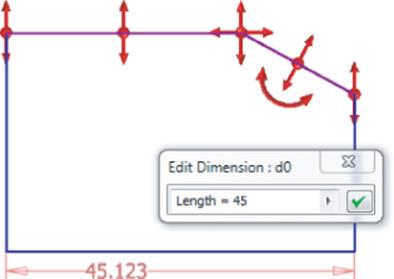
Figure 3.25 Placing a dimension on the sketch
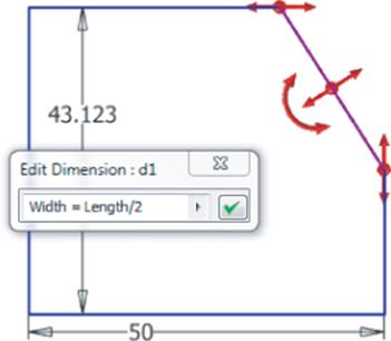
Figure 3.26 Referencing one parameter to another
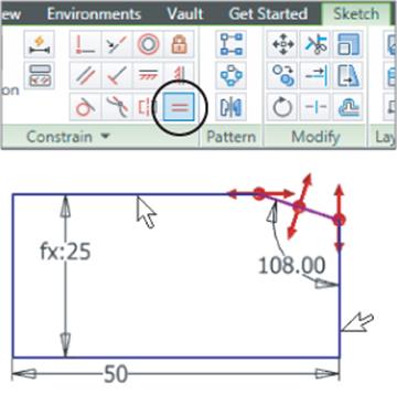
Figure 3.27 Applying an equal constraint
Your sketch is now fully constrained and should resemble Figure 3.28.
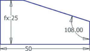
Figure 3.28 A fully constrained sketch
A fully constrained sketch is evident by taking note of the following:
· All the DOF arrows are now gone.
· You will see Fully Constrained in the status bar at the bottom right of the screen.
· Your sketch lines will have turned a different color than they were originally, before the sketch became constrained.
· A “thumb tack” appears (upper left) on the Browser Sketch icon once the sketch is fully constrained.
Understanding the Save Options
At this point, you may have seen a save reminder balloon in the top-right corner of the screen. It is always good practice to save often when working in any application. To save a part file, you must first exit the sketch and then save:
1. On the ribbon's Sketch tab, click Finish Sketch in the Exit panel. Or right-click in the graphics area and choose Finish 2D Sketch from the menu.
2. Click the Inventor button and then select Save.
3. Select your Chapter 3 folder and name the file mi_001.
You should be aware of all the save options you have and how they differ. They can all be accessed by clicking the Inventor button and choosing Save or Save As from the Application menu. Here's a list:
1. Save Choosing this option saves the active document contents to the file specified in the window title, and the file remains open.
2. Save All Choosing this option saves all open document contents to the file specified in the window title, and the files remain open.
3. Save As Choosing this option saves the active document contents to the file specified in the Save As dialog box. The original document is closed, and the newly saved file is opened. The contents of the original file are unchanged.
4. Save Copy As Choosing this option saves a copy of the active file as specified in the Save Copy As dialog box, and the original file remains open.
5. Save Copy As Template Choosing this option saves a copy of the active file as a template to the template folder, and the original file remains open.
Adjusting the Save Options
Inventor does not have an automatic save function but instead has a save reminder utility that allows you to save by just clicking within the bubble to launch a standard save operation. To adjust the save timer settings, select the Application Options button and then select the Save tab.
Making a Sketch Active for Edits
To save a file, you are required to exit the sketch. To continue making edits to the sketch once it's saved, you need to set the sketch active for edits. Here's how to activate the sketch:
1. Locate Sketch1 in the Model browser to the left of your screen and either right-click and choose Edit Sketch or double-click the Browser Sketch icon.
2. Notice that the Sketch node listed in the browser consists of the Sketch icon and the sketch name. Clicking the sketch name once and then again (don't double-click) allows you to rename the sketch. Therefore, you may want to develop a habit of double-clicking the Sketch icon rather than the sketch name to make a sketch active for edits.
Look at the browser and notice that the rest of the browser nodes are grayed out and Sketch1 is highlighted, letting you know that the sketch is active for editing. You'll also notice that the sketch tools are available.
Using Construction Geometry
Now that the sketch is active, you will add more geometry and dimensions to further explore the sketch tools. You'll start by sketching a line and then converting that line to a construction line. Construction geometry is often used to help locate and constrain normal sketch geometry.
The primary difference between construction geometry and standard geometry is that construction geometry is filtered out of profile calculations. In other words, if you have a part profile consisting of a rectangle and you run a construction line down the middle of it, resulting in two halves of the original profile, Inventor will ignore the construction line and see only one profile when you create a solid part from the sketch. To create a construction line in your sketch, follow these steps:
1. Click the Line tool in the Sketch tab's Create panel. (Recall that you can access the Line tool by pressing the L key on the keyboard as well.)
2. Start the line at the bottom-left corner of the profile, keeping an eye on your mouse pointer to ensure that you see the green dot (indicating the endpoint) and the constraint glyph (indicating that a Coincident constraint is being inferred).
3. Set the second point of the line on the midpoint of the diagonal line. Again, you should see a green dot and a coincident glyph, as shown in Figure 3.29.
4. Right-click and choose Cancel to exit the Line tool.
5. Select the new diagonal line you just created.
6. On the Sketch tab (to the far right), click the Construction icon in the Format panel to set the diagonal line as a construction line, as shown in Figure 3.30.
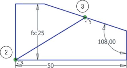
Figure 3.29 Placing a construction line showing steps 2 and 3
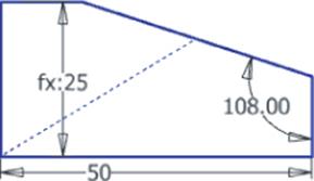
Figure 3.30 Converting to a construction line
Notice that the line has changed from a solid line to a dashed line, indicating that it is now a construction line. If you were to turn this sketch into a 3D solid at this point, Inventor would not recognize the construction line as a boundary and would therefore see only one profile from which to create the solid. However, if you had not made the diagonal line a construction line, Inventor would see two profiles, one on each side of this diagonal line.
Using the Polygon Tool and Creating an Aligned Dimension
Next, you will need to add a polygon to the midpoint of the construction line and manually place a constraint to position it in place. You will then need to place a dimension to size it:
1. In the Sketch tab's Create panel, click the Polygon tool (found under the Rectangle flyout menu).
2. Select the midpoint of the diagonal construction line, keeping an eye on your mouse pointer for the green midpoint dot and the coincident glyph.
3. Leave the polygon settings at the defaults and drag out the size and orientation to roughly match Figure 3.31.
4. In the Sketch tab's Constrain panel, click the Parallel Constraint icon.
5. Choose any of the flats on the polygon and the diagonal profile line, as shown in Figure 3.32, to make the two lines parallel.
6. In the Sketch tab's Constrain panel, click the Dimension tool.
7. On the polygon, click two opposing points to create a dimension between the two points.
8. Pull your mouse pointer to the side to preview the dimension. Notice that the orientation wants to be horizontal or vertical depending on the location of your mouse pointer.
9. Right-click and choose Aligned to force the aligned solution for this particular dimension, as shown in Figure 3.33.
10.Click the graphics window to place the dimension.
11.Enter Hex_Size = 0.375 in.
12.Click the green check mark or press the Enter key to set the dimension value. Notice that although you entered an Imperial unit of inches, Inventor converted the value automatically to the file default of millimeters. This is a powerful function that allows you to use dimension inputs to do conversion calculations on the fly.
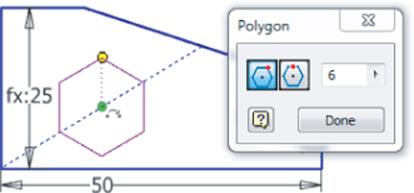
Figure 3.31 Creating a polygon
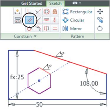
Figure 3.32 Setting the two edges to be parallel
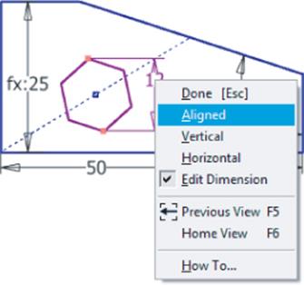
Figure 3.33 Creating a point-to-point aligned dimension
Using an Underscore in Parameter Names
When specifying parameter names, keep in mind that spaces are not allowed but you can use underscores.
Creating Mixed-Unit Formulas
You can mix any acceptable units in the same parameter formula and allow Inventor to do the conversion. For instance, entering the following into a dimension is perfectly acceptable:
3.25 ft – 1 m + 3 cm + 0.125 in
This would return a value of 23.775 mm in a millimeter part.
Using Offset and Creating a Three-Point Rectangle
You will now use the Offset and Three Point Rectangle tools to create more sketch geometry:
1. In the Sketch tab's Modify panel, click the Offset tool.
2. Before selecting any geometry, right-click anywhere that is not on the sketch geometry.
3. Ensure that the Loop Select and Constrain Offset options are both selected.
· Selecting Loop Select means that all joined geometry will be selected as a loop. With this option toggled off, individual line or curve segments are selected.
· Selecting Constrain Offset means the new geometry is constrained to be equidistant to the original. If you turn this option off, the new geometry is created unconstrained to the original.
4. Click the polygon and drag to the outside.
5. Click in the graphics window to set the offset distance.
6. Right-click and choose Cancel to exit the Offset tool.
7. In the Sketch tab's Constrain panel, click the Dimension tool (or press D on the keyboard).
8. To dimension the offset, select an edge of the original polygon and then select the corresponding edge on the new offset polygon.
9. Drag the dimension out from the center of the polygon and place it anywhere.
10.Enter Hex_Offset = 1/16 in and click the green check mark. The result should appear similar to Figure 3.34.
11.In the Sketch tab's Create panel, click the Rectangle flyout and choose Rectangle Three Point (Figure 3.35).
12.Create the rectangle using the three points shown in Figure 3.36. Click the top-left point first, then the top-right point, and then the bottom-middle point. Make certain you are seeing the green snap dots and Coincident constraint glyphs at each point.
13.Right-click and choose Cancel. If your rectangle is not fully constrained, click the corner and drag it away from the line and then back to the line, setting it on the line when you see the constraint glyph.
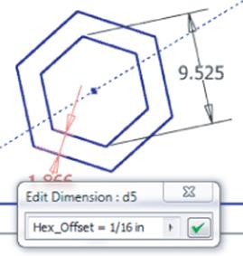
Figure 3.34 The offset polygon
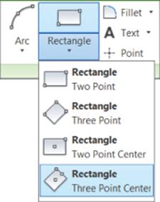
Figure 3.35 Accessing the Rectangle Three Point tool
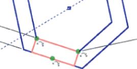
Figure 3.36 Placing a three-point rectangle
This completes the creation of most of your sketch objects in this exercise. Save your file and use it in the next set of steps. Your sketch should resemble Figure 3.37.
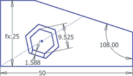
Figure 3.37 Your completed sketch
To Trim or Not to Trim
You can find the Trim tool in the Sketch tab's Modify panel. Although you might be tempted to use the Trim tool to tidy up the sketch, keep in mind that in Inventor you are creating solid models from these sketches, and therefore trimming “extra” lines from a sketch is not required.
More important, though, trimming these extra lines in a sketch often does more harm than good. This is because all the lines in the sketch have constraint relationships between them. When you use the Trim tool, you are inadvertently removing constraints that were holding your sketch objects together. As a rule, use the Trim tool only when necessary.
You might find the Split tool is actually what you want. Split will divide a line into separate segments without removing them. And it will also maintain sketch constraints. You can find the Split tool in the Sketch tab's Modify panel as well. Hover your mouse pointer over it for a moment, and you will get a dynamic tool tip showing you how it works.
Creating Driven Dimensions
Now you'll take a look at creating driven dimensions and editing the parameters you just created through the Parameters dialog box. Because dimensions define the parameters of your design, you can use them to control the design intent. At other times you may want to place a dimension that does not drive the design but instead is driven by other parameters. In those cases, such dimensions are called driven dimensions.
Unlike Inventor's standard parametric dimensions, driven dimensions do not change the geometry but instead change when the geometry changes. Driven dimensions are created either by placing a dimension on already defined geometry or by explicitly making them driven.
You can use your current file or open the file mi_3a_003.ipt from the Chapter 3 directory of your Mastering Inventor 2015 folder. If you're opening the prepared file, ensure that Sketch1 is active for edits by right-clicking it and choosing Edit Sketch. Follow these steps to explore driven dimensions:
1. Double-click the 50 mm Length dimension.
2. Replace the value of 50 with 60 and press the Enter key.
3. Take note that the vertical dimension retains the intent of your design and remains at half the Length value.
4. In the Sketch tab's Constrain panel, click the Dimension tool (or press D on the keyboard).
5. Select the vertical line on the right of the sketch and click the graphics window to place the dimension.
6. Depending on the options you have selected in the Sketch tab of the Application Options dialog box, you might be presented with a dialog box warning you that this dimension will overconstrain the sketch. If so, click Accept. In either case you'll place the dimension as a driven dimension by clicking the screen.
Notice that the dimension is created in parentheses, denoting it is driven by other parameters and, therefore, is considered a reference parameter. Driven dimensions are useful in capturing dimensions for use in the calculations of other features.
7. Switch from the Sketch tab to the Manage tab on the ribbon.
8. Click the Parameters tool. This will open the Parameters dialog box listing all the dimensions you've created in this part as parameters, as shown in Figure 3.38.
9. Enter Vertical_Leg for the reference parameter name. Be sure to use an underscore rather than a space.
10.Still in the Parameters dialog box, change the Length value from 60 mm to 65 mm.
If you have the Immediate Update check box selected, the dimension is automatically updated in the sketch. If not, you will need to update the dimension manually by clicking the Update button on the Quick Access bar at the top left of the screen, as shown inFigure 3.39.
11.Ensure that the Immediate Update check box is selected; then click Done to return to the sketch.
12.Right-click in the graphics area and choose Dimension Display ![]() Expression from the context menu. Observe the dimension names and expression values, as shown in Figure 3.40.
Expression from the context menu. Observe the dimension names and expression values, as shown in Figure 3.40.
13.Right-click in the graphics area and choose Dimension Display ![]() Value from the context menu to set the dimension display back to display the calculated value.
Value from the context menu to set the dimension display back to display the calculated value.
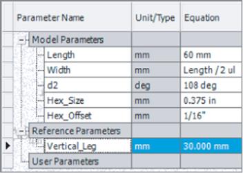
Figure 3.38 Parameters dialog box
Figure 3.39 Update button on the Quick Access bar
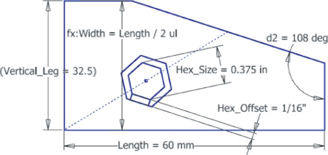
Figure 3.40 Displaying dimension expressions
You can leave this file open and use it in the next set of steps.
Dimension Arrangement
Although the arrangement of sketch dimensions is not all that important because these dimensions will ultimately be consumed by a solid model, it is still helpful to be able to read them in the sketch. You can rearrange jumbled sketch dimensions by clicking the text/numbers and dragging them as you like. Note too that this must be done once you've exited the Dimension tool because clicking a dimension with the Dimension tool active edits that dimension. You'll notice that because of the intelligence you've built into the sketch, when you modify and update the Length dimension (parameter) value, the dependent values change as well.
Next, you'll change a driving dimension to a driven dimension and a driven to a driving. By doing this, you can modify the intent of your design and change which parameter is a key input. You can use your current file or open the file mi_3a_004.ipt from the Chapter 3directory of your Mastering Inventor 2015 folder. If you're opening the prepared file, ensure that Sketch1 is active for edits by right-clicking it and choosing Edit Sketch. Then follow these steps:
1. Click the 65 mm Length dimension.
2. In the Sketch tab's Format panel, click the Driven Dimension tool. Notice that the Length dimension is now set in parentheses, indicating that it is now driven rather than driving.
3. Double-click any blank area in the graphics window to deselect the previous dimension.
4. Select the vertical dimension that is in parentheses.
5. Click the Driven Dimension tool again to toggle this dimension from a driven to a driving dimension.
6. Double-click the vertical dimension to edit its value.
7. Enter 40 mm and click the green check mark. Notice that the Vertical_Leg parameter now drives the Length parameter, which still drives the Width dimension.
You are beginning to see the power of parametric design. Next, you'll add a user parameter and use it to drive the design. A user parameter is a design input that is not based on the geometry in the sketch. This allows you to enter user variables to drive your design.
8. From the Manage tab on the ribbon, select the Parameters tool. This will open the Parameters dialog box.
9. Click the Add Numeric button found at the bottom of the dialog box to create a new user parameter.
10.Enter Wrench_Size for the user parameter name.
11.Click the mm in the Unit/Type column and select the inch input from the Length category.
12.Enter 0.4 for the Equation column input.
13.Edit the equation input for the Hex_Size parameter and replace 0.375 in with Wrench_Size.
You have now set the Hex_Size parameter to be driven by your user parameter named Wrench_Size. Your inputs should look like Figure 3.41.
14.Click the Done button to close the Parameter dialog box and then use the Update button to update the sketch if needed.
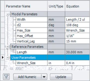
Figure 3.41 Creating a user parameter
Now that you've been introduced to the basics of creating a parametric sketch, you'll take a more in-depth look at these tools in the next sections. You can close this file without saving changes.
Taking a Closer Look at Sketch Constraints
In the following sections, you'll take a closer look at each of the available sketch constraints. As you proceed, it may occur to you that you could use other sketch constraints in place of the one suggested in the exercise steps. Be aware that as you create sketch constraints, there are often multiple solutions to get the same result.
In the following exercises, you will be opening a series of part files, setting the sketch as active for edits, and applying different sketch constraints. Each of these files demonstrates the function of a different type of sketch constraint. All of these files contain a sketch called <—Double Click to Edit (Sketch 1). You will edit the sketch in each file and apply the appropriate sketch from the Constrain panel of the Sketch tab, shown in Figure 3.42.
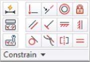
Figure 3.42 Constraint tools
The Tangent Constraint
The Tangent constraint places one object or edge in a tangency to another object or edge. Objects can be tangent to each other even if they do not share a physical point. Follow these steps to explore the Tangent constraint:
1. From the Get Started tab, click the Open button (or press Ctrl+O on the keyboard).
2. Browse for the file mi_3h_001.ipt in the Chapter 3 directory of your Mastering Inventor 2015 folder, and click Open.
3. In the Model browser, double-click Sketch1 to edit it. Or right-click it and choose Edit Sketch.
4. Press the F8 key to show all the constraints. Note that there is no Tangent constraint between the large circle and the lines.
5. In the Sketch tab's Constrain panel, click the Tangent button. Click the line and circle, as shown in Figure 3.43.
6. Repeat to set a Tangent constraint on the top line and the same circle.
7. Right-click and choose Cancel.
8. Press the F8 key to show all the constraints and note the new Tangent constraints.
9. You can exit the file without saving once you have finished.
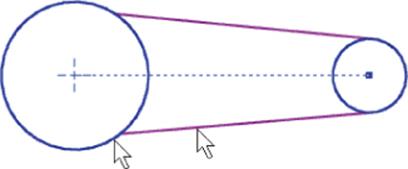
Figure 3.43 Placing a Tangent constraint
The Perpendicular Constraint
The Perpendicular constraint constrains objects or edges to be always perpendicular. Follow these steps to explore the Perpendicular constraint:
1. From the Get Started tab, click the Open button.
2. Browse for the file mi_3h_002.ipt in the Chapter 3 directory of your Mastering Inventor 2015 folder and click Open.
3. In the Model browser, double-click Sketch1 to edit it. Or right-click it and choose Edit Sketch.
4. In the Sketch tab's Constrain panel, click the Perpendicular button.
5. Click the vertical line, as shown in Figure 3.44, and then select either of the horizontal lines.
6. Right-click and choose Cancel.
7. Press the F8 key to show all the constraints, noting the new Perpendicular constraint.
8. You can exit the file without saving once you have finished.
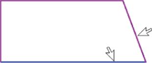
Figure 3.44 Placing a Perpendicular constraint
The Parallel Constraint
The Parallel constraint constrains objects or edges to be always parallel. Follow these steps to explore the Parallel constraint:
1. From the Get Started tab, click the Open button.
2. Browse for the file mi_3h_003.ipt located in the Chapter 3 directory of the Mastering Inventor 2015 folder and click Open.
3. In the Model browser, double-click Sketch1 to edit it. Or right-click it and choose Edit Sketch.
4. In the Sketch tab's Constrain panel, click the Parallel button.
5. Click the lines as shown in Figure 3.45.
6. Right-click and choose Cancel.
7. Press the F8 key to show all the constraints, and note the new Parallel constraint.
8. You can exit the file without saving once you have finished.
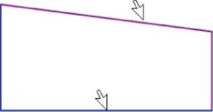
Figure 3.45 Placing a Parallel constraint
The Coincident Constraint
The Coincident constraint places objects or points in contact with another object. Follow these steps to explore the Coincident constraint:
1. From the Get Started tab, click the Open button.
2. Browse for the file named mi_3h_004.ipt in the Chapter 3 directory of the Mastering Inventor 2015 folder and click Open.
3. In the Model browser, double-click Sketch1 to edit it. Or right-click it and choose Edit Sketch.
4. In the Sketch tab's Constrain panel, click the Coincident button.
5. Click the center of the circle and then on the center point, as shown in Figure 3.46.
6. Right-click and choose Cancel.
7. Click the endpoint of the vertical line at the top-right corner of the rectangular shape and hold down as you drag to close the profile. Note that a Coincident constraint is placed.
8. Press the F8 key to show all the constraints, and note the new Coincident constraints, as shown by the yellow dots.
9. Hover your mouse pointer over the dots to see Coincident constraint symbols.
10.You can exit the file without saving once you have finished.
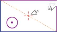
Figure 3.46 Placing a Coincident constraint
The Concentric Constraint
The Concentric constraint places arcs and circles so that they share the same center point. Follow these steps to explore the Concentric constraint:
1. From the Get Started tab, click the Open button.
2. Browse for the file mi_3h_005.ipt located in the Chapter 3 directory of your Mastering Inventor 2015 folder and click Open.
3. In the Model browser, double-click Sketch1 to edit it. Or right-click it and choose Edit Sketch.
4. In the Sketch tab's Constrain panel, click the Concentric button.
5. Click the edge of the circle and then the arc, as shown in Figure 3.47.
6. Right-click and choose Cancel.
7. Press the F8 key to show all the constraints, and note the new Concentric constraint.
8. You can exit the file without saving once you have finished.
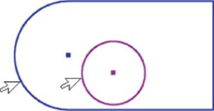
Figure 3.47 Placing a Concentric constraint
The Collinear Constraint
The Collinear constraint lines up a line object or ellipse axis on the same line as another line object or ellipse axis. Follow these steps to explore the Collinear constraint:
1. From the Get Started tab, click the Open button.
2. Browse for the file mi_3h_006.ipt located in the Chapter 3 directory of your Mastering Inventor 2015 folder and click Open.
3. In the Model browser, double-click Sketch1 to edit it. Or right-click it and choose Edit Sketch.
4. In the Sketch tab's Constrain panel, click the Collinear icon.
5. Click the lines as shown in Figure 3.48.
6. Right-click and choose Cancel.
7. Press the F8 key to show all the constraints, and note the new Collinear constraint.
8. You can exit the file without saving once you have finished.
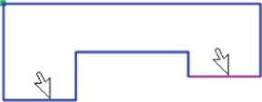
Figure 3.48 Placing a Collinear constraint
The Horizontal Constraint
The Horizontal constraint makes an object line up parallel to the x-axis. Two points may also line up horizontally. Follow these steps to explore the Horizontal constraint:
1.
From the Get Started tab, click the Open button.
2. Browse for the file mi_3h_007.ipt located in the Chapter 3 directory of your Mastering Inventor 2015 folder and click Open.
3. In the Model browser, double-click Sketch1 to edit it. Or right-click it and choose Edit Sketch.
4. In the Sketch tab's Constrain panel, click the Horizontal button.
5. Click the line as shown in Figure 3.49, noting the new horizontal alignment.
6. Click both of the points, as indicated in Figure 3.49, noting that they will line up horizontally.
7. Right-click and choose Cancel.
8. Press the F8 key to show all the constraints, and note the new Horizontal constraints.
9. You can exit the file without saving once you have finished.
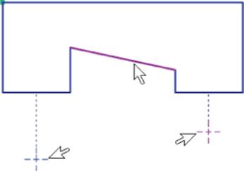
Figure 3.49 Placing Horizontal constraints
Horizontal and Vertical Orientation
Because the terms Horizontal and Vertical are dependent on your current view orientation, placing Horizontal and Vertical constraints can sometimes be confusing. To help with this, Inventor will display a light dotted line when placing a Horizontal or Vertical constraint. This line shows the orientation that Inventor is considering correct at the time of placement.
Keep in mind that no matter how you change your view orientation Inventor maintains the definition of horizontal and vertical based on the coordinate system of the file.
The Vertical Constraint
The Vertical constraint makes an object line up parallel to the y-axis. Two points may also line up vertically. Follow these steps to explore the Vertical constraint:
1. From the Get Started tab, click the Open button.
2. Browse for the file mi_3h_008.ipt located in the Chapter 3 directory of your Mastering Inventor 2015 folder and click Open.
3. In the Model browser, double-click Sketch1 to edit it. Or right-click it and choose Edit Sketch.
4. In the Sketch tab's Constrain panel, click the Vertical button.
5. Click the line as shown in Figure 3.50, noting the new vertical alignment.
6. Click both of the points as indicated in Figure 3.50, noting that they will line up vertically.
7. Right-click and choose Cancel.
8. Press the F8 key to show all the constraints, and note the new Vertical constraints.
9. You can exit the file without saving once you have finished.
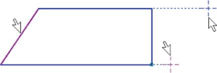
Figure 3.50 Placing Vertical constraints
The Equal Constraint
The Equal constraint makes two objects equal in length or radius. Follow these steps to explore the Equal constraint:
1. From the Get Started tab, click the Open button.
2. Browse for the file mi_3h_009.ipt located in the Chapter 3 directory of your Mastering Inventor 2015 folder and click Open.
3. In the Model browser, double-click Sketch1 to edit it. Or right-click it and choose Edit Sketch.
4. In the Sketch tab's Constrain panel, click the Equal button.
5. Click the two circles as shown in Figure 3.51, and notice that they become equal.
6. Click the lines, as indicated in Figure 3.51, noting that they too will become equal. You can make two of the vertical lines equal as well if you like.
7. Right-click and choose Cancel.
8. Press the F8 key to show all the constraints, and note the new Equal constraints.
9. You can exit the file without saving once you have finished.
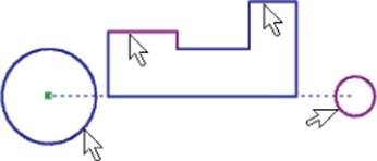
Figure 3.51 Placing Equal constraints
The Fix Constraint
The Fix constraint anchors any geometry or point in place within the part sketch. You should use this constraint sparingly. Follow these steps to explore the Fix constraint:
1. From the Get Started tab, click the Open button.
2. Browse for the file mi_3h_010.ipt located in the Chapter 3 directory of your Mastering Inventor 2015 folder and click Open.
3. In the Model browser, double-click Sketch1 to edit it. Or right-click it and choose Edit Sketch.
4. Drag the corner as indicated in Figure 3.52, and notice that it may be repositioned freely.
5. In the Sketch tab's Constrain panel, click the Fix button.
6. Click the same corner as before.
7. Right-click and choose Cancel.
8. Drag the corner again, and notice that it is now fixed to that position.
9. Apply another fixed constraint to the vertical line next to the rectangle, and be sure to click the line rather than the endpoint.
10.Right-click and choose Cancel to exit the constraint tool; then drag either endpoint of the line. While the line position is fixed, the endpoints are still free to change.
11.Press the F8 key to show all the constraints, and note the new Fix constraints.
12.You can exit the file without saving once you have finished.
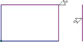
Figure 3.52 Placing Fix constraints
The Symmetric Constraint
The Symmetric constraint creates a “mirror” constraint between two similar objects. This constraint relies on a line to serve as a centerline about which objects are to be symmetrical. You need to specify the centerline only once during the command cycle. Follow these steps to explore the Symmetric constraint:
1. From the Get Started tab, click the Open button.
2. Browse for the file mi_3h_011.ipt located in the Chapter 3 directory of your Mastering Inventor 2015 folder and click Open.
3. In the Model browser, double-click Sketch1 to edit it. Or right-click it and choose Edit Sketch. You'll work with the sketch shown in Figure 3.53.
4. In the Sketch tab's Constrain panel, click the Symmetric button.
5. Click the circle on the left and then click the circle on the right.
6. Click the centerline and observe that the circles become symmetric.
7. Continue by clicking a line on the square on the left side of the sketch.
8. Click the corresponding line on the rectangle on the right. Notice that this time you did not need to select the centerline. When using the Symmetric constraint, you need to establish the centerline only once.
9. Continue making the sketch symmetric by selecting lines on the left of the sketch and then selecting the corresponding lines on the right side.
10.Right-click and choose Cancel when the sketch is symmetric.
11.Press the F8 key to show all the constraints; note the new Symmetric constraints.
12.You can exit the file without saving once you have finished.
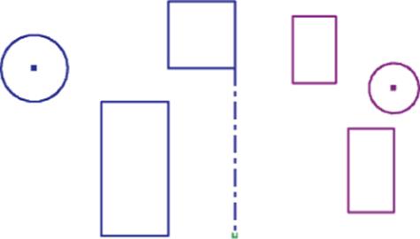
Figure 3.53 Placing Symmetric constraints
The Smooth Constraint
The Smooth constraint creates a continuous curvature (G2) condition between a spline and another sketch object, such as a line, arc, or spline. The G2 condition brings the curve out past the tangency point to create a smooth transition from one curve into the next. Follow these steps to explore the Smooth constraint:
1. From the Get Started tab, click the Open button.
2. Browse for the file mi_3h_012.ipt in the Chapter 3 directory of your Mastering Inventor 2015 folder and click Open.
3. In the Model browser, double-click Sketch1 to edit it. Or right-click it and choose Edit Sketch.
4. In the Sketch tab's Constrain panel, click the Smooth button.
5. Click the spline and arc as indicated in Figure 3.54.
6. Right-click and choose Cancel.
7. Press the F8 key to show all the constraints; note the new Smooth constraint.
8. You can exit the file without saving once you have finished.
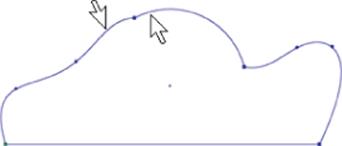
Figure 3.54 Placing a Smooth constraint
Gaining More Sketch Skills
Many tools are available in the sketch environment, each used to draw different types of geometry or modify geometry in a different way. Many of these are covered in the following pages, but as a reminder, if you hover your mouse pointer over the tool and then pause, you will see a tool tip appear; hover a bit longer, and a larger, more informative tool tip will appear. These progressive tool tips are a great help when you're attempting to use tools that you don't often use and you need a helpful hint to remember what they do and how they do it.
Creating Arcs
You can create sketch arcs by using one of three arc tools available in Inventor's sketch environment. All three arc types are available in a drop-down menu in the Sketch tab's Create panel. Once placed, the three arcs behave the same; it is simply the manner in which they are created that differentiates them.
A three-point arc is an arc defined by two endpoints and a point on the arc. The first click sets the first endpoint, the second sets the other endpoint, and the third point sets the direction and radius of the arc, as shown in Figure 3.55.
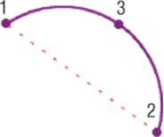
Figure 3.55 A three-point arc
A center-point arc is an arc defined by a center point and two endpoints. The first click sets the center point, the second sets the radius and start point, and the third sets the endpoint and/or arc length, as shown in Figure 3.56.
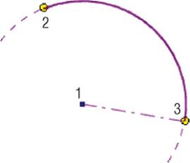
Figure 3.56 A center-point arc
A tangent arc is an arc from the endpoint of an existing curve. The first click must be on the endpoint of an existing curve and sets a Tangent constraint on the endpoint. The second point sets the end of the tangent arc, as shown in Figure 3.57.
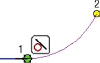
Figure 3.57 A tangent arc
Additionally, you can create arc segments while using the Line tool, as illustrated in Figure 3.58.
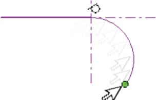
Figure 3.58 Creating an arc with the Line tool
To do so, follow these steps:
1. From the Get Started tab, click the Open button.
2. Browse for the file mi_3h_013.ipt located in the Chapter 3 directory of your Mastering Inventor 2015 folder and click Open. The goal here is to re-create the oblong shape already present in the sketch.
3. In the Model browser, double-click Sketch1 to edit it. Or right-click and choose Edit Sketch.
4. In the Sketch tab's Create panel, click the Line icon.
5. Click the projected origin point as the start point of the line and then release the mouse button. This is the small dot located below the oblong shape and at 0,0 of the sketch.
6. Pull your mouse pointer to the right, making sure you see a horizontal or parallel glyph, indicating that your line is horizontal.
7. Click the screen to set the second point of the line and then release the mouse button.
8. Now to sketch an arc without exiting the Line tool, click and hold the endpoint you just created and then (still holding down on the mouse button) drag your mouse pointer out to preview the arc. If the arc previews in the wrong direction, simply return your mouse pointer to the endpoint and try again. It may be helpful to “trace” the guideline cross and exaggerate the arc size to get the direction established and then bring your mouse pointer back in to get the size you want.
9. Release the mouse button to end the arc and continue the Line tool.
10.Continue creating line/arc segments, or right-click and choose Cancel to exit the Line tool. Practice this a few times, and you'll have it mastered in a short time.
Creating Automatic Tangents with the Line Tool
When adding tangent line segments to a circle or arc, you can apply the Tangent constraints automatically. To do so, start the Line tool and click and hold on the circle or arc on which you intend to create the tangent line. You will see a tangent glyph. You can drag the line segment out to the length and orientation desired. To change the tangent direction, simply rub your cursor over the tangent point again and drag the line segment the other direction. Figure 3.59 illustrates this technique.
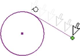
Figure 3.59 Creating an arc with the Line tool
Understanding the Point/Center Point Tool
You can use the Point/Center Point tool, found in the Sketch tab's Create panel, to create center marks for locating hole centers and specific coordinate points. Center points are used by the Hole and Sheet Metal Punch tools in the modeling environment to automatically locate hole centers. Points, or sketch points as they are often called, are initially ignored by the Hole and Punch tools but can be manually selected for use. Another key difference between the two point types is that sketch points are deleted when the associated geometry is deleted. Center points are not.
You can change the center point to a sketch point, or vice versa, by selecting the point and clicking the Center Point button on the Format menu of the Sketch tab, as shown in Figure 3.60.

Figure 3.60 Using the Center Point button to switch points from simple sketch points (right) to center points (left)
Creating Sketched Slots
In Inventor 2015 you can use the new slot sketch tools on the Sketch tab to create the following types of slots:
· Center to Center Linear Slots
· Overall Length Linear Slots
· Three Point Arc Slots
· Center Point Arc Slots
To see how each slot type is created, you can pause your cursor over the tool and wait for the extended flyout panel to show you the “picks and clicks.”
Projecting Geometry
When creating a sketch on the face of existing geometry or a work plane, you can project existing points and edges into the sketch by using the Project Geometry tool in the Sketch tab's Create panel. To take a quick look at this functionality, follow these steps:
1. From the Get Started tab, click the Open button.
2. Browse for the file mi_3h_014.ipt in the Chapter 3 directory of your Mastering Inventor 2015 folder and click Open.
3. In the Model browser, double-click Sketch3 to edit it. Or right-click and choose Edit Sketch.
4. In the Sketch tab's Create panel, click the Project Geometry icon.
5. Click the edges of the red oval-shaped profile.
6. When you have the complete profile projected into the sketch as shown in Figure 3.61, click the Finish Sketch button.
7. Next, in the Model browser, double-click Sketch4 to edit it. Or right-click and choose Edit Sketch.
8. Once the sketch is active, right-click and choose Slice Graphics (or press F7 on the keyboard) to slice the part along the sketch plane.
9. In the Sketch tab's Create panel, click the drop-down for Project Geometry and choose Project Cut Edges.
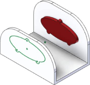
Figure 3.61 Using the Project Geometry tool to project the profile into the active sketch
You'll see that the sliced edges are now projected as sketch lines into the sketch. These lines can be used to dimension or constrain other sketch geometry too and will remain associative to the sliced features. Oftentimes a work plane is used to create a sketch in the middle of a part such as this. Work planes are covered in Chapter 4, “Basic Modeling Techniques.” For now, you can finish the sketch and close the file without saving changes.
Breaking the Link with Projected Geometry
Projected geometry is created by projecting an edge or a face. When you project faces, a browser node for a projected loop is created under the Sketch node. When you project edges, no browser node is created. You might need to break the link of the projected geometry in order to modify it.
· To break the link of projected faces, right-click the Projected Loop browser node and select Break Link.
· To break the link of projected edges, right-click the edge itself and choose Break Link.
Learning More about Dimensions
In the following sections, you'll take a look at more Dimension tools and settings to help you master this important part of sketch creation.
Using One General Dimension Tool to Do It All
It is important to understand that you get different results from the Dimension tool depending on what geometry is selected or in what order it is selected. Here are the dimension types you can place with the General Dimension tool:
1. Linear dimension from one object: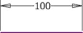
2. Linear dimension between two objects: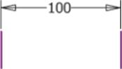
3. Aligned dimension between two objects: Select the objects and right-click to choose the Aligned solution.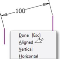
4. Angular dimension between two edges: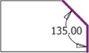
5. Angular dimension between three points: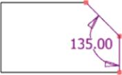
6. Dimensions to circles or arcs: Select the object and then right-click to switch between diameter or radius solutions for either arcs or circles.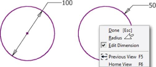
7. Dimension to the center of arcs and circles: Select the first element of the dimension and then click anywhere on the arc or circle. Note the linear glyph indicating the linear solution you will get.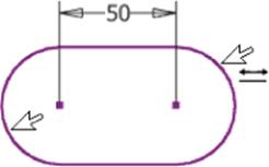
8. Dimension to the tangent of arcs and circles: Select the first element of the dimension and then click the tangent when you see the tangent glyph appear.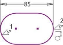
Setting Up Automatic Dimensions
In addition to the General Dimension tool, Inventor has an Automatic Dimensions And Constraints tool. It is generally poor practice to use the Automatic Dimensions And Constraints tool to apply all dimensions to your sketches because it will do so in an illogical way. However, you can benefit from this tool by placing the dimensions that define the intent of your design with the General Dimension tool and then allowing the Automatic Dimensions And Constraints tool to place the remaining dimensions to fully constrain the sketch.
To take a look at the Automatic Dimensions And Constraints tool in action, follow these steps:
1. From the Get Started tab, click the Open button.
2. Browse for the file named mi_3h_015.ipt in the Chapter 3 directory of your Mastering Inventor 2015 folder and click Open.
3. In the Model browser, locate Sketch1; double-click to edit or right-click and choose Edit Sketch.
4. In the Sketch tab's Constrain panel, click the Automatic Dimensions And Constraints icon. Notice that the Auto Dimension dialog box shows the number of dimensions required to fully constrain the sketch.
5. Accept the default settings to add both dimensions and constraints.
6. With the Curves button enabled, select all the geometry in the sketch (you can do this quickly with a selection window).
Figure 3.62 shows that two dimensions will be added to fully constrain the sketch.
7. Click Apply to add dimensions to the selected geometry.
8. When finished, click Done.
9. You can close the file without saving changes.
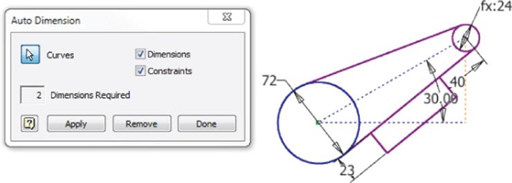
Figure 3.62 Adding automatic dimensions
Note that you can also use the Automatic Dimensions And Constraints tool to apply just sketch constraints by deselecting the Dimensions check box.
Working with Sketch Centerlines
You can create centerlines in sketches either by creating a regular line and then changing it to a centerline or by changing the line type to centerline first and then creating the line. Dimensioning to a centerline gives you a diametric solution by default, but you can opt for a linear solution by right-clicking and deselecting Linear Diameter, as shown in Figure 3.63. In the following exercises, you will find the steps for both methods of centerline creation as well as how to change the solution when dimensioning to a centerline.
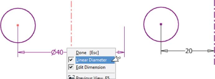
Figure 3.63 Dimensioning to a centerline
To change to centerline line type before creating sketch geometry, follow these steps:
1. Ensure that the sketch is active for editing by double-clicking it or right-clicking and choosing Edit Sketch.
2. On the Sketch tab, click the Centerline icon in the Format panel.
3. Now use the Line tool to sketch lines as you would normally. Note that the Centerline icon stays pushed in (On) until you click it again.
To change an existing line to a centerline, follow these steps:
1. Ensure that the sketch is active for editing by double-clicking it or right-clicking and choosing Edit Sketch.
2. Select the sketch lines you intend to be centerlines.
3. On the Sketch tab, click the Centerline icon in the Format panel.
To create a dimension to a centerline, follow these steps:
1. Ensure that the sketch is active for editing by double-clicking it or by right-clicking and choosing Edit Sketch.
2. On the Sketch tab, click the Dimension icon in the Constrain panel.
3. Select an object to the side of the centerline.
4. Click the centerline. Note the diametric diameter.
5. Right-click and note the Linear Diameter option.
6. Place the dimension on the screen.
Measuring Geometry
You can use the Measure tools to gather measurements from your model without the need to place a dimension in your sketch. These tools can be accessed from the Inspect tab, from the Tools tab, or by right-clicking any empty place in the graphics area of the screen and choosing Measure from the context menu. When using the Tools tab, you can click the drop-down on the Measure panel to reveal the Region Measure option. The measurement tools include the following:
1. Measure Distance Measures the length lines and arcs, the distance between points, and the radius or diameter of a circle.
2. Measure Angle Measures the angle between two lines or points.
3. Measure Loops Measures the length of closed loops.
4. Measure Area Measures the area of enclosed regions.
5. Get Region Properties Measures the area and perimeter and the Area Moment Of Inertia properties of sketch loop regions. This tool is available only while editing 2D sketches. Figure 3.64 shows the use of the Measure Region tool.
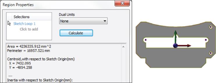
Figure 3.64 Measuring a region
Creating Sketches from AutoCAD Geometry
Converting accurate, dimensioned 2D drawings eliminates the need to redraw all of the original geometry. Inventor allows selective importing of 2D drawings with associative geometry directly into a new part sketch. If you have an existing drawing library of 2D AutoCAD files, you may find it beneficial to use those files to create new 3D feature-based parametric parts in Inventor. Success in importing existing drawings depends on the following criteria:
· The AutoCAD file must contain accurate original geometry.
· Duplicate geometry must be deleted from the AutoCAD file.
· Proper AutoCAD drawing techniques must be employed in creating the AutoCAD file. For example, there must be only one line segment between any two points. Two shorter lines appearing as a single line will be imported exactly as drawn in the AutoCAD file.
· For dimensions to be converted to Inventor parametric dimensions, the existing AutoCAD dimensions must be associative to the geometry. Disconnected dimensions (AutoCAD Defpoints not snapped to the proper geometry location) will cause problems when converted to Inventor dimensions.
Importing Existing AutoCAD Designs
You begin the process of converting an AutoCAD drawing to Inventor parts by creating a new part file. When in active sketch mode, you can import AutoCAD sketch geometry by selecting the Insert panel on the Sketch tab and clicking the Insert AutoCAD File icon. To see this process yourself, follow these steps:
1. From the Get Started tab, select the New button.
2. In the New File dialog box, click Metric in the left pane and click the Standard(mm).ipt icon.
3. Click Create to create a new part file based on this template.
4. On the Insert panel of the Sketch tab, click the Insert AutoCAD File icon.
5. In the resulting dialog box, select the file Import1.dwg from the Chapter 3 directory of your Mastering Inventor 2015 folder.
6. Click Open to start the conversion process. Once the AutoCAD file opens, you will move into a series of Import Destination Options pages. The first page is mostly grayed out except for specifying units, constraining endpoints, and optionally applying geometric constraints upon import under most conditions. Set your selections as shown in Figure 3.65.
7. Click Finish to complete the import.
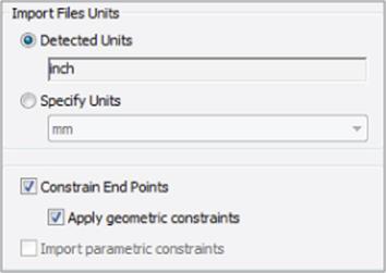
Figure 3.65 DWG import options

Creating Sketches from a Graphic Image
Occasionally you may need to create a part from a scanned image or napkin sketch. To do this, you can insert the scanned image or napkin sketch right into your sketch and sketch over the top of it. Although this is generally not a good approach for reproducing precise machined parts, it is a valid workflow when designing consumer products and the general shape and feel of parts need to be captured. If you have a need for this type of design on a regular basis, you may want to investigate Autodesk® AliasStudio™ software as well. Here are the general steps for creating sketches from an image:
1. Place an image into a part sketch by clicking the Insert Image icon on the Sketch tab.
2. Browse for the image you want to place into the sketch and click Open when the image is located.
3. The mouse pointer is then attached to the upper-left corner of the image. To place the image, simply click an insert point on-screen.
4. Once the image is placed, the edges of the image can be dimensioned and constrained like any other sketch entity.
Now you can sketch on top of the image, tracing the edges to create the profile, and then use the Dimension tool to tweak the sketch as required.
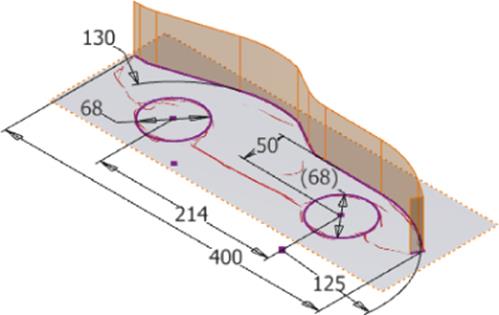
When an AutoCAD drawing is imported into a sketch, Inventor records the unit type of the AutoCAD file. By default, the unit type is displayed within the import dialog box but grayed out. If the unit type is not correct or the unit is of a different type than you require, you may input a different input-unit type.
Selecting the Constrain End Points box allows insertion of Coincident constraints between sketch objects found to have endpoints that occupy the same coordinates. When the Apply Geometric Constraints box is checked, Inventor will add minimal constraints to the imported AutoCAD geometry. Note too that although some dimensions will not be imported, those that are will be parametric Inventor dimensions. Figure 3.66 shows the result of importing the file Import1.dwg.
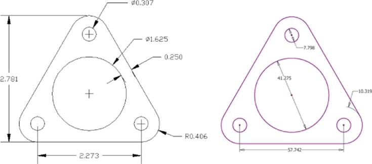
Figure 3.66 Original DWG (left) and finished imported sketch (right)
If the AutoCAD geometry was created at the 0,0 origin, then it should import into Inventor at the same location. If the AutoCAD geometry is not located at the origin of the sketch, you can use the Move command, selecting both the geometry and any dimensions, to move the entire imported sketch into the proper location. You might also prefer to redefine the geometry origin in AutoCAD and then import or reimport it into Inventor.
You should note that this imported drawing might be further broken down into separate features. For instance, each hole could be a separate feature. Note too that having the round corners modeled as features separate from the base feature allows for easier edits in Inventor.
Copying and Pasting Existing AutoCAD Designs into Inventor
Although using the import wizard as described earlier works without having AutoCAD open or even installed, you can import AutoCAD geometry in an even more efficient manner by simply copying from an open AutoCAD file straight into an Inventor sketch, as described in these steps:
1. Open the existing file in AutoCAD.
2. From an open AutoCAD file, simply select the geometry you want to import, right-click, and choose Copy, thereby copying the selected objects to the Windows clipboard.
3. In Inventor and with a 2D sketch active for editing, right-click and choose Paste. You will be presented with a bounding-box preview of the pasted entities.
4. At this point, you can right-click and choose Paste Options to ensure that the insert scale is correct or click the graphics window to place the pasted geometry.
Although importing geometry from AutoCAD can be an efficient way to reuse existing AutoCAD files, experienced Inventor users generally prefer to model parts from scratch rather than import from AutoCAD. Importing from AutoCAD almost never provides results that are in line with the design intent of the part unless you just get lucky. Although you may find this to be helpful initially, you will learn that importing AutoCAD files has a place in Inventor but should not be used as a substitute for creating robust parametric Inventor models.
Creating and Using 3D Sketches
3D sketches permit the creation of nonplanar 3D features. 3D sketches are created in single-part files only and comprise geometry located in various XYZ locations or points within the file. Although a 3D sketch may lie in a 2D plane, in most designs that will not be the case. 3D sketches should never be used for creating geometry that could be created within the 2D sketch environment. The 3D sketch tool is accessible only from within the part environment; however, you can project geometry from an assembly into the part to create the 3D sketch.
Creating a 3D Path
3D sketches are often used to define paths for modeling features such as sweeps and lofts and are generally created based on existing geometry. You can use a 3D sketch to create objects such as tubes, pipes, and wires as well as negative features such as cam paths, recessed parting lines, and so on.
In this exercise, you will use the 3D Line and Spline tools to create a path along which a profile can be swept. This is a common use of 3D sketches. To start the exercise, follow these steps:
1. From the Get Started tab, click the Open button.
2. Browse for the file mi_3h_016.ipt in the Chapter 3 directory of your Mastering Inventor 2015 folder and click Open.
3. On the 3D Model tab, select the Sketch panel and click the drop-down arrow below the Start 2D Sketch button. Then click the Start 3D Sketch button. Or right-click in an empty area of the graphics window and choose New 3D Sketch.
Notice that although this is a part file, it has some reference surfaces in it already. These were included simply to emulate a situation where you might be creating a part within the context of an assembly. You will learn more about creating parts within an assembly in the chapters to come.
There is also a 2D sketch called Profile1 already in the Model browser; you'll use this sketch at the end of this exercise. Your goal is to create a 3D sketch running from the center of the connection input of the box through each of the large holes in the flange brackets.
4. On the 3D Sketch tab, click the drop-down arrow on the Spline tool button to reveal the Control Vertex and Interpolation spline options; then select the Interpolation option. You'll see the 3D coordinate triad appear.
5. With the Spline tool still active, select the Draw panel bar to reveal the flyout menu and then click the Precise Input button.
Now you will see the Inventor Precise Input toolbar appear. The Precise Input toolbar allows you to enter coordinates to move the 3D triad. The triad displays the x, y, and z planes and the corresponding axes in the form of three arrows. The red arrow indicates the x-axis, the green arrow indicates the y-axis, and the blue arrow indicates the z-axis. Notice that the triad is first positioned at 0,0,0.
6. Specify a start point for the spline by clicking the front, circular edge of the connection input.
7. Click the center of the large hole of the first triangular flange bracket. It makes no difference whether you choose the front or back edge of the hole.
8. Do the same for the other two flange brackets.
9. Right-click and choose Create to complete the spline.
10.Right-click again and choose Cancel to exit the Spline tool. Your screen should look similar to Figure 3.67.
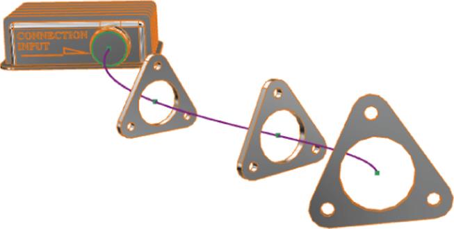
Figure 3.67 3D sketch spline
In the next section, you will add a 3D line to your 3D spline.
Using the 3D Coordinate Triad
Before continuing with the 3D sketch, take a moment to explore the 3D coordinate triad and its functionality. Each part of the triad is selectable for different tasks, as you'll see in the coming paragraphs. Figure 3.68 shows the anatomy of the triad.
1. Still in the 3D sketch, click the Line tool button on the 3D Sketch tab.
2. Notice the return of the triad and Precise Input toolbar.
3. Click the endpoint of the spline to set the start of the line on this point.
You will see the triad move to the spline endpoint. Notice that the triad is not lined up to be truly perpendicular with the bracket flange. To remedy this, you will use the Precise Redefine button found on the Precise Input toolbar. Your goal is to set the X (red), Y (green), and Z (blue) arrows of the triad to the orientation shown in Figure 3.69.
4. Select any of the arrow shafts.
5. On the Precise Input toolbar, click the Reposition Triad button, as shown at the top of Figure 3.69.
6. Select the shaft of the red X arrow and then click one of the bottom edges of the triangular flange bracket, as shown in Figure 3.69.
Note that if your X arrow faces the opposite direction, you will repeat steps 4 and 5 and select the other edge along the bottom of the bracket.
7. Next, click the Reposition Triad button again, and this time select the shaft of the green Y arrow.
8. Click one of the small edges on the sides of the flange, as shown in Figure 3.69.
Again, if the result of your selection leaves your Y arrow facing the opposite direction, you will repeat steps 7 and 8 and select another edge along the side of the bracket.
Once the triad orientation is set so that it matches Figure 3.69, you will draw a line by entering coordinates.
9. Click the triad plane between the blue and green arrows to isolate that plane to sketch on.
The triad plane should highlight red and then stay highlighted when selected (although this highlighting can be difficult to see depending on the color scheme in use). When the plane is selected, you will see a 0 placed in the X cell of the Precise Input toolbar.
10.With 0 in the X input cell, enter 300 in the Y cell, enter 25 in the Z cell, and press Enter.
Note that you can press the Tab key to switch among the X, Y, and Z input cells. Values will be input as relative coordinates. Recall that with relative coordinates, the new input coordinate point is based on the previous point rather than the absolute 0,0,0 origin point. You will now have a line running from the end of the spline out at 300 mm in the y-axis with a 25 mm rise in the z-axis.
11.Still in the Line tool, right-click and ensure that Auto-Bend is selected in the context menu. Auto-Bend will place a radius at the corners in your line route. The default radius size can be set by selecting Document Settings from the Tools tab and then selecting the Sketch tab. Once bends are placed, they can be edited like any other dimension.
12.With the Line tool still active, click the plane between the green and red arrows on the triad to isolate the XY triad plane, and enter 200 in the X input, 200 in the Y input, and leave 0 in the Z input. Press Enter on the keyboard to set this line point. You will see a small dimensioned radius at the corner of your two line segments. This is a result of the Auto-Bend option.
13.Right-click and choose Cancel to exit the Line tool. Your 3D sketch should resemble Figure 3.70.
14.Click the Dimension button in the 3D Sketch tab and add dimensions, as shown in Figure 3.71. Note that you can edit the bend radius dimension that was created with the Line tool.
15.Right-click and choose Cancel to exit the Dimension tool.
16.Right-click and choose Finish 3D Sketch.
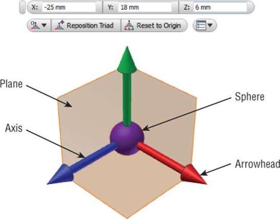
Figure 3.68 Inventor's Precise Input toolbar and the 3D coordinate triad
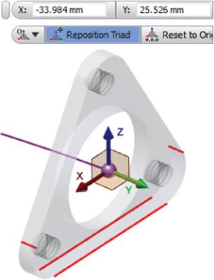
Figure 3.69 Using the Reposition Triad button to realign the triad
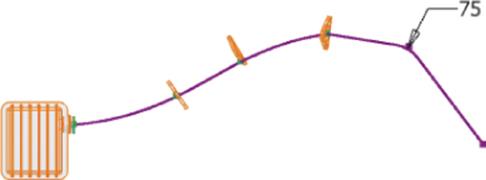
Figure 3.70 3D sketch path
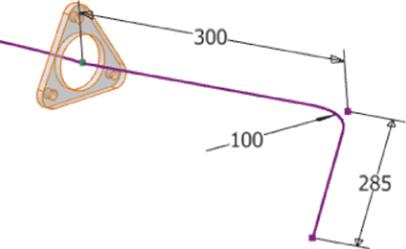
Figure 3.71 3D sketch dimensions
As a test to see whether you have successfully created your 3D sketch for its intended purpose, run a sweep along the path. Recall that there is a 2D sketch named Profile1 in the browser. This will be your sweep profile, and the 3D sketch just created will be your path.
1. In the 3D Model tab's Create panel, click the Sweep button. Profile1 will be automatically selected as the sweep profile unless you have another unconsumed, closed profile sketch in your part, in which case you will need to select Profile1 manually.
2. Once the profile has been selected, ensure that the Path button in the Sweep dialog box is enabled and then click the 3D sketch you just created. Your sweep should look like Figure 3.72.
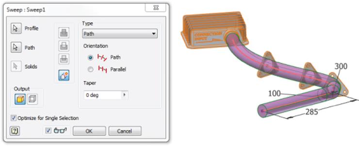
Figure 3.72 Sweeping along a 3D sketch
You will look at the Sweep tool in more depth in Chapter 5, “Advanced Modeling Techniques.” As a final note, the connection box and triangular bracket flanges have been derived into this part file as a reference feature. In the real world, once you've finished with the part, you would locate that feature in the browser and turn off the visibility. To do this, in the browser expand the feature called DerivedPart1.ipt. Right-click the feature called Derived Work Body1 and uncheck the Visibility box. If you'd like, you can save and close the part.
Exploring More 3D Sketch Tools
In addition to the Line and Spline tools used for sketching 3D geometry, several tools permit you to include and combine existing geometry to create 3D sketch elements.
Including 3D Geometry
You'll often need to use edges of parts as a path for another feature, in much the same way you project geometry in a 2D sketch. In a 3D sketch, however, you are not really projecting the geometry onto a sketch plane but simply including it for use in your 3D sketch. To see how this works, follow these steps:
1. From the Get Started tab, click the Open button.
2. Browse for the file mi_3h_017.ipt in the Chapter 3 directory of your Mastering Inventor 2015 folder and click Open.
This file has a 2D sketch named Lip Profile already created and ready to be used in a sweep feature. However, before you can do that, you'll define a path along which to sweep the profile.
3. On the 3D Model tab, select the Sketch panel and click the drop-down arrow below the Start 2D Sketch button. Then click the Start 3D Sketch button. Or right-click in an empty area of the graphics window and choose New 3D Sketch.
4. On the 3D Sketch tab, click the Include Geometry button. Next, click each edge along the curved edge, as shown in Figure 3.73, to define the sweep path.
5. Once the edges are selected, right-click and choose Finish 3D Sketch.
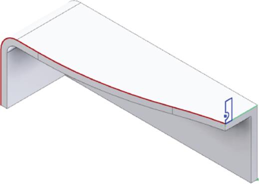
Figure 3.73 Including geometry in a 3D sketch
The path created by including geometry could not have been created with a 2D sketch because it does not exist in a single plane. You can use this path to experiment with the Sweep tool to sweep the profile along the path if you'd like. The Sweep tool is covered in more depth in Chapter 5.
Using an Intersection Curve
You can use a 3D sketch to find the intersection of two surfaces, sketch profiles, work planes, or some combination thereof. The resulting sketch is fully associative and will update automatically should the curves change. To see it in action, follow these steps:
1. From the Get Started tab, click the Open button.
2. Browse for the file mi_3h_018.ipt in the Chapter 3 directory of the Mastering Inventor 2015 folder and click Open.
3. On the 3D Model tab, select the Sketch panel and click the drop-down arrow below the Start 2D Sketch button. Then click the Start 3D Sketch button. Or right-click in an empty area of the graphics window and choose New 3D Sketch.
4. On the 3D Sketch tab, click the Intersection Curve button.
5. Click the surface and the curved face, as shown in Figure 3.74.
6. Click OK.
7. Right-click the surface and choose Visibility to toggle the visibility off. Note the resulting intersecting curve.
8. You can close the part without saving changes.
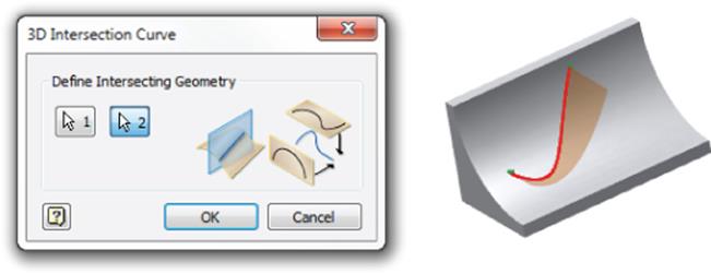
Figure 3.74 3D intersection curve
Using the Project Curve To Surface Tool
You can find intersections of curves and faces using the Project Curve To Surface tool in a 3D sketch. This tool outputs three variations of projected geometry. Geometry created using these tools will adjust if the original geometry changes. Or, if you desire, the link can be broken from the parent geometry to prevent it from adjusting automatically. To see it in action, follow these steps:
1. From the Get Started tab, click the Open button.
2. Browse for the file mi_3h_019.ipt in the Chapter 3 directory of your Mastering Inventor 2015 folder and click Open.
3. On the 3D Model tab, select the Sketch panel and click the drop-down arrow below the Start 2D Sketch button. Then click the Start 3D Sketch button. Or right-click in an empty area of the graphics window and choose New 3D Sketch.
4. On the 3D Sketch tab, click the Project To Surface button.
The first output, Project Along A Vector, requires a face, a curve, and a direction. Projecting to a continuous face such as a cylinder results in a 3D sketch entity that follows the surface as if the curve were slicing straight down through the face.
5. Click the face of the cylinder.
6. Click the Curves button. Note the Direction button, which allows you to change the projection direction. In this case, the default direction will work, so you can leave this as is.
7. Click the line on the far left.
The second output is called Project To Closest Point and projects curves in the shortest possible path normal to the surface. The result of a 3-inch line to a convex surface would be a curve less than 3 inches because the endpoints of the line would take the shortest path to the curve rather than wrapping about it.
8. In the Output area of the Project Curve To Surface dialog box, click the middle button to choose the Project To Closest Point output.
9. Click the face of the cylinder.
10.Click the Curves button.
11.Click the line in the middle.
The third output is Wrap To Surface. This output creates a curve that will be the same overall dimension as the curve from which it was created. If you wrap a string around a cylinder, the string stays the same length.
12.In the Output area of the Project Curve To Surface dialog box, click the right button to choose the Wrap To Surface output.
13.Click the face of the cylinder.
14.Click the Curves button.
15.Click the line on the right.
16.Click OK.
17.You can close the part without saving changes.
Figure 3.75 shows all three outputs; note the different outputs created from three identical lines. You can break the link of the projected curves by locating the curves in a 3D sketch from the Model browser, right-clicking them, and choosing Break Link. You must have the sketch active for edits to break the link. Doing this disallows the ability for the projected curves to update if the founding geometry is updated.
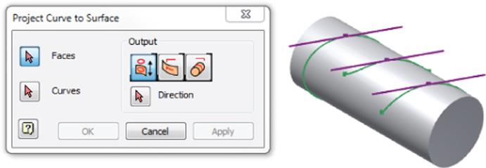
Figure 3.75 Project Curve To Surface tool
Using a Helical Curve
You can create 3D helical curves such as thread paths and coils by using the Helical Curve tool within the 3D sketch tools. Helixes can be specified by pitch and revolution, pitch and height, revolution and height, or a true spiral. A helix can be combined with other 3D sketch objects to compose as complex a path as required. Follow these steps to explore using the Helical Curve tool:
1. From the Get Started tab, click the Open button.
2. Browse for the file mi_3h_020.ipt in the Chapter 3 directory of the Mastering Inventor 2015 folder and click Open.
3. Notice the existing 2D sketch consisting of a single line.
4. On the 3D Model tab, select the Sketch panel and click the drop-down arrow below the Start 2D Sketch button. Then click the Start 3D Sketch button. Or right-click in an empty area of the graphics window and choose New 3D Sketch.
5. On the 3D Sketch tab, click the Helical Curve button.
6. For the start point, select one end of the line.
7. Select the other end of the line for the endpoint of the helical curve.
8. Click in the graphics window to rough in the diameter.
9. Set the precise diameter value to 25 mm, as shown in Figure 3.76.
10.Enter 10 mm for the pitch.
11.Enter 5 for the revolutions.
12.Click OK.
13.Examine the resulting helical curve, as shown in Figure 3.76.
14.Note that you can change the inputs of the curve by right-clicking it and choosing Edit Helical Curve.
15.You can close the part without saving changes.
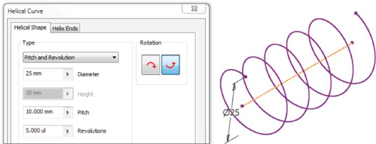
Figure 3.76 A helical curve
Using a Silhouette Curve
You can create an associative 3D curve along the outer boundary of a body as defined by a selected direction. Imagine a beam of light cast on an object from a single direction. The curve created where the shadow line begins would be the silhouette curve. You can use the Silhouette Curve tool to determine the parting line of organic shapes; just follow these steps.
1. From the Get Started tab, click the Open button.
2. Browse for the file mi_3h_021.ipt in the Chapter 3 directory of the Mastering Inventor 2015 folder and click Open.
3. On the 3D Model tab, select the Sketch panel and click the drop-down arrow below the Start 2D Sketch button. Then click the Start 3D Sketch button. Or right-click in an empty area of the graphics window and choose New 3D Sketch.
4. On the 3D Sketch tab, click the Silhouette Curve button.
5. For the Body selection, click anywhere on the part.
6. For the Direction selection, click the work axis.
7. Click OK. Note the resulting curve, as shown in Figure 3.77. You can exit the sketch and close the file when finished.
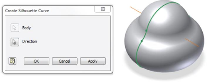
Figure 3.77 A silhouette curve
You can break the link of the projected curves by locating the curves in a 3D sketch from the Model browser, right-clicking them, and choosing Break Link. Doing this disallows the projected curves to update if the founding geometry is updated.
Refining and Constraining a 3D Sketch
You can anchor and constrain a 3D sketch in much the same fashion as you do a 2D sketch using dimensions and constraints. Additionally, with 3D splines you can add vertex points and control curve fit with handles. Further refining can take place because you can adjust the fit method and spline tension to create the exact curve shape desired.
Best Practices for Working with Sketches
Here is a list of points to remember as you continue working with sketches in Inventor. Keep in mind that sketches are the foundation for good modeling, and therefore the importance of creating stable, fully constrained sketches cannot be overstated.
· Keep sketches simple.
· Your goal should always be to have a fully dimensioned and constrained sketch.
· Sketches that are not fully constrained tend to distort unpredictably when you make modifications and updates.
· Rough out size and shape before adding dimensions and constraints to avoid distorting the sketch when dimensions and constraints are added.
· Add dimensions to lock down shape and then come back to change the size.
· Endpoint, midpoint, center, and intersection snap points can be helpful when creating sketch entities, but be aware of how they affect dimensions compared to selecting the line itself rather than the snap points.
· You can use the Backspace key to clear the last-selected points. For instance, if you select a point for the end of a line and then realize you should have selected another point instead, use the Backspace key to clear the first selection and then start the line where it should have been.
· Use centerlines to define revolution axes and diametric dimensions.
· Use construction lines to further define sketches and create “helper” geometry.
· When you need to select multiple sketch entities, you can use a crossing selection or a window selection. A crossing selection is created from right to left and selects any object that is touched or contained by the window. A window selection is created from left to right and selects only objects that are completely contained in the window.
· Use the Delete key on the keyboard to quickly remove accidentally created geometry.
· Use the Split tool rather than the Trim tool when you can because the Split tool does not break previously defined constraints.
· Turn off automatic edge projection to avoid extra sketch geometry and project only the edges you need. This will make sketches easier to edit.
· Reserve fillets and chamfers for the feature level whenever possible. Although you can fillet and chamfer at the sketch level, it is generally best to keep your sketches simple and fillet and chamfer the solid features rather than the sketches.
· You can create pattern and mirrored geometry in the sketch, but it is generally best to make a simple sketch, then create a feature from it, and finally pattern or mirror the feature. The results are often the same, but the feature patterns are much easier to edit.
The Bottom Line
1. Set up options and settings for the sketch environment. Understanding the settings and options that apply to the sketch environment is an essential first step in working with Inventor.
1. Master It You want to configure your own set of options and settings for your sketch environment and then back them up and/or distribute them to other workstations. How would you do this?
2. Create a sketch from a part file template. Creating a sketch in a blank template file is the fundamental step in creating 3D parametric models. You will use this basic step to start most of your part designs.
1. Master It How would you capture the intent of your design when creating a base sketch for a new part?
3. Use sketch constraints to control sketch geometry. Understanding what each sketch constraint does when applied will allow you to determine when to use each type. Recall that often more than one constraint will work in any given situation.
1. Master It How would you create a sketch that allows you to test “what if?” scenarios concerning the general shape and size of your part?
4. Master general sketch tools. Learning the features and tricks of the sketch tools will allow you to master Inventor sketching.
1. Master It You are given a print of mixed units to work from, and you need to enter dimensions exactly as they are on the print. You understand that you can enter any dimensions in any unit simply by adding the correct suffix. But how would you create a radius dimension on a circle or a dimension from the tangents of a slot?
5. Create sketches from AutoCAD geometry. You can use existing AutoCAD files to create a base sketch for an Inventor model of the same part.
1. Master It You have many existing 2D AutoCAD drawings detailing legacy parts. You want to reuse these designs as you convert to 3D modeling. How would you proceed?
6. Use 3D sketch tools. Much of working with a 3D parametric modeler can be done by sketching in a two-dimensional plane and then giving depth to the sketch to create 3D features. However, sometimes you need to create paths or curves that are not planar. In those cases, you use the 3D sketch tools.
1. Master It You know the profile of a complex curve as viewed from the top and side. How would you create a 3D sketch from this data?