COLLABORATIVE INTERNET OF THINGS (C-IOT). FOR FUTURE SMART CONNECTED LIFE AND BUSINESS (2015)
3
C-IoT Applications and Services
In this chapter, we describe some Collaborative Internet of Things C-IoT applications and services that span multiple domains, from personal consumer to home to industrial (business) and smart city (infrastructure and communities) levels to deliver sustainable smart living and smart environment that help optimize business process efficiency and improve quality of life, see Figure 3.1.
1. Smart living (Consumer)
a. Smart connected consumer – tracking and fitness/health monitoring
b. Smart connected home
c. Smart connected car, transport
2. Smart industry (Business)
a. Smart industrial (factories, buildings, smart grid/energy, retail, manufacturing)
b. Smart agriculture
3. Smart infrastructure (city and communities) and sustainable smart environments.
Here are some quotes regarding the impacts of the IoT (Internet of Things) markets and services.
· Home and Building Automation. Digital marketer Lauren Fisher points to the Nest Learning thermostat, which takes data about the home environment and owners’ temperature preferences and programs itself to operate efficiently within the context of that information. This technical framework provides energy providers with the connectivity to better manage the energy grid.
· Smart Car. Mobile virtual network operator Alex Brisbourne describes how the automotive industry is increasingly designing automated applications into vehicles to provide maintenance monitoring, fuel and mileage management, driver security, and other capabilities that cost little to integrate but have significant earning potential. The addition of a cloud-based server to analyze the data and automatically act on it – automatically scheduling a maintenance appointment at the appropriate time, for example – would move this further in the direction of the IoT.
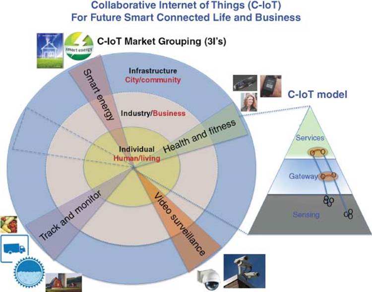
Figure 3.1 IoT markets
· Smart Transportation/Smart Cities. Technology writer Martyn Casserly cites the London iBus system, which “…works with information from over 8000 buses that are fitted with global positioning system (GPS) capabilities alongside various other sensors which relay data about the vehicle’s location and current progress,” so bus stop signposts can display details of a bus’s impending arrival.
IoT concepts have already been adopted in areas such as “energy (e.g., smart lighting and smart grid) and industrial automation… essentially whatever is connected to or crosses over the Internet.” Cisco estimates the Internet of Everything (IoE) to be worth $14.4 trillion to the global economy by 2020.
3.1 Smart IoT Application Use Cases
This chapter explains several use case examples to demonstrate smart IoT systems with interoperability among smart devices to improve quality of life and business process efficiency [1, 2]. These IoT products for various IoT businesses can be deployed using a unified, secured, smart IoT software platform consisting of the IoT Gateway Platform [3] and Sensor Fusion Platform [4] which will be described after the IoT use case examples [5].
There are three scalable domains (3I’s) of influence with IoT products. Each IoT product for a certain business can span three domains.
The first domain, namely, Individual (Consumer) IoT level, Smart Connected Human living in a Smart connected Home will contribute toward improving quality of life in Smart Living. Applications from radio frequency identification (RFID) tracking of kids and pets to health fitness monitoring to smart thermostat in a smart home, all contribute to an improved lifestyle.
The second domain is Industrial IoT, from smart RFID in fleet tracking logistics to Smart Video security surveillance to active security systems with object recognition to smart energy meters to improve business process efficiency in Smart Business.
The third domain is the Infrastructure IoT for our city, community, and environment, to show how smart sensors operate together in our community infrastructure to improve our quality of life and sustainability of our smart city and smart world.
Many IoT business applications cross all three domains. Examples of these applications include video surveillance, smart energy, smart home/buildings, smart health, as well as tracking and monitoring of assets.
Motivation for C-IoT is the delivery of IoS (Internet of Service) (Figure 3.2). This chapter describes how embedded things can be connected to the cloud via the smart IoT gateway software platform for delivery of IoS business. Smart things (things with smart sensors and microcontrollers) are connected to the cloud (optionally via smart wireless gateways). IoS is an end-to-end system integration that delivers business services via the cloud, which utilizes a sensor-fusion software platform to perform data analytics and for decision making; automated actions and business services are thereby taken as part of streaming a business process. This referred to as B2C2T2B (Business to Consumer to Things to Business).
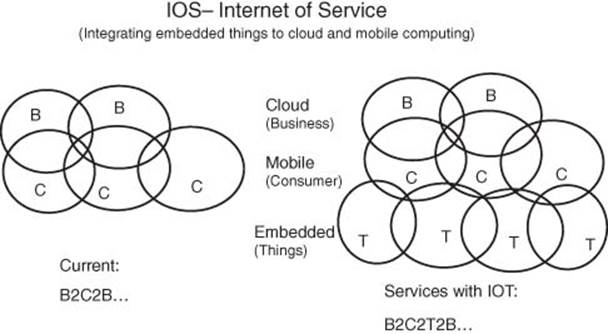
Figure 3.2 Internet of service (IOS) – integrate embedded things to cloud and mobile
3.1.1 Health Monitoring – Individual Level (Fitness/Health-Tracking Wearables)
These small consumer devices come in the form of smart bracelets, smart watches, smart eye-glasses, smart T-shirts, or smart shoes equipped with location sensors (RFID, near field communication (NFC), GPS) that track assets (kids, pets, elderly) as well as sensors for tracking health fitness biometrics (pulse, blood pressure, temperature, pedometer, accelerometer, etc.). The Go-Pro comes with a Wi-Fi camera mounted on a cap that capture actions using an MPU microprocessor unit to stream the video to smartphones/tablets which in turn can stream this to the cloud for sharing with friends. These devices are equipped with low-power microcontroller units (MCUs) which perform the data acquisition function and transmit the sensing data via Bluetooth Low-Energy BLE (BT4.0) wireless connectivity to a smartphone or PC which ultimately transmits the sensing data onto the cloud for Big Data analytics and storage, thus allowing remote monitoring and tracking control.
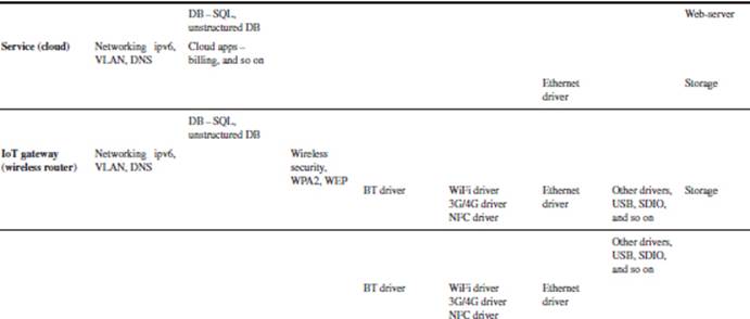
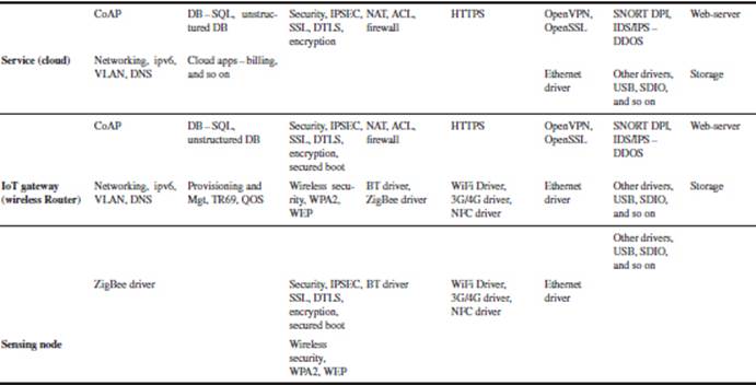
The smart wearable fitness in Figure 3.3 shows an activity monitoring bracelet that contains an accelerometer and transmits its data to an intermediate gateway such as a smartphone or PC via Bluetooth BLE (BT4.0). The data are then transmitted to the Internet server for Big Data analytics. The summary trend analysis report is then accessible via the individual’s smartphone. Table 3.1 shows software stacks for smart wearable health fitness/monitoring.
The wearable device usually pairs with the smartphone/smart tablet to act as an IoT gateway that aggregates the sensing data and transmits them to the cloud.
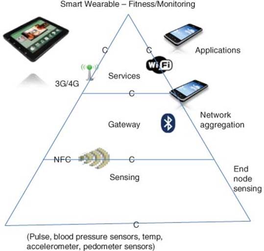
Figure 3.3 Heath fitness monitoring
Table 3.1 Software stacks for heath fitness monitoring
A Machine-to-Machine (M2M) Gateway (sometimes referred to as data aggregator or concentrator) is used to provide connectivity among multiples sensor end nodes and multiple users. An IoT Gateway is essentially an M2M Gateway with added cloud (Internet network) connection that facilitates Big Data analytics and remote monitoring/control.
A fitness activity monitoring bracelet can also connect to other fitness devices such as a smart weight scale that monitors body weight, body fat, so the consumer’s weight and fat are connected to the fitness monitoring database for more accurate computing of factors such as calorie consumption.
Another form of wearable is the smart watch, which can include camera, accelerometer, thermometer, altimeter, barometer, compass, chronograph, calculator, cell phone, touch screen, GPS navigation, Map display, graphical display, speaker, scheduler, and watch functions. A smart watch usually has NFC functionality that can pair with a smartphone for data exchange synchronization with the smartphone.
When these portable devices are equipped with RFID, GPS, and so on, they become useful for tracking and monitoring of assets in addition to fitness monitoring. Location tracking can also be implemented using BLE and/or low-power Wi-Fi for lower power, long battery life operation. Tracking of assets can be done at consumer level (kids, pets, elderly) at business and industry level (goods and cargo), and also in transportation logistics (taxis, trucks) at industrial and city infrastructure level. Asset monitoring and tracking can also be applied to agriculture such as to monitor the health of livestock and vegetation which includes automation of irrigation, feeding, and fertilization.
A smart wearable device can be evaluated by the following 8A’s:
8A’s: Automated Remote Provisioning and Management, Augmented Reality Human–Machine Interface HMI, Awareness of Context and Location, Analyze and Take Action, Automate, Anticipate, and Predict, Autonomous, Attractive
· Automated Install. This is usually a USB-based auto-install using a PC.
· Augmented Reality and HMI (human–machine interface). This usually has limited user-interface and display.
· Awareness of Context and Location. They usually lack awareness of context and location.
· Analyze and Take Action. Smart wearables usually have limited analysis capability and usually transmit sensing data to the Internet (cloud) for analysis.
· Automate. They have limited automation capability.
· Anticipate and Predict. Again, this is usually based on cloud-based analysis of data trend with limited predictive analysis capability.
· Autonomous. They involve limited rule-based intelligence and do not collaborate with other smart devices in the environment.
· Attractive and Esthetic. Smart wearables usually have good aesthetics, look, and feel.
3.1.1.1 Next Generation Smart Wearable and Automation Devices
Future Smart IoT systems will be more interoperable to create more conscious and thoughtful home operation and take connected intelligence to the next level of collective intelligence.
The smart wearable will interoperate with the smart thermostat to offer further context aware operation and take connected intelligence to the next level of collective intelligence.
For example, a fitness wristband’s motion sensor could be used to detect that the owner is awake and trigger the smart thermostat to turn on the heating system.
The smart video camera could provide the smart thermostat a customized context control regarding who is at home.
3.1.2 Health Monitoring at Business Level (e.g., Clinic and Homes for the Elderly)
3.1.2.1 M2M in Healthcare
Within an aging population, an increase in monitored illnesses such as diabetes and heart disease and insurance mandates around hospital stays and visits has led to an increase in home-based health monitoring [6]. This is now being matched by the onset of portable devices, which monitor patients away from a hospital or physician’s office. Cost savings match the added comfort of the patient for healthcare providers and insurers. Devices that monitor a patient’s vital signs at home can operate as a direct M2M device via a gateway of the type mentioned in the previous M2M at Home section, or a dedicated telehealth hub. In either case, measured data such as blood pressure, heart rate, body temperature, respiratory rate, blood glucose, and cholesterol can be accumulated, processed and, if desired, sent periodically to the healthcare provider. Numerous MPU microprocessors are enabled with trust architecture and encryption acceleration hardware which help provide a secure encrypted communication link between patient and physician ensuring that private information does not get stolen.
In the IoT, devices gather and share information directly with each other and connect to the cloud, making it possible to collect, record, and analyze new data streams faster and more accurately. That suggests all sorts of interesting possibilities across a range of industries: cars that sense wear and tear and self-schedule maintenance or trains that dynamically calculate and report projected arrival times to waiting passengers.
But nowhere does the IoT offer greater promise than in the field of healthcare, where its principles are already being applied to improve access to care, increase the quality of care and most importantly reduce the cost of care. A telehealth product delivers care to people in remote locations and monitoring systems that provide a continuous stream of accurate data for better care decisions.
As the technology for collecting, analyzing, and transmitting data in the IoT continues to mature, we will see more and more exciting new C-IoT-driven healthcare applications and systems emerge. Read on to learn what is happening now – and what is on the horizon – for healthcare in the age of the IoT.
There is no shortage of predictions about how C-IoT is going to revolutionize healthcare by dramatically lowering costs and improving quality. Wireless sensor-based systems are at work today, gathering patient medical data that was never before available for analysis and delivering care to people for whom care was not previously accessible. In these ways, C-IoT-driven systems are making it possible to radically reduce costs and improve health by increasing the availability and quality of care.
An IoT-driven healthcare monitoring system includes
· Sensors that collect patient data
· Microcontrollers that analyze and wirelessly communicate the data
· Microprocessors that enable rich graphical user interfaces (GUIs)
· Healthcare gateways-analyzed sensor data that are sent to the cloud.
3.1.2.2 Understanding C-IoT
C-IoT-related healthcare systems today are based on the essential definition of the IoT as a network of devices that connect directly with each other to capture and share vital data through a secure socket layer (SSL) that connects to a central command and control server in the cloud. Let us begin with a closer look at what that entails and what it suggests for the way people collect, record, and analyze data – not just in healthcare, but in virtually every industry today.
The idea of devices connecting directly with each other is, as the man who coined the term Internet of Things puts it, “a big deal.” As Kevin Ashton explained a decade after first using the phrase at a business presentation in 1999, “Today computers – and therefore, the Internet – are almost wholly dependent on human beings for information. The problem is, people have limited, time, attention, and accuracy – all of which means they are not very good at capturing data about things in the real world.” The solution, he has always believed, is empowering devices to gather information on their own, without human intervention.
The following are two important reasons for devices to connect directly to data and to each other:
1. Advances in sensor and connectivity technology are allowing devices to collect, record, and analyze data that was not accessible before. In healthcare, this means being able to collect patient data over time that can be used to help enable preventive care, allow prompt diagnosis of acute complications, and promote understanding of how a therapy (usually pharmacological) is helping improve a patient’s parameters.
2. The ability of devices to gather data on their own removes the limitations of human-entered data – automatically obtaining the data physicians need, at the time and in the way they need it. The automation reduces the risk of error. Fewer errors can mean increased efficiency, lower costs, and improvements in quality in just about any industry.
3.1.2.3 C-IoT in Action in Healthcare
C-IoT plays a significant role in a broad range of healthcare applications, from managing chronic diseases at one end of the spectrum to preventing disease at the other. Here are some examples of how its potential is already playing out:
1. Clinical Care. Hospitalized patients whose physiological status requires close attention can be constantly monitored using C-IoT-driven, noninvasive monitoring. This type of solution employs sensors to collect comprehensive physiological information and uses gateways and the cloud to analyze and store the information and then send the analyzed data wirelessly to caregivers for further analysis and review. It replaces the process of having a health professional come by at regular intervals to check the patient’s vital signs, instead providing a continuous automated flow of information. In this way, it simultaneously improves the quality of care through constant attention and lowers the cost of care by eliminating the need for a caregiver to actively engage in data collection and analysis.
An example of this type of system is the Massimo Radical-7 , a health monitor for clinical environments that collects patient data and wirelessly transmits for ongoing display or for notification purposes. The results provide a complete, detailed picture of patient status for clinicians to review wherever they may be. The monitor incorporates an embedded processor with enhanced graphics capabilities that enables extremely high-resolution display of information, as well as a touch-based user interface (UI) that makes the technology easy to use.
3.1.2.4 Remote Patient Monitoring
There are people all over the world whose health may suffer because they do not have ready access to effective health monitoring, see Figure 3.4. But small, powerful wireless solutions connected through C-IoT are now making it possible for monitoring to come to these patients instead of vice versa. These solutions can be used to securely capture patient health data from a variety of sensors, apply complex algorithms to analyze the data and then share these through wireless connectivity with medical professionals who can make proper health recommendations.
As a result, patients with chronic diseases may be less likely to develop complications, and acute complications may be diagnosed earlier than they would be otherwise. For example, patients suffering from cardiovascular diseases who are being treated with digitalis could be monitored around the clock to prevent drug intoxication. Arrhythmias that are randomly seen on an EKG could be easily detected, and EKG data indicating heart hypoxemia could lead to faster detection of cardiac issues. The data collected may also enable a more preventive approach to healthcare by providing information for people to make healthier choices.
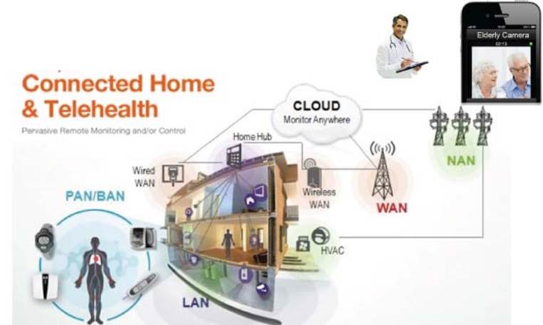
Figure 3.4 Remote patient monitoring
An example of an enabling technology for remote monitoring is a Home Health Hub (HHH) Gateway reference platform, (Figure 3.5) built on an embedded processor, integrating with wireless connectivity and power management – in the telehealth gateway that enables collection and sharing of physiological information. The hub captures patient data from a variety of sensors and securely stores it in the cloud, where it can be accessed by those engaged in the patient’s care. Data aggregation devices like this will soon become commonplace and will not only collect healthcare data but also manage other sensor networks within the home. In addition to healthcare data, this gateway manages data from smart energy, consumer electronics, and home automation and security systems.
Early intervention/prevention: Healthy, active people can also benefit from C-IoT-driven monitoring of their daily activities and well-being. A senior living alone, for example, may want to have a monitoring device that can detect a fall or other interruption in everyday activity and report it to emergency responders or family members. For that matter, an active athlete such as a hiker or biker could benefit from such a solution at any age, particularly if it is available as a piece of wearable technology.
These are just a few examples of C-IoT-based healthcare solutions, and many more are emerging. But as one reporter has noted, “The real vision for the future is that these various smaller applications will converge to form a whole.… Imagine if you are a relative of [a] patient who forgot their medicine. You receive the alert, are able to know their location, check their vital signs remotely to see if they are falling ill, then be informed by your car’s navigation system which hospital has the most free beds, the clearest traffic route to get there and even where you can park.”
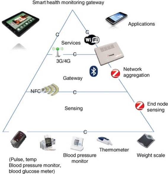
Figure 3.5 Smart health monitoring platform (e.g., clinic and elderly homes)
3.1.2.5 Enabling Technologies: Making C-IoT in Healthcare Possible
The successful use of C-IoT in the preceding healthcare examples relies on several enabling technologies. Without these, it would be impossible to achieve the usability, connectivity, and capabilities required for applications in areas such as health monitoring.
Figure 3.6 shows a Smart Health Monitoring Platform used for clinics or in homes for the elderly.
Smart sensors, which combine a sensor and a microcontroller, make it possible to harness the power of C-IoT for healthcare by accurately measuring, monitoring, and analyzing a variety of health status indicators. These can include basic vital signs such as heart rate and blood pressure, as well as levels of glucose or oxygen saturation in the blood. Smart sensors can even be incorporated into pill bottles and connected to the network to indicate whether a patient has taken a scheduled dose of medication.

Figure 3.6 Home health hub
For smart sensors to work effectively, the microcontroller components must incorporate several essential capabilities:
· Low-power operation is essential to keeping the device footprint small and extending battery life, characteristics that help make IoT devices as usable as possible. In the future, there will be more low-power processors that will be battery-free devices that utilize energy harvesting techniques through the use of ultra-low-power DC–DC (direct current) converters.
· Integrated precision-analog capabilities make it possible for sensors to achieve high accuracy at a low cost by selecting microcontrollers with high-resolution analog-to-digital converters (ADCs) and low-power op-amps.
· GUIs improve usability by enabling display devices to deliver a great deal of information in vivid detail and by making it easy to access that information.
Gateways are the information hubs that collect sensor data, analyze and then communicate the data to the cloud via wide area network (WAN) technologies. Gateways can be designed for clinical or home settings; in the latter, they may be part of larger connectivity resource that also manages energy, entertainment, and other systems in the home. Medical device designers can also use the platform to create remote-access devices for remote monitoring.
Wireless networking removes the physical limitations on networking imposed by traditional wired solutions such as the Ethernet and USB. MCUs and MPUs that support wireless connectivity for devices based on popular wireless standards such as Bluetooth and BLE for personal area networks (PANs) are used with personal devices and Wi-Fi and Bluetooth for local area networks (LANs) in clinics or hospitals. That leads us to a key challenge for the IoT in healthcare: standards.
3.1.2.6 Connectivity Standards: Enabling C-IoT Devices to Work Together
Standards represent an inherent challenge for any environment in which a large number of complex devices need to communicate with each other – which is exactly the case for C-IoT in healthcare. One analyst has described the “… greater standardization of communications protocols…” as critical to advancing the adoption of C-IoT.
Fortunately, standards organizations are working now to create guidelines for wireless communications between monitoring devices and with care providers. The Continua Health Alliance is a coalition of healthcare and technology companies that was founded in 2006 to establish guidelines for interoperable personal health solutions. The organization has already published a set of specifications to help ensure interoperability. In the future, organizations that buy a Continua Certified® device will have the assurance that it will connect with other certified devices in IoT-driven applications. Continua’s device standards are part of a larger standards environment that includes information technology standards established by the International Organization for Standardization (ISO) and engineering standards set by the Institute of Electrical and Electronics Engineers (IEEE®).
In wireless technology, IEEE standards for LANs define Wi-Fi (IEEE 802.11) and ZigBee® (IEEE 802.15.4) networks. Standards for PANs include Bluetooth and BLE, as well as IEEE 802.15.4j and IEEE 802.15.6, which are the IEEE standards associated with the body area network (BAN). Standards for cellular networks include GSM/UMTS and CDMA. Proprietary wireless networks still play something of a role in healthcare environments in general and IoT applications in particular, but that role seems to be shrinking as the industry continues to move toward standards-based architectures.
3.1.2.7 C-IoT in Healthcare
The long-predicted C-IoT revolution in healthcare is already underway, as the examples in this chapter make clear. And, those are just the tips of the proverbial iceberg, as new use cases continue to emerge to address the urgent need for affordable, accessible care. Meanwhile, we are seeing the C-IoT building blocks of automation and M2M communication continue to be established, with the addition of the service layer completing the infrastructure.
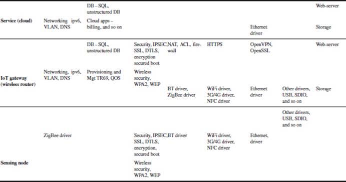
Table 3.2 shows the software stacks for a Health Monitoring Platform used for clinics or elderly homes.
Table 3.2 Smart health monitoring platform
3.1.2.8 Home Health Hub (HHH)
The HHH (Figure 3.6) reference platform provides seamless connectivity with commercially available wired and wireless healthcare devices, such as blood pressure monitors, pulse oximeters, weight scales, and blood glucose monitors [7]. The data obtained from these devices is then relayed via Wi-Fi and 3G Broadband to a remote device, such as a smartphone, tablet, or PC, in order to track and monitor a patient’s health status as well as provide alerts and medication reminders.
The display interface also provides a real-time connection to caregivers, including family, friends, and physicians, to bring peace of mind and safety to the person being monitored.
The HHH reference platform features a low-power embedded processor, a ZigBee® transceiver, and a sub-gigahertz radio transceiver used for a panic alarm sensor, providing personal emergency response system (PERS) functionality and enabling remote healthcare device monitoring.
3.1.2.9 Features Benefits
· The development and demonstration platform includes a gateway and a panic alarm sensor.
· The platform supports rapid prototyping, reducing time to market, and focusing resources on differentiation.
· Prevalidated USB, BT, BLE, Wi-Fi, ZigBee connectivity including medical class grades are available.
· The platform allows for connectivity to medical devices and sensors for automatic reporting and monitoring of vital sign measurements and implementation of daily activity alarms, and alarms for early detection of injury or security risks.
· Connectivity is available via Wi-Fi and Ethernet to external smart devices (tablet, smartphone, PC) along with a compelling UI for remote display.
· The platform offers anytime access and consultation to trusted health resources, medical staff, and family and friends through an intuitive and simple to use interface.
3.1.2.10 HHH Reference Platform Kit Contents
· HHH gateway printed circuit board (PCB)
· BT/Wi-Fi module (connects to the HHH Gateway PCB)
· Panic alarm sensor
· Quick start guide
· Windows Embedded Compact 7, Linux, Java frameworks with example code
· ZigBee Healthcare and Home Automation stacks
· Bluetooth HDP and Low-Energy stacks (subject to license from Stonestreet One)
· USB PHDC stack
· Wi-Fi stack
· Design files
· Cables.
3.1.3 Home and Building Automation – Individual Level (Smart Home)
3.1.3.1 Smart Thermostat (Smart Energy Management)
A smart thermostat replaces the traditional digital thermostat that has a fixed program by having added cloud connectivity for remote provisioning and updates, and by supporting remote monitoring and control via smartphones/tablets. A smart thermostat in the future could also act as a wireless gateway that interconnects other personal and home automation devices through a ZigBee-based wireless sensor network (WSN).
Here is an evaluation of Nest’s Smart Thermostat with respect to the 8A’s:
8A’s: Automated Remote Provisioning and Management, Augmented Reality Human – Machine Interface HMI, Awareness of Context and Location, Analyze and Take Action, Automate, Anticipate, and Predict, Autonomous, Attractive
Automated Provisioning. The Nest Smart Thermostat is simple, intuitive, and easy to use, as it has a self-learning install and adaptive setup mode; it learns your preferred temperature settings during weekdays and weekends with its auto-schedule mode. One aspect of the self-learning is keeping track of Time-to-Temp, whereby it learns how long it takes your home to heat up and cool down, so it will get ready ahead of time before the present time of desired temperature. It will turn off the furnace but leave the fan on long enough to maximize heat distribution without wasting energy. This smart device is Internet connected.
· Automated Updates. It receives automated software updates as it becomes more intelligent. The cloud connection provides remote monitoring and controlability through smartphones/tablets.
· Automated. It is automated with multiple sensors such as temperature, humidity, ambient light, infrared motion, proximity short range, and long-range activity sensors.
· Analyze and Take Action. The humidity sensor can trigger humidifier to turn on, as the air starts getting dry.
· Aware of Context and Location. The auto-away mode is context aware with a motion sensor that can detect if people are around, and avoid wasting energy heating or cooling an empty house. It also leverages the Internet location-aware weather condition outside the home and customizes the heating and cooling accordingly.
· Anticipate and Predict: Autonomous Action. It is interoperable with smartphones/tablets and other devices such as the Nest Protect smoke alarm. It has an auto-tune mode that automatically makes adjustment to lower energy consumption while keeping you comfortable. For example, its airwave mode automatically runs the alternating current (AC) less when humidity is not too high and ensures that you stay cool. It is provided with a “filter reminder” to remind you of the time for preventive care to replace the air filter. It could also remind you when to perform an AC tune-up.
· Attractive. It is easy on the eyes, with a stainless steel benzyl that reflects the surrounding wall color. A glass LCD display shows feedback regarding operating modes (red for heating) and efficiency (green leaf when it is saving energy).
The round benzyl is a scroll wheel that can be turned like a trackball and the magneto sensor provides accurate menu location selection.
This smart device is secured with WEP, WPA2, HTTPS, SSL, and 128-bit encryption.
Next-Generation Smart Thermostat and Home Automation Devices
Future smart C-IoT systems will be more interoperable to create more conscious and thoughtful home operation and take connected intelligence to the next level of collective intelligence.
For example, a Fitbit or Jawbone fitness wristband’s motion sensor could be used to detect that the owner is awake and trigger the smart thermostat to turn on the heating system. When you leave home, your smart garage door openers could trigger your smart thermostat to a lower setting once you have left. As your car approaches home, your car can trigger the smart thermostat to turn on the heating, ventilation, and air-conditioning (HVAC). Your smart smoke alarm could trigger your LED lighting to flicker on lighting in addition to just the alarm. Your smart thermostat, while in the auto-away mode, can randomly turn on/off lighting while you are away from home.
The smart thermostat will interoperate with the smart IP camera to offer further context-aware operation and take connected intelligence to the next level of collective intelligence.
The smart video camera such as the “Dropcam” for surveillance could provide the smart thermostat a customized context control regarding who is at home.
3.1.3.2 Smart Smoke Alarm (Safety)
The Nest Protect smoke alarm is another smart home device from Nest Lab. It is equipped with a photoelectric smoke sensor, a carbon monoxide sensor, a heat sensor, activity sensors, a humidity sensor, and an ambient light sensor. The Nest Protect smoke alarm can interoperate with a Nest thermostat. Nest Protect uses a lower-power 100 MHz Cortex M3. A smart smoke alarm also has multiple LED light display feedback, such as white light to indicate automatic night light, green to indicate all is clear, yellow to indicate early warning, and red for emergency and evacuation. The motion detector is used to detect directed arm-waving to silence the alarm.
3.1.3.3 Smart IP Camera for Video Surveillance (Security)
The “Dropcam” wireless IP camera, an example for video monitoring at homes and small businesses, is a dual-band (2.4 and 5 GHz) wireless IP camera with cloud-based SSL-encrypted video recording service using AWS (Amazon Web Service), which now records more videos than YouTube. This is an HD720p camera with night vision, 8× zoom, 130° viewing, two-way talk (mic and speaker), smart alerts (activity recognition based on motion and audio), and location aware.
Here is an evaluation of Dropcam with respect to the 8A’s:
8A’s: Automated Remote Provisioning and Management, Augmented Reality Human-Machine Interface HMI, Awareness of Context and Location, Analyze and Take Action, Automate, Anticipate, and Predict, Autonomous, Attractive
· Automated Provisioning. The Wi-Fi IP-camera has an easy setup wizard, Bluetooth (BT) pairing connectivity is provided, so one can even install the IP-camera via a smartphone.
· Automated. Smart alerts – activity recognition based on motion and audio.
· Analyze and Take Action. The Dropcam Pro has a pattern recognition video analytic feature to track custom rules. For example, you might set the tab to send an alert to your mobile phone when the front door is opened or when the TV or the desktop PC is moved.
· Aware of Context and Location. Turns camera on and off depending on where the owner is located and has the optional motion detect sensor “Dropcam Tab” which can be placed at a window or door within 100' from the Dropcam camera.
· Secure. The video is SSL (Secured socket layer)-encrypted, and one can sign up for cloud-based video recording service.
· Attractive. It is easy on the eyes.
Next-Generation Smart IP Surveillance Camera and Home/Building Automation Devices
The Smart IP camera will interoperate with the Smart Thermostat to offer further context-aware operation and take connected intelligence to the next level of collective intelligence.
Your smart video camera could provide the Smart Thermostat a customized context control regarding who is at home.
Video monitoring is used in home and public security in retail, banks, ATMs, school, traffic monitoring, transport safety, as well as in factory and manufacturing automation such as machine vision in robotics for automated assembly and automated assembly inspection. Smart video analytic software is added for smart video monitoring with facial recognition, license-plate recognition, automated assembly inspection, and so on.
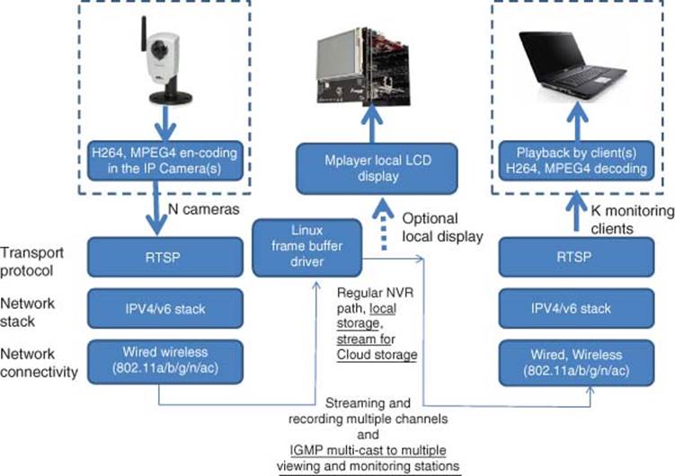
Figure 3.7 Video surveillance and network video recording (NVR) architecture
Video Surveillance and Machine Vision at Industrial Market and Infrastructure Level
Video surveillance uses an NVR (Network Video Recorder) as shown in Figure 3.7. Video surveillance and NVR is a scalable approach to scale for implementing security at buildings, factories, and city level [8].
Table 3.3 shows software stacks for video surveillance and NVR.
Figure 3.8 illustrates video surveillance and NVR. The architecture, showing numerous IP cameras (~64 cameras), usually streams to a video server called the Network Video Recorder for video recording of camera streams and for easy communication with automation systems (SCADA-supervisory control and data acquisition). The IP cameras can send event tags to the automation system with system information and the status of each channel. In addition, the video server can receive event tags sent from the automation system to trigger video recording and other actions.
Table 3.3 Video surveillance and network video recording (NVR)
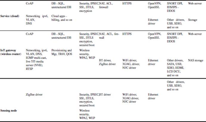
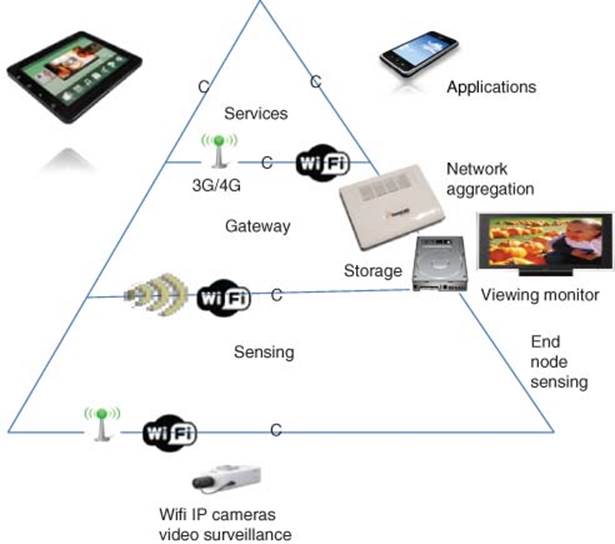
Figure 3.8 Video surveillance and network video recording (NVR)
Other features are as follows:
· remote live multi-cast viewing and remote playback via web access of transcoded videos with H.264, MPEG4, and MJPEG formats;
· intelligent key frame to decode only to save system resources for higher priority tasks;
· video recording with manual, event-triggered, and scheduled recording;
· playback system with event- and time-based search functionality;
· video analytics with face recognition, license-plate recognition, and so on.
3.1.3.4 Service Robots at Consumer Level – Roomba iRobot
Another Smart home device is the Roomba vacuum cleaning robots from iRobot which also showcase integration of a rich set of smart software with sensors. Other home service robots for autonomous home automation can automate house chores such as mopping the floor, cleaning windows, pool cleaning, and mowing the lawn. These service robots are equipped with rich sets of sensors such as Vision Camera, Ultrasonic, Infrared (IR) sensor, Obstacle IR Sensor, Dirt Detection Sensor, Battery Status Sensor, Optical Floor Sensor, Gyro, and Accelerometer and integrated with the following sophisticated smart software. Roomba by itself is just an M2M automation device without cloud interface. However, the Roomba community and enthusiasts have developed after-market Wi-Fi cloud remote enable controls, which extend it to be more C-IoT worthy. These smart service robots can be more context-ware to clean the room only when you are not in the room and when the owners are not asleep, as indicated by their fitness wristband.
Here is an evaluation of the Roomba iRobot with respect to the 8A’s:
8A’s: Automated Remote Provisioning and Management, Augmented Reality Human-Machine Interface HMI, Awareness of Context and Location, Analyze and Take Action, Automate, Anticipate, and Predict, Autonomous, Attractive
· Automated Provisioning. Wireless Remote Control.
· Automated. It can auto detect carpet versus hard floor and auto-adjust height. iRobot Scheduler – Roomba can be programmed to clean at certain times automatically. The Dirt Detection Sensor can trigger the Self-Cleaning feature and this can also be equipped with a “Schedule Upgrade” to upgrade software.
· Analyze and Take Action. Autopilot – Roombas do not map out the rooms they are cleaning. Instead, iRobot has developed a technology called iAdapt Responsive Cleaning Technology [9], Roombas rely on a few simple algorithms such as spiral cleaning (spiraling), room crossing, wall following, and random-walk angle changing after bumping into an object or wall. This design philosophy is to make robots act like insects, equipped with simple control mechanisms tuned to their environment. The result is that although Roombas are effective at cleaning rooms, they take several times as long as a person would to do the job. The Roomba may cover some areas many times and other areas only once or twice.
· Aware of Context and Location. Roombas can stay out of designated areas (Virtual Wall). The Battery Status Sensor can automatically trigger the Self-Charging (Homebase) capability by automatically getting it to return and dock.
· Attractive. It has an aesthetic look and feel.
Next-Generation Smart Service Robots
Future service robots will walk your dogs outside in the snow, water your plants when you are on vacation, wash your dishes and clothes when you are asleep, iron your shirts, and cook your meals. The next level of smart service robots will be cloud connected and could engage and interact with human beings such as talk and sing to you and your kids, as well as massage you with customizable near-human techniques. There is a high-growth service robots market for the use of PRs (personal robots) in homes and IR (Industrial Robots) in industry with improvements in motion planning, computer vision (especially scene recognition), natural language processing, and automated reasoning.
In industrial robot and drone markets for land, air, and water applications; there are Unmanned Ground Vehicles (UGVs) for precision farming or robotic sentry, Aerial robots are referred to as Unmanned Aerial Vehicles (UAVs) and underwater robots arecalled autonomous underwater vehicles (AUVs). These autonomous drones can also be used for delivery of goods, food, and strikes to areas where there could be risks.
3.1.3.5 Smart Home Gateway (Scale to Smart Building Automation)
A smart IoT Home Gateway is used when there are multiple end-node sensor devices (Smart Thermostat, smart garage door, smart LED lighting) with multiple users need to be continuously in operation even after the users have left the premises with their smart mobile phones.
This section describes a Smart Home Gateway based on an integrated open source applications platform [10]. This smart gateway is scalable to smart building automation for lighting control, smoke alarm detection, smart door, smart window shades, video surveillance, and so on.
Motivation
Figure 3.9 shows an IoT model for a Smart Connected Home and Building. The smart gateway provides a converged wireless platform supporting ZigBee-based WSN (802.15.4), WiFi (802.11), and 3G broadband connectivity integrated with Ethernet-based TCP/IP LAN and WAN network. Full sets of residential gateway services in safety, security, smart energy, and infotainment are supported. This smart gateway supports remote monitoring and control of smart metering and energy consuming appliances (residential/businesses) using Mobile Internet Devices (MIDs) such as smartphones, smart tablets from Apple, Android, or smart tablets connected to the Smart Gateway.
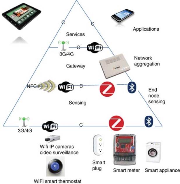
Figure 3.9 Smart connected home and building
Regulation on power dissipation of home-based networking equipment is now common, and for good reason. There is more that can be done. Energy savings made as a result of effective home automation can be enhanced by bundling functionality and services onto a single M2M-enabled digital home gateway which can support IPTV, broadband wireless, media storage and distribution, medical and home automation, and more. A virtualized software platform can allow different service providers or utilities to run concurrently on the same box without interference. Visualization and control can be achieved by connecting via smartphone, TV, tablet, or netbook.
Approach
Table 3.4 shows the software stack for a smart connected home and building.
The Smart Gateway is developed by integrating the OpenWRT for wireless router applications, Live555 NVR for video surveillance, Digital Living Network Alliance (DLNA) server, Asterisk IP-PBX for VoIP (voice-over-Internet protocol), Openfiler for Network Attached Storage (NAS), and ZigBee WSN. These entire open source applications are integrated, optimized, and tested, resulting in a robust turnkey, market-ready solution for a networked Smart Gateway. This reference design also supports Gigabit Ethernet, 802.11n Wi-Fi, ZigBee™, and 3G/4G connectivity simultaneously. The Smart Gateway has built-in security features such as firewall, intrusion prevention system (IPS), IPSec VPN (IP security virtual private network), and content filtering.
Smart Home Automation control is achieved using ZigBee WSN. The ZigBee network standard meets the unique needs of sensors and control devices. ZigBee applications include smart energy gateway applications, home automation through remote monitoring and control of appliances, HVAC control as well as tele-health gateway applications for heart rate monitoring and blood pressure monitoring in addition to security gateway applications with intrusion sensors, motion detectors, glass breakage detectors, smoke detectors, standing water sensors, and sound detectors. ZigBee devices offer low latency and have very low energy consumption resulting in long battery life. As we have integrated the ZigBee mesh network with the TCP/IP stack, with the networked Smart Gateway connected to the cloud, remote monitoring and control anywhere/anytime can be performed with any MID.
In the smart energy gateway application, the design implements the connectivity between ZigBee-enabled smart plugs and the ZigBee coordinator module on the Smart Gateway platform using the ZigBee HA (Home Automation) profile. Appliances which have a built-in ZigBee module can be directly connected to the Smart Gateway platform and the ZigBee-enabled Modlet enables traditional appliances also to communicate with the MPC8308 platform and be remotely monitored or controlled from anywhere at any time. This design enables IoT connectivity and M2M communication.
Table 3.4 Software stack for smart connected home and building
The connectivity between the ZigBee-enabled SE (Smart Energy) meter and built-in ZigBee module on the Smart Gateway platform is implemented using a ZigBee SE profile. In addition, several SE meters can be monitored via a Data Concentrator in the Neighborhood Area Network (NAN). The data concentrator can read the energy consumption data from each of the meters via Power Line Communication (PLC) connectivity and upload the data back to the utility server via 3G broadband. Utility companies can also push messages related to peak-load tariff rate change to each individual home through the smart meters.
Smart secure video surveillance is achieved though WiFi IP cameras supported by Live555 video media server running on the wireless gateway. The gateway also supports DLNA media streaming of videos and music that can be sent to multi-room, multi-users.
Results
· Anywhere, anytime remote monitoring and control of appliances using the Thinkeco smart plug based on ZigBee connected by a ZigBee mesh network hosted by the Smart Gateway using mobile devices through the cloud.
· Full Residential Gateway and infotainment functions
· For example, video surveillance: Remote monitoring, recording and playback of video surveillance @36 Mbps using 12 cameras with D1 (3 Mbps) can be done simultaneously using NVR application. Higher-end multi-core processors can be used to scale the number of cameras to over 100 cameras (video data rate to be over 300 Mbps)
· For example, high performance wireless DLNA media streaming and voice telephony based on high performance wireless access point (AP). An integrated 802.11n Wi-Fi module delivers over 300 Mbps of wireless local area network (WLAN) performance with bandwidth >120 Mbps. With high-end processor, 11ac WiFi can be supported that delivers >900 Mbps wireless throughput.
Conclusion
This Smart Gateway delivers a high-performance, integrated, optimized, and cost-effective solution with multiple applications running simultaneously.
Figure 3.10 shows Smart Connected Home Automation that provides Smart energy, safety, and security. The integration and optimization of multiple open source applications is well tested and validated resulting in a reliable and sustainable reference design solution. It enables remote monitoring and control anywhere, anytime using smart mobile devices for cloud services such as smart energy, Live555 NVR for video surveillance, Universal Plug, and Play (UPnP), DLNA, VoIP, 802.11n Wi-Fi, 3G broadband, and 802.15.4 ZigBee. High performance networking by bridging multiple wireless networks together into a wireless mesh network (ZigBee WSN, TCP/IP, Wi-Fi, and 3G/4G) and high bandwidth wired network (1 Gbps Ethernet) enables multiple gateways for Smart energy, health, security, and residential gateway (ZigBee wireless sensors, Media, and Voice) of cloud application services.
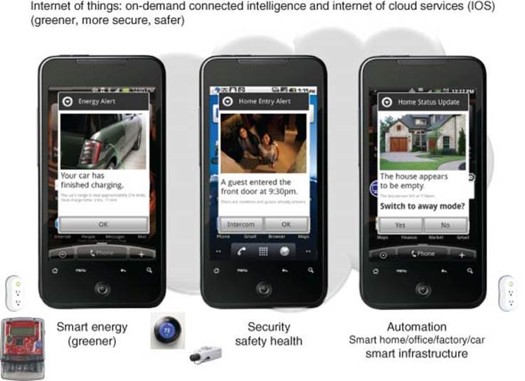
Figure 3.10 Smart connected home automation, smart energy, safety, and security
3.1.3.6 Smart Building Automation
Buildings represent another area where energy efficiencies can be made. In offices, hotels, or campuses, it is reasonable to suggest that people do not have the same motivations as they do at home to conserve energy. The potential for M2M to automate is magnified for buildings because the goal is not only to save energy but also to implement security. CCTV video surveillance and secure access systems such as card swipe, card proximity, or something more advanced like iris scanning, have an increasing role to play in securing our towns and cities (Figure 3.11).
In addition to building automation such as LED lighting, AC temperature, and humidity control, sensors are also deployed for sensing structural issues of buildings and bridges, so that preventive care can be deployed before major collapse happens (Figure 3.12).
New buildings constructed with glass and steel as well as old stone constructions often suffer from poor in-building wireless coverage. A compelling option for in-building M2M networks could be a combination of wireless with wired networking. Daisy-chained Ethernet, for example, can scale the height/length of a building with lower costs compared to the more traditional star or switched network. Wireless can extend network reach across individual rooms or floors.
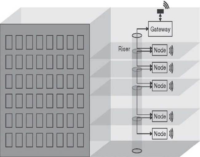
Figure 3.11 M2M network for buildings and factories
3.1.4 Smart Energy and Smart Grid
This section describes Smart Grid applications in all three domains (consumer home, industrial, and infrastructure) as shown in Figure 3.13.
This includes smart meters and smart data concentrators that are used for Advanced Metering Infrastructure (AMI) that also provides the essential Demand Response (DR) for preventing brownouts. Figure 3.14 shows Smart Energy with Smart meter, home area network (HAN), NAN.
Figure 3.16 shows Potential Energy Saving with Smart Energy Management.
3.1.4.1 Introduction
Local networking of electronic devices in houses and buildings offer benefits in a number of areas, ranging from safety and security to energy efficiency and home entertainment features. HANs can be implemented via both wired and wireless solutions, using multiple different standards, and can be remotely controlled and monitored through a gateway to neighbor, wide area, or smart grid networks. Figure 3.15 shows a model of Smart Energy (Smart Grid and Metering) [21]. Table 3.5 shows Software Stacks for Smart Grid and Metering.
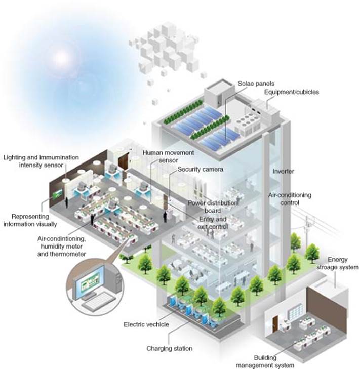
Figure 3.12 M2M industrial automation
While smart grid deployments offer great opportunities for utilities to manage and control energy distribution to their customers, it also gives homeowners the opportunity to better manage their energy usage through smart energy management (Figure 3.16).
3.1.4.2 Home Area Networks (HANs)
A HAN is a dedicated network connecting devices in the home such as displays, load control devices, and ultimately “smart appliances” seamlessly into the overall smart metering system. It also contains turnkey reference designs of systems to monitor and control these networks. Most of our high-energy use today comes from heating/cooling, cooking, lighting, washing, and drying. These home appliances are beginning to become smart with connectivity features that allow them to be automated in order to reap benefits that smart metering and variable tariffs bring. The utility companies are beginning to be able to better manage the energy demand and perform load balancing more efficiently.
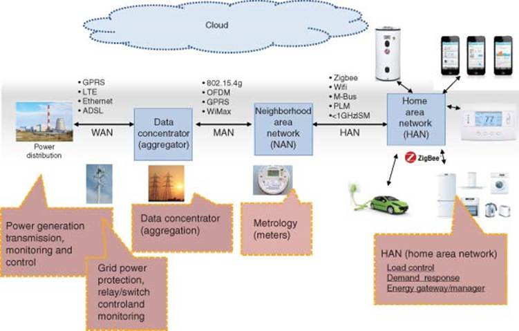
Figure 3.13 Smart grid
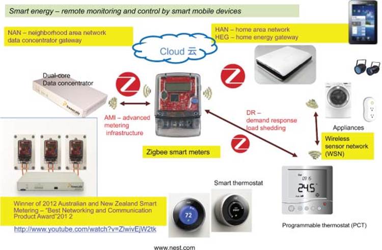
Figure 3.14 Smart grid with smart meter, HAN, and NAN
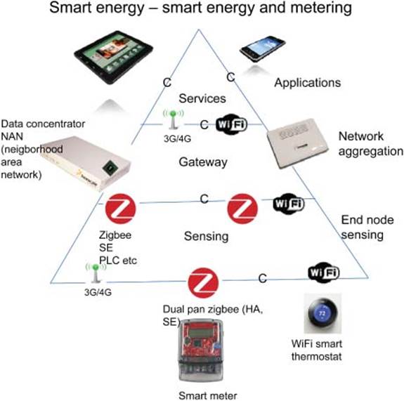
Figure 3.15 Smart energy (smart grid and metering)
Realizing long-term potential savings in a typical home environment through the smart grid means that technology, legislation, and mind-set must come together to drive a permanent change in the way that consumers perceive energy consumption. Figure 3.17 shows a HAN example.
3.1.4.3 Strong HAN Market Growth
According to IMS and Pike Research, the installed base of smart home networks (majority are equipped with home energy management) will increase 4× from 14.7 million homes in 2014 to ~60 million in 2020.
Table 3.5 Software stacks for smart energy
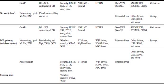
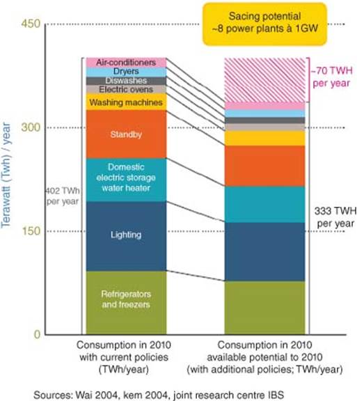
Figure 3.16 Motivation on smart energy management
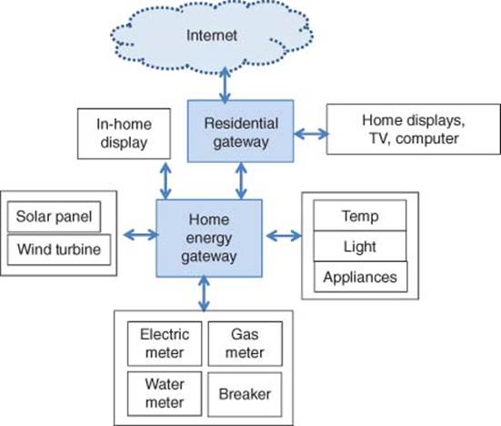
Figure 3.17 Home area network (HAN)
Pike research press release suggests that electric utility companies supports energy efficiency and management and forecasts that the installed base of smart meters will reach 963 million units by 2020 increasingly adopt smart meters.
According to a Pike Research estimate, the number of home energy management users is expected to reach 63 million by 2020.
These numbers indicate that there is a strong growth potential in the HAN market at least for the coming decade, as concerns for using energy efficiently are spreading across the globe.
Some of the key market drivers and influencers for home energy management are
· Growing energy prices. This will result in reduced home energy consumption and encourage smart consumption
· Service Providers. Innovative services around energy management and home security utilities.
· Consumers. Desire for monitoring/controlling remote access to home
· Technology Enablers:
· Commoditization of LAN/WAN networks
· Maturity of low-power technologies (ZigBee, Wi-Fi, Z-Wave, etc.)
· Standardization Bodies. Individual protocol alliances (ZigBee, Z-wave, HomePlug, etc.)
· Application-Oriented Alliances. OpenHAN from UtilityAMI, AHEM, CECED from appliances.
3.1.4.4 Challenges in Implementing HAN
The key challenge in implementing a HAN solution is to connect the entire house/building network to the “external world” for remote monitoring and control, and simultaneously to connect objects inside houses/buildings to offer smart interoperability features (Figure 3.18). A key challenge from the consumer’s perspective is remote controlling and monitoring for surveillance companies, while the challenge from the service provider’s perspective is remote metering for utility companies and security monitoring for surveillance companies.
One such example is connecting PIR sensors to HVAC and lighting systems to turn off heating when windows are open, or turn lights off when no presence is detected.
Summing up, the challenge in implementing a HAN solution is to interconnect different technologies to offer smart services for
· Comfort
· Automation
· Security
· Energy management
· Health.
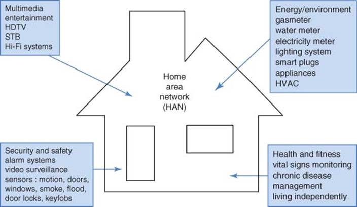
Figure 3.18 Smart networked home forecast
3.1.4.5 Smart Energy Solution
A smart energy solution consists of a HAN with smart appliances and electric meters at one end and grid-end applications such as data concentrator/aggregator, grid routers, and grid power management and protection at the other end (Figure 3.19). The ZigBee smart energy application profile addresses communication from meter to the HAN for purposes of load control and DR. Load control provides the ability for the utility to turn off loads for short periods of time in the customer’s premises during peak loads, while DR is the ability for utilities to communicate with a home the changing utility rates during peak times and similar details. The user will then have an option of taking voluntary action to reduce personal consumption.
3.1.4.6 Smart Energy Gateway
An energy gateway is the interface between the utility-controlled smart grid and energy-consuming in-house objects. Most utility providers prevent direct access to smart meters. The utility providers transmit the smart meter readings to utility servers via the data concentrators. Then, consumers need to connect to the utility server to have access to meter readings. It would be more likely for smart energy gateway to access the main fuse box or the Smart Thermostat.
Figure 3.19 Smart energy solution
3.1.4.7 Data Aggregators/Concentrators in Neighborhood Area Network (NAN)
A data concentrator (Figure 3.20) is an important component in automatic meter reading (AMR) [11].1 More importantly, data concentrators are essential in AMI that provides Demand Response (DR) in load-balance to avoid brownout. It creates the necessary network infrastructure by linking several utility meters (electricity, gas, water, heat) to the central utility server and captures and reports vital data. It also helps synchronize the time and date data of utility meters to a central utility server and enables secure data transfer of user authentication and encryption information. Communication to utility meters is comprised of an RF or wired (power line modem) connection, enabling data transfers to the central utility server via GPRS, Ethernet, and GSM, POTS, or UHF/VHF networks. A data concentrator usually supports the device language message specification (DLMS)/COSEM client/server stack standard to work with multiple meter-vendors.
Figure 3.21 shows a block diagram for an implementation of a data concentrator or aggregator and grid router.
The key functions of the data concentrator are as follows:
· AMI – Energy data collection/aggregation and DR management
· Secure data routing
· Packet time stamping.
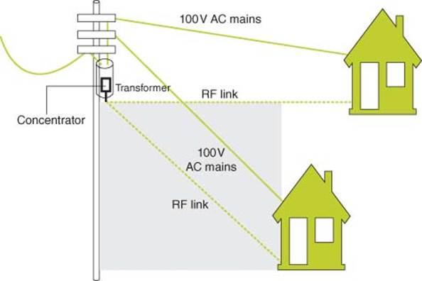
Figure 3.20 Typical data concentrator setup
Figure 3.21 Data concentrator and grid router block diagram
3.1.4.8 Data Concentrator
The data concentrator reference design enables communication to smart grid meters within an NAN. The reference design is capable of a variety of usage models, including smart energy device discovery, communication protocols, and uplink communication to the utility server. The embedded processor used can deliver dual-core performance running up to 533 MHz, enabling a variety of complex usage models within a low power envelope that allows for fanless designs.
The data concentrator will instantly discover and connect with multiple smart energy meters. Enabled with an AMI, the data concentrator allows for bidirectional real-time monitoring and control of multiple meters and transfers real-time information back to the utility server via a 3G uplink. The software protocol supports real-time DR, allowing utilities to communicate with the meters and inject peak-load rate changes to influence load shedding.
In the presence of a smart HAN gateway inside the dwelling, the software can respond to real-time commands or recommendations encouraging smarter energy use, such as powering off EV chargers, washers, dryers, or HVAC systems.
The data concentrator communicates with smart metering devices via the industry standard device language message specification or DLMS (IEC 62056). The widely used protocol consists of a “sign on” sequence, in which the smart meter unit and the data concentrator sign on and negotiate parameters such as maximum frame length (transmission and reception) or security settings. Other protocols of communication between the data concentrator and the utility server are also implemented, including a 3G uplink. RF 900 (sub 1 GHz) and PLC can be supported by the data concentrator.
Other features of the data concentrator include
1. Detection and reporting of line breaks to the utility company
2. Alerting the utility company of smart meter tampering.
The data concentrator includes a complete suite of OpenWRT software that supports the capabilities described above via a simple Web-based UI. The data concentrator is based on a ruggedized, weather-resistant enclosure with internal antennas and power supply.
The features of the data-concentrator (Table 3.6) are as follows:
· Has a high-performance dual-core device with up to 1300 DMIPS
· Discovers and interfaces to smart metering devices and implements DLMS protocol to standardize communication
· Collects, analyses, and transfers energy data to the utility server
· Detects broken links and tampering events
· Has broadcast capability to the utility server using a 3G uplink card.
3.1.4.9 Grid Router
The grid router’s main function (Figure 3.22) is to provide secured connectivity interface between the smart meter and the utility network, performed using a grid router (sometimes referred to as a concentrator). The role of the router is to provide a link from the utility company to all local smart meters, usually running a real-time operating system and provide high-level services such as communications stacks, message prioritization, store/forwarding, network routing, and discovery.
Table 3.6 Data concentrator features
|
Processor |
Processor 667 MHz dual core device |
|
Connectivity |
Serial line drivers for communication to power line communication controllers |
|
Memory |
Up to 128 MB of NOR/NAND flash memory |
|
Enclosure and design |
Energy efficient passive cooled design, natural convection capable Ruggedized, weather resistant construction |
|
Future development |
Power line communication (PLC) and sub-gigahertz RF interfacing and protocol development |
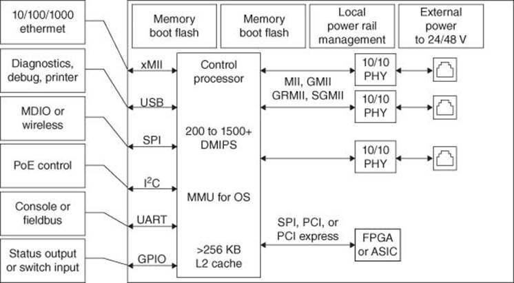
Figure 3.22 Grid router block diagram
Below are some of the key features that distinguish grid router solution:
· High performance (100 up to 38 000 MIPs)
· Built-in security functions supporting public and private key cryptography
· Wide range of communication ports, including Gigabit Ethernet and fast serial ports, plus USB 2.0 for local on-board interfacing
· Secured Connectivity.
3.1.4.10 Secured Connectivity
Depending on local needs, various options for wireless communication include short range wireless (sub-gigahertz) through 2.4 GHz ZigBee alliance and PLC (low frequency carriers typically below 500 kHz) using power line modem solutions for local communications and options from longer range communications such as ZigBee, Wi-Fi, Ethernet, ISDN, HDMI, PLC, Bluetooth/BLE, RF4CE, HomePlug, Z-Wave, and GPRS through strong alliance with leading smart grid standards bodies and committees.
3.1.4.11 ZigBee and Smart Energy
ZigBee (Figure 3.23) is a low-power wireless communications technology designed for monitoring and control of devices. Based on IEEE 802.15.4 standard, ZigBee technology provides a robust and reliable solution in noisy radio frequency (RF) environments. ZigBee features include energy detection, multiple levels of security, clear channel assessment, and the ability to cover large areas with routers and channel agility. These features help devices pick the best possible channel and avoid other wireless networks such as Wi-Fi, while the message acknowledgement feature ensures that the data was delivered to its destination. There are also software defined radios (SDRs) operating in sub-gigahertz range (adjustable from 315 to 960 MHz) such as the ZigBee wireless transceiver. Today, the WMBUS stack is supported on this device by one provider, built, tested, compatible, and ready for integration.
Figure 3.23 ZigBee® and smart energy
3.1.4.12 Security
With so many forms of communication, security of these communications and that of the grid is paramount. The embedded processor selected should support an expansive range of security protocols and functions for both private and public key cryptography to help ensure that these links are protected from external attacks. For low data rate communication, AES and DES are commonly used. Since these are private key cryptography functions, extra care is needed to help ensure system integrity. The processor should also provide secure on-board storage of the keys to provide enhanced security for local communication.
3.1.4.13 Grid Power Management and Protection
Electricity substations are under increasing pressure to provide functionality to actively manage the local grid. Deployment of new, high performance power controller systems is now common across all regions as utility companies attempt to stay one step ahead of the technical challenges they face. Power relay controllers must manage surges and loading on the grid locally. Real-time control is essential to maintain grid integrity.
This is accomplished using embedded processors that support the IEEE 1588 protocol. A move toward cost-effective functional integration brings the focus toward multicore MPUs. Today, dual core is adequate for providing a cost-effective, comprehensive range of fast serial communications and dual-core performance.
Adding power meter functions in the power breaker provides more information on grid performance and loading. MPUs run SCADA for substation control and must have fast response times for the management of transient events (such as surges).
3.1.4.14 Power Efficiency
Low power operation is also an important consideration for MPU choice. Fanless operation greatly improves overall system reliability as these units may be installed in remote substations and they have a long maintenance cycle. Power Architecture products are highly efficient and many are designed for fanless operation, delivering gigahertz class performance at below 3 W.
3.1.4.15 Conclusion
The need for more efficient use of energy has led to the growth of the smart grid. Companies and government are enabling this management through the deployment of devices designed to efficiently manage power in the home and on the grid network.
3.1.5 Smart Energy Gateways
At the most basic level, there are two primary initiatives underlying the smart grid: generating clean, sustainable power and intelligently managing the distribution and use of that power. Achieving the transition to clean power generation will take many years, with an accompanying investment of billions of dollars. On the other hand, the means to intelligently manage the distribution of power and reduce how much each of us consumes is not only possible today, it is essential if we need to satisfy the escalating global demand for energy until new, clean, power generation sources come online. In order for utility companies to intelligently balance and distribute power, they need the ability to see where, how much, and when energy is being consumed. To create this ability, a fundamental feature of the smart grid is enabling the power distribution network to support the bidirectional flow of both power and communication capabilities from power distribution facilities to consumption locations. In more detail, this two-way communication extends from distribution centers out to urban clusters or neighborhoods and then branches out to individual residences and businesses which are connected to the smart grid by their electric meters, and increasingly, to individual devices within the premises itself. This network grid is illustrated in Figure 3.19. Just as individual computers, printers, storage systems, and servers are connected over Ethernet or wireless Ethernet (Wi-Fi) networks, the smart grid will connect devices that transmit, monitor, and consume electricity using a variety of new smart grid networking standards, including PLC, M-Bus, ZigBee technology, and Smart Energy 1.0 [12].
The smart grid device that enables utility companies to capture customer usage data is the smart meter, represented in Figure 3.24 by the metrology symbol in the middle of the diagram. The evolution of smart meters has been incremental, beginning with the integration of short-range RF technologies that allowed “drive-by” capture of meter readings, which saved time and improved accuracy. Next has followed smart meter improvements that have completely eliminated the need for mobile field staff to capture meter data. This latest round of smart meter improvements has been based on standards-based communication technologies driven by the AMI organization. The use of standards-based communication technologies has opened the door for existing home networking platforms, such as residential gateways and broadband AP routers, to incorporate support for them as well. This new class of platform is referred to as a “smart energy gateway,” or alternatively, a “home energy gateway,” and represents the heart of the HAN.
The key modifications necessary to enable a residential gateway to serve as a smart energy gateway is support for the physical layers (PHYs) and protocols that have been adopted for use in smart meters for communication. The PHYs used in smart meters include PLC, ZigBee, and 802.11. The associated communication protocols include DLMS, Smart Energy 1.0, and M-Bus in the European market. The integration of these PHYs, together with support for the communication protocols associated with them, are key requirements for designing a smart energy gateway. Increasingly, these same PHY technologies are rapidly being adopted for use within the HAN to support home automation connectivity with appliances, lighting, security systems, and health monitoring devices, as illustrated in Figure 3.25. Both the AMI organization as well as the Association of Home Appliance Manufacturers (AHAM) is guiding this enablement. Other considerations that must be factored into smart energy gateway designs include support for WAN access, and perhaps most importantly, a UI that enables access, monitoring, and control over the connected HAN devices.
Figure 3.24 Home area network
This last factor deserves special emphasis. The ability to access, monitor, and control devices within the HAN is an essential capability if consumers are going to successfully manage and conserve the energy they use. The UI must allow customers to see exactly how much energy they are using, how much the utility company is charging for that energy, and provide the ability to exercise control over HAN-connected devices if necessary. Of equal importance to providing this UI is the ability to access it remotely, at any time, via a smart handheld device or tablet. This capability leverages the global preference by consumers to utilize a single smart device for all their communication applications, extending from voice, texting, email, and entertainment, to now include home monitoring, security, and control.
One example of these efforts is a networked Smart Energy Gateway (nSEG) reference design, shown in Figure 3.25. This multifunctional gateway can support M2M connectivity from smart handheld devices, such as smartphones or tablets, to the HAN.
Figure 3.25 Smart energy gateway block diagram
Through this M2M connection, a user can remotely monitor energy usage, receive alerts from their utility company regarding billing or tariff changes, and manage the smart devices within their HAN.
The smart gateway enables connectivity between a variety of ZigBee-enabled HAN devices (with provision for powerline modem support) allowing them to be accessed and controlled over an M2M link from any smart handheld device via its GUI, as shown inFigure 3.26. In addition, the nSEG supports the latest 3 × 3 802.11n Wi-Fi radio modules via its PCI Express port, together with high performance gigabit Ethernet to enable true broadband connectivity. For wireless broadband applications, the 3G or 4G USB module, are supported via the two high-speed USB2.0 ports. The nSEG reference design kit includes a comprehensive suite of license-free OSGI software, including gateway, NVR, NAS, and DLMS stacks.
The low power home energy gateway reference platform features are as follows:
· A powerful, low power consumption applications processor that integrates a power management unit, a cryptography unit, and a rich set of connectivity controllers
· Dual ZigBee radios (with provision for power line modem) to enable seamless, plug and play connectivity to smart meters and the HAN automation system
· A WLAN wireless radio or Ethernet wire line interface (with provision for 3G/GPRS modem) to enable secure end-to-end HAN control and monitoring, either online or remotely, through a broadband access to the Internet
· A display interface to enable household management through an engaging and intuitive user interface.
Figure 3.26 Graphical user interface to interact with smart gateway
3.1.5.1 Overview of Smart Gateways for Energy Management
Governments worldwide are mandating improved energy efficiency, requiring an investment in the new smart grid and smart energy management structure. The goal is to create a smart grid that will change the way power is deployed for sustainable energy around the world. At the heart of the worldwide rollout of smart meters and the construction of a smart grid network infrastructure lies the goal of energy efficiency from the generation, transmission, and distribution to the end customer. Leveraging the deployment of communications-enabled electricity meters, many applications can be offered to homeowners for optimizing overall energy management and to utility companies as a means of managing the load of their grid and preventing power demand peaks. Energy gateways are the interface between the utility-controlled smart grid and energy consuming in-house objects.
3.1.5.2 Networked Smart Gateways (NSG)
The smart grid device that enables utility companies to capture customer usage data is the smart meter, as a part of the HAN on the left side of the diagram (Figure 3.27) [13].2 The evolution of smart meters has been incremental, beginning with the integration of short-range RF technologies that allowed “drive-by” capture of meter readings, which saved time and improved accuracy. Next, smart meter improvements followed that eliminated the need for a mobile field staff to capture meter data. This latest round of smart meter improvements has been based on standards-based communication technologies driven by the AMI organization. The use of standards-based communication technologies has opened the door for existing home networking platforms, such as residential gateways and broadband AP routers, to incorporate connectivity support. This new class of platform is referred to as a “smart energy gateway,” or alternatively, a “networked smart gateway (NSG)” and represents the heart of the HAN.
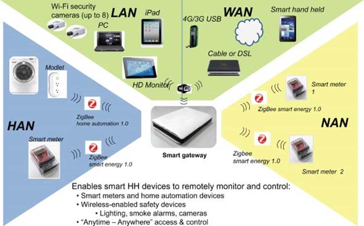
Figure 3.27 Networked smart gateways multiple services
3.1.5.3 Key Benefits of Smart Energy Gateway or NSG
A smart energy gateway provides the necessary interface between the utility-controlled smart grid and energy consuming in-house object. The following are some key benefits:
· Control activation/deactivation of HAN appliances
· Collect real-time energy consumption from smart meter and power consumption data from various in-house objects
· Generate dashboards to provide feedback about power usage
· Provide control menus to control appliances
· Connect to cloud; WAN for remote monitoring and control.
3.1.5.4 Challenges in Implementing Smart Energy Gateway
The key modifications necessary to enable a residential gateway to serve as a smart energy gateway is support for the PHYs and protocols that have been adopted for use in smart meters and home automation devices. The PHYs used in smart meters include: HomePlug Green PHY (Power Line Communication), ZigBee technology, and 802.11. The associated communication protocols include DLMS, Smart Energy 1.0, Smart Energy 2.0, and M-Bus in the European market. The integration of these PHYs together with support for communication protocols associated with them is a key requirement for designing a smart energy gateway. In parallel, these same PHY technologies are rapidly being adopted for use within the HAN to support home automation connectivity with appliances, lighting, security systems, and health monitoring devices, as illustrated in Figure 3.27. AMI as well as the AHAM, the USNAP consortium, and HEMS Alliance, are guiding this enablement. Other considerations that must be factored into smart energy gateway designs include backhaul support to WAN, and perhaps most importantly, a UI that enables access, monitoring, and control over the connected HAN devices.
This last factor deserves special emphasis. The ability to access, monitor, and control devices within the HAN is an essential capability if consumers are going to successfully manage and conserve the energy they use. The UI must allow customers to see exactly how much energy they are using, how much the utility company is charging for that energy, and provide the ability to exercise control over HAN-connected devices, if necessary.
Of equal importance to providing this UI is the ability to access it remotely, at any time, via a smart handheld device or tablet. This capability leverages the global preference by consumers to utilize a single smart device for all their communication applications, extending from voice, texting, email, and entertainment to now include home monitoring, security, and control.
3.1.5.5 Smart Energy Gateway
The smart energy gateway solution (Figure 3.25) is designed to address the challenges mentioned above. This multifunctional energy gateway can support M2M connectivity from smart handheld devices, such as smartphones, or tablets, to HAN. Through this M2M connection, a user can remotely monitor energy usage, receive alerts from their utility company regarding billing or tariff changes, and manage the smart devices within his/her HAN. Due to this, it serves as a single-chip solution providing all necessary secure connections between end-to-end devices in smart grid network.
3.1.5.6 Smart Energy Gateway Functionalities
The smart energy gateway (Figure 3.27) with integrated ZigBee module enables connectivity with any ZigBee-enabled HAN device. This allows the HAN to be accessed and controlled over an M2M link between a smart handheld device and NSG, using an intuitive GUI. The smart energy gateway supports HAN, WLAN, and WAN connectivity, with an integrated MPC13226 ZigBee radio for HAN connectivity to smart meters as well as smart plugs and appliances, an integrated 802.11n Wi-Fi module that delivers 300 Mbps of WLAN performance and support for broadband WAN connectivity via either cable, DSL, or LTE/3G. In addition, NSG also supports the latest 802.11n Wi-Fi radio modules via its miniPCI connector, as well as dual Gigabit Ethernet ports, to enable true broadband connectivity.
For wireless Internet connectivity, a 3G or 4G USB module can be attached via either of the two high-speed USB 2.0 ports that are provided on the NSG.
The smart energy gateway reference design kit includes a complete suite of Open- WRT software that requires no license fees and supports the following applications: GUI that enables Web-based access and management of connected devices and applications, NVR for home surveillance, HD video streaming, and ZigBee HAN profiles for Smart Energy 1.0 and Home Automation 1.0.
3.1.5.7 Key Features of Smart Gateway
· Seamless wireless connectivity (TCP/IP, 802.11n, ZigBee). Smart metering via ZigBee sensors (via SE 1.0 or MBus)
· Remote management and control of smart appliances (via ZigBee HA1.0)
· M2M “anytime/anywhere” access and management, via smart handheld or Web-enabled devices
· Simple Web-GUI. Easy to use with any Web-enabled device; meter reading, energy consumption, and history alert notifications of tariff changes by utilities in real time
· DR: Manage energy usage (HVAC, lighting, car charging, etc.)
· Home automation and security
· Integration of four essential software stacks.
· TCP/IP: Broadband WAN/LAN connectivity
· ZigBee Home Automation 1.0 Profile
· ZigBee Smart Energy 1.0 Profile
· Dual-PAN radio that supports both HA1.0 and SE2.0 simultaneously on one ZigBee radio
· Web-based GUI (Java)
· Cost-optimized bill of materials
· Enables “anytime/anywhere” access and control over an M2M link from any smart handheld device via its GUI
· Provides a superb price/performance blend and the horsepower to run a variety of applications simultaneously
· Supports a rich mix of networking capabilities such as VoIP; HD video streaming, home security, and surveillance; and energy management, and home automation control
· CE and FCC Class A certified, RoHS compliant, ready for mass production
· Complete OpenWRT software suite.
3.1.5.8 Summary on HAN (Home Area Network) Smart Gateway
Bridging the smart grid with the HAN, the networked smart gateway solution delivers new possibilities in home energy monitoring, while allowing utility companies to tailor specific energy packages. The multi-application versatility and cost-effectiveness of the networked smart gateway makes it an ideal solution for adding home energy management and control capabilities to a standard broadband gateway platform.
Smart Home Gateway allows one to remote control appliances using mobile smartphones and tablets. This will empower consumers, help them change their behavior, and reduce their bill.
In addition, a large increase in electricity demand is expected in the coming years, as traditional energy electricity is replacing other sources; this is especially true for cars, where electric vehicles are considered a more environmental friendly solution for the future.
To be able to accommodate all these anticipated changes, the electricity grid needs to transition from a hierarchical, unidirectional, and centralized grid to a distributed and networked grid accepting injections of power generated by consumers using renewable energy resources.
To ensure power availability and power efficiency, and to avoid power grid instabilities resulting from bidirectional power flows and less predictable demand, integrated information and communication technologies (ICT) network acting as a control plane is also required.
The bidirectional, decentralized, electricity grid, and its associated ICT control plane are at the heart of the smart grid, but will however only be able to maximize its benefits if communication to the home and among appliances within the home can be ensured.
The promises of the smart grid can therefore come to fruition only if greater response, greater engagement, and active participation from end consumers within homes can be ensured.
Active consumer participation in DR program will enable users to contribute to grid flexibility and resilience, and enable users to adjust their electricity demand (and thus their bill) as a response to price signals or reliability-based actions.
Greater engagement in distributed energy resources will offer consumers an unprecedented array of choices in how to use, store, or sell their energy in line with their economic and social values.
The above-mentioned smart energy services and applications, enabled by the smart electricity grid will however not be hosted on the smart meter, the grid’s endpoint into residential homes, but will need to be hosted on complementary devices like the home energy management box. This modular device will help provide comprehensive management of energy within customer premises.
3.1.5.9 Home Energy Management Gateway (HEM)
Most consumers only have a vague idea of the amount of energy they use for different purposes [14]. They are however very much concerned about their energy bill and are willing to save money, behave “greener,” and save energy, provided they understand where the electricity goes, how much they waste, and provided they understand how they can derive tangible benefits from an optimized consumption.
It is therefore important for consumers to be able to track energy costs in real time, and to be able to understand the various energy flows within the home or building.
The smart meter makes it possible for consumers to save on their energy bill, but does not do that by itself; smart meters mainly help utility companies get better readings on electricity use and help utility companies save energy and money.
To help consumers do the same, while at the same time making sure that the utilities’ expectations regarding consumer adoption rate in DR or load management programs are met, it appears that besides smart meters, rollout of consumer-friendly companion devices within homes is mandatory.
The home energy management gateway connected to a multitude of devices within the home, ranging from smart meter, smart washing machine, remote controllable HVAC, to PHEV charging station, is one such consumer-friendly device. It can host automatic DR programs reacting to utility messages according to user-set policies, but also host nonintrusive load disaggregation software making the end users aware of their real time energy consumption pattern and behavior.
The 24/7 always-on gateway can help solve the problem of premises energy management and either act as an energy coach or take a more active role and act as a dynamic load shifting controller. The energy coach can propose energy saving tips aimed at reducing the overall energy profile, and the load shift controller can silently manage one’s home or small business energy usage, and sequence nonsimultaneous activation of controllable devices to low energy cost times, on an hour-by-hour or even minute-by-minute basis.
In the future, the gateway could also act as an energy manager coordinating energy flows within premises: according to real-time time-of-use electricity rates, local generation capabilities and local electricity storage levels, the box could balance the user’s comfort level and lifestyle with a minimized utility bill and optimize local energy use/store/sell decisions.
A typical deployment scenario for the Home Energy Management Gateway within the home is shown in Figure 3.27.
The Home Energy Management Gateway receives price events or demand–response events through the AMI network and its smart meter interface to the home (or potentially through the broadband interface).
· Monitors and controls a set of demand–response-enabled appliances (e.g., thermostat, water boiler, and heater)
· Monitors and controls a set of home-automation-enabled appliances (e.g., washing machine and dimming lights)
· Reads power figures out of the various meters and loads on a periodic basis
· Serves rich analytics (e.g., load disaggregation results) to various online, mobile, or local displays, and is ready to
· Runs certified third-party value-add widgets (e.g., energy saving widgets)
· Monitors microgeneration unit production
· Monitors electric vehicle charging
· Sequences controllable loads, so they do not run simultaneously or sequences soft-start gradual recovery mechanisms after power outage helps optimize both electrical power generation and transmission losses as lower current needs will also result in lower quadratic-dependent wire losses.
3.1.5.10 Home Energy Management Development Platform
The Home Energy Management reference platform has been developed [8] as an open hardware and software development platform aimed at jumpstarting design of new products complementing the smart meter rollout.
The platform can serve as the basis for devices targeting consumers willing to manage and control, in real time, consumption of electricity and other energy loads in a building or a house.
The platform comes with prevalidated technologies enabling household or building occupants to remote control or program an array of automated devices, to manage energy usage in an intelligent way, and to interconnect with the different technologies in the home.
Targeted first for energy management, time of use, or DR-ready devices, the platform has been envisaged such that upcoming requirements for deployment of value-added applications (such as customer-specific tips and hints for optimizing energy consumption, utility incentives), detection/prediction of appliance and equipment failures, video surveillance, monitoring of microgeneration units or distributed storage, or electric vehicle charging, can easily be addressed in the future.
The platform is powerful enough not only to collect real-time data delivered by a network of intelligent meters and sensors but also to run a framework processing and delivering analytical visualizations in an intuitive and powerful visual way through a number of access methods such as touch screens, mobile phones, and web browsers.
As such, the platform provides a solid foundation for the development of feature-rich and easy to install HAN appliances supporting exciting ways of engaging, educating, motivating, and empowering individuals to conserve resources and save money.
Optimized to address today’s market needs, the Home Energy Management development platform is modular and designed with the future in mind by accommodating for upcoming and foreseeable requirements such as monitoring microgeneration units or electrical vehicle charging. Extension ports and connectors, for example, power-line modems, RS-485-based solar inverters, and additional communication modules are also available on the platform.
Additional value-added software, in the form of an OSGi framework or a home automation framework, is available from ecosystem partners and enables customers to further reduce their overall design cycle and their overall time to market.
3.1.6 Industrial and Factory Automation
Much of our transport, civic, and industrial infrastructure (e.g., road, rail, tunnels, bridges, waterways, and pipelines) asset base is still monitored and maintained using very labor-intensive processes. M2M technology has real potential to provide more cost-effective autonomous techniques to help with remote monitoring and preventive maintenance. While their needs often differ, they face one common problem: the cost involved in cleanup operations and insurance payouts after subsidence, landslip, or breached canal embankments is usually huge. While open spaces lend themselves well to using wireless technologies, it is not uncommon to find fiber laid along the lengths of rail-track, roadways, and so on, that could form part of the solution infrastructure (see Figure 3.28). Key selection criteria for the appropriate embedded processors include connectivity, storage, and packet processing, in order to support M2M gateways in infrastructure. Figure 3.29 shows the industrial IoT connectivity model for Smart industrial, building, and factory automation as well as for retail and Point of Sale (POS) and ATM kiosks. Table 3.7 shows the software stacks for the industrial IoT.
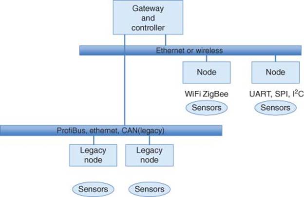
Figure 3.28 M2M industrial infrastructure
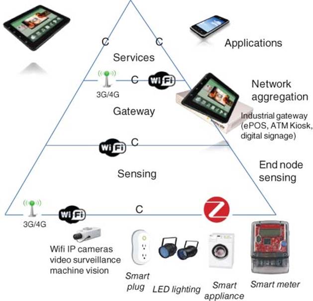
Figure 3.29 Smart industrial, factory/building automation, retail, and POS/ATM
3.1.6.1 M2M for Smart Manufacturing, Smart Factories
Smart manufacturing includes factory automation such as automated assembly and packaging using robotics, machine vision, and machine learning. Smart industrial gateways are used to connect legacy machines with numerous legacy connectivity platforms such as CAN bus, Ethercat, and Profibus. Programmable Logic Controllers are used in SCADA network of this industrial equipment [15].
3.1.6.2 M2M for Smart Retail
Smart retails include deployment of ePoS, ATMs, kiosks, smart vending machines at shops and hospitalities. Deployment of digital signage and self-service kiosks and checkouts is growing rapidly. The addition of sensors and short-range wireless to digital signs has turned them from screens into interactive displays, providing stimulus for advertisers who can now target and connect with new customers. NFC technology allows users to interact with advertisements via their smartphones.
Table 3.7 Software stacks for smart industrial, factory/building automation, retail, and POS
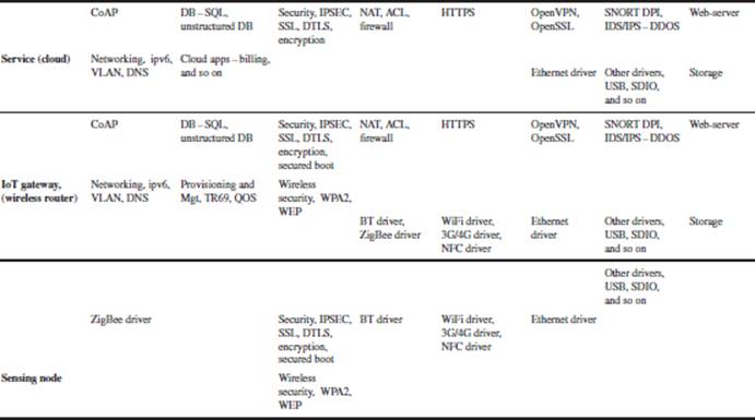
Context-aware and location-based services (LBS) IoT leverages sensor technology can be used to identify context and demographics (who, where, when and in the future, the mood) of passersby and deliver context-aware services accordingly. Owing to its connectivity and high-performance features, general-purpose applications can be added, such as digital signage capabilities.
3.1.6.3 Summary on Smart Industrial (Grid/Energy, Buildings, Factories, Retail)
While the particulars of each use case may vary, the rationale for using M2M is consistent: safety, security, power, and cost savings.
The potent combination of advanced packet processing, energy management, and integrated I/O flexibility with trusted boot will allow developers and integrators to quickly deploy wired and wireless M2M systems they can trust. When considering the volume of M2M nodes and gateways which will be deployed, often in reasonably accessible places, trust and security are vital.
3.1.7 Smart Transportation and Fleet Logistics (Connected Cars – V2X: V2V, V2I)
Smart transportation applies to smart car, smart bus, smart train, and so on. The automobile industry already has implemented some M2M in the past. An example is the TPM (tire-pressure-monitor), which has a pressure sensor integrated with an MCU that detects tire pressure at each tire and transmits the reading to the instrument panel also known as DIS (Driver Information System). The DIS also has numerous operational sensor information of the car such as speed (odometer), RPM reading, motor, and transmission oil level, water, and coolant fluid level, GPS location, brake pad wearing, which are connected to the OBD II (On board Diagnostic) connector underneath the steering column as well as the display on the instrument panel. After-market products can be purchased that take the information from the OBD II connector and send it to a smartphone in the car, which can then send the same to the cloud (Internet). One use-case of this is that insurance companies can allow drivers to select an option where their driving habits can be monitored remotely and the insurance companies can provide a discount to drivers with good driving habits.
The car’s OnStar device detects a crash (air bag deployed) and automatically sends the GPS location and owner’s information to an emergency response center which dispatches 911 assistance.
Many cars already are equipped with ADAS (Advanced Driver Assistance System) such as active braking and active speed control that detect your car is approaching too close to another object, then decelerate the car by apply braking, lane change warning that detects your car has drifted away from your lane, blindspot detection detects objects in your blindspot, and so on.
Smart transportation is tracking of vehicles such as truck and taxis with GPS tracking connected to the cloud so that real-time fleet logistics and scheduling can be performed.
Additional OBD II data such as speed can also be transmitted to the cloud in real time so that the trucking and taxi companies can monitor their drivers to ensure safe driving practices.
Figure 3.30 shows the IoT connectivity model for Smart Transportation and Table 3.8 shows the software stack for Smart Transportation.
An emerging inter-car communication application being developed is the smart connected cars with V2X (Figures 3.31 and 3.32) for active safety and accident avoidance. Information on vehicle-to-vehicle (V2V) communication and vehicle-to-infrastructure communication (V2I) can be accessed from http://www.Dot.gov. In the next few years, each new car equipped with V2V will have a wireless smart gateway that transmits an 802.11p WiFi DSRC (Digital Short Range) beacon consisting of GPS location, speed, and direction of travel while receiving beacons from other cars in the vicinity. The smart gateway in your car will compute in real time with low latency to warn you that you will have a collision in 10 s if you continue on the same path at the same speed. Your onboard smart gateway can also trigger active speed control and active braking to take action as well as relating collision and traffic jam messages to the cars behind you once your car receives a collision notification from the car in front. With inter-car communication, accident messages can be deployed in real time to cars behind, and your car can also take action to reroute in order to avoid the traffic jam and collision ahead.
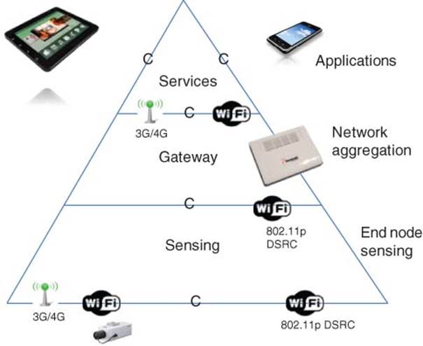
Figure 3.30 Connected smart transportation, smart car – V2X (V2V, V2I)
Table 3.8 Software stacks for connected smart transportation
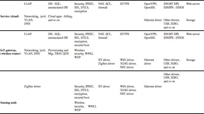
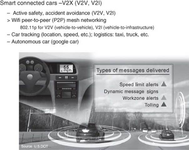
Figure 3.31 Smart connected cars
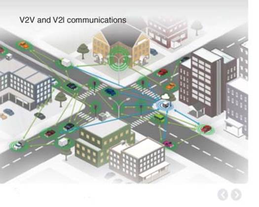
Figure 3.32 V2X (V2V and V2I)
V2I application allows your on-board smart gateway sensors to communicate with the road infrastructure such as traffic lights and speed signs. If your car is following a truck or in a fog, you will be alerted if you attempt to drive through a red light when it is changing from green to red. Likewise, you will be alerted if you are driving over the speed limit posted by the speed limit sign and conceptually, once this road infrastructure is cloud connected, a ticket can also be issued to you and charged to your RFID tag automatically as well.
In V2X, data received can also be traffic information such as congestion, accident, service reminders, targeted marketing, and sales information. Data transmitted by V2X can be vehicle health data regarding engine, transmission, emission (such as OBD II), driver performance data, anti-theft information, telematics data such as GPS location.
3.1.7.1 Smart Transportation (Car, Bus, Train, etc.) Vehicle Telematics
OBD II information is commonly used by vehicle telematics devices that perform fleet tracking, monitor fuel efficiency, and prevent unsafe driving, as well as for remote diagnostics and by pay-as-you-drive insurance. Although originally not intended for the above purposes, commonly supported OBD II data such as Vehicle Speed, RPM, and Fuel Level allow GPS-based fleet tracking devices to monitor vehicle idling times, speeding, and over-revving. By monitoring OBD II DTCs, a company can know immediately if one of its vehicles has an engine problem and by interpreting the code and the nature of the problem. OBD II is also monitored to block mobile phones when driving and to record trip data for insurance purposes.
Ultimately, semi-autonomous and autonomous car with and without the driver will soon arrive.
3.1.7.2 Smart Traffic – Smart Roads, Highways, Road Infrastructure
Sensors can also be installed on roads and highways to provide guidance to the drivers such as speeding, crossing stop signs, and red lights. Sensors can be used to track traffic flow so that dynamic traffic light control can be implemented to optimize traffic flow to minimize traffic jams, resulting in fuel saving and reducing carbon emission that causes air pollution.
3.1.8 Smart City
Smart City infrastructure deploys street lighting control and video surveillance for public security, safety as well as parking meters, smart road/traffic, emergency response, and so on (Figure 3.33).
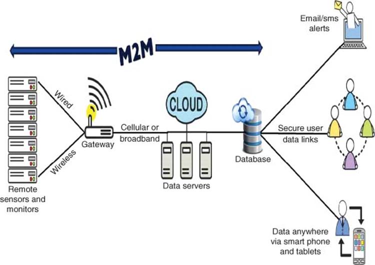
Figure 3.33 Smart environment in smart city
In addition, Smart City maintains smart environment by deploying sensors to monitor air and water quality, energy, waste, noise and road/traffic monitoring such as from Envirologger http://www.envirologger.com/.
In addition to building automation such as LED lighting, AC temperature, humidity control, sensors are also deployed for sensing structural issues of buildings and bridges, so that preventive care can be deployed before a major collapse happens.
In addition to smart street lights, video surveillance cameras are added for public safety and security, as well as smart traffic monitors of vehicles and pedestrian traffic and optimizes the flow of vehicles and pedestrian routes. Smart parking meters notify drivers on available parking spots. Smart transportation systems include smart roads and highways with warning messages for weather, accidents, and traffic jams.
3.2 Smart IoT Platform
This section presents the use of Smart IoT Platforms to deploy IoT products, systems, and solutions. There are 7S’s success criteria for IoT Systems: the top 4S’s of IoT success criteria are Simplicity, Secured, Smart software, and Scalable.
· Simplicity. Easy to use, install and reset, Easy on the Eyes, Simple Solution to Complex Problems
· Security. Privacy, protection from intrusion
· Safety. Safety, stability, supportable
· Smart. Adaptive, Analyze, Action, Anticipate (Location/Context Aware, Predict), Autonomous
· Scalable service (HW and SW) and Standards (open-standards). Easily scalable by various types and number of end nodes and users (interoperate with other devices); as well as data rate
· Sustainable, Performance, and Power efficient. Long battery life, power saving modes, energy harvesting
· Sleek Appeal and Aesthetic. Good Look and Feel (Attractive) to match Smart Living, Smart Environment, and Community.
The following sections expand on two of these important success criteria – Smart and Secure IoT software platform.
3.2.1 Smart IoT Software Gateway Platform
This section expands on the “Smart” IoT systems that will prove an important success factor for mass IoT adoption [3, 5].
https://community.freescale.com/community/the-embedded-beat/blog/2014/07/16/smart-IoT-systems--the-missing-s
Smart IoT system solutions are based on “Smart” software platforms (Figures 3.34 and 3.35, Table 3.9) characterized by 7A’s. The top 4A’s are awareness of context, analyze and take action, anticipate, automate, and autonomous.
· Awareness of Context and Location. Smart IoT system solutions are customizable by context and location. Smart software behaves differently according to who, when, where, and so on. The rule-based abstraction provides additional simplification and ease of use.
· Analyze and Take Action. Smart IoT systems have balanced local storage that allows analysis, local processing, and data/event filtering at the sensor node and gateway level, as well as making localized decisions and taking actions at the cloud level. This enables faster response and lower latency rather than always going to the global cloud for action, which in turn results in more intelligent, selective transmission of sensor data so as not flood the cloud with Big Data.
· Anticipate, Predict. Smart software understands the user and knows their usage history. It then anticipates, making relevant predictions based on context and use history. This can help deliver targeted sales and marketing solutions and services. VO
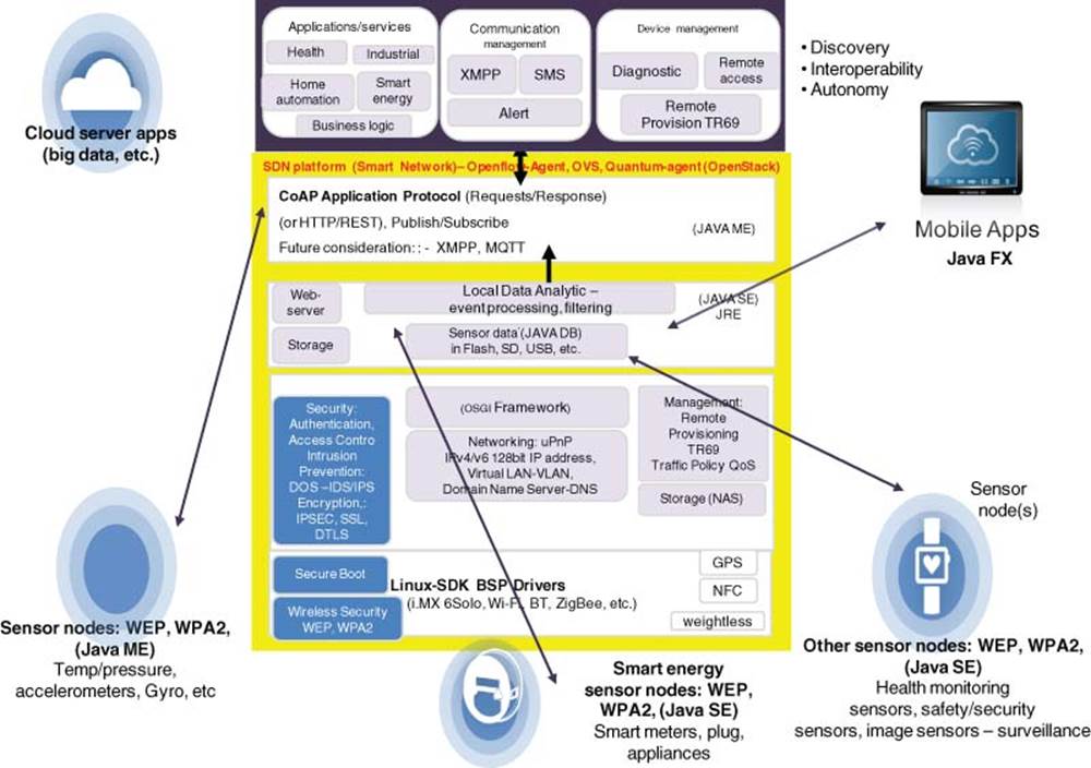
Figure 3.34 Smart, secured IoT software platform <image/>
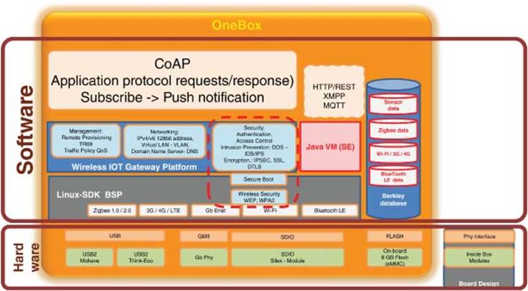
Figure 3.35 IoT software platform architecture
· Automate. Apply simple solutions to complex problems. Smart IoT products will improve efficiency by automating and streamlining processes through automated monitoring and control.
· Autonomous. A truly smart system independently makes informed decisions and takes appropriate actions with a self-governing, self-organizing ability. Autonomous systems are usually rule based with a knowledge-based reasoning ability. Smart devices can “discover” each other and can interoperate (collaborate) together. In addition, future smart devices and smart gateways will be connected through the Software-Defined Network (SDN). This facilitates the entire end-to-end network to be visible and manageable as an adaptive smart system, so high availability such as auto-failover and load balancing can happen dynamically to shift traffic load from one equipment to another.
· Automated Remote Provisioning and Management. Typically, this is cloud based, from initial installation and configuration to management. The ability to support remote monitoring, tracking, management, and control is critical. Smart sensor devices and smart gateways can and must be remotely managed, serviced, and sustained.
· Augmented Reality. This can take many forms, including easy-to-use HMI, gesture user interface, voice in/voice out with natural language analysis/interpretation, and data/knowledge mining. Adaptivity is also important. Products with learning mode and dynamic, on-demand real-time rule-based adjustment.
· Aesthetic. Sensory attraction is important too. Smart products must have a pleasant look and feel, while also delivering a strong user experience.
Table 3.9 Smart IoT platform architecture
|
Feature |
Comment (Secured Wireless Router + IoT Gateway + SDN) |
|
O/S, BSP |
Linux 2.6.xx, 3.x, or later with redundant boot process from FLASH |
|
Wireless Wi-Fi |
802.11acnn, 802.11 a/b/g/n, AP repeat/bridging (multiple APs WDS), multiple SSIDs |
|
Multiple wireless |
Atheros, broadcom, ralink; 3G and BLE, ZigBee wireless sensor network (WSN) |
|
Wireless security |
PSK, WEP, WPA2, ipv4/ipv6 authentication with radius (w/Ralink RT3092 Wi-Fi) |
|
System configuration and management |
Browser based, TFTP: FTP and Telnet, system configuration restore in FLASH |
|
Multi-service gateway + SDN: Openflow enabled |
AP-WLAN + secured SMB router + IoT gateway + SIP (VOIP) + RTSP (Live555, DLNA) + SDN enabled Open-flow agent + OpenVSwitch |
|
L2/L3 routing Protocols + DPI (SNORT) |
IPv4 and IPv6, RIP v1/v2, TCP/IP, UDP, PPTP, PPPOE, DMZ, VLAN, Bridging, NAT/PAT, IGMP, VPN, Firewall, ACL, IDS (SNORT DPI), VRRP |
|
UPnP |
Open source SDK with configuration interface and integration |
|
DHCP |
DHCP client, DHCP relay agent, DHCP server |
|
DNS |
DNS relay, dynamic DNS |
Smart IoT software platforms include rich M2M connectivity (3G, WiFi, ZigBee, WSN), local storage, and cloud connectivity; they are equipped with rule-based automation that contributes to simplicity and user-friendly interfaces. Smart software abstracts hardware complexity, so the hardware is more transparent to the user and becomes simpler and easier to use.
The smart IoT gateway platform includes message-based RESTful API for synchronizing with cloud servers through “request versus publish” types of message-based interfaces (e.g., CoAP – Constrained Application Protocol or MQTT).
As mentioned by the author in a previous blog post – the “I” in IoT also stands for “intelligent” networks. Smart IoT gateways are also SDN-enabled with an Open- Flow agent that allows smart sensors and gateways to be visible and managed by a centralized OpenFlow controller.
Smart IoT systems based on the above smart IoT software platform will help accelerate the development of vertical market applications and rate of IoT adoption.
Figure 3.34 shows an IoT platform with Connectivity, Sensing, Gateway, and Cloud Services.
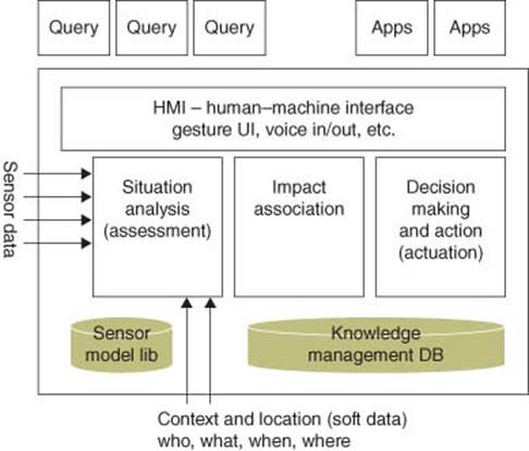
Figure 3.36 Sensor fusion software platform architecture
3.2.2 Smart Sensor Fusion Software Platform
This section introduces the concept of Sensor Fusion Platform (Figure 3.36). While more sensors are being integrated into microcontrollers to form smart sensor nodes, multiple sensors are still delivering sensing data that need to be processed and analyzed to result in decision-making and to trigger actions.
Sensor fusion takes hard sensor data fused with context-aware data such as location and owner data – referred to as soft data (who, what, when, where, etc.) – to perform situation assessment analysis; rule-based/knowledge-based decision making action can then be taken intelligently at the edge nodes. The C-IoT service platform leverages sensor fusion software framework components, to perform ubiquitous sensing and processing works transparent to the user. This will enable the development of C-IoT applications that interoperate among multiple point-solutions of Smart things. This will further drive the IoT market products to new heights.
The Sensor Fusion Platform architecture implements Smart senor analysis and decision-making [4]. Though traditionally implanted in the cloud with Big Data analytics, it is best to have distributed intelligence where some portions of the capabilities are distributed to local gateways and sensor nodes to minimize latency and improve response time.
The sensor-fusion platform consists of software modules that perform sensor data analysis, impact assessment, and knowledge-based approach decision-making. The framework is extensible, so new sensor data can easily be added to the sensor library and a new knowledge base can easily be added through learning. Additional data analytic applications can also be added to leverage the underlying engines and database.
3.3 Secured C-IoT Software Platform
IoT is here to stay, while the use of IPv6 is imperative to connect all devices globally via Internet. Security and networking safety is of primary concern.
In this section, we take an example of Smart Grid (USD multi-$ Billions markets) and describe the security concerns from Smart Meter to Concentrators, Concentrator to Substation, and Substation to Utility as a secured cloud-connected SCADA network. Although the degree of security may vary from segment to segment, the IoT security concerns remain the same, namely, cyber security, privacy, confidentiality, access authentication, firmware protection, and trusted boot, as well as protection from physical attacks and tampering. Figure 3.37 shows that end-to-end security must be considered.
All four pillars of network security mentioned below (specified by NIST SP 800 82, NERC, and IEEE) are addressed:
· Integrity. Prevent unauthorized modification of information
· Availability. Prevent DOS (Denial of Service) also known as the Intrusion Prevention System.
· Confidentiality. Prevent unauthorized access of information
· Non-repudiation. Prevent denial of action.
For each of the device in the Smart Grid, we suggest the platform solution (hardware and software) that can be used to make it secure and reliable.
This section includes the distribution grid automation with improved monitoring and visibility of utility’s huge distributed assets, which is one of the key motivations to provide significant return on investment (ROI) to the utility companies. For example, AMI with automated smart data concentrators and transmission line monitoring sensors can improve business operations such as DR to prevent brownout and does not require significant behavioral change by customers. The utility benefits are reduced downtime, faster service restorations, and rapid identification of faults for preventive maintenance.
The M2M and IoT end-to-end security solutions provided in this chapter can be extended to other areas like Smart Energy, Smart Health, Smart Transportation, Smart Factory, Business, and Residence (Smart Home) and make connected intelligence a reality.
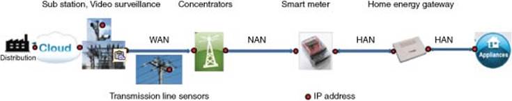
Figure 3.37 End-to-end security in the smart grid
3.3.1 Overview
In this section, we take a closer look at the security concerns at the communication layer, which predominantly, we believe, will be the IP-based network. As the data transmit over Internet, assured security in terms of Data Integrity, Confidentiality, and Non-Repudiation [16, 17] is essential. All devices must be protected against DOS Attacks, cyber attacks, vulnerabilities, and exploits. They also should be protected from malformed and bad traffic. Every IP address is susceptible to attacks and must be protected.
Smart Meters, Concentrators, and Transmission line sensors are deployed out in the open and thus must be protected from physical attacks and tampering. Such attempts have to be detected with the help of sensors and reported to the utility. Trusted boot and secure architecture must be provided to protect against unauthorized or malicious firmware upgrade.
Reliable two-way communication is essential for effective functioning of the smart grid. Having a mesh topology at the concentrator and at the substations can provide reliability and redundancy. Load balancing and failover (LBFO) can be achieved with two WAN connections at the concentrator and substations. For security, data are encrypted and for reliability RAID5 (redundant array of independent disks) can be implemented on upstream devices to protect loss of transient data.
We summarize the security concerns across the Smart Grid hierarchy as shown in Figure 3.38. Some examples of platform solutions, covering various aspects of security such as confidentiality, integrity, non-repudiation, and availability discussed are as follows:
· Smart Meter. Low footprint IP Stack with 6LoWPAN, Firewall, and IPSec-IKEv2 running on ZigBee SoC (System-on-chip) (Figure 3.39)
· Concentrator. IP Stack on Concentrator with 802.15.4 and 802.3 as in Figure 3.41
· Home Energy Gateway. With WiFi and Security Software (Figure 3.27)
· Utility and Substation Servers. With hardware accelerators for high performance.
3.3.2 C-IoT Security – Example of Smart Energy
Let us take a closer look at the security concerns at the communication layer of the Smart Grid which predominantly is expected to be the IP-based network as shown in Figure 3.37. As the data transmit over Internet, it has to be assured security in terms of Data Integrity, Confidentiality, and Non-Repudiation. All devices must be protected against DOS attacks, cyber attacks, vulnerabilities, and exploits. They also should be protected from malformed and bad traffic. Every IP address is susceptible to attacks and must be protected.
Smart Meters, Concentrators, Transmission line sensors are deployed out in the open and thus must be protected from physical attacks and tampering. Such attempts have to be detected with help of sensors and reported to the utility. Trusted boot and secure architecture must be provided to protect against unauthorized or malicious firmware upgrade.
Reliable two-way communication is essential for effective functioning of the Smart Grid. Having a mesh topology at the Concentrator can provide reliability and redundancy. Additional reliability of communication can be achieved by having two WAN connections at the Concentrator and Sub Stations for LBFO. Reliability can be further enhanced by implementing RAID5, Redundant Array of Independent Disks (https://en.wikipedia.org/wiki/RAID) on upstream device to protect loss of transient data.
Let us summarize the security concerns across the Smart Grid hierarchy shown in Figure 3.38 and propose platform solutions. Some examples of platform solutions covering various aspects of security discussed are:
1. Smart Meter. Low footprint IP Stack with 6LoWPAN, Firewall, and IPSec-IKEv2 running on ZigBee SoC.
2. Concentrator. IP Stack on Concentrator with 802.15.4 and 802.3.
3. Home Energy Gateway with WiFi and Security.
4. Utility and Substation Servers.
3.3.2.1 Securing Communication on the Smart Grid
This section covers the various layers of Smart Grid Hierarchical Architecture, security concerns for each layer, and platform solutions for each. Smart Grid security can be divided into the following segments/application blocks as shown in Figure 3.38:
1. Neighbor Area Network (Smart Meter to Concentrator)
2. Home Area Network (Appliances to Smart Meter or Home Energy Gateway)
3. Wide Area Network (Concentrator to Substation/Utility).
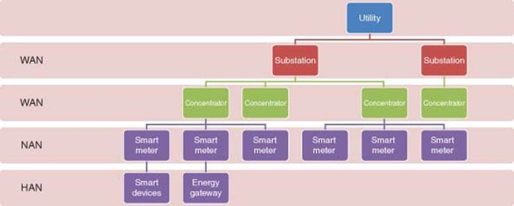
Figure 3.38 Smart grid hierarchical architecture
Each of these layers is described in the upcoming subsections in terms of their typical deployment, network topology, communication technology, security concerns for the devices in each segment, and protecting the data that are being communicated.
3.3.3 Securing NAN (Metrology-to-Concentrator)
NAN that connects the Smart Meter to the Concentrator is perhaps the most challenging in terms of vulnerability and security solutions for the following reasons:
1. Varied communication technologies options available are WiMAX, 3/4G, 802.15.4, and PLC. Although multiple technologies are available, most of them are wireless and suffer the drawbacks of wireless communication, where the data can be sniffed out and tampered with.
2. Low memory and other hardware resource constraints on the Smart Meter limit the feasibility of a robust security solution and restrict the options available for connection technologies.
3. Both Smart Meter and Concentrators are deployed outdoors and are susceptible to physical attacks.
These factors make NAN the weakest link in the Smart Grid and thus all factors impacting security need to be taken into consideration and addressed carefully.
This section takes 802.15.4 as an example of communication between Smart Meter and Concentrators and discusses the security issues and demonstrates how they can be addressed. The same can be applied to other modes of communication.
3.3.3.1 Platform Solution for Smart Meter
Since adoption of IPv6 is inevitable, in this example, 6LoWPAN/802.15.4 running on ZigBee SoC is proposed as a platform solution. The IP stack can be enhanced with rich security features integrating Firewall, IPSec [18], and IKEv2 [4] as shown in Figure 3.39. However, since the flash and RAM on the board are a low, lightweight version, the security application to fit into sub 100 K ROM and sub 100 K RAM is used. Further, VaultIC from InsideSecure (http://www.insidesecure.com/eng/Products/Secure-Solutions/Secure-solutions-products) can be used to secure the keys and certificates on the Smart Meter.
3.3.3.2 Network Topology and IP Addressing: NAN
For NAN, the Concentrator is considered to be the focal point, 802.15.4 coordinator, a Full Functional Device (FFD) and the Smart Meter, a Reduced Functional Device (RFD) with routing function. All Smart Meters in a given area or building are fully meshed with the Concentrator as Coordinator. The Concentrator assigns DHCP v6 IP addresses to the Smart Meters.
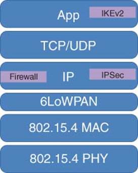
Figure 3.39 IP stack on smart meter with 6LoWPAN, firewall, and IPSec-IKEv2 on ZigBee SoC
3.3.3.3 Security on Smart Meter
The Smart Meter comes preloaded with shared keys or certificates [18, 19]. Alternatively, keys or certificates can be distributed in an out-of-band trusted mechanism. Since the IP address at the Smart Meter is dynamically assigned, an Internet Remote Access Client (IRAC) can be used for IKE exchanges. IKEv2 is used for Identity protection and for establishing Encryption and Authentication keys for the IPSec tunnel between the Smart Meter and Concentrator as shown in Figure 3.40. This combination of IKE and IPSec provides a secured NAN channel with data confidentiality and integrity. Sequence numbers in the IKE and IPSec help protect against replay and man in the middle attacks. Digital Signatures can be used for non-repudiation.
A list can be configured on the Firewall to allow only traffic from HAN to the Utility and vice-versa to pass through Smart Meter. Self-traffic can be limited only to allow IKE, DNS, DHCP traffic from the Concentrator to self and vice versa. Since the Smart Meter is expected to be actively communicating with the HAN devices, an access control list (ACL) should allow traffic from the HAN to Self and vice versa. DoS/Cyber-Attack check can be enabled on the Firewall to protect the Smart Meter from well-known attacks such as Ping Flood, Syn Flood, LAND Attacks, and Smurf Attacks. Any such attack detected should then be reported to Utility.
Secure Boot/Trusted Boot Architecture can be used to prevent malicious firmware upgrade. Anti-tampering sensors can be used to protect from physical attacks and tampering. Security concerns at the Smart Meter and the suggested solutions are summarized in Table 3.10.
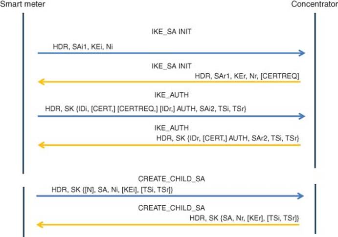
Figure 3.40 IKEv2 message exchange
Table 3.10 Summary of security on the smart meter
|
Security considerations |
Proposed solution |
|
Data integrity/authentication |
IPSec/IKEv2 |
|
Data confidentiality/encryption |
IPSec/IKEv2 |
|
Non-repudiation |
IPSec/IKEv2 |
|
Replay/man-in-middle attacks |
IPSec/IKEv2 |
|
Identity check |
IPSec/IKEv2 |
|
Availability/denial of service |
Firewall |
|
Access control |
Firewall |
|
Trusted/secure boot |
Secure boot arch |
|
Anti-tampering |
Anti-tampering sensors |
3.3.4 Securing Home Area Network (HAN)
HAN has multiple smart automated appliances such as the HVAC, washing/dryer machines, smart plugs, lighting, and multimedia connected to Smart Meter and/or Home Energy Gateway; the Smart Meters from multiple households are then connected to the data concentrator in the NAN for AMI. These appliances can be monitored and managed to use energy efficiently. This connected intelligence is provided by Smart Energy Solutions.
As shown in Figure 3.27, all smart appliances are connected to the Home Energy Gateway communicating over a ZigBee sensor network based on wireless 802.15.4. The Home Energy Gateway in turn connects to the Internet via 3G/LTE or DSL. It can also act as an 802.11.x Wireless AP.
3.3.4.1 Platform Solution for Home Energy Gateway
The Smart Energy Gateway [15] offers seamless connectivity with TCP/IP, 802.11n and ZigBee, and offers Firewall, NAT, Intrusion Detection System (IDS), IPS, Application Identification System/Monitoring System (AIS), and IPSec and IKE security services.
3.3.4.2 Network Topology and IP Addressing
As shown in Figure 3.27, all smart appliances are connected to the Home Energy Gateway communicating over a ZigBee sensor network based on wireless 802.15.4. Smart metering connectivity is achieved via ZigBee SE 1 or MBus. Smart appliances are managed via ZigBee HA1.0.
On the WAN side, the Home Energy Gateway connects to Internet via 3G/LTE or DSL using DHCP, whereby the service provider dynamically assigns an IP address.
The wireless gateway can also act as an 802.11.x Wireless AP on the LAN side connecting laptops, tablets, and so on and has secured trusted boot architecture.
3.3.4.3 Security on Smart Energy Gateway
The remote monitoring, control, and management of all in-home Smart Appliances happens through the Smart Energy Gateway. These data are sensitive and private and thus have to be provided security while traversing the Internet. This is achieved by establishing an encrypted secure channel for this traffic over the WAN. IPSec/IKEv2 or SSL can be used to provide this. In addition to confidentiality, this solution provides integrity, identity protection, non-repudiation, and protection against replay and man in the middle attacks. Tight access control policies can be implemented using Firewall to allow only authorized traffic to and through the gateway. DoS/Cyber Attack check can be enabled on the Firewall to protect the Home Energy Gateway and the internal network from well-known D/DOS attacks. Deep Packet Inspection (DPI) software can be used to control/rate-limit application traffic, for example, P2P, Social Networking Application. Security concerns at the Home Energy Gateway and the suggested solutions are summarized in Table 3.11.
Table 3.11 Summary of security on the home energy gateway
|
Security considerations |
Proposed solution |
|
Data integrity/authentication |
IPSec/IKEv2 |
|
Data confidentiality/encryption |
IPSec/IKEv2 |
|
Non-repudiation |
IPSec/IKEv2 |
|
Replay/man-in-middle attacks |
IPSec/IKEv2 |
|
Identity check |
IPSec/IKEv2 |
|
Availability/denial of service |
Firewall |
|
Access control |
Firewall |
|
NAT |
Firewall |
|
Application detection and control |
Freescale AIS |
3.3.5 Securing WAN (Concentrator-to-Substation/Utility Servers)
The communication between the Concentrator and the Substation can happen on one of several WAN technologies such as WiMAX, 3G/4G, or PLC. This communication is predominantly IP-based and data travel over the Internet. These sensitive bidirectional data that are from the Smart Meter to Utility and vice versa have to be protected from eavesdroppers to maintain confidentiality and integrity. As this link is critical to transfer real-time data, to ensure reliability it recommended having a failover connection. Critical messages from/to the meter must be prioritized over other traffic. The transient data on the concentrator have to be protected in case of crashes. Further, the Concentrator has to be protected from DOS attacks, bad traffic, and unauthorized access. As in the case of Smart Meters, since Concentrators are deployed outdoors, they have to be protected against physical attacks and tampering.
3.3.6 Platform Solution for Concentrator
The data concentrator [20] usually uses a low-power dual-core processor 667/800 MHz with up to 128 MB of NOR/NAND flash memory. The Security Accelerator, running Firewall, IPSec, IKEv2, and Application Identification Software can be used as a Concentrator as shown in Figure 3.41, which shows the data concentrator software stack delivering security and high performance.
This platform has 3G, WiFi, ZigBee WSN communication, and 3 Gb Ethernet capable ports to enable WAN/LAN communications and can communicate with Smart Metering devices via the industry standard DLMS (IEC 62056). It offers ZigBee wireless connectivity to meters and 3G Broadband to the Utility server. This device has an energy-efficient passive cooled design and has ruggedized, weather-resistant construction.
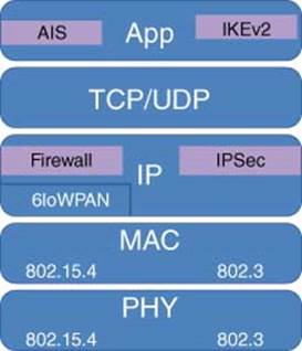
Figure 3.41 IP stack with 802.15.4 and 802.3 on data concentrator
3.3.7 Platform Solution for Substation/Utility Servers
The utility server is usually a multicore processor (>8 cores) [16] with Security Accelerator and Packet Matching Engine, running Firewall, IPSec, IKEv2, and AIS-Application Identification Software utility server delivers high performance with acceleration for the following functions:
1. Packet parsing, classification, and distribution
2. Queue management for scheduling, packet sequencing, and congestion management
3. Hardware buffer management for buffer allocation and deallocation
4. Encryption (SEC 4.0)
5. RegEx Pattern Matching (PME 2.0).
These devices can be “clustered” at the utility for load balancing and failover.
3.3.8 Network Topology and IP Addressing: WAN
The Concentrator’s WAN interfaces get DHCP v6 addressed from the Substation. This connection can be 3G/LTE WiMAX, PLC. For greater reliability, two links to the Substation can be provisioned by LBFO software (Table 3.12).
3.3.9 Security on the Concentrator and Utility Servers
The Concentrator plays a key role in aggregating data from the Smart Meters within its area and propagating it upstream to the Substation or Utility over the WAN link. These data traveling over Internet have to be encrypted for confidentiality and privacy. A secure IPSec VPN-tunnel can be established between the Concentrator and the Substation/Utility using IPSec/IKEv2. Since the IP address at Concentrator is dynamically assigned, IRAC can be used for IKE exchanges. This tunnel provides data confidentiality, integrity, non-repudiation, and protection against replay and man in the middle attacks.
Table 3.12 Security on the concentrator
|
Security considerations |
Proposed solution |
|
Data integrity/authentication |
IPSec/IKEv2 |
|
Data confidentiality/encryption |
IPSec/IKEv2 |
|
Non-repudiation |
IPSec/IKEv2 |
|
Replay/man in the middle attacks |
IPSec/IKEv2 |
|
Identity check |
IPSec/IKEv2 |
|
Availability/denial of service |
Firewall |
|
Access control |
Firewall |
|
Vulnerability and exploit |
Freescale AIS |
|
Trusted/secure boot |
Secure boot architecture |
|
Anti-tampering |
Anti-tampering sensors |
ACL can be configured on the Firewall to limit traffic from HAN to the Utility and vice-versa to pass through the Concentrator. The ACL should allow active communication traffic from the Smart Meter to and from the Concentrator. Firewall can be enabled to prevent DoS/Cyber Attack on the Concentrator and report to the utility.
The DPI software can be used to protect the Concentrator fromr bad and malicious traffic, DPI has a rich set of signatures to detect bad traffic, P2P application, vulnerabilities, and exploits of protocols like HTTP, FTP, and SSH. On detection of bad traffic, action can be set to drop traffic and inform utility.
The Secure Boot/Trusted Boot Architecture can be used to prevent malicious firmware. Anti-tampering sensors can be used to protect from physical attacks and tampering.
Security configuration on the Substation and Utility server is similar to that on the Concentrator. In cases where the WAN IP address of the Substation is configured manually and known to the Utility server, site-to-site IPSec can be configured instead of IRAC. Although most equipment including the surveillance cameras are in premises and are relatively well covered from physical attacks, it is recommended to have anti-tamper sensors. Transmission line sensors and anti-tamper sensors should be used where the lines run above ground to detect and report attack.
Quality of Service (QOS) must be configured on the Concentrator, Substation, and Utility server to prioritize critical messaging data over other traffic.
3.3.10 Summary on C-IoT Security
The secure platform solutions proposed in this chapter facilitate distribution grid automation, which provides improved monitoring and visibility of a Utility company’s large distributed assets. Such remote monitoring capabilities serve as a key motivation for the Utility as it results in significantly improved ROI. For example, AMI with automated smart data concentrators and transmission line monitoring sensors can improve business operations such as DR to prevent brownout and does not require significant behavioral change by customers. Benefits to the Utility companies are: reduced downtime, faster service restorations, rapid identification of faults for preventive maintenance (Table 3.13).
Table 3.13 Secure platform solutions for smart grid
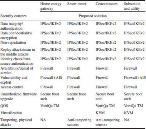
3.3.10.1 Summary
This section has covered security concerns at various layers of Smart Grid and proposed end-to-end high performance security solutions viewing Smart Grid as a system. All four pillars of network security (specified by NIST SP 800 82, NERC, and IEEE) are addressed in the proposed platform solution:
1. Integrity. Prevent unauthorized modification of information
2. Availability. Prevent DOS and Intrusion.
3. Confidentiality. Prevent unauthorized access of information
4. Non-repudiation. Prevent denial of action.
The secured M2M, IoT solution provided here is not limited to the Smart Grid; this model can be adapted and extended to other applications/markets such as the following:
1. Gas and water distribution
2. Health, residence, and transport
3. Building and factory automation
4. Securing enterprise and data centers.