COLLABORATIVE INTERNET OF THINGS (C-IOT). FOR FUTURE SMART CONNECTED LIFE AND BUSINESS (2015)
4
IoT Reference Design Kit
This chapter shows an IoT Reference Design Kit based on i.Mx6 processor that one could purchase online from CompuLab [1, 2].
http://utilite-computer.com/web/home
http://www.freescale.com/webapp/sps/site/prod_summary.jsp?code=RDIMX6SABREBRD&fsrch=1&sr=3&pageNum=1
Three models are available: single core Solo, Dual-core, or Quad-core.
The software image to download onto the board from www.freescale.com.
The IoT Reference Design Kit will provide the hands-on opportunity for one to experience the smart IoT software platform and IoT applications in delivery of various IoT products.
The Quick Start Guide provides the necessary step-by-step instructions to set up and demonstrate the IoT capabilities on the i.Mx6 board.
The software platform includes a Wireless access point (AP) Gateway that is easy to use and integrated with optimized open-source applications that support the use of wireless smart phones and smart tablets to perform remote monitoring, control of internet of things, and cloud services.
The following wireless-sensor-network (WSN)-based application can be demonstrated:
Home/Building Automation. Remote monitoring and control of appliances using a ZigBee-based Smart-plug modlet.
In addition, WiFi wireless-based media streaming applications can also be demonstrated:
Video Surveillance (NVR). Network Video Recording for video surveillance supports for wired or wireless IP cameras with auto detection.
Digital Living Network Alliance (DLNA) Server. Stream different video and music files from the wireless gateway board to multiple DLNA clients (e.g., Google TV, iPad, iPhone, and iPod touch).
4.1 Hardware Equipment List for the Demonstration
1. Hardware Platforms
a. Utilite i.Mx6 board or MCIMX6Q-SDB Sabre board.
http://utilite-computer.com/web/home
http://www.freescale.com/webapp/sps/site/prod_summary.jsp? code=RDIMX6SABREBRD&fsrch=1&sr=3&pageNum=1
b. SD Card containing boot image.
2. Wireless Smart Gateway Demo Peripherals
a. ThinkEco ZigBee USB dongle
http://utilite-computer.com/web/home
http://www.freescale.com/webapp/sps/site/prod_summary.jsp? code=RDIMX6SABREBRD&fsrch=1&sr=3&pageNum=1
b. ThinkEco ZigBee Modlet1http://www.amazon.com/ThinkEco-TE1010-Modlet-Starter-White/sim/B00AAT43OA/2. http://www.walmart.com/ip/ThinkEco-TE1010-starter-ThinkEco-Modlet-Starter-Kit-TE1010/21130985
c. Load for modlet (e.g., light and heater)
1. Media Streaming Demo Peripherals
a. WiFi IP Cameras – Axis Model M1011 (two sets) http://www.amazon.com/Axis-0301-004-0301004-M1011-W-camera/dp/B001PF3SDA.
b. Thin clients for DLNA, optional, not provided – iPhone or iPad with Fusion Stream app installed, iPod Touch with iMedia Suite installed, or Android tablet with Skifta installed.
2. Additional Peripherals
a. USB hub with external power (if using Mohave or 3G dongle in addition to ZigBee dongle)
b. 3G Broadband wireless Dongle – Huawei E160 O2 3G Dongle
c. AT&T SIM Card
d. Power Extension Cords (2)
e. Quick Start Guide and Poster
f. Large display monitor (user-provided)
g. Desktop or laptop computer with either the Microsoft XP (32-bit) or Window 7 Professional (32-bit) operating system, user-provided.
4.2 Software Required for Demonstration
Software pre-flashed/pre-loaded on SD Card
Boot image
Video files in.mp4 or H.264 formats (for DLNA demo)
Smart-plug, smart-meter.
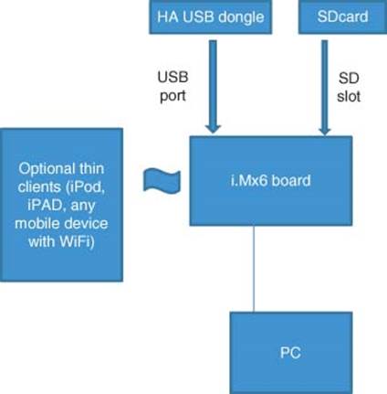
Figure 4.1 MCIMX6Q-SDB Sabre connectivity options
Installed Programs on PC
VLC for Windows (for NVR demo)
Axis IP Utility (for troubleshooting NVR)
Windows Media Player 12 (for DLNA demo)
TeraTerm (for troubleshooting).
To set up the I.MX6 Reference Platform (Figure 4.1):
1. Set up the Hardware according to Figure 4.2.
a. Power up the reference platform.
b. Configure the IP address of the network card of the Windows PC. Go to Start → Control Panel → Network and Internet → Network and Sharing Center.
c. If connecting to the reference platform wirelessly, select Wireless Network Connection. If connecting via Ethernet, make sure that the Ethernet cord is plugged into both the PC and reference platform’s LAN port. Select Local Area Network (Figure 4.3).
d. Click on Properties → Internet Protocol Version 4. If connecting to the reference platform wirelessly, select “Obtain IP address automatically.” If connecting via Ethernet, select “Use the following IP address,” and enter static IP address 192.168.1.54 (Figure 4.4).
e. If connecting wirelessly, connect to the reference platform’s SSID “I.MX60” using the password “12345678.”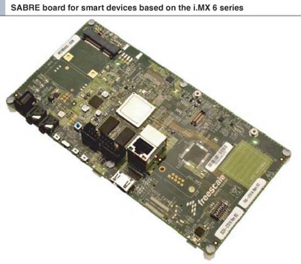
Figure 4.2 Basic setup diagram for I.MX6 board
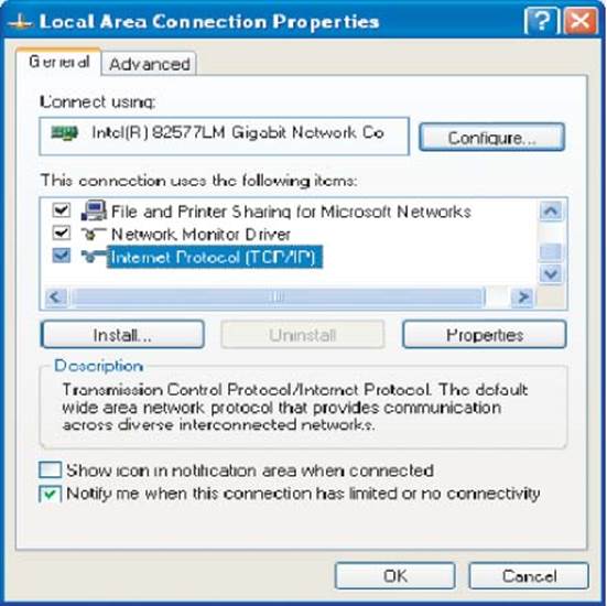
Figure 4.3 Local area connection properties
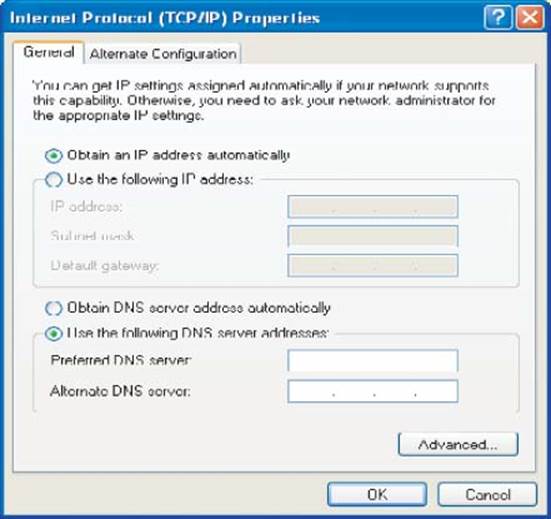
Figure 4.4 TCP/IP properties
f. Open the Internet Explorer (IE) browser, ensure that you have no proxies set and enter 192.168.1.1.
g. This opens the reference platform homepage; you will be prompted to set up/provide the username and password for future use.
i. Username: root
ii. Password: root
h. Check Remember the username and password checkbox for future use and press Enter. The webpage is shown as shown in Figure 4.5:
1. If the SSID of the board is not “I.MX60” or if there is no password, set these up using the reference platform homepage as shown in Figure 4.6:
a. Select Network → Wireless.
b. For “SSID,” enter “I.MX60.”
c. For “Password (PSK),” enter “12345678.”
2. If having trouble connecting wired devices to the box via an Ethernet switch, make sure that the Ethernet interface has been added to the bridge.
a. Use a computer to connect to the one box from “telnet 192.168.1.1” or TeraTerm.
b. Enter “ifconfig” to display interface configurations. Take note of the name for the Ethernet interface (e.g., eth0).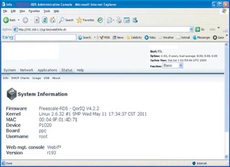
Figure 4.5 Reference platform homepage
c. Enter “brctl show” to display bridge information.
d. If the Ethernet interface is not displayed in the bridge information, add it using the command “brctl addif br-lan eth0” and the correct interface name found in Step 2.
e. Enter “brctl show” again to make sure that the Ethernet interface has been added.
4.3 Safely Power Off the Reference Platform
To power off the reference platform safely without the loss of data or without corrupting the files in the mounted devices, follow the following steps:
1. Connect the serial cable to the SPI interface of the board and the COM port of the PC
2. Connect to the board using TeraTerm
3. Hit enter to go to the “root@FSL#” prompt
4. Type “poweroff.”
Now, the board can be powered off.
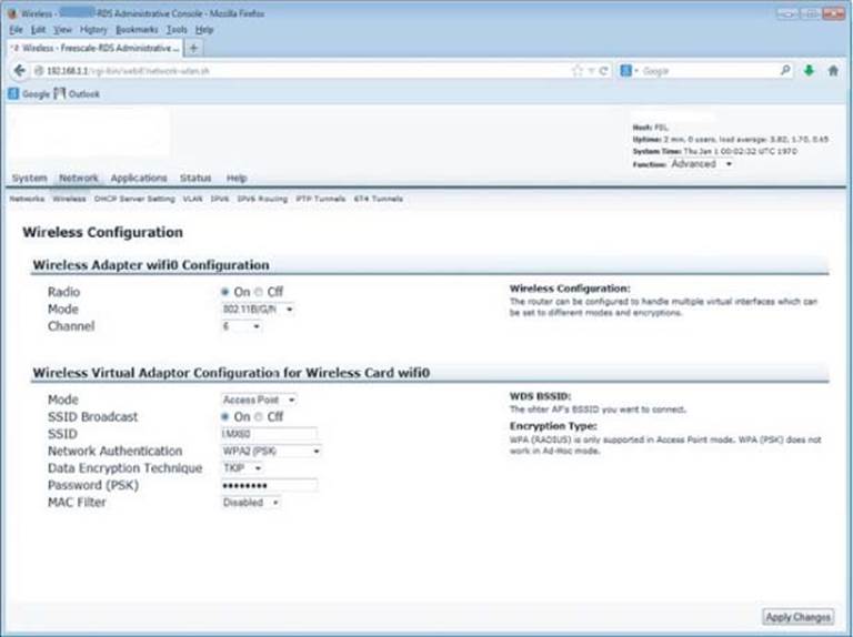
Figure 4.6 Wireless setup
4.4 ZigBee Home and Building Automation
This section describes the procedure to demonstrate the remote control of appliances through ZigBee WSN (e.g., Remote Power on/off device and monitoring power consumption of each appliance). Some applications examples are LED Lighting control, Smoke Alarm, garage-door opener, door-locks, window-shades for home, building automation, and so on.2
1. Insert the ThinkEco ZigBee dongle into the USB port of the reference platform as described in Figure 4.7.
2. Connect the ZigBee Modlet (smart plug) to a multi-socket power strip connected to the power meter and connect any electrical appliance (e.g., Light, Washer, and hair dryer) to the Modlet as shown in Figure 4.8.
a. Open Mozilla browser; type 192.168.1.1/home.html (Username: root, Password: root ).
b. It will pop up message “click OK and press the reset button on the modlet.”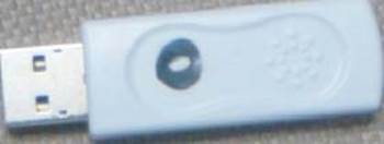
Figure 4.7 ThinkEco ZigBee Dongle
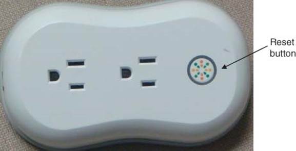
Figure 4.8 ThinkEco ZigBee Modlet
c. Click OK while pressing the “reset” button on the Modlet (Smart plug) at the same time and hold it for 8–10 seconds until the red blinking light around the reset button turns off.
d. If the light does not go off or if there is a message on the response page that said “Invalid message,” refresh the browser page and repeat the previous step until you get the correct acknowledgment. Note: sometimes, the correct message will pop up even if it did not connect. The light on the modlet is the best indication. If it is dark, then it has connected. Anything otherwise means it did not connect properly.
e. Wait for 30 seconds after the permit-join before trying to toggle the power on or off. To turn on the appliance connected to the upper socket (socket close to the button) of the Modlet, click “ON” in the backyard light pop-up window. To turn off the appliance connected to the upper socket (socket close to the button) of the Modlet, click “OFF” in the backyard light pop-up window.
f. The power consumed by both appliances will be displayed in the same pop-up window as well as main screen.
g. To perform the above-mentioned three tasks for the appliance connected to the lower socket of the Modlet, select “Dryer” instead of “backyard light.”
4.4.1 Troubleshooting ZigBee Home and Building Automation
· If the smart plug does not respond to toggling the power on or off, make sure that home.html is only open in one browser and you are toggling the correct outlet. Refresh the home.html page and repeat the permit-join.
· If encounter “no dongle detected,” the USB-fixed user space assignment for the dongle is incorrect. As a quick fix, remove the dongle from the USB hub and plug it directly into the board. As a permanent fix, get the updated 10-ftdi.rules file from the software download website and copy it to the SD card under the/etc/udev/rules directory.
4.5 Network Video Recorder (NVR) for Video Surveillance
This section describes the steps required to demo the NVR with auto detection of cameras.3
1. Ensure that the VLC player is installed, and Firewall and Proxy connections are disabled.
2. Open the IE browser and type 192.168.1.1 on the address bar.
3. Go to Applications → Network Video Recorder → Configuration page.
4. If the status of “Running” is No, click on Restart NVR and wait for restarting to finish (Figure 4.9).
5. Connect the real IP cameras to the i.Mx6 board.
6. Go to Applications → Network Video Recorder → Camera.
7. Click Auto Detect Camera, Cameras in the network will be automatically attached to NVR system. If no cameras are detected, follow the instructions in Appendix C to flash the camera (Figure 4.10).
8. Check the status of the cameras that are automatically detected by Applications → Network Video Recorder → Status. Make sure that all the visual cameras and real cameras are attached.
9. To watch camera videos, go to Applications → Network Video Recorder → Channel on the homepage.
10.Select 3 × 3 and select the camera to watch.
11.Click on the camera that you do not want to watch. Remove the check mark and click on
12.Save Changes.
13.In the pop-up window, click OK. 3 × 3 video stream windows should be shown.
14.If you want to make one video full screen, just double click on the video. If in one video full screen state, double click the video will return to the 3 × 3 video stream.
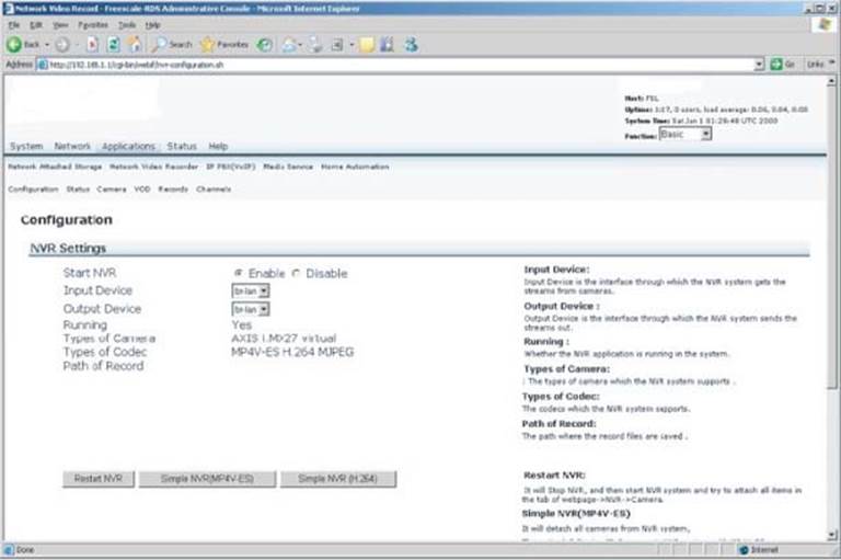
Figure 4.9 NVR configuration
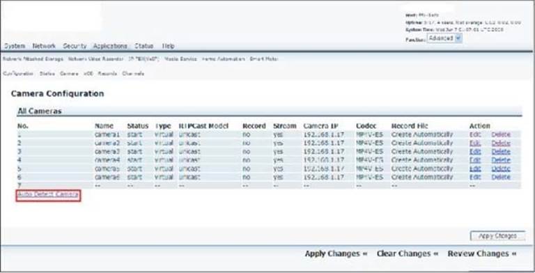
Figure 4.10 Camera configuration
For using the IPAD/IPHONE/IPOD:
1. Go to Settings and select the WiFi of the reference platform.
2. Go to “Streamer” application and select the address of the visual camera you want to view.
3. Go to Safari and type in the IP address taped on the live camera. This live camera has an IP address 192.168.1.x.4
4.5.1 Troubleshooting NVR
1. If a wireless camera is not connecting to the reference platform, you may need to flash the camera.
a. Connect the camera to a PC via Ethernet.
b. Open Axis IP Utility on the PC and refresh the list until the camera is found.
c. Make sure that the reference platform is powered on and broadcasting its SSID. Copy the camera’s IP address into a web browser (username: root, password: root).
d. Select Setup → Wireless and choose the reference platform’s SSID from the list.
e. Save the settings.
2. If a wired camera is not connecting to the reference platform through an Ethernet switch, you may need to add the Ethernet interface to the platform’s bridge. Refer to the troubleshooting part of Section IV Setup.
4.6 Internet 3G Broadband Gateway
This section describes the procedure to connect the i.Mx6 board to the internet via 3G.5
1. Once all the scripts are set up for the specific carrier, please open a browser and type in 192.168.1.1.
2. Navigate to the system tab and make sure that the board is functioning in router mode. If not, select it and apply changes.
3. In the terminal, type in: pppd call gprsdial & (to run this command in Background mode).
4. The board should try to connect to the internet via the 3G dongle. It may take some time. You can observe its connection by seeing if the LED on the physical dongle goes a solid color.
5. To test if it made the connection type in terminal: ifconfig ppp0.
6. If the interface ppp0 shows up in the console, then your dongle is connected.6
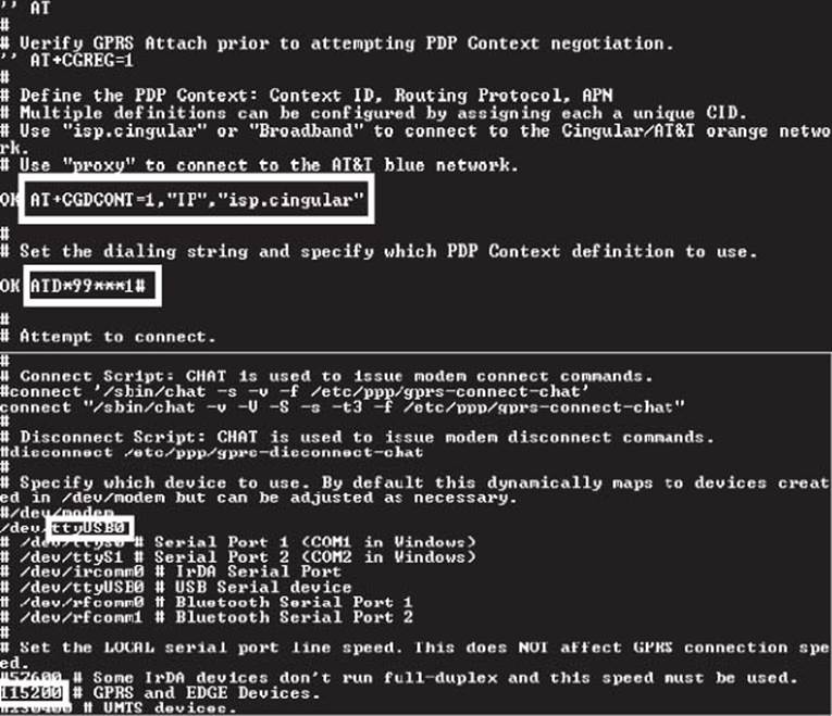
Figure 4.11 Setup for 3G service provider connections
4.7 UPNP
The following are the steps to enable UPNP features:
1. Enable UPNP features from web GUI.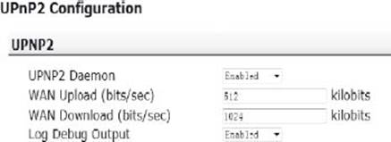
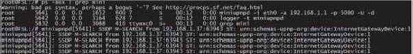
Figure 4.12 UPnP2
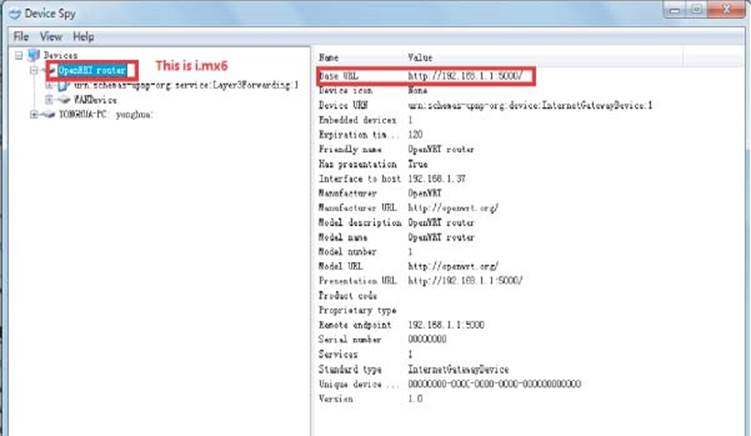
Figure 4.13 uPnP setup
2. At this moment, you can confirm from command line (Figure 4.12).
3. Download a UPNP tools. Such as Intel UPNP developer tools (download from here: http://opentools.homeip.net/dev-tools-for-upnp).
4. Install the UPNP tools on a PC, which connect i.mx6 board by any network (for example, WIFI).
5. Run device spy from the UPNP tools, see Figure 4.13.
4.8 Digital Living Network Alliance (DLNA) Media Server
This section describes the steps required to demonstrate the audio/video streaming capability, using DLNA application, of the Reference Platform.
4.8.1 Set Up Reference Platform as DLNA Server
DLNA server has been pre-installed on the reference platform and the SD card should have a partition with media files. The DLNA server will start when the board is booted and the reference platform will be ready to stream media files to any DLNA compliant clients. Please follow the instructions below to set up the DLNA clients.
4.8.2 Set Up DLNA Clients
1. For iPad
a. Check whether you have Fusion Stream installed on the iPad, otherwise this paid application needs to be downloaded from Apple Store. Make sure that the iPad connects to the correct SSID.
b. Start Fusion Stream application and click Refresh button (top left hand corner). Go to DLNA server → browse folder → All videos → select the video to play.
2. For iPhone
a. Check whether you have iMedia Suite installed on the iPhone, otherwise this paid application needs to be downloaded from the Apple Store.
b. Open iMedia Suite application; go to DLNA server → browse folder → All videos → select the video to play.
3. For PC with Windows XP
a. Install the VLC media player on the Window PC; you can download a free version online.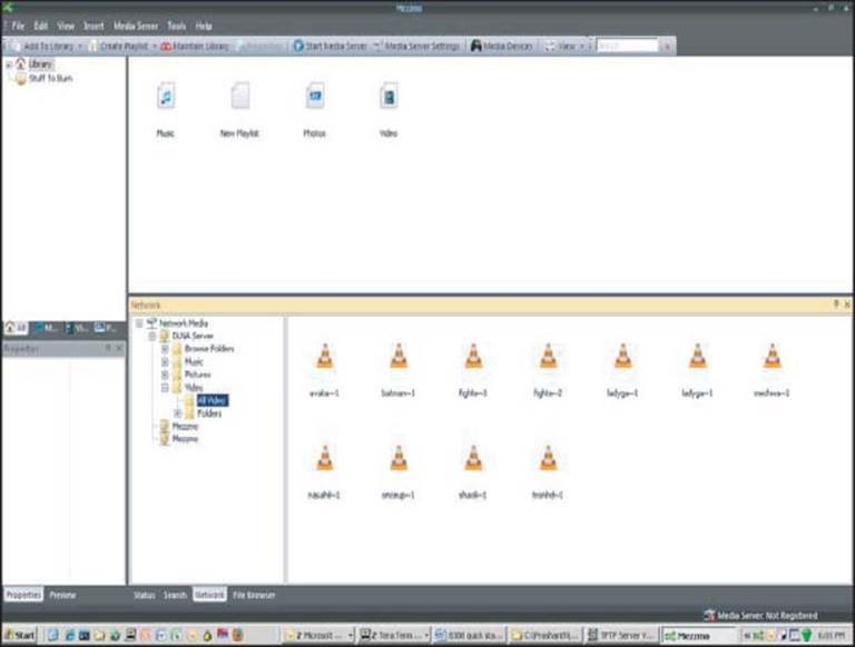
Figure 4.14 Mezzmo DLNA client on PC
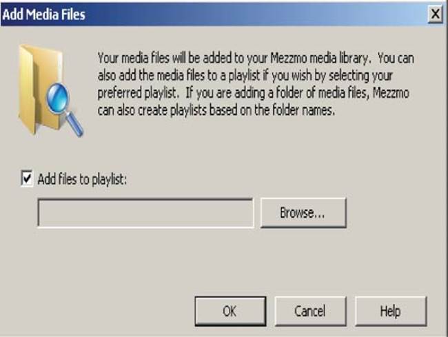
Figure 4.15 Adding media files to DLNA server
b. Install Mezzmo using Google search.
c. Open Mezzmo
i. Click the Network tab (on the bottom bar) and select Network Media /DLNA server/Video/All videos (Figure 4.14).
ii. Click create playlist and select the newly created playlist.
iii. Click on one of the video files and check Add files to playlist. Click OK (Figure 4.15).
iv. Select the playlist that you want to use. For example: library → new playlist.
v. Right click on the video file you want to play and select play.
vi. The video file will automatically open in the browser.
4. For PC with Windows 7
a. Windows Media Player 12 can also be used as a DLNA client.
b. In Windows Media Player 12, select DLNA server/Videos/All Videos.7
References
1. [1] Utilite (2014). Utilite i.Mx6 Board from Computlab, http://utilite-computer.com/web/home (accessed 10 December 2014).
2. [2] Freescale (2012). Freescale MCIMX6Q-SDB Sabre Board, http://www.freescale.com/webapp/sps/site/prod_summary.jsp?code=RDIMX6SABREBRD&fsrch=1&sr=3&pageNum=1 (accessed 10 December 2014).
1 Current modlets are rated only for 110 V, please use voltage adapter for 220/240 V source.
2 The home.html page can ONLY be open in ONE browser window at a time while running this demo. Only use Firefox, it does not work on IE.
3 Please install VLC for Windows. This must be done in IE ONLY.
4 If you do not know the IP addresses, then go to Network Video Recorder → Camera to view the IP address in “Camera IP” column.
5 We are using the Huawei E160 O2 dongle with an AT&T SIM card. To test the SIM card on a laptop, see Appendix D. If you use a different carrier, you will need to edit the scripts on the board under/etc/ppp/gprs-connect for your carrier connections (seehttp://zoom.custhelp.com/app/answers/detail/a_id/1030) and/etc/ppp/peers/gprsdial for your USB port and dongle type (Figure 4.11).
6 The Huawei E160 O2 dongle operates under GSM frequency bands: 850, 900, 1800, and 1900, and UMTS frequency band: 2100. If your carrier does not comply with those frequency bands, you will not be able to connect. Likewise, if you use a different dongle, make sure that the carrier and the frequency bands of the dongle match! A good rule of thumb is to check if you can connect via other devices first.
7 To check the CPU utilization and the processes those are running at any time: Go to System → Diagnostics and type top in the dialog box in front of the Command Run and click Command Run.
All materials on the site are licensed Creative Commons Attribution-Sharealike 3.0 Unported CC BY-SA 3.0 & GNU Free Documentation License (GFDL)
If you are the copyright holder of any material contained on our site and intend to remove it, please contact our site administrator for approval.
© 2016-2026 All site design rights belong to S.Y.A.