Software Engineering: A Methodical Approach (2014)
PART C. Software Design
The next five chapters will focus on the Design Phase of the SDLC. The objectives of this phase are as follows:
· To use the findings of the requirements specification to construct a model of the software that will serve as the blueprint to the actual development of the software product
· To thoroughly document this model
The activities of this phase culminate into the third major deliverable of a software engineering project — the design specification. Chapters to be covered include the following:
· Chapter 9 — Overview of Software Design
· Chapter 10 — Database Design
· Chapter 11 — User Interface Design
· Chapter 12 — Operations Design
· Chapter 13 — Other Design Considerations
Chapter 9. Overview of Software Design
This chapter provides you with an overview of the software design process. It is the first on your experience towards the preparation of the next major deliverable in a software engineering project — the design specification. The chapter proceeds under the following captions:
· The Software Design Process
· Design Strategies
· Architectural Design
· Interface Design
· Software Design and Development Standards
· The Design Specification
· Summary and Concluding Remarks
9.1 The Software Design Process
Software design is a creative process that is perfected with experience. It cannot be fully learnt from a reading a series of lectures or chapters of a book; however, guidelines can be given. The objective of the software design process is the construction of a model that is representative of the required software system. The model must be accurate and comprehensive; it must conform to established software design and development standards; it must also meet the quality factors discussed in chapters 1 and 3.
The design process starts with an informal design outline and undergoes several stages of refinement until a final model is obtained. The key deliverable from the design phase is the design specification (DS). Much feedback (backtracking) occurs among the stages of the design phase, as well as between the preparation of the requirements specification and the preparation of the design specification. In fact, it is a good idea to work on both deliverables concurrently, since changes in either will trigger adjustments in the other.
Figure 9-1 shows activities that go on during the design phase and what they lead to. Bear in mind that typically, some of these activities go on in parallel, rather than sequentially, so that feedback is constantly obtained and utilized. Below, these activities are clarified, but fuller discussion (on each activity) will follow in this and the next four chapters.
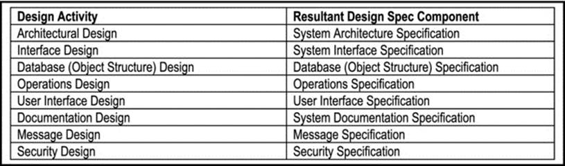
Figure 9-1. Important Software Design Activities
Architectural Design: Architectural design relates to the subsystems and/or modules making up the system, as well as their interrelationships. HIPO charts and system topology charts are useful diagramming tools that are used to represent the software model.
Interface Design: For each subsystem (module), its interface with other modules is designed and documented. The spin-off of interface design is the system interface specification, which must be unambiguous.
Object Structure Design: Object structure design relates to the data structures used in the system — object types (information entities), relationships, integrity constraints, data dictionary etc. Depending on the software engineering paradigm employed, it may be referred to as database design (in the case of traditional or hybrid approach), or object structure design (in the case of purely object oriented approach). Object structure design results in the object structure specification of the system. This will be further discussed in chapter 10.
Operations Design: This involves preparing operation specifications for all the operational components of the software. Operations design also involves categorization of the operations as well as design of algorithms used in the operations. It will be further elaborated in chapter 12.
User Interface Design: User interface design relates to screen design, menu structure(s), input and output design and in some systems, a user interface language. This will be further discussed in chapter 11.
Documentation Design: Documentation is an important part of software engineering. It includes all forms of product documentation (help system, users’ guide, system manuals, etc.) and will be elucidated in chapter 13.
Message Design: One important method of software communication with end users is via (error and status) messages. This aspect of software planning and construction is often ignored or belittled, to the horror of those who subsequently have to maintain the software. As you will see later (chapters 12 and 13), message design is a very important component of operations design.
Security Design: This relates to the various authority constraints that different users of the software product will have. How this is designed and the kind of security mechanisms that may be required will depend to a large extent on the type of software and its intended users. These issues will be addressed in chapter 13.
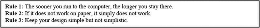
The importance of software design as a precursor to software construction cannot be over emphasized. Success in the former often leads to success in the latter. Additionally, flawed design inevitably leads to flawed development. Note however, that in both cases, the implication is not necessarily reversible: You can have a flawed construction after a good design. Here are three important rules worth remembering (the first was learned from a former professor, E. K. Mugisa; the other two were constructed out of experience).
9.2 Design Strategies
The design approach may be top-down or bottom-up. Top-down design is traditionally associated with function-oriented design (FOD) and bottom-up with object oriented design (OOD). This is somewhat misleading, however, since it is possible to have top-down design that is object oriented (this is sometimes recommended), and bottom-up design that is function oriented.
Until the early 1990s, FOD was the more widely used strategy. However, since the 1990s, OOD has gained widespread popularity, and is regarded today, as the preferred approach for many scenarios. Whichever strategy is employed, the quality factors mentioned in chapters 1 and 3 apply here. Quality must be built into the design from the outset. In the interest of clarity, these quality factors are restated here:

9.2.1 Function-Oriented Design
In FOD, the system is designed from a functional viewpoint, starting at the highest level, and progressively refining this into a more detailed design. The software engineer explicitly specifies the “what, wherefore and how” of the system; subsequent development must also deal with the “what, wherefore and how” as separate issues to be tied together.
FOD commences with the development of DFDs or POFs and other function-oriented system flow charts mentioned in chapter 6.
FOD conceals details of an algorithm in a function, but the system state (data) is not hidden. In fact, there is a centralized system state, shared by all functions. Further, changes to a given function can affect the behavior of other functions, and by extension, the entire system.
FOD leads to a system of interacting functions, acting on files and data stores (system state). Here, the principle of data independence (immunity of application programs to structural changes of an underlying database) is very important. As you will see later, violation of this principle could be catastrophic.
9.2.2 Object-Oriented Design
In OOD, the system is designed from an object-oriented viewpoint, and consists of objects that have hidden states (data) and methods; each object belongs to an object type. The software engineer explicitly specifies the “what” of the system (in the form of object types), but focuses on “encapsulating the wherefore and how” of the system into its objects.
This course recommends that your OOD should commence with the development of an information topology chart (ITC) or object flow diagram (OFD), then employ other object oriented diagramming techniques (such as O-R diagrams, UML diagrams, transition diagrams, activity diagrams and other OO techniques) mentioned in chapters 6 and 7.
OOD conceals details of an object by encapsulating these details in an object type, implemented as a class, but the behavior is not hidden. Moreover, changes to the internal structure of an object type (class) are isolated from all other system objects.
OOD leads to a system of interacting objects, each with their own internal structure and operations (interaction is facilitated through the operations). Here, the principle of encapsulation (information hiding) is very important. Encapsulation to the OO paradigm is what data independence is to the FO paradigm.
An object type is an entity that has a state (data structure) and a defined set of operations that operate on that state. The state is represented by a set of attributes, thus giving the object a structure. Object behavior is represented by operations, which are implemented by methods. The attributes and operations of an object (type) are referred to as properties. Object types are implemented as classes that encapsulate both data structure (attributes) and behavior (operations). These concepts are illustrated in Figure 9-2; this figure shows the UML (Unified Modeling Language) representation of an object type called Employee. Such a diagram is called an object structure diagram (OSD), or simply a class diagram.
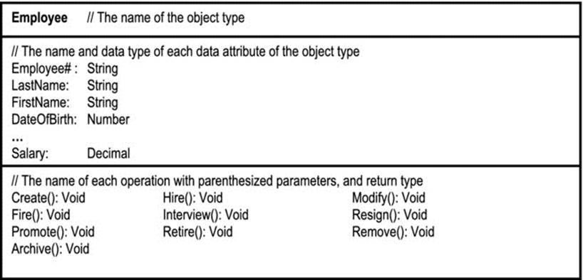
Figure 9-2. UML Diagram for an Object Type
Objects communicate with each other via messages. Messages are usually implemented as procedure (or function or method) calls with appropriate parameters.
OOD facilitates inheritance:
· Every object must belong to a class from which it inherits all its properties (attributes and operations). In object-oriented environments, a class is also an object, and may therefore inherit properties from another class called the super-class (also called the parent class orbase class). Inheritance hierarchies can therefore be established as illustrated in Figure 9-3. The inheriting class is called the sub-class, child class, or derived class.
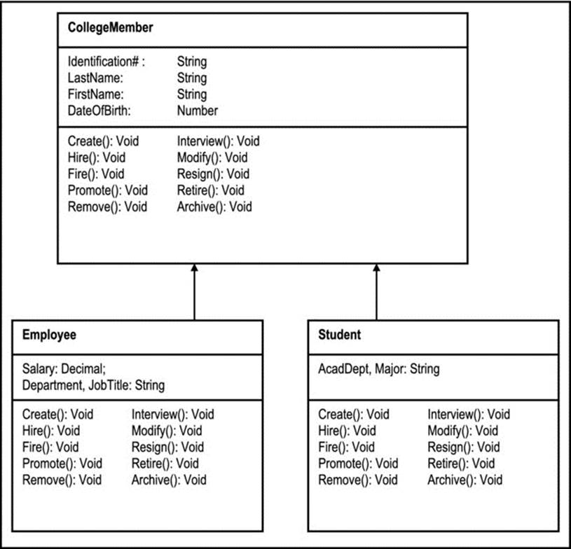
Figure 9-3. UML Diagram of a Type Hierarchy for a College Community
· A class could inherit properties from more than one super-class. This situation is referred to as multiple inheritance and is illustrated in Figure 9-4. Multiple inheritance, while providing flexibility, can be a source of confusion; for this reason, it is avoided in certain environments (e.g. Java). In your course on OOM, you will learn about workarounds, to avoid this situation (see appendix 5).
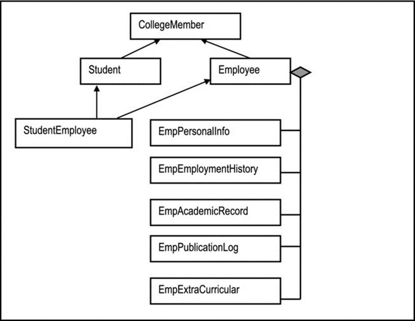
Figure 9-4. Abbreviated UML Diagram of an Inheritance Network for a College Community
· A class could be a super-class and a sub-class at the same time; this is also illustrated in Figure 9-4.
OOD facilitates amalgamation: An object type may be defined as the amalgamation of several constituent object types. This is illustrated in Figure 9-4, where Employee is the composition of EmpPersonalInfo, EmpEmploymentHistory, EmpAcademicRecord, EmpPublicationLog, and EmpExtraCurricular. If the amalgamation is optional (i.e. the constituents can exist on their own), it is called an aggregation, and the diamond shape is not shaded in; if the amalgamation is mandatory (i.e. the constituents cannot exist on their own), it is called a composition, and the diamond shape is shaded in (as in the figure). Quite often, the distinction is not very clear, and the software engineer has to make a judgment call on the matter.
Another important concept in object technology is polymorphism — the act of an object or operation taking on a different form, depending on the prevailing circumstances. To illustrate, consider an operation, Create(), which creates a college member object (refer to Figure 9-4). This operation could be made to behave differently, depending on whether the object being created is a CollegeMember, an Employee, or a Student.
Appendix 7 discusses OOM tools (please review); some of the more popular OO-RAD tools include Delphi, Rational Rose, and WebSphere; some of the more popular object oriented programming languages (OOPLs) include Java, C++, and Object Pascal (C++ and Object Pascal are really hybrid languages – supporting both procedural programming an OO programming). Note however, that OOD is independent of any programming language or OO-RAD tool used for software development. In fact, OOD is possible, even with traditional software development tools (though more effort would be required). It is also possible to do procedural programming in a hybrid programming environment such as C++ or Object Pascal.
By observation, most OO environments are actually hybrid environments, where an OO user interface is superimposed on a relational database (examples include DB2 and Oracle). This will be further elucidated later (sub-section 9.2.5).
9.2.3 The Unified Modeling Language
The Unified Modeling Language (UML) was developed by three leading prodigies in the area of object technology — James Rumbaugh, Grady Booch and Ivar Jacobson of Rational Software. This language was developed as an OO modeling language and is widely used in actual software development as well as research.
UML defines standards for object structure as well as object behavior (Figure 9-3 and Figure 9-4 employ some of the symbols used for object structure). You will be further exposed to this language in the upcoming chapters (see the recommended readings also).
9.2.4 Advantages of Object Oriented Design
Object oriented design brings a number of advantages to the software engineering arena. Some of the commonly mentioned ones are as follows:
· Reusability of code
· Easier maintenance
· Enhancement of the understandability of the system
· Higher quality design
· Design independence — classes which are independent of platforms can be developed
· Large, complex systems are simplified to interacting objects
· More powerful OO CASE tools and RAD tools have evolved. For many of these tools, the SDLC is simplified, merging actual design and development into what we call modeling, since many of the diagrams are said to be executable diagrams (meaning that actual code is generated from the diagram).
9.2.5 Using Both FO and OO Strategies
In large and complex projects, FOD and OOD can be skillfully employed to be complimentary rather than competing. Borrowing principles from both strategies often leads to better software design.
OOD seems most natural and beneficial at the highest and lowest levels of system design. At the highest level, it is more convenient to perceive a system as a set of interrelating component subsystems (which can be implemented as super-classes). At the lowest level, objects and operations can be implemented as programming classes.
FOD seems most natural and beneficial at the intermediate level, where the system can be viewed as a set of interacting operations (implemented as programs). Also, remember that at some stage, methods for objects must be specified; this often involves some amount of procedural programming.
Object technology does not make obsolete, all traditional (FO) approaches to software construction. Rather, it adds clarity, creativity and convenience to the software engineering discipline. In many hybrid environments, an OO user interface is often superimposed (made to access) a relational database. In fact, products such as Oracle, DB2, Delphi, Gupta Team Developer, etc. all reflect this approach.
One final note: FOD may or may not result in a change in the way users do their work. However, OOD usually results in a change in the way users do their work; and the users usually like the change.
9.3 Architectural Design
Complex systems are typically composed of subsystems or modules, which are themselves complete systems. These components must seamlessly integrate into the larger system. Architectural design addresses this challenge by determining what the components are and how they integrate and communicate with each other. The following are some considerations (factors) that influence system architecture decisions:
· Performance: If performance is a critical requirement, the architecture should seek to minimize the number of components that have to cross-communicate (i.e. employ more large-grain components than fine-grain components).
· Security: If security is critical, the architecture should provide a stringent security mechanism (preferably layered with the most critical resources at the innermost layer).
· Availability: If availability is a critical requirement, the architecture should include controlled redundancies by making components as independent as possible.
· Maintainability: If maintainability is a critical requirement, the architecture should employ fine-grain, self-contained components that can be readily changed.
These requirements typically do not synchronize with each other, so trade-offs will be necessary. Two issues of paramount importance in architectural design are resource sharing and system control. We will discuss these issues in the next two sub-sections, then close the section with a brief discussion on system components.
9.3.1. Approaches to Resource Sharing
There are four approaches to resource sharing:
· The Repository Model
· The Client-server Model
· The Abstract Machine Model
· The Component Model
Repository Model
In the repository model, all shared resources (data and operation) are stored in a central holding area (library). Each component has access to the repository. The repository may consist of more than one library of shared resources. It may contract or expand as the system is maintained during its useful life.
Examples of software systems that employ this approach include management information systems, CAD systems and CASE toolsets. Figure 9-5 also provides, by way of example, an overview diagram of the CUAIS project (mentioned in earlier chapters), assuming a repository model. In this approach, the central CUAIS database and controller subsystem interfaces with all other subsystems.
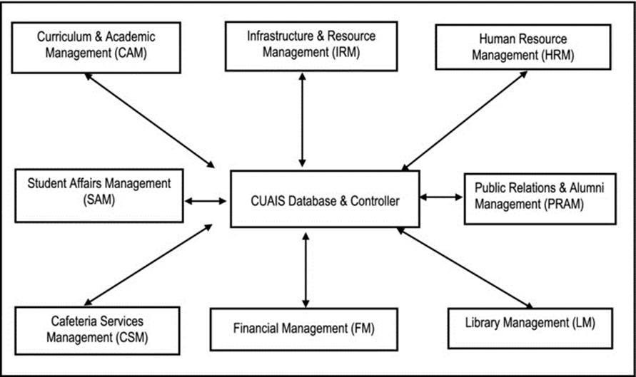
Figure 9-5. OFD for the CUAIS Project, Assuming Repository Model
Advantages of repository-based software include the following:
· Efficient data sharing; no need to explicitly transmit data for sharing
· High level of data independence: subsystems need not be concerned with how other subsystems use data
· Backup and recovery can easily be managed
· Integrating new resources is easy
Disadvantages of repository-based software include the following:
· Since subsystems have to agree on the data model, performance may be compromised.
· Evolution may be difficult, since the data model is standardized. Translating it to a new model can be costly.
· Flexibility in component subsystems may be lost on issues such as backup and recovery.
· It might be challenging to distribute the repository over a number of platforms.
Client-Server Model
In the client-server model, a set of independent network servers offers services which may be called on by members of a set of client systems. There is a server version of the software system that typically runs on a designated server machine, and a client version that runs on designated client machines. A network allows communication among clients and servers.
Examples of software systems that employ this approach include management systems with stand-alone components. Also, Figure 6-7 (of chapter 6) provides a partial overview of the CUAIS project without the central database. It is repeated here (as Figure 9-6) for ease of reference. In this approach, each subsystem would operate independently, but with the capability of communicating with other subsystems comprising the system.
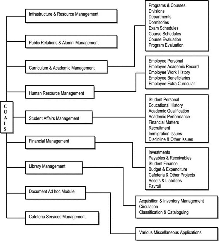
Figure 9-6. Partial Information Topology Chart for the CUAIS Project
Among the significant advantages of the client-server model are the following:
· A distributed architecture is facilitated. The implications of this are very profound and far-reaching, as you will discover in other advanced courses (electronic communication systems, database systems, and operating systems).
· The system can easily grow with additional clients and/or servers.
· The approach provides flexibility in how components communicate (via request, data transfer or service transfer).
· Productivity is enhanced.
The model faces three major challenges:
· More sophisticated software are required (but this is readily available) for resource management and communication among the components.
· Each server must take responsibility for backup and recovery issues.
· In situations where data is replicated in the interest of efficiency, maintaining the integrity of the data is problematic.
Abstract Machine Model
In this model (also called the layered model), the software is organized into layers, each providing a set of services. Each layer communicates directly only to the layer immediately above or below it.
By way of example, the open system interconnection model (OSI model) for communications protocols typifies a layered approach. Additionally, some operating systems and compilers are designed using the layered model.
The main advantage of the layered approach is that problems can be easily isolated and addressed. The main drawback is that the approach is not relevant to all kinds of system problems.
Component Model
The component model describes a pre-client-server approach where a set of component systems resides on a given machine, typically in a network environment. Obviously, this scenario can be easily facilitated in a client-server environment. But observe that it could also be implemented in a non-client-server environment, for example a minicomputer environment (precisely what used to happen prior to the introduction of client-server technology).
The component systems are made to communicate via interface programs and/or the introduction of controlled redundancy. To illustrate, suppose that System-A and System-B both use a database file, FileX. Let us assume that System-A owns FileX and therefore has update rights.System-B has a copy of FileX, namely FileXp, which it uses for data retrieval only. An interface program could be responsible for periodically copying FileX to FileXp, so that System-B “sees” accurate data.
Multi-component as well as single-user systems (on stand-alone machines) also typify the component model. The approach is relevant whenever a complex software system can be constructed by putting autonomous components together, or the system can be decoupled into identifiable autonomous components. Figure 9-6 would therefore also be applicable if the CUAIS project was being constructed using the component approach.
Two significant advantages of component-based systems as described here are local autonomy and fast response. Two drawbacks are the potential data integrity problems that they pose, and their limited scope of applicability.
With advances in OOM, we have witnessed a resurgence of a revised component model, called component based software engineering (CBSE). As mentioned earlier in the course (review section 1.4), CBSE promises significant benefits to the software engineering discipline.
9.3.2 System Controls
System control relates to how executing components are managed. There are two approaches that you should be familiar with:
· Centralized control
· Event-based control
In the centralized control approach, one system component is designated as the system controller and has responsibility for execution of the other components. Two models are prevalent:
· The call-return model is relevant to sequential systems: A component is invoked by a call; after execution, control goes back to the caller.
· The manager model is relevant to concurrent systems: One component controls starting, stopping and coordination of other components. Components may run sequentially or in parallel.
In the event-driven approach, the events control the execution of system components. Two models are prevalent:
· In a broadcast model, an event is broadcasted to all components. A component that can handle the event responds to it. Ethernet and Token Ring network protocols are good examples of the implementation of broadcast-driven control.
· In an interrupt-driven model, an interrupt handler responds to interrupts from various components and arbitrates which component will respond to the intercept. Operating systems software and real time systems are typically designed with interrupt handlers.
9.3.3 System Components
If the software engineering is in the FO paradigm, the system is broken down into a set of interacting functional components. If the OO paradigm is in vogue, the system is broken down into a set of interacting objects. In either case, consideration must be given the foregoing architectural design issues.
9.4 Interface Design
Very closely related to the architectural design is the system interface design (in fact, interface design may be incorporated into the architectural design). Here, the software engineer specifies exactly how the various system components will communicate.
In specifying how components will communicate, please note the following guidelines:
· Identify and specify all utility operations to be employed.
· Design intermediate data structures that may be required.
· Identify and specify system-wide utilities, for example date validation, error message processors, help retrieval processors, printing aids, etc.
9.5 Software Design and Development Standards
Software standards are very important in the design and development of software. The larger and more complex the project, the greater is the need for (and therefore benefit of) such standards.
Every software engineering company should have such standards; standards should also exist in companies where information technology (more specifically, the development of information systems) plays a critical role in the realization of corporate goals.
9.5.1 Advantages of Software Standards
The existence of software standards leads to a number of benefits, some of which are mentioned below:
· Enhancement of consistency in design and coding
· Enhancement of understandability of the system
· Enhancement of the maintainability of the system
· Improvement of the likelihood of reliable software
· Enhancement of good software documentation
· Imposition of some degree of order on software design and coding; programmers have to code to established standards, and not go off in unwieldy explorations
· Enhancement of a high level of efficiency and productivity during software construction
· Facilitation of a higher level of quality of the final product
· Facilitation of better project management
These advantages significantly contribute to the development of software systems of high quality. The converse is also true: failure to develop and observe meaningful software standards is a prescription for spaghetti code and mediocre software systems. It is through standards that the software engineering industry has been able to produce platform independent software systems that are immune to international borders and cultural barriers. Had there not been software standards, we would not have many things that we sometimes take for granted — the World Wide Web, operating systems, database systems, telephone services, television, radio, aviation, etc. In other words, without standards we’d all still be in the Stone Age, and software engineering as we know it would not exist.
9.5.2 Issues That Software Standards Should Address
The essential issues that software standards should address vary from one organization to another. They also vary with the category of software being developed. However, there are some fundamental ones that should always be treated. These are mentioned below:
· Naming of Non-database (Hardware Related) Objects: This includes the naming of workstations, printers, user profiles, output queues, etc. It includes all relevant objects related to the hardware used in the organization.
· Naming of Database Objects: This activity includes the naming of physical database files (tables), logical views, database stored procedures and triggers, etc.
· Naming of User Interface Objects: This includes the naming of operations (or application programs), menus and other user interface objects that may be employed in software construction. These objects will vary according to the software development tool being used.
· Database Design: Standards must be set in respect of database design. Chapter 10 and your course in database systems will elucidate this area.
· Screen and Report Layout: It is always a good habit to have standardized screen and report layouts for a given system. Chapter 11 will provide further clarification.
· Forms Design: Where the software requires manual inputs, or generates standard forms as output, these forms must be carefully designed. Chapter 11 will elucidate this area.
· User Interface Design: There should be guidelines with respect to the user interface (see chapter 11).
· Operation Specification: This relates to the method used to specify the required operations of a system. Chapter 12 will provide further clarification.
· Programming standards: This includes generic coding approaches, use of special keyboard keys (e.g. function keys), error handling, etc. Chapters 11 and 12 will provide further clarification.
· Software Development Tools: It may be necessary to define guidelines and benchmarks for the use of certain software development tools.
· System Documentation: There should be clear guidelines for software documentation in respect of system help, user manuals and other technical documents.
Figure 9-7 provides an example of an object naming convention that has been used by the current author on several software engineering projects. The inventory management system (IMS) project of appendix10 applies or prescribes this convention for several of the above-mentioned areas. Additionally, a slight modification of this convention is used in chapters 10 (Figure 10-9) and 12 (Figures 12-10 – 12-14).
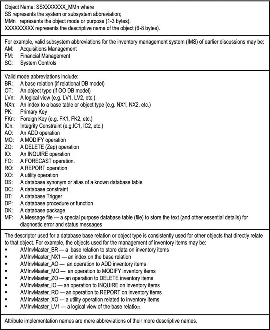
Figure 9-7. Proposed Object Naming Convention
9.6 The Design Specification
The design specification (DS) is another important deliverable for a software engineering project; it signals the end of the design phase (but remember, you may use a reversible life cycle model). Like the requirements specification, it is a formal, comprehensive document, providing further technical insights to the former. If the requirements specification is the initial blueprint of the software, the design specification is the final blueprint; it represents a refinement of the requirements specification, and contains information that is used for the construction of the software product.
![]() Note Some textbooks discuss one software blueprint in the form of a highly technical requirements specification. This course favors a less intimidating requirements specification as a precursor to a more detailed and technical design specification.
Note Some textbooks discuss one software blueprint in the form of a highly technical requirements specification. This course favors a less intimidating requirements specification as a precursor to a more detailed and technical design specification.
9.6.1 Contents of the Design Specification
The design specification includes details such as:
· Acknowledgements
· Introductory Notes
· System Overview
· Database Design Specification (chapter 10)
· User Interface Design Specification (chapter 11)
· Operations Design Specification (chapter 12)
· Architectural Design Specification
· Product Documentation Specification (chapter 13)
· Message Management Specification (chapter 13)
· Software Development Standards (possibly as an appendage)
· Refined Schedule for Software Development and Implementation (review chapter 8)
9.6.2 How to Proceed
You proceed to construct the design specification by using the requirements specification as your input. If the requirements specification is as accurate and comprehensive as it should be, then this is all you need. Figure 9-8 provides basic guidelines, but please note that this is not cast in stone: your approach may vary in some areas, depending on the nature of the project. Also observe that this figure is a refinement of the lower portion of Figure 7-10 (of chapter 7).
If at this point, you are still not confident about putting a design specification together, do not panic; after the next four chapters, and with practice, you will be in much better shape. The tools available for putting this deliverable together are very important. CASE tools (particularly OO-CASE tools) are excellent (review chapters 1 and 2). However, even in their absence, you can still be very effective with basic desktop processing tools.
Finally, please note that good software engineering will ensure that the requirements specification and the design specification both inform the final product documentation. Moreover, with experience, you will be able to work on both deliverables in parallel rather than in sequence (review section 9.1). An excellent product is a credit to excellent design, not a coincidence.
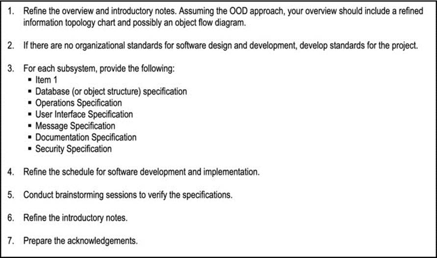
Figure 9-8. How to Construct the Design Specification
9.7 Summary and Concluding Remarks
It is time once again to summarize what has been covered in this chapter:
· The software design process consists of architectural design, interface design, object structure design, operations design, user interface design, documentation design, message design, and security design.
· The design may proceed as FOD or OOD. OOD relies on OO methodologies, and is the preferred approach for contemporary software systems.
· Architectural design addresses the issue of integrating the various components that comprise the software system. It addresses issues such as resource sharing and system controls. Alternate strategies for resource sharing include the repository model, the client-server model, the abstract machine model, and the component model. Alternate strategies for system control include the centralized control and the event-driven control. In many cases, interface design is combined with architectural design.
· Software design and development standards are absolutely necessary if software products of a high quality are to be developed.
· The design specification (DS) is the software engineering deliverable that results from the software design process. This becomes the blueprint for the software system. The software engineer must be clear on what goes into the DS and how to prepare it.
If you desire to learn more about OOD, please refer to the appendices (as well as the recommended readings). In particular, appendix 5 discusses categorizing object types in much more detail. For now, we must move on to other aspects of software design. The next few chapters discuss important components of the DS. As you proceed through these chapters, please reserve the liberty to periodically examine appendix 10 as this provides excerpts from a DS for the inventory management system of earlier mention.
9.8 Review Questions
1. Outline the software design process, explaining each aspect.
2. Compare function oriented with object-oriented design.
3. Discuss the four approaches to resource sharing as covered in the chapter. For each approach, cite advantages and disadvantages.
4. Examine Figure 9-7. What conclusions can you draw about the system represented? Also examine Figure 9-8. What conclusions can you draw about the system represented?
5. Discuss the importance of software design and development standards. Describe six important issues that these standards must address.
6. Which deliverable comes after software design? What is this deliverable comprised of? How would you proceed to construct such a deliverable?
9.9 References and/or Recommended Readings
[Lee, 2002] Lee, Richard C. and William M. Tepfenhart. Practical Object-Oriented Development With UML and Java. Upper Saddle River, NJ: Prentice Hall, 2002. See chapter 4.
[Martin, 1993] Martin, James, and James Odell. Principles of Object-Oriented Analysis and Design. Eaglewood Cliffs, NJ: Prentice Hall, 1993. See chapters 1 and 3.
[Peters, 2000] Peters, James F. and Witold Pedrycz. Software Engineering: An Engineering Approach. New York, NY: John Wiley & Sons, 2000. See chapter 7.
[Pfleeger, 2006] Pfleeger, Shari Lawrence. Software Engineering Theory and Practice 3rd ed. Upper Saddle River, NJ: Prentice Hall, 2006. See chapters 5 and 6.
[Pressman, 2005] Pressman, Roger. Software Engineering: A Practitioner’s Approach 6th ed. Crawfordsville, IN: McGraw-Hill, 2005. See chapters 9-11.
[Schach, 2005] Schach, Stephen R. Object-Oriented and Classical Software Engineering 6th ed. Boston, MA: McGraw-Hill, 2005. See chapters 7, 12 and 13.
[Sommerville, 2006] Sommerville, Ian. Software Engineering 8th ed. Reading, MA: Addison-Wesley, 2006. See chapters 11 – 14.
[Zhu, 2005] Zhu, Hong, Software Design Methodology: From Principles to Architectural Styles. Boston, MA: Elsevier, 2005.
All materials on the site are licensed Creative Commons Attribution-Sharealike 3.0 Unported CC BY-SA 3.0 & GNU Free Documentation License (GFDL)
If you are the copyright holder of any material contained on our site and intend to remove it, please contact our site administrator for approval.
© 2016-2026 All site design rights belong to S.Y.A.