Software Engineering: A Methodical Approach (2014)
PART G. Appendices
Appendix 4. Basic Guidelines for Object-Oriented Methodologies
In this chapter, we shall discuss some of the basic guidelines for OOSE. The chapter proceeds under the following subtopics:
· Object Identification
· End-User Involvement
· OO Diagramming
· Enterprise-wide Design
· Emphasis on OO-CASE Tools versus OO-Programming Language
· OO Modeling
· Summary and Concluding Remarks
A4.1 Object Identification
Skilled analysis is required in identifying object types. It is very important to identify object types that will make up the software system. In traditional software engineering, the primary question that the software engineer used to ask is, what do you do? In contemporary OOSE, the primary question that the software engineer seeks to ask and obtain an answer for is, what information do you manage, and how?
From your software engineering fundamentals, you recall that there are certain techniques of information gathering that are available to the software engineer, as he/she seeks to define the requirements of a software system (review chapter 5). Most of these techniques are applicable here; only, the focus is different. The most applicable techniques include the following:
· Analysis of Documents
· Interview
· Questionnaire
· Sampling and Observation
· Brainstorming
· Prototyping
· Observation
OOAD is not a replacement for good database design. In fact, for OOAD to succeed there must be good database design. As such, the principles of database design (learned in your database systems course) are not to be discarded. Rather, they form the basis for good OO design.
Several approaches to object identification (more precisely object type identification) have been proposed. The truth, however, is that these approaches do not offer any guarantee of successful identification of all object types required by a given system. Among the approaches that have been proposed are the following:
· Using Things to be Modeled
· Using Definitions of Objects, Categories and Types
· Using Decomposition
· Using Generalizations and Subclasses
· Using OO Domain Analysis or Application Framework
· Reusing Individual Hierarchies, Objects and Classes
· Using Personal Experience
· Using the Descriptive Narrative Approach
· Using Class-Responsibility-Collaboration Card
· Using the Rule-of-Thumb Approach
A4.1.1 Using Things to be Modeled
This is the preferred approach of experienced software engineers. It is summarized in two steps:
1. Identify tangible objects (more precisely, object types) in the application domain that are to be modeled.
2. Put these objects into logical categories. These categories will become super-classes.
In order for this method to be successful, the software engineer must make a paradigm shift to an object-oriented mindset. For this reason, software engineers who have not made that transition, usually have difficulties employing it.
The main drawback of this approach is that on the surface, it does not help in the identification of abstract (intangible) object types. Of course, the counter argument here is that with experience, identifying abstract object types will not be a problem.
A4.1.2 Using the Definitions of Objects, Categories and Interfaces
This technique assumes that the most effective way to identify object types is to do so directly, based on the software engineer’s knowledge of the application domain, as well as his/her knowledge of and experience in object abstraction and object categorization. Objects, categories (classes) and interfaces are identified intuitively.
This approach is very effective for the experienced software engineer who has made the paradigm shift of OO methodologies.
A4.1.3 Using Decomposition
This approach assumes that the system will consist of several component objects, and works very well in situations where this assumption is true. The steps involved are:
1. Identify the aggregate objects or categories.
2. Repeatedly decompose aggregate objects into their components until a stable state is reached.
There are two drawbacks with this approach:
· Not all systems have an abundance of aggregate object types.
· If the approach is strictly followed, one might end up proposing component relationships where one-to-many (or many-to-many) relationships would better serve the situation.
A4.1.4 Using Generalizations and Subclasses
This technique contends that objects are identified before their categories (object types). The steps involved are:
1. Identify all objects.
2. Identify objects that share the same attributes and services (operations). Generalize these objects into categories (object types).
3. Identify categories (classes) that share common resources (attributes, relationships, operations, etc.).
4. Factor out the common resources to form super-classes, then use generalization or specialization for all categories that share these common resources to form sub-categories (subclasses).
5. If the only common factors are service prototypes, use the interface to factor out these common factors.
The main advantage of this technique is reuse — it is likely to produce a design that is very compact, due to a high degree of code reuse.
The main disadvantage of the technique is that it could be easily misused to produce a design of countless splinter classes that reuse logically unrelated resources. This could result in a system that is difficult to maintain.
A4.1.5 Using OO Domain Analysis or Application Framework
This approach assumes that an OO domain analysis (OODA) and/or application framework of an application in the same problem domain was previously done, and can therefore be used. The steps involved are:
1. Analyze the existing OODA or application framework for the problem.
2. Reuse (with modifications where necessary) objects and/or categories as required.
The main advantage of this approach is that if such reusable components can be identified, system development time can be significantly reduced.
The main drawback of the approach is that it is not always applicable. Most existing systems either have incomplete OODA or no OODA at all. This should not be surprising since software engineering is a fairly youthful discipline. With time, this approach should be quite useful.
A4.1.6 Reusing Hierarchies, Individual Objects and Classes
This technique is relevant in a situation where there is a repository with reusable class hierarchies, which is available. The steps involved are:
1. Use the repository to identify classes and class hierarchies that can be reused.
2. Where necessary, adopt and modify existing classes to be reused.
3. Introduce new classes (categories) where necessary.
4. If the classes are parameterized, supply the generic formal parameters (this is not currently supported in Java).
The advantages and disadvantages of this approach are identical to those specified in the previous sub-section.
A4.1.7 Using Personal Experience
This approach is likely to become more popular as software engineers become more experienced in designing software via object technology. The software engineer draws on his/her experience in previously designed systems, to design a new one. The required steps are:
1. Identify objects, categories (classes) and interfaces that correspond to ones used in previous models that are in the same application domain.
2. Utilize these resources (with modification where applicable) in the new system.
3. Introduce new categories (object types) and interfaces where necessary.
This approach could significantly reduce the development time of a new system, while building the experience repertoire of the software engineer(s) involved.
Where the relevant prior experience is lacking, this approach breaks down and becomes potentially dangerous. Also, the approach could facilitate the proliferation of shoddy design with poor documentation, or no documentation at all. This could result in a system that is very difficult to maintain.
A4.1.8 Using the Descriptive Narrative Approach
The descriptive narrative technique, pioneered by Russell J. Abbott and popularized by Grady Booch, was widely used in the mid-1980s. It may be summarized as follows:
1. Prepare or obtain a descriptive narrative of the requirements of the system.
2. From the narrative, identify nouns, pronouns and verbs.
3. Nouns and pronouns are used to identify objects, and object types (categories), while verbs are used to identify operations (services) that are to be defined on the object types.
Figure A4-1 provides an illustration of a descriptive narrative, while Figure A4-2 shows what object types and operations can be determined from the narrative. Further refinement is left as an exercise.
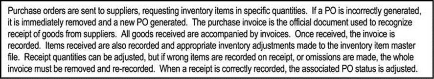
Figure A4-1. Descriptive Narrative for Purchase Order and Invoice Receipt Subsystem
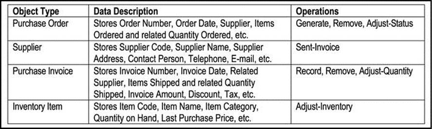
Figure A4-2. Object Types and Operations for Purchase Order and Invoice Receipt Subsystem
The main advantages of the technique are that it is easy to learn, understand and master; also, it is applicable to virtually any situation.
The technique has two main shortcomings:
· It may not always yield the correct set of object types, since nouns do not always translate to object types (classes). For example, the phrase “commit the transaction” contains a noun (“transaction”) and a verb (“commit”), but it would be foolhardy to model “transaction” as an object type, and “commit” as an operation.
· As the size and complexity of the system increases, the descriptive narrative becomes more voluminous. Conceivably, we could get to a point where in order to identify object types one has to first write several pages of narrative.
A4.1.9 Using the Class-Responsibility-Collaboration Method
A popular concept in object identification is responsibility-driven design, a term used to mean, we identify classes and determine their responsibilities. This must be done well before the internals of the class can be tackled.
The CRC (class-responsibility-collaborator) methodology, proposed by Kent Beck and Ward Cunningham (see [Beck & Cunningham, 1989]), defines for each class, its responsibilities and collaborators that the class may use to achieve its objectives (hence the acronym). The responsibilities of a class are the requests it must correctly respond to; the collaborators of a class are other classes it must invoke in order to carry out its responsibilities. In carrying out its responsibilities, a class may use its own internal methods, or it may solicit help via a collaborator’s method(s).
The CRC methodology is summarized in the following steps:
1. In a brainstorming session, identify object types (categories) that may be required for the system.
2. For each object type (category), construct a list of (possible) services to be provided (or operations to be performed on an instance of that object type).
3. For each object type (category), identify possible collaborators.
4. Identify missing object types (categories) and interfaces that should be added. To identify new object types, look for attributes and services that cannot be allocated to the current set of object types. To identify new interfaces, look for common service protocols.
5. Develop a CRC card for each object type and place them on a whiteboard (or desk surface). Draw association arcs from object types (classes) to collaborators.
6. Test and refine the model by utilizing use cases.
Figure A4-3 provides an illustration of a CRC card. The CRC card must be stored electronically as well as physically, to aid the design process. For instance, CRC cards can be easily classified, printed, and strung out on a table, during a brainstorming session, to assist designers with gaining a comprehensive overview of the system. Class names and responsibilities must be carefully worded to avoid ambiguities.
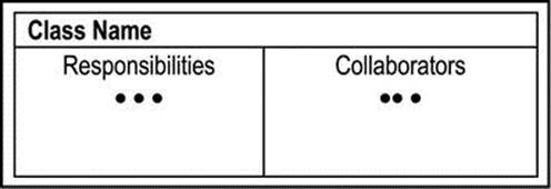
Figure A4-3. The CRC Card
The main advantages of the technique are:
· It is easy to learn and follow.
· When used properly, it helps designers gain a comprehensive overview of the system.
The main drawback of the technique is that it requires experienced software engineer(s) if success is to be achieved.
A4.1.10 Using the Rule-of-Thumb Method
This technique has been proposed by the current author, after having successfully tested it on several medium sized and large software systems over several years. The technique recommends identification of information entities (or object types) by applying appropriate information gathering techniques (review chapter 5). Once these object types have been identified, the technique then recommends an intuitive approach for identification of required operations for each object, based on the observation that in many situations, the essential operations required for an object type can be anticipated. Most objects (data entities) that make up a software system will be subject to any combination of the following basic operations:
· Addition of data items
· Update of existing data items
· Deletion of existing data items
· Inquiry and/or analysis on existing information
· Reporting and/or analysis of existing information
· Retrieval of existing data
· Prediction of future data based on analysis of existing data
Obviously, not all operations will apply for all object types; also, some object types may require additional operations. The software engineer makes intelligent decisions about these exceptions, depending on the situation. Additionally, the level of complexity of each operation will depend to some extent on the object type.
In a truly OO environment, these operations may be included as part of the object’s services. In a hybrid environment, the information entities may be implemented as part of a relational database, and the operations would be implemented as part of the superimposed user interface objects (consisting of windows, forms, etc.).
Like the other techniques, this rule-of-thumb approach does not guarantee success in identifying and outlining all the required object types for a software system in every scenario. However, it does guarantee a solid starting point toward achievement of this objective in many (perhaps most) scenarios.
A4.2 End User Involvement
OOSE must thoroughly involve end-users to ensure their satisfaction and acceptance. The software engineer or IT expert should not operate in a manner that is oblivious of the end-user. Rather, his/her role is to extract information needs from the end-users and model it in a way that the users understand and are satisfied with. Three types of workshops are common:
· JEM – Joint Enterprise Modeling
· JRP – Joint Requirements Planning
· JAD – Joint Application Design
Each session is guided by a facilitator (usually an IT professional, skilled in OOM). Key end-users do most of the talking. The facilitator does the modeling for end-users to see and accept or revise. The facilitator should be well experienced in system and software design, an excellent motivator and communicator; must have a good reputation that inspires confidence; a skilled negotiator.
Typical questions asked by the facilitator about object types:
· What are the data attributes?
· What operations are to be defined on this object type?
· What business rules apply here?
· What are the responsibilities of this object?
· What is needed to improve decisions?
· What control decisions could affect this operation?
· Could this operation be eliminated?
· Could this step be delegated to another object?
· Should this decision be made in a different place?
Martin makes a number of specific recommendations about workshops: Workshops typically last for no longer than a week at-a-time, and should not be allowed to spread out over an extended period of time. Nothing should be allowed to stall or slow down the progress of the workshop. Issues that cannot be resolved in a reasonable timeframe must be declared open (by the facilitator), and subject to subsequent analysis and/or discussion leading to satisfactory resolution (see [Martin, 1993]).
In order for a user workshop to be successful, thorough preparation must take place. The software engineers on the project must do their homework in obtaining relevant information, analyzing it, and preparing working models and/or proposal that will be examined and/or used in the workshop. Additionally, training of participants may be required prior to the workshop, in order to achieve optimum benefits. The training sessions should be carefully planned and administered. Here, the participants should be briefed on the expectations and activities of the workshops.
A4.3 OO Diagramming
The previous chapter (section A3.3) mentioned the diagrams that are used in OOM. For ease of reference, they have been repeated in Figure A4-4. For all diagrams, the following guidelines apply:
· Ideally, OO diagrams should be executable, i.e., it should be possible to generate code from the diagram (this is possibly via using an OO-CASE tool).
· Diagramming standards must be easy to learn.
· Diagrams should be easy to understand by software engineers as well as end users.
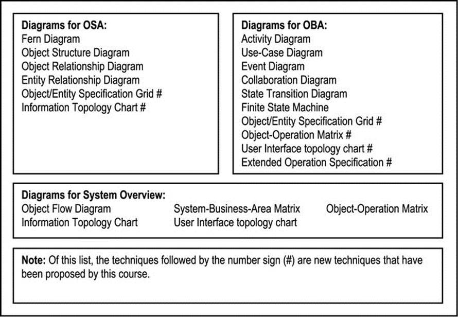
Figure A4-4. OOM Diagramming Techniques
A4.4 Enterprise-wide Design
Maximum benefits occur when analysis is done throughout the enterprise. OO information engineering (discussed in the previous chapter) enables a high-level overview model of the enterprise.
Enterprise-wide modeling has the following benefits:
· It leads to a more integrated information system.
· It leads to a higher level of reusability of code in the emergent system.
· It is a vital tool in enterprise redesign and reengineering.
In order to succeed, enterprise-wide design must be initiated by someone in authority, who commands the respect of the organization. In the early days, it was felt that enterprise-wide design had to be top-down, and never bottom-up. However, with the passing of time, the industry has come to understand that for optimum effectiveness, top-down approaches should be combined with bottom-up approaches. Top-down provides the management clout and support needed; bottom-up provides the information support that is absolutely necessary.
A4.5 Emphasis on OO-CASE Tools versus OO-Programming Language
In 1993, James Martin predicted that for object technology to succeed, the thrust must be on OO-CASE tools, which generate (preferably platform independent) code, instead of traditional HLL coding [Martin, 1993]. We have seen the fulfillment of this prediction. Writing code via traditional high-level language (HLL) still has its place, but if this is the sole strategy for software construction, the demands of the user (mentioned in appendix 1) will never be met.
The Java revolution, along with products such as the Rational product line, offer significant promise in this area. Other prominent products include Delphi, C++ Builder, WebSphere, etc. (appendix 7 will discuss OO software development tools).
Assuming the use of CASE tools over traditional programming for future software development, the following guidelines apply:
· The code generated by CASE tools must be accessible: A software engineer or programmer must be able to access the code and modify it to introduce additional functionality to the software product being developed.
· The code generated by CASE tools must be portable and preferably platform independent.
· CASE tools should preferably facilitate the creation and maintenance of a repository, which stores information on all previously defined generic classes and methods. This will enhance code reusability.
· With repository-based development, paper is no longer the primary form of documentation.
· With OO-CASE tools, software development time may be reduced by 20% – 60%.
A4.6 OO Modeling
As mentioned earlier, OO modeling has two aspects, which may be examined separately — structure and behavior. Figure A4-5 illustrates an OO modeling hierarchy based on Martin’s OO modeling pyramid. The figure shows how these two aspects relate to the OO modeling paradigm [Martin, 1993]. Here, two sides of the IS pyramid of appendix 3 are emphasized — object structure and object behavior.
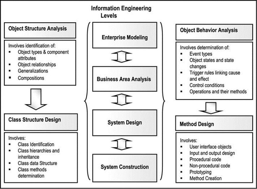
Figure A4-5. OO Modeling Hierarchy
Object structure analysis (OSA) utilizes diagrams that convey object types, object associates, compositions and generalization. Correspondingly, class structure design includes class identification, inheritance and data structure.
Object behavior analysis (OBA) utilizes object flow diagrams, state diagrams, event diagrams, and operation specifications. Correspondingly, method design includes operation identification and method creation.
In the traditional approach to software system acquisition, there are distinct, disjoint phases. Different diagrams and standards are used at each phase. Object technology uses one consistent model that is revisable. One set of diagrams and standards is employed. Consequently, the risk of having design errors is significantly reduced.
Again referring to Figure A4-4, notice that the figure lists the diagramming techniques that are best suited for OSA, OBA, and system overview respectively. Several of these techniques are based on the UML notation, and are very easy to learn. Moreover, most contemporary software planning and development tools support UML. Once these techniques are learned and mastered (through experience), software design and construction (particularly the object-oriented way) becomes an exciting and fulfilling discipline that affects the life of the practicing software engineer, as well as countless others.
A4.7 Summary and Concluding Remarks
Here is a summary of what we have covered in this chapter:
· Object identification is critical to defining the structure of the system being designed. Among the various object identification techniques that have been proposed are the following: using things to be modeled; using definitions of objects, categories and types; using decomposition; using generalizations and subclasses; using OO domain analysis or application framework; reusing individual hierarchies, objects and classes; using personal experience; using nouns and verbs; using class-responsibility-collaboration cards; using the rule-of-thumb method.
· OOAD must thoroughly involve end-users to ensure their satisfaction and acceptance. Three types of workshops that are common are JEM (Joint Enterprise Modeling), JRP (Joint Requirements Planning), and JAD (Joint Application Design).
· Mastery of OOM diagramming techniques is paramount.
· System design must be enterprise-wide within the context of OOIE.
· In constructing contemporary software, emphasis should be placed on OO-CASE tools rather than traditional HLLs. Sole reliance on the latter will not facilitate meeting the demands of the users.
· OO modeling involves two aspects — object structure analysis (OSA) and object behavior analysis (OBA). OSA relates to how the object types are comprised and their interrelatedness. OBA relates to the analysis and design of operations defined on each object type.
To proceed with our OO approach to software engineering, we need to delve deeper in the matter of OSA and OBA. The next chapter discusses the former.
A4.8 References and/or Recommended Reading
[Beck & Cunningham, 1989] Beck, Kent and Ward Cunningham. “A Laboratory for Teaching Object-Oriented Thinking.” OOPSLA'89 Conference Proceedings October 1-6, 1989, New Orleans, Louisiana. http://c2.com/doc/oopsla89/paper.html.
[Due’, 2002] Due’, Richard T. Mentoring Object Technology Projects. Saddle River, New Jersey: Prentice Hall, 2002. See chapters 3-6.
[Lee, 2002] Lee, Richard C. and William M. Tepfenhart. Practical Object-Oriented Development With UML and Java. Upper Saddle River, NJ: Prentice Hall, 2002. See chapter 4.
[Martin, 1993] Martin, James and James Odell. Principles of Object Oriented Analysis and Design. Eaglewood Cliffs, New Jersey: Pretence Hall, 1993. See chapters 4 and 5.