Software Engineering: A Methodical Approach (2014)
PART G. Appendices
Appendix 5. Categorizing Objects
This chapter focuses on how we categorize objects. As we work towards constructing a software system via the object-oriented paradigm, identifying the object types and their interrelationships becomes very crucial.
The chapter includes:
· Identifying Object Relationships
· Fern Diagram
· Information Topology Chart
· Object Relationship Diagrams
· Representing Details About Object Types
· Avoiding Multiple Inheritance Relationships
· Top-Down versus Bottom-Up
· Summary and Concluding Remarks
A5.1 Identifying Object Relationships
To identify relationships, you have to know what a relationship is, and what types of relationships there are. In the OO paradigm, we define a relationship as an association among two or more object types. There are seven types of relationships:
· One-to-one (1:1) relationship
· One-to-many (1:M) relationship
· Many-to-one (M:1) relationship
· Many-to-many (M:M) relationship
· Aggregation relationship
· Component relationship
· Inheritance (generalization) relationship
The first four types of relationships are referred to as traditional relationships because up until the OO model for database design gained preeminence, they were essentially the kinds of relationships that were facilitated by the relational database model. In the OO paradigm, they are referred to as links. Observe also, that the only difference between a 1:M relationship and a M:1 relation is a matter of perspective; thus, a 1:M relationship may also be described as a M:1 relationship (so that in practice, there are really three types of relationships). Put another way:

Your course in database systems allows you to gain mastery in how these relationships are represented and implemented in the relational model for databases. If you have not taken that course, you should plan on doing so in the near future. If you have already taken the course and need to review, please do so. Chapter 10 of this course also provides an overview of relationship identification (albeit from a database perspective). The rest of this review focuses on some other techniques used in the OO paradigm.
A5.2 Fern Diagram
Fern diagrams are useful in depicting the object types that make up the system. A fern diagram may be tree structured (where there is no multiple inheritance) or network structured (where there is multiple inheritance). It typically includes aggregation, component and inheritance relationships but makes no distinction among them.
The fern diagram is usually read from left to right or top to bottom (no arrowheads required). It is a useful technique, particularly where system is large and complex. Figures A5-1 and A5-2 provide two illustrations.
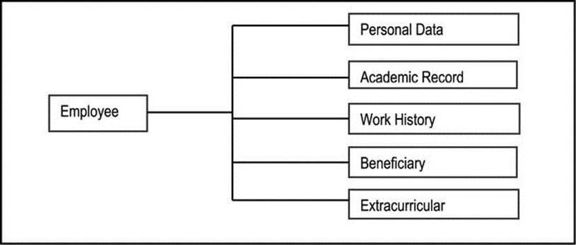
Figure A5-1. A Tree Structured Fern Diagram
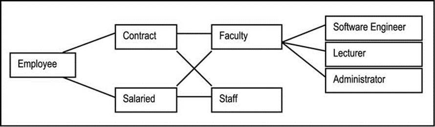
Figure A5-2. A Network Structured Fern Diagram
Advantages of fern diagrams:
· They are easy to draw and maintain.
· They are useful in assisting in the categorization of objects.
The main drawbacks of the fern diagram are:
· No distinction is made between a subtype relationship and an aggregation relationship.
· Neither does it show other types of relationships.
· The diagram may become cluttered and unwieldy as the system’s size and complexity increases.
Sometimes it is useful to show instances on a fern diagram. This is done with the aid of broken lines. In the main, showing instances is impractical, but there are times when instances may have particular meaning in the design as in Figure A5-3, where Bruce is a software engineer andKaren is a staff member.
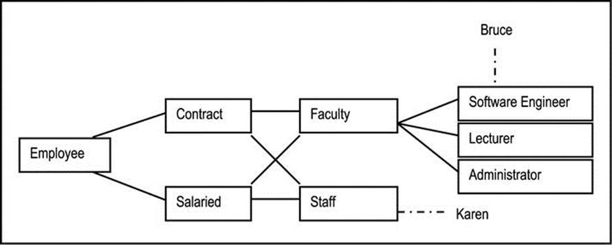
Figure A5-3. Fern Diagram with Instances
A5.3 Information Topology Chart
The information topology chart (ITC) is a conceptual representation of component subsystems and object types (or information entities) of the software system. The ITC shows information levels of the software system in a top-down manner. The system name appears at the highest level. Subsystems appear at the next level, followed by information entities (or object types). If the software system contains no subsystems, then the information entities (or object types) appear at the second level. Optionally, data elements (attributes) may be included at the lowest level. The technique presents information to be managed in the system in a logical and modular way, and therefore allows for easy analysis and identification of omissions or redundancies.
The ITC is particularly useful in providing a global view of the system, including all significant components. It is useful for analysis and specification, as well as the design phases of the SDLC. As such, it illustrates component relationships, but no attempt is made at representing inheritance, or other types of relationships. Figure A5-4 illustrates a portion of an ITC for the generic Inventory Management System (IMS) project or earlier mention. A more detailed diagram appears in appendix 10.
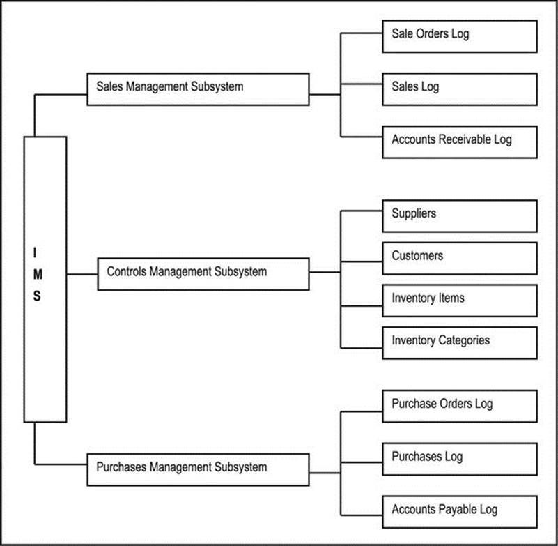
Figure A5-4. Partial Information Topology Chart for an Inventory Management System
At a cursory glance, you may be tempted to compare the ITC with the fern diagram. Here is the difference: The fern diagram is used to illustrate object categorization (including component and inheritance relationships). In contrast, the ITC’s primary purpose is to illustrate how information will be classified and managed in the software system. As such, its focus is comprehensive coverage of all object types (or information entities) for the software system being modeled. Component relationships are typically covered but that is not the primary focus of the technique. The ITC also differs from the HIPO chart (of chapter 6) in that whereas the HIPO chart is a functional representation of processes in traditional software systems, the ITC has a different focus as explained above.
Advantages of the ITC are as follows:
· The ITC is not just applicable in OOAD, but can also be used in function-oriented design (FOD).
· It is easy to draw and maintain.
· It is very effective in presenting a comprehensive perspective of the system.
· It is a powerful analysis and documentation tool.
Two limitations of the technique are worth noting:
· In presenting component information entities (object types), aggregation relationships are often incidentally represented. However, no distinction is made between subtype relationships and aggregation relationships.
· By intent, the technique does not show other types of relationships.
A5.4 Object Relationship Diagrams
An object-relationship diagram (ORD) is similar to an entity-relationship diagram (ERD). The conventions used in both techniques are also similar for the most part. However, there are a few subtle differences relating to how relationships are represented. Please review chapter 10 (section 10.2.5) to refresh your memory on these differences.
OOAD does not replace good relational database design; rather it presumes it. There are, however, times when the two tend to contradict. In such cases, experienced judgment is required. It should be noted however, that the scenario of an OO-GUI being superimposed on top of a relational database is a widely popular configuration.
It may become necessary to introduce abstract object types (classes) in the design, in the interest of generalization. An abstract object type is an object type that has no direct instances but whose descendants have direct instances. Artificially introduced abstract types are normally used as a mechanism for promoting code reuse. This in essence is the Principle of Occam’s Razor: “two types should not be used where one will suffice” (see [Martin, 1993]).
The preferred standard for ORDs is the UML notation as described in chapters 9 and 10 (sections 9.2.2 and 10.2.5). This notation is supported in many contemporary OO-CASE tools. Where an OO-CASE tool is not readily available, drawing on ORD becomes impractical for large, complex systems. Every effort should be made to have an ORD for the software system. However, if this is infeasible due to limited resources, alternate means should be explored. One alternative that was discussed in chapter 10 and illustrated in appendix 3 is the object/entity specification grid (O/ESG).
A5.5 Representing Details about Object Types
Two standard methodologies for representing details about object types are the object structure diagram (OSD) and the class-responsibility-collaboration (CRC) card. A third approach is the O/ESG, which was discussed in chapter 10 (section 10.2.6) and illustrated in appendix 3. A fourth possibility is to extend the information topology chart (ITC) of earlier discussions to include attributes of each object type (or information entity); if incorporated into an OO-CASE tool, this could be quite useful. We shall briefly discuss the two standard approaches.
A5.5.1 Object Structure Diagram
The object structure diagram (OSD) is just an alternate term for the class diagram, so you have already been introduced to it from your object-oriented programming, and the review provided in chapter 9 (section 9.2.2). The recommended standard for OSDs is the UML notation. Typically, you will not find stand-alone OSDs for each object type comprising a system; rather, OSDs are incorporated in ORDs in order to convey useful information about the structure and interrelatedness of object types comprising a software system. Note however, that from time to time, it might be necessary to highlight the OSD for a set of object types. One case in point would be where a software engineer is desirous of writing or modifying code for a specific set of object types. In situations where you are modeling a database, alternate methodologies such as ERDs and/or O/ESGs may be considered.
OSDs and ORDs (via the UML notation) are widely supported in contemporary software planning and development tools (review section 2.4.5 of chapter 2). The technique itself is quite simple and easy to follow. Figure A5-5 shows an excerpt of the ORD for the CUAIS project of earlier mention (copied from Figure 9-3 for ease of reference), depicting an inheritance relationship between object type CollegeMember (the super-type) on the one hand, and object types Employee and Student (the subtypes) on the other.
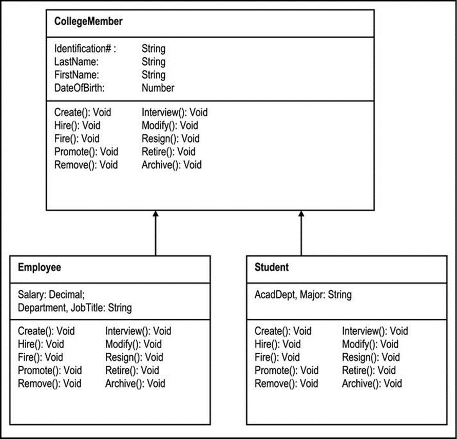
Figure A5-5. ORD Depicting Inheritance in a College Community
Moving to another example, Figure A5-6 illustrates a configuration of five object types in what is called a star schema: A central object type (SalesSumary) is surrounded by a set of object types (in this case Location, TimePeriod, Product, and ProductLine). Each object type forms a 1:M relationship with the central object type. The star schema represented in the figure relates to tracking sales by a marketing firm based on dimensions such as time, location, product line, and product. Star schemas are widely used in data modeling. However, a full discussion of this topic is not necessary for this course. For more information on the matter, see the recommended readings ([Foster, 2010] and [Hoffer, 2007]).
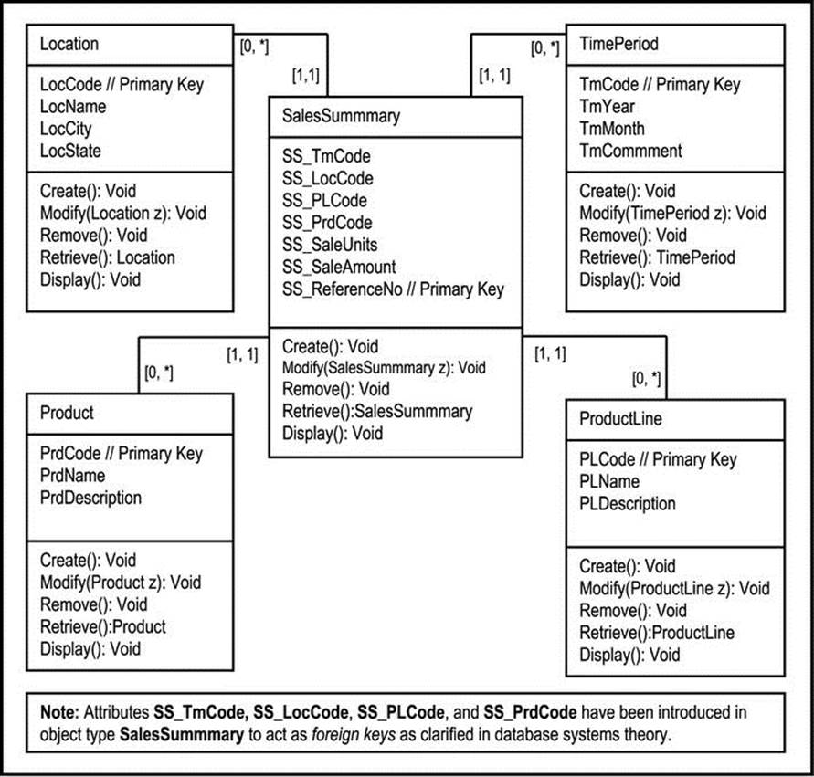
Figure A5-6. ORD for Tracking Sales Summary for a Large Marketing Company
![]() Note Since ORD can grow bulky rather quickly, it is common practice to deemphasize (or even sometimes omit) the details relating to attributes and operations on the ORD. Some tools provide a plus sign (+) to expand a related section of the diagram, or a minus sign (-) to contract a related section.
Note Since ORD can grow bulky rather quickly, it is common practice to deemphasize (or even sometimes omit) the details relating to attributes and operations on the ORD. Some tools provide a plus sign (+) to expand a related section of the diagram, or a minus sign (-) to contract a related section.
A5.5.2 CRC Card
The CRC card can also be very useful in providing details about a class (which is the implementation of an object type). For the purpose of comparison, Figure A5-7 summarizes the information contained in an OSD as well as a CRC card.
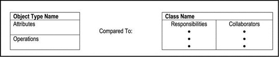
Figure A5-7. Object Structure Diagram versus the CRC Card
Traditionally, CRC cards were used manually to assist in the analysis of the software system. Designers would literally prepare a deck of CRC cards for the object types comprising the system (one CRC card per object type), and use them during brainstorming sessions to assist in refining and finalizing the structure and role of each object type of the system (review section A4.1.9). To bring this technique to a contemporary scenario, the CRC card can be easily stored electronically, and used in not only refining but also modeling the software system.
A5.6 Avoiding Multiple Inheritance Relationships
Dealing with multiple inheritances can be a challenge. You will recall from your OO programming, that they can cause confusion. Because of this, some OO programming languages (OOPLs) do not support them. James Rumbaugh in [Rumbaugh, 1991] describes three techniques for circumventing multiple inheritances; they are paraphrased here. The techniques (called workarounds) allow for avoidance of multiple inheritances in one of three ways:
· Delegation using aggregation
· Delegation and inheritance
· Nested generalization
A fourth approach for circumventing multiple inheritances is the use of interfaces as described in appendix 2. This approach is supported quite nicely in the Java programming language.
Figure A5-8 illustrates a multiple inheritances problem to be addressed. Let us examine how this can be resolved using the above-mentioned approaches, and as described in [Rumbaugh, 1991]. The first thing to note is that based on the figure, any alternate configuration should facilitate at least five categories of employees: tenured faculty, tenure track faculty, tenure track contractor, salaried contractor (no tenure track), and hourly paid staff. Now let us examine Rumbaugh’s workarounds.
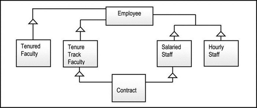
Figure A5-8. A Multiple Inheritance Problem
A5.6.1 Delegation Using Aggregation
The delegation via aggregation technique involves the introduction of abstract object types that are composed of other types. Figure A5-9 illustrates a solution to the multiple inheritance problem of Figure A5-8, using aggregation. Notice the splitting of Salaried Staff into two separate object types, namely Staff and Salaried. This is necessary since there could be salaried or hourly-paid staff members. The abstract object types introduced are Faculty and Staff. A quick visual examination will also reveal that the minimum five categories of employees are facilitated in the figure.
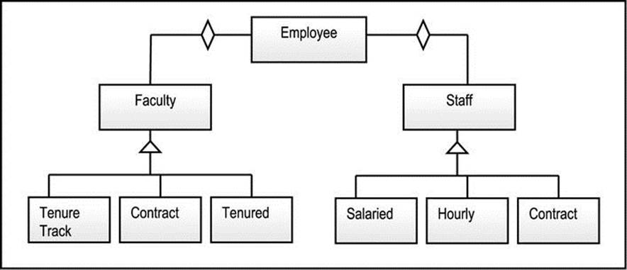
Figure A5-9. Multiple Inheritances using Delegation
![]() Note The introduced abstract object type needn’t have actual data attributes, and may merely consist of abstract operations (methods), which are overridden in the respective subtypes. This is particularly advantageous if you are using a purely object-oriented implementation language such as Java. This is the preferred approach for dealing with multiple inheritances.
Note The introduced abstract object type needn’t have actual data attributes, and may merely consist of abstract operations (methods), which are overridden in the respective subtypes. This is particularly advantageous if you are using a purely object-oriented implementation language such as Java. This is the preferred approach for dealing with multiple inheritances.
A5.6.2 Delegation and Inheritance
In the delegation and inheritance technique, we inherit the most important class and delegate the rest. Figure A5-10 illustrates a solution to the multiple inheritance problem of Figure A5-8, using this approach. The original problem did not indicate which class is the most important, a judgment call was made to inherit on the faculty side, and delegate on the staff side. With this approach, you must be prepared to make such judgments. The role of the abstract class Staff is identical to the explanation in the previous subsection. Also note that the minimum five categories of employees are again facilitated.
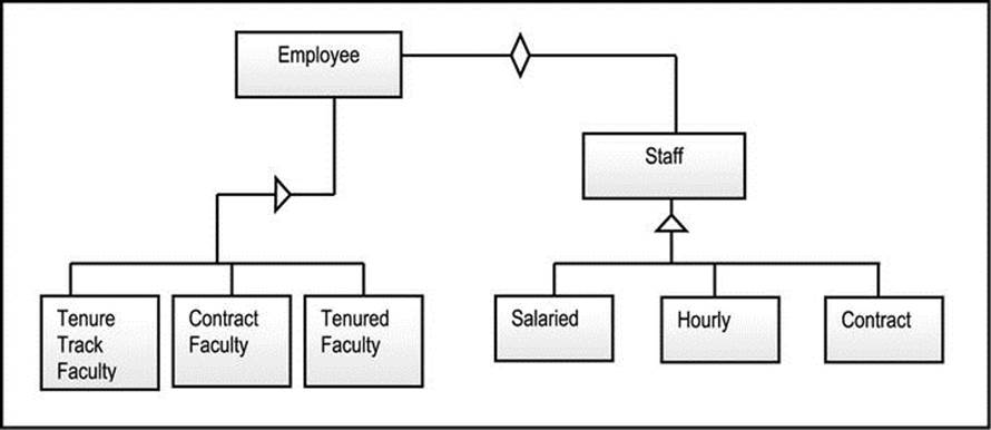
Figure A5-10. Multiple Inheritances via Inheritance and Delegation
A5.6.3 Nested generalization
The nested generalizations technique involves factoring one generalization first, then the other, until all possibilities are covered. It involves the introduction of abstract classes where necessary, in order to facilitate useful generalizations. Figure A5-11 illustrates a solution to the multiple inheritance problem of Figure A5-8, using nested generalization. Notice the introduction of three abstract object types, namely Faculty, Contract, and Staff. Also observe that as in the two previous approaches, the minimum five categories of employees are facilitated.
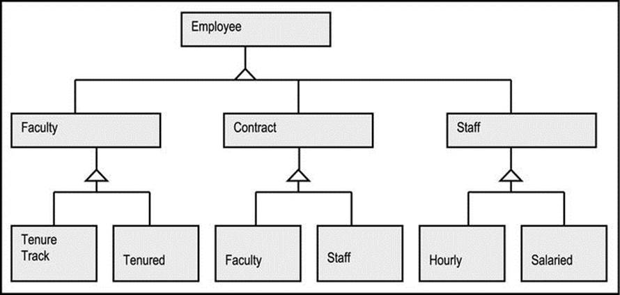
Figure A5-11. Multiple Inheritances via Nested Generalization
While this approach is very straightforward, it is not always recommended, since it often violates the principle of Occam’s Razor by significantly increasing the number of classes to be managed.
A5.7 Top-Down versus Bottom-Up
You may conduct your object categorization by using either a top-down approach, or a bottom-up approach. In practice, it is a good habit to use both approaches — one as a check-and-balance mechanism to the other. Invariably, your implementation will be bottom-up (you have to create classes before you can use them).
A5.7.1 Top-Down Approach
For the top-down approach, use the following guidelines:
1. Start by looking at a summarized picture: determine what are the main facets of information are to be managed.
2. Break down the facets into constituents and sub-constituents as necessary (avoiding unnecessary indentation levels).
3. Consider the facets as system modules or sub-systems, depending on the size of your project. Then consider the constituents and sub-constituents as object types.
4. A final step — not required for your ITC, but required for your database specification — is to identify and define for each object type, a set of properties (data attributes and allowable operations).
A5.7.2 Bottom-Up Approach
For the bottom-up approach, use the following guidelines:
1. Start out by identifying object types (tangible as well as intangible ones).
2. Identify and define for each object type, a set of properties (data attributes and allowable operations).
3. For each object type, provide an appropriate descriptive name.
4. Organize related object types into logical groups. These groups will constitute your super-types, system modules and/or subsystems (depending on the complexity of the project).
5. Integrate all modules and/or subsystems into one integrated system.
A5.8 Summary and Concluding Remarks
Here is a summary of what has been discussed in this chapter:
· The first step in object categorization is to identify the relationships that exist among object types. The different types of relationships are 1:1, 1:M, M:1, M:M, subtype-super-type, aggregation, and component relationships.
· Once the relationships have been identified, they should be incorporated in the model of the software system. This can be done via diagramming techniques such as fern diagrams, ORDs, and ITCs.
· Details about object types can be modeled via techniques such as OSDs, CRC cards, and O/ESGs.
· Depending on the software development tool at your disposal, it may be advisable to avoid multiple inheritances in your design, since they could pose problems during software development. This can be done via any of four strategies: delegation using aggregation, delegation and inheritance, nested generalizations, and interfaces.
· It is a good habit to employ both top-down and bottom-up approaches to balance each other, as you design the software system.
Having addressed the structure and interrelationships of object types making up the software system, our next task is to design the behavior of objects in the system. The next chapter will address this.
A5.9 References and/or Recommended Reading
[Foster, 2010] Foster, Elvis C. with Shripad V. Godbole. Database Systems: A Pragmatic Approach. Bloomington, IN: Xlibris Publishing, 2010. See chapters 3 – 5.
[Hoffer, 2007] Hoffer, Jeffrey A., Mary B. Prescott and Fred R. McFadden. Modern Database Management 8th ed. Upper Saddle River, NJ: Prentice Hall, 2007. See chapter 11.
[Lee, 2002] Lee, Richard C. and William M. Tepfenhart. Practical Object-Oriented Development With UML and Java. Upper Saddle River, NJ: Prentice Hall, 2002. See chapter 8.
[Martin, 1993] Martin, James and James Odell. Principles of Object Oriented Analysis and Design.Eaglewood Cliffs, New Jersey: Pretence Hall, 1993. See chapters 6 and 7.
[Rumbaugh, 1991] Rumbaugh, James, et. al. Object Oriented Modeling And Design. Eaglewood Cliffs, New Jersey: Pretence Hall, 1991. See chapter 4.