Computer Organization and Design (2016)
APPENDIX E
A Survey of RISC Architectures for Desktop, Server, and Embedded Computers
Steven Przybylskic, A Designer of the Stanford MIPS
Abstract
This appendix covers two groups of reduced instruction set computer (RISC) architectures: desktop and server RISCs, and embedded RISCs.
Keywords
addressing mode, instruction format, MIPS, MIPS core subset, multimedia extension, RISC, MIPS-64, Digital Alpha, SPARC v.9, PowerPC, Hewlett-Packard PA-RISC 2.0, ARM, Thumb, SuperH, M32R, MIPS-16, IBM, Motorola, Sun Microsystems, Hitachi, Mitsubishi, Advanced RISC Machines
RISC: any computer announced after 1985.
E.1 Introduction
E.2 Addressing Modes and Instruction Formats
E.3 Instructions: The MIPS Core Subset
E.4 Instructions: Multimedia Extensions of the Desktop/Server RISCs
E.5 Instructions: Digital Signal-Processing Extensions of the Embedded RISCs
E.6 Instructions: Common Extensions to MIPS Core
E.7 Instructions Unique to MIPS-64
E.8 Instructions Unique to Alpha
E.9 Instructions Unique to SPARC v9
E.10 Instructions Unique to PowerPC
E.11 Instructions Unique to PA-RISC 2.0
E.12 Instructions Unique to ARM
E.13 Instructions Unique to Thumb
E.14 Instructions Unique to SuperH
E.15 Instructions Unique to M32R
E.16 Instructions Unique to MIPS-16
E.17 Concluding Remarks
E.1 Introduction
We cover two groups of reduced instruction set computer (RISC) architectures in this appendix. The first group is the desktop and server RISCs:
■ Digital Alpha
■ Hewlett-Packard PA-RISC
■ IBM and Motorola PowerPC
■ MIPS INC MIPS-64
■ Sun Microsystems SPARC
The second group is the embedded RISCs:
■ Advanced RISC Machines ARM
■ Advanced RISC Machines Thumb
■ Hitachi SuperH
■ Mitsubishi M32R
■ MIPS INC MIPS-16
There has never been another class of computers so similar. This similarity allows the presentation of 10 architectures in about 50 pages. Characteristics of the desktop and server RISCs are found in Figure E.1.1 and the embedded RISCs in Figure E.1.2.
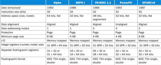
FIGURE E.1.1 Summary of the first version of five architectures for desktops and servers.
Except for the number of data address modes and some instruction set details, the integer instruction sets of these architectures are very similar. Contrast this with Figure E.17.1. Later versions of these architectures all support a flat, 64-bit address space.
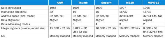
FIGURE E.1.2 Summary of five architectures for embedded applications.
Except for number of data address modes and some instruction set details, the integer instruction sets of these architectures are similar. Contrast this with Figure E.17.1.
Notice that the embedded RISCs tend to have 8 to 16 general-purpose registers while the desktop/server RISCs have 32, and that the length of instructions is 16 to 32 bits in embedded RISCs but always 32 bits in desktop/server RISCs.
Although shown as separate embedded instruction set architectures, Thumb and MIPS-16 are really optional modes of ARM and MIPS invoked by call instructions. When in this mode, they execute a subset of the native architecture using 16-bit-long instructions. These 16-bit instruction sets are not intended to be full architectures, but they are enough to encode most procedures. Both machines expect procedures to be homogeneous, with all instructions in either 16-bit mode or 32-bit mode. Programs will consist of procedures in 16-bit mode for density or in 32-bit mode for performance.
One complication of this description is that some of the older RISCs have been extended over the years. We have decided to describe the latest versions, of the architectures: MIPS-64, Alpha version 3, PA-RISC 2.0, and SPARC version 9 for the desktop/server; ARM version 4, Thumb version 1, Hitachi SuperH SH-3, M32R version 1, and MIPS-16 version 1 for the embedded ones.
The remaining sections proceed as follows: after discussing the addressing modes and instruction formats of our RISC architectures, we present the survey of the instructions in five steps:
■ Instructions found in the MIPS core, which is defined in Chapters 2 and 3 of the main text
■ Multimedia extensions of the desktop/server RISCs
■ Digital signal-processing extensions of the embedded RISCs
■ Instructions not found in the MIPS core but found in two or more architectures
■ The unique instructions and characteristics of each of the ten architectures
We give the evolution of the instruction sets in the final section and conclude with a speculation about future directions for RISCs.
E.2 Addressing Modes and Instruction Formats
Figure E.2.1 shows the data addressing modes supported by the desktop architectures. Since all have one register that always has the value 0 when used in address modes, the absolute address mode with limited range can be synthesized using zero as the base in displacement addressing. (This register can be changed by ALU operations in PowerPC; it is always 0 in the other machines.) Similarly, register indirect addressing is synthesized by using displacement addressing with an offset of 0. Simplified addressing modes is one distinguishing feature of RISC architectures.
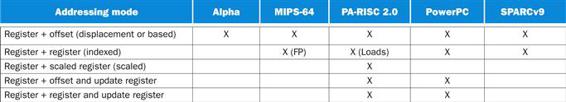
FIGURE E.2.1 Summary of data addressing modes supported by the desktop architectures.
PA RISC also has short address versions of the offset addressing modes. MIPS-64 has indexed addressing for floating-point loads and stores. (These addressing modes are described in Figure 2.18.)
Figure E.2.2 shows the data addressing modes supported by the embedded architectures. Unlike the desktop RISCs, these embedded machines do not reserve a register to contain 0. Although most have two to three simple addressing modes, ARM and SuperH have several, including fairly complex calculations. ARM has an addressing mode that can shift one register by any amount, add it to the other registers to form the address, and then update one register with this new address.
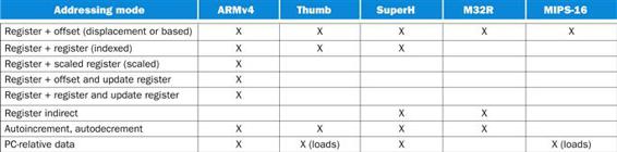
FIGURE E.2.2 Summary of data addressing modes supported by the embedded architectures.
SuperH and M32R have separate register indirect and register + offset addressing modes rather than just putting 0 in the off set of the latter mode. This increases the use of 16-bit instructions in the M32R, and it gives a wider set of address modes to different data transfer instructions in SuperH. To get greater addressing range, ARM and Thumb shift the offset left one or two bits if the data size is halfword or word. (These addressing modes are described in Figure 2.18.)
References to code are normally PC-relative, although jump register indirect is supported for returning from procedures, for case statements, and for pointer function calls. One variation is that PC-relative branch addresses are shifted left two bits before being added to the PC for the desktop RISCs, thereby increasing the branch distance. This works because the length of all instructions for the desktop RISCs is 32 bits, and instructions must be aligned on 32-bit words in memory. Embedded architectures with 16-bit-long instructions usually shift the PC-relative address by 1 for similar reasons.
Figure E.2.3 shows the format of the desktop RISC instructions, which include the size of the address. Each instruction set architecture uses these four primary instruction formats. Figure E.2.4 shows the six formats for the embedded RISC machines. The desire to have smaller code size via 16-bit instructions leads to more instruction formats.
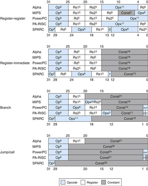
FIGURE E.2.3 Instruction formats for desktop/server RISC architectures.
These four formats are found in all five architectures. (The superscrift notation in this figure means the width of a field in bits.) Although the register fields are located in similar pieces of the instruction, be aware that the destination and two source fields are scrambled. Op=the main opcode, Opx=an opcode extension, Rd=the destination register, Rs1=source register 1, Rs2=source register 2, and Const=a constant (used as an immediate or as an address). Unlike the other RISCs, Alpha has a format for immediates in arithmetic and logical operations that is different from the data transfer format shown here. It provides an 8-bit immediate in bits 20 to 13 of the RR format, with bits 12 to 5 remaining as an opcode extension.
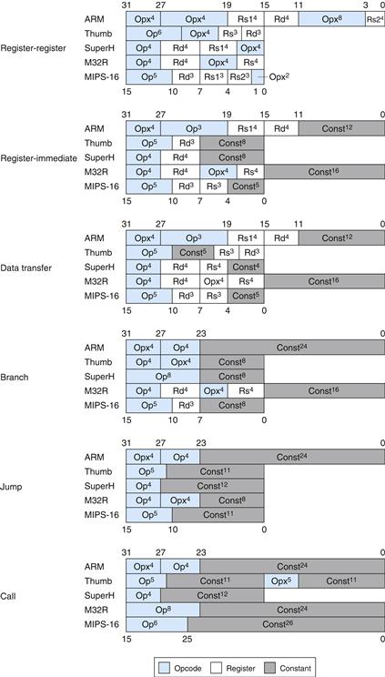
FIGURE E.2.4 Instruction formats for embedded RISC architectures.
These six formats are found in all five architectures. The notation is the same as in Figure E.2.3. Note the similarities in branch, jump, and call formats, and the diversity in register-register, register-immediate, and data transfer formats. The differences result from whether the architecture has 8 or 16 registers, whether it is a 2-or 3-operandformat, and whether the instruction length is 16 or 32 bits.
Figures E.2.5 and E.2.6 show the variations in extending constant fields to the full width of the registers. In this subtle point, the RISCs are similar but not identical.
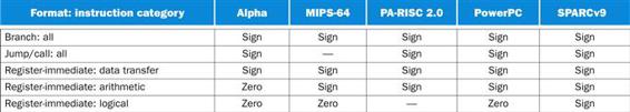
FIGURE E.2.5 Summary of constant extension for desktop RISCs.
The constants in the jump and call instructions of MIPS are not sign-extended, since they only replace the lower 28 bits of PC, leaving the upper 4 bits unchanged. PA-RISC has no logical immediate instructions.
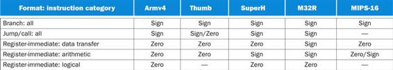
FIGURE E.2.6 Summary of constant extension for embedded RISCs.
The 16-bit-length instructions have much shorter immediates than those of the desktop RISCs, typically only five to eight bits. Most embedded RISCs, however, have a way to get a long address for procedure calls from two sequencial halfwords. The constants in the jump and call instructions of MIPS are not sign-extended, since they only replace the lower 28 bits of the PC, leaving the upper 4 bits unchanged. The 8-bit immediates in ARM can be rotated right an even number of bits between 2 and 30, yielding a large range of immediate values. For example, all powers of two are immediates in ARM.
E.3 Instructions: the MIPS Core Subset
The similarities of each architecture allow simultaneous descriptions, starting with the operations equivalent to the MIPS core.
MIPS Core Instructions
Almost every instruction found in the MIPS core is found in the other architectures, as Figures E.3.1 through E.3.5 show. (For reference, definitions of the MIPS instructions are found in the MIPS Reference Data Card at the beginning of the book.) Instructions are listed under four categories: data transfer (Figure E.3.1); arithmetic/logical (Figure E.3.2); control (Figure E.3.3); and floating point (Figure E.3.4). A fifth category (Figure E.3.5) shows conventions for register usage and pseudoinstructions on each architecture. If a MIPS core instruction requires a short sequence of instructions in other architectures, these instructions are separated by semicolons in Figures E.3.1 through E.3.5. (To avoid confusion, the destination register will always be the leftmost operand in this appendix, independent of the notation normally used with each architecture.) Figures E.3.6 through E.3.9 show the equivalent listing for embedded RISCs. Note that floating point is generally not defined for the embedded RISCs.
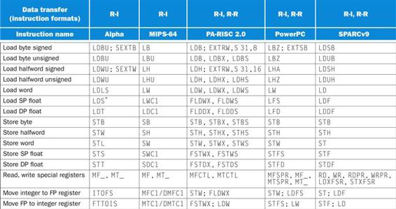
FIGURE E.3.1 Desktop RISC data transfer instructions equivalent to MIPS core.
A sequence of instructions to synthesize a MIPS instruction is shown separated by semicolons. If there are several choices of instructions equivalent to MIPS core, they are separated by commas. For this figure, halfword is 16 bits and word is 32 bits. Note that in Alpha, LDS converts single precision floating point to double precision and loads the entire 64-bit register.
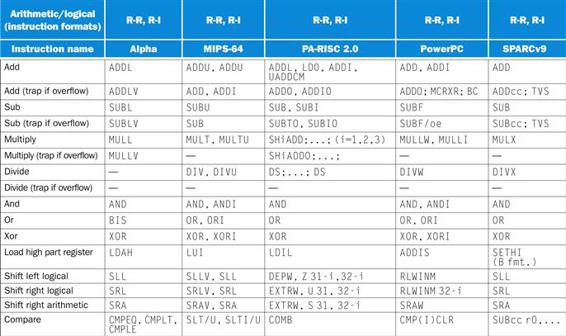
FIGURE E.3.2 Desktop RISC arithmetic/logical instructions equivalent to MIPS core.
Dashes mean the operation is not available in that architecture, or not synthesized in a few instructions. Such a sequence of instructions is shown separated by semicolons. If there are several choices of instructions equivalent to MIPS core, they are separated by commas. Note that in the “Arithmetic/logical” category, all machines but SPARC use separate instruction mnemonics to indicate an immediate operand; SPARC offers immediate versions of these instructions but uses a single mnemonic. (Of course these are separate opcodes!)
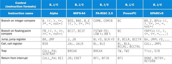
FIGURE E.3.3 Desktop RISC control instructions equivalent to MIPS core.
If there are several choices of instructions equivalent to MIPS core, they are separated by commas.
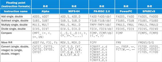
FIGURE E.3.4 Desktop RISC floating-point instructions equivalent to MIPS core.
Dashes mean the operation is not available in that architecture, or not synthesized in a few instructions. If there are several choices of instructions equivalent to MIPS core, they are separated by commas.
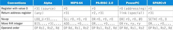
FIGURE E.3.5 Conventions of desktop RISC architectures equivalent to MIPS core.
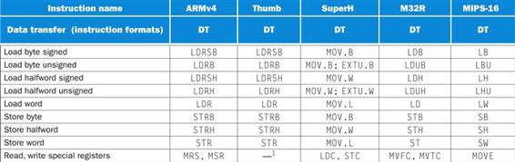
FIGURE E.3.6 Embedded RISC data transfer instructions equivalent to MIPS core.
A sequence of instructions to synthesize a MIPS instruction is shown separated by semicolons. Note that floating point is generally not defined for the embedded RISCs. Thumb and MIPS-16 are just 16-bit instruction subsets of the ARM and MIPS architectures, so machines can switch modes and execute the full instruction set. We use —1 to show sequences that are available in 32-bit mode but not 16-bit mode in Thumb or MIPS-16.
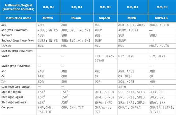
FIGURE E.3.7 Embedded RISC arithmetic/logical instructions equivalent to MIPS core.
Dashes mean the operation is not available in that architecture, or not synthesized in a few instructions. Such a sequence of instructions is shown separated by semicolons. If there are several choices of instructions equivalent to MIPS core, they are separated by commas. Thumb and MIPS-16 are just 16-bit instruction subsets of the ARM and MIPS architectures, so machines can switch modes and execute the full instruction set. We use —1 to show sequences that are available in 32-bit mode but not 16-bit mode in Thumb or MIPS-16. The superscript 2 shows new instructions found only in 16-bit mode of Thumb or MIPS-16, such as CMP/I2. ARM includes shifts as part of every data operation instruction, so the shifts with superscript 3 are just a variation of a move instruction, such as LSR3.
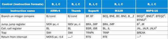
FIGURE E.3.8 Embedded RISC control instructions equivalent to MIPS core.
Thumb and MIPS-16 are just 16-bit instruction subsets of the ARM and MIPS architectures, so machines can switch modes and execute the full instruction set. We use —1 to show sequences that are available in 32-bit mode but not 16-bit mode in Thumb or MIPS-16. The superscript 2 shows new instructions found only in 16-bit mode of Thumb or MIPS-16, such as BTEQZ2.
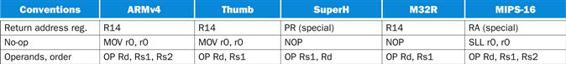
FIGURE E.3.9 Conventions of embedded RISC instructions equivalent to MIPS core.
Every architecture must have a scheme for compare and conditional branch, but despite all the similarities, each of these architectures has found a different way to perform the operation.
Compare and Conditional Branch
SPARC uses the traditional four condition code bits stored in the program status word: negative, zero, carry, and overflow. They can be set on any arithmetic or logical instruction; unlike earlier architectures, this setting is optional on each instruction. An explicit option leads to fewer problems in pipelined implementation. Although condition codes can be set as a side effect of an operation, explicit com pares are synthesized with a subtract using r0 as the destination. SPARC conditional branches test condition codes to determine all possible unsigned and signed relations. Floating point uses separate condition codes to encode the IEEE 754 conditions, requiring a floating-point compare instruction. Version 9 expanded SPARC branches in four ways: a separate set of condition codes for 64-bit operations; a branch that tests the contents of a register and branches if the value is =, not=, <, <=, >=, or <= 0 (see MIPS below); three more sets of floating-point condition codes; and branch instructions that encode static branch prediction.
PowerPC also uses four condition codes—less than, greater than, equal, and summary overflow—but it has eight copies of them. This redundancy allows the PowerPC instructions to use different condition codes without conflict, essentially giving PowerPC eight extra 4-bit registers. Any of these eight condition codes can be the target of a compare instruction, and any can be the source of a conditional branch. The integer instructions have an option bit that behaves as if the integer op is followed by a compare to zero that sets the first condition “register.” PowerPC also lets the second “register” be optionally set by floating-point instructions. PowerPC provides logical operations among these eight 4-bit condition code registers (CRAND, CROR, CRXOR, CRNAND, CRNOR, CREQV), allowing more complex conditions to be tested by a single branch.
MIPS uses the contents of registers to evaluate conditional branches. Any two registers can be compared for equality (BEQ) or inequality (BNE), and then the branch is taken if the condition holds. The set on less than instructions (SLT, SLTI, SLTU, SLTIU) compare two operands and then set the destination register to 1 if less and to 0 otherwise. These instructions are enough to synthesize the full set of relations. Because of the popularity of comparisons to 0, MIPS includes special compare and branch instructions for all such comparisons: greater than or equal to zero (BGEZ), greater than zero (BGTZ), less than or equal to zero (BLEZ), and less than zero (BLTZ). Of course, equal and not equal to zero can be synthe sized using r0 with BEQ and BNE. Like SPARC, MIPS I uses a condition code for floating point with separate floating-point compare and branch instructions; MIPS IV expanded this to eight floating-point condition codes, with the floating point comparisons and branch instructions specifying the condition to set or test.
Alpha compares (CMPEQ, CMPLT, CMPLE, CMPULT, CMPULE) test two registers and set a third to 1 if the condition is true and to 0 otherwise. Floating-point compares (CMTEQ, CMTLT, CMTLE, CMTUN) set the result to 2.0 if the condition holds and to 0 other wise. The branch instructions compare one register to 0 (BEQ, BGE, BGT, BLE, BLT, BNE) or its least significant bit to 0 (BLBC, BLBS) and then branch if the condition holds.
PA-RISC has many branch options, which we’ll see in Section E.8. The most straightforward is a compare and branch instruction (COMB), which compares two registers, branches depending on the standard relations, and then tests the least significant bit of the result of the comparison.
ARM is similar to SPARC, in that it provides four traditional condition codes that are optionally set. CMP subtracts one oper and from the other and the differ ence sets the condition codes. Compare negative (CMN) adds one operand to the other, and the sum sets the condition codes. TST performs logical AND on the two operands to set all condition codes but overflow, while TEQ uses exclusive OR to set the first three condition codes. Like SPARC, the conditional version of the ARM branch instruction tests condition codes to determine all possible unsigned and signed relations.
As we shall see in Section E.9, one unusual feature of ARM is that every instruction has the option of executing conditionally depending on the condition codes. (This bears similarities to the annulling option of PA-RISC, seen in Section E.8.)
Not surprisingly, Thumb follows ARM. The differences are that setting condition codes are not optional, the TEQ instruction is dropped, and there is no conditional execution of instructions.
The Hitachi SuperH uses a single T-bit condition that is set by compare instructions. Two branch instructions decide to branch if either the T bit is 1 (BT) or the T bit is 0 (BF). The two flavors of branches allow fewer comparison instructions.
Mitsubishi M32R also offers a single condition code bit (C) used for signed and unsigned comparisons (CMP, CMPI, CMPU, CMPUI) to see if one register is less than the other or not, similar to the MIPS set on less than instructions. Two branch instructions test to see if the C bit is 1 or 0: BC and BNC. The M32R also includes instructions to branch on equality or inequality of registers (BEQ and BNE) and all relations of a register to 0 (BGEZ, BGTZ, BLEZ, BLTZ, BEQZ, BNEZ). Unlike BC and BNC, these last instructions are all 32 bits wide.
MIPS-16 keeps set on less than instructions (SLT, SLTI, SLTU, SLTIU), but instead of putting the result in one of the eight registers, it is placed in a special register named T. MIPS-16 is always implemented in machines that also have the full 32-bit MIPS instructions and registers; hence, register T is really register 24 in the full MIPS architecture. The MIPS-16 branch instructions test to see if a register is or is not equal to zero (BEQZ and BNEZ). There are also instructions that branch if register T is or is not equal to zero (BTEQZ and BTNEZ). To test if two registers are equal, MIPS added compare instructions (CMP, CMPI) that compute the exclusive OR of two registers and place the result in register T. Compare was added since MIPS-16 left out instructions to compare and branch if registers are equal or not (BEQ and BNE).
Figures E.3.10 and E.3.11 summarize the schemes used for conditional branches.
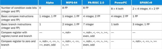
FIGURE E.3.10 Summary of five desktop RISC approaches to conditional branches.
Floating-point branch on PA-RISC is accomplished by copying the FP status register into an integer register and then using the branch on bit instruction to test the FP comparison bit. Integer compare on SPARC is synthesized with an arithmetic instruction that sets the condition codes using r0 as the destination.
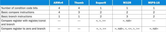
FIGURE E.3.11 Summary of five embedded RISC approaches to conditional branches
E.4 Instructions: Multimedia Extensions of the Desktop/Server RISCs
Since every desktop microprocessor by definition has its own graphical displays, as transistor budgets increased it was inevitable that support would be added for graphics operations. Many graphics systems use eight bits to represent each of the three primary colors plus eight bits for the location of a pixel.
The addition of speakers and microphones for teleconferencing and video games suggested support of sound as well. Audio samples need more than eight bits of precision, but 16 bits are sufficient.
Every microprocessor has special support so that bytes and halfwords take up less space when stored in memory, but due to the infrequency of arithmetic operations on these data sizes in typical integer programs, there is little support beyond data transfers. The architects of the Intel i860, which was justified as a graphical accelerator within the company, recognized that many graphics and audio applications would perform the same operation on vectors of this data. Although a vector unit was beyond the transistor budget of the i860 in 1989, by partitioning the carry chains within a 64-bit ALU, it could perform simultaneous operations on short vectors of eight 8-bit oper ands, four 16-bit operands, or two 32-bit operands. The cost of such partitioned ALUs was small. Applications that lend themselves to such support include MPEG (video), games like DOOM (3-D graphics), Adobe Photoshop (digital photography), and teleconferencing (audio and image processing).
Like a virus, over time such multimedia support has spread to nearly every desktop microprocessor. HP was the first successful desktop RISC to include such support. As we shall see, this virus spread unevenly. The PowerPC is the only holdout, and rumors are that it is “running a fever.”
These extensions have been called subword parallelism, vector, or SIMD (single-instruction, multiple data) (see Chapter 6). Since Intel marketing uses SIMD to describe the MMX extension of the 8086, that has become the popular name. Figure E.4.1 summarizes the support by architecture.
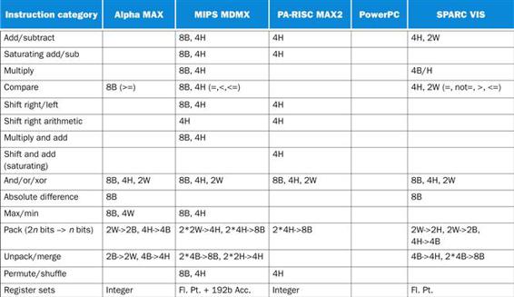
FIGURE E.4.1 Summary of multimedia support for desktop RISCs.
B stands for byte (8 bits), H for half word (16 bits), and W for word (32 bits). Thus 8B means an operation on eight bytes in a single instruction. Pack and unpack use the notation 2*2W to mean two operands each with two words. Note that MDMX has vector/scalar operations, where the scalar is specified as an element of one of the vector registers. This table is a simplification of the full multimedia architectures, leaving out many details. For example, MIPS MDMX includes instructions to multiplex between two operands, HP MAX2 includes an instruction to calculate averages, and SPARC VIS includes instructions to set registers to constants. Also, this table does not include the memory alignment operation of MDMX, MAX, and VIS.
From Figure E.4.1, you can see that in general MIPS MDMX works on eight bytes or four halfwords per instruction, HP PA-RISC MAX2 works on four halfwords, SPARC VIS works on four halfwords or two words, and Alpha doesn’t do much. The Alpha MAX operations are just byte versions of compare, min, max, and absolute difference, leaving it up to software to isolate fields and perform parallel adds, subtracts, and multiplies on bytes and halfwords. MIPS also added operations to work on two 32-bit floating-point operands per cycle, but they are considered part of MIPS V and not simply multimedia extensions (see Section E.7).
One feature not generally found in general-purpose microprocessors is saturating operations. Saturation means that when a calculation overflows, the result is set to the largest positive number or most negative number, rather than a modulo calculation as in two’s complement arithmetic. Commonly found in digital signal processors (see the next section), these saturating operations are helpful in routines for filtering.
These machines largely used existing register sets to hold operands: integer registers for Alpha and HP PA-RISC and floating-point registers for MIPS and Sun. Hence data transfers are accomplished with standard load and store instructions. MIPS also added a 192-bit (3*64) wide register to act as an accumulator for some operations. By having three times the native data width, it can be partitioned to accumulate either eight bytes with 24 bits per field or four halfwords with 48 bits per field. This wide accumulator can be used for add, subtract, and multiply/add instructions. MIPS claims performance advantages of two to four times for the accumulator.
Perhaps the surprising conclusion of this table is the lack of consistency. The only operations found on all four are the logical operations (AND, OR, XOR), which do not need a partitioned ALU. If we leave out the frugal Alpha, then the only other common operations are parallel adds and subtracts on four halfwords.
Each manufacturer states that these are instructions intended to be used in hand-optimized subroutine libraries, an intention likely to be followed, as a compiler that works well with multimedia extensions of all desktop RISCs would be challenging.
E.5 Instructions: Digital Signal-Processing Extensions of the Embedded RISCs
One feature found in every digital signal processor (DSP) architecture is support for integer multiply-accumulate. The multi plies tend to be on shorter words than regular integers, such as 16 bits, and the accumulator tends to be on longer words, such as 64 bits. The reason for multiply-accumulate is to efficiently implement digital filters, common in DSP applications. Since Thumb and MIPS-16 are subset architectures, they do not provide such support. Instead, programmers should use the DSP or multimedia extensions found in the 32-bit mode instructions of ARM and MIPS-64.
Figure E.5.1 shows the size of the multiply, the size of the accumulator, and the operations and instruction names for the embedded RISCs. Machines with accumulator sizes greater than 32 and less than 64 bits will force the upper bits to remain as the sign bits, thereby “saturating” the add to set to maximum and minimum fixed-point values if the operations overflow.
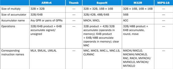
FIGURE E.5.1 Summary of five embedded RISC approaches to multiply-accumulate.
E.6 Instructions: Common Extensions to MIPS Core
Figures E.6.1 through E.6.7 list instructions not found in Figures E.3.5 through E.3.11 in the same four categories. Instructions are put in these lists if they appear in more than one of the standard architectures. The instructions are defined using the hardware description language defined in Figure E.6.8.

FIGURE E.6.1 Data transfer instructions not found in MIPS core but found in two or more of the five desktop architectures.
The load linked/store conditional pair of instructions gives Alpha and MIPS atomic operations for semaphores, allowing data to be read from memory, modified, and stored without fear of interrupts or other machines accessing the data in a multiprocessor (see Chapter 2). Prefetching in the Alpha to external caches is accomplished with FETCH and FETCH_M; on-chip cache prefetches use LD_Q A, R31, and LD_Y A. F31 is used in the Alpha 21164 (see Bhandarkar [1995], p. 190).
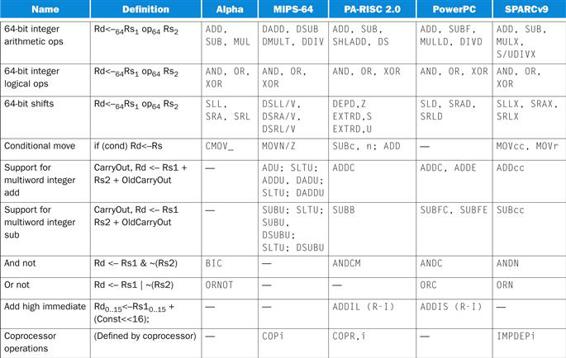
FIGURE E.6.2 Arithmetic/logical instructions not found in MIPS core but found in two or more of the five desktop architectures.
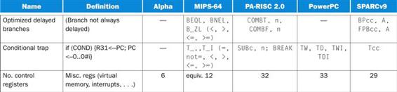
FIGURE E.6.3 Control instructions not found in MIPS core but found in two or more of the five desktop architectures.
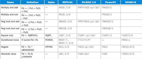
FIGURE E.6.4 Floating-point instructions not found in MIPS core but found in two or more of the five desktop architectures.
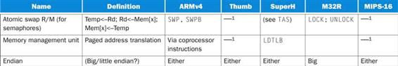
FIGURE E.6.5 Data transfer instructions not found in MIPS core but found in two or more of the five embedded architectures.
We use —1 to show sequences that are available in 32-bit mode but not 16-bit mode in Thumb or MIPS-16.
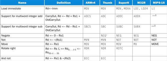
FIGURE E.6.6 Arithmetic/logical instructions not found in MIPS core but found in two or more of the five embedded architectures.
We use —1 to show sequences that are available in 32-bit mode but not in 16-bit mode in Thumb or MIPS-16. The superscript 2 shows new instructions found only in 16-bit mode of Thumb or MIPS-16, such as NEG2.
![]()
FIGURE E.6.7 Control information in the five embedded architectures.
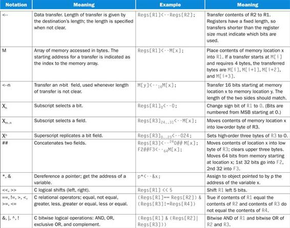
FIGURE E.6.8 Hardware description notation (and some standard C operators).
Although most of the categories are self-explanatory, a few bear comment:
■ The “atomic swap” row means a primitive that can exchange a register with memory without interruption. This is useful for operating system semaphores in a uniprocessor as well as for multiprocessor synchronization (see Section 2.11 in Chapter 2).
■ The 64-bit data transfer and operation rows show how MIPS, PowerPC, and SPARC define 64-bit addressing and integer operations. SPARC simply defines all register and addressing operations to be 64 bits, adding only special instructions for 64-bit shifts, data transfers, and branches. MIPS includes the same extensions, plus it adds separate 64-bit signed arithmetic instructions. PowerPC adds 64-bit right shift, load, store, divide, and compare and has a separate mode determining whether instructions are interpreted as 32-or 64-bit operations; 64-bit operations will not work in a machine that only supports 32-bit mode. PA-RISC is expanded to 64-bit addressing and operations in version 2.0.
■ The “prefetch” instruction supplies an address and hint to the implementation about the data. Hints include whether the data is likely to be read or written soon, likely to be read or written only once, or likely to be read or written many times. Prefetch does not cause exceptions. MIPS has a version that adds two registers to get the address for floating-point programs, unlike nonfloating-point MIPS programs.
■ In the “Endian” row, “Big/little” means there is a bit in the program status register that allows the processor to act either as big endian or little endian (see Appendix B). This can be accomplished by simply complementing some of the least significant bits of the address in data transfer instructions.
■ The “shared memory synchronization” helps with cache-coherent multi processors: all loads and stores executed before the instruction must complete before loads and stores after it can start. (See Chapter 2.)
■ The “coprocessor operations” row lists several categories that allow for the processor to be extended with special-purpose hardware.
One difference that needs a longer explanation is the optimized branches. Figure E.6.9 shows the options. The Alpha and PowerPC offer branches that take effect immediately, like branches on earlier architectures. To accelerate branches, these machines use branch prediction (see Chapter 4). All the rest of the desktop RISCs offer delayed branches (see Appendix A). The embedded RISCs generally do not support delayed branch, with the exception of SuperH, which has it as an option.
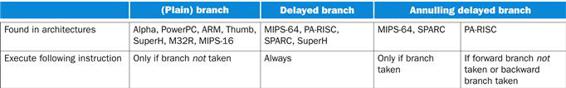
FIGURE E.6.9 When the instruction following the branch is executed for three types of branches.
The other three desktop RISCs provide a version of delayed branch that makes it easier to fill the delay slot. The SPARC “annulling” branch executes the instruction in the delay slot only if the branch is taken; otherwise the instruction is annulled. This means the instruction at the target of the branch can safely be copied into the delay slot, since it will only be executed if the branch is taken. The restrictions are that the target is not another branch and that the target is known at compile time. (SPARC also offers a nondelayed jump because an unconditional branch with the annul bit set does not execute the following instruction.) Later versions of the MIPS architecture have added a branch likely instruction that also annuls the following instruction if the branch is not taken. PA-RISC allows almost any instruction to annul the next instruction, including branches. Its “nullifying” branch option will execute the next instruction depending on the direction of the branch and whether it is taken (i.e., if a forward branch is not taken or a backward branch is taken). Presumably this choice was made to optimize loops, allowing the instructions following the exit branch and the looping branch to exe cute in the common case.
Now that we have covered the similarities, we will focus on the unique features of each architecture. We first cover the desktop/server RISCs, ordering them by length of description of the unique features from shortest to longest, and then the embedded RISCs.
E.7 Instructions Unique to MIPS-64
MIPS has gone through five generations of instruction sets, and this evolution has generally added features found in other architectures. Here are the salient unique features of MIPS, the first several of which were found in the original instruction set.
Nonaligned Data Transfers
MIPS has special instructions to handle misaligned words in memory. A rare event in most programs, it is included for supporting 16-bit minicomputer applications and for doing memcpy and strcpy faster. Although most RISCs trap if you try to load a word or store a word to a misaligned address, on all architectures misaligned words can be accessed without traps by using four load byte instructions and then assembling the result using shifts and logical ORs. The MIPS load and store word left and right instructions (LWL, LWR, SWL, SWR) allow this to be done in just two instructions: LWL loads the left portion of the register and LWR loads the right portion of the register. SWL and SWR do the corresponding stores. Figure E.7.1 shows how they work. There are also 64-bit versions of these instructions.
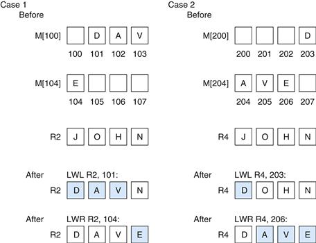
FIGURE E.7.1 MIPS instructions for unaligned word reads.
This figure assumes operation in big-endian mode. Case 1 first loads the three bytes 101, 102, and 103 into the left of R2, leaving the least significant byte undisturbed. The following LWR simply loads byte 104 into the least significant byte of R2, leaving the other bytes of the register unchanged using LWL. Case 2 first loads byte 203 into the most significant byte of R4, and the following LWR loads the other three bytes of R4 from memory bytes 204, 205, and 206. LWL reads the word with the first byte from memory, shifts to the left to discard the unneeded byte(s), and changes only those bytes in Rd. The byte(s) transferred are from the first byte to the lowest-order byte of the word. The following LWR addresses the last byte, right-shifts to discard the unneeded byte(s), and finally changes only those bytes of Rd. The byte(s) transferred are from the last byte up to the highest-order byte of the word. Store word left (SWL) is simply the inverse of LWL, and store word right (SWR) is the inverse of LWR. Changing to little-endian mode flips which bytes are selected and discarded. (If big-little, left-right, load-store seem confusing, don’t worry; they work!)
Remaining Instructions
Below is a list of the remaining unique details of the MIPS-64 architecture:
■ NOR—This logical instruction calculates ,(Rs1 | Rs2).
■ Constant shift amount—Nonvariable shifts use the 5-bit constant field shown in the register-register format in Figure E.2.3.
■ SYSCALL—This special trap instruction is used to invoke the operating system.
■ Move to/from control registers—CTCi and CFCi move between the integer registers and control registers.
■ Jump/call not PC-relative—The 26-bit address of jumps and calls is not added to the PC. It is shifted left two bits and replaces the lower 28 bits of the PC. This would only make a difference if the program were located near a 256 MB boundary.
■ TLB instructions—Translation-lookaside buffer (TLB) misses were handled in software in MIPS I, so the instruction set also had instructions for manipulating the registers of the TLB (see Chapter 5 for more on TLBs). These registers are considered part of the “system coprocessor.” Since MIPS I the instructions differ among versions of the architecture; they are more part of the implementations than part of the instruction set architecture.
■ Reciprocal and reciprocal square root—These instructions, which do not follow IEEE 754 guidelines of proper rounding, are included apparently for applications that value speed of divide and square root more than they value accuracy.
■ Conditional procedure call instructions—BGEZAL saves the return address and branches if the content of Rs1 is greater than or equal to zero, and BLTZAL does the same for less than zero. The purpose of these instructions is to get a PC-relative call. (There are “likely” versions of these instructions as well.)
■ Parallel single precision floating-point operations—As well as extending the architecture with parallel integer operations in MDMX, MIPS-64 also supports two parallel 32-bit floating-point operations on 64-bit registers in a single instruction. “Paired single” operations include add (ADD.P S), subtract (SUB.P S), compare (C.__. PS), convert (CVT.PS.S, CVT.S.PL, CVT.S.PU), negate (NEG.P S), absolute value (ABS.PS), move (MOV.PS, MOVF.PS, MOVT.PS), multiply (MUL.PS), multiply-add (MADD. PS), and multiply-subtract (MSUB. PS).
There is no specific provision in the MIPS architecture for floating-point execution to proceed in parallel with integer execution, but the MIPS implementations of floating point allow this to happen by checking to see if arithmetic interrupts are possible early in the cycle. Normally, exception detection would force serialization of execution of integer and floating-point operations.
E.8 Instructions Unique to Alpha
The Alpha was intended to be an architecture that made it easy to build high-performance implementations. Toward that goal, the architects originally made two controversial decisions: imprecise floating-point exceptions and no byte or halfword data transfers.
To simplify pipelined execution, Alpha does not require that an exception act as if no instructions past a certain point are executed and that all before that point have been executed. It sup plies the TRAPB instruction, which stalls until all prior arithmetic instructions are guaranteed to complete without incurring arithmetic exceptions. In the most conservative mode, placing one TRAPB per exception-causing instruction slows execution by roughly five times but provides precise exceptions (see Darcy and Gay [1996]).
Code that does not include TRAPB does not obey the IEEE 754 floating-point standard. The reason is that parts of the standard (NaNs, infinities, and denormals) are implemented in software on Alpha, as they are on many other microprocessors. To implement these operations in software, however, programs must find the offending instruction and operand values, which cannot be done with imprecise interrupts!
When the architecture was developed, it was believed by the architects that byte loads and stores would slow down data transfers. Byte loads require an extra shifter in the data transfer path, and byte stores require that the memory system per form a read-modify-write for memory systems with error correction codes, since the new ECC value must be recalculated. This omission meant that byte stores required the sequence load word, replaced the desired byte, and then stored the word. (Inconsistently, floating-point loads go through considerable byte swap ping to convert the obtuse VAX floating-point formats into a canonical form.)
To reduce the number of instructions to get the desired data, Alpha includes an elaborate set of byte manipulation instructions: extract field and zero rest of a register (EXTxx), insert field (INSxx), mask rest of a register (MSKxx), zero fields of a register (ZAP), and compare multiple bytes (CMPGE).
Apparently, the implementors were not as bothered by load and store byte as were the original architects. Beginning with the shrink of the second version of the Alpha chip (21164A), the architecture does include loads and stores for bytes and halfwords.
Remaining Instructions
Below is a list of the remaining unique instructions of the Alpha architecture:
■ PAL code—To provide the operations that the VAX performed in microcode, Alpha provides a mode that runs with all privileges enabled, interrupts disabled, and virtual memory mapping turned off for instructions. PAL (privileged architecture library) code is used for TLB management, atomic memory operations, and some operating system primitives. PAL code is called via the CALL_PAL instruction.
■ No divide—Integer divide is not supported in hardware.
■ “Unaligned” load-store—LDQ_U and STQ_U load and store 64-bit data using addresses that ignore the least significant three bits. Extract instructions then select the desired unaligned word using the lower address bits. These instruc -tions are similar to LWL/R, SWL/R in MIPS.
■ Floating-point single precision represented as double precision—Single precision data is kept as conventional 32-bit formats in memory but is converted to 64-bit double precision format in registers.
■ Floating-point register F31 is fixed at zero—To simplify comparisons to zero.
■ VAX floating-point formats—To maintain compatibility with the VAX architecture, in addition to the IEEE 754 single and double precision formats called S and T, Alpha supports the VAX single and double precision formats called F and G, but not VAX format D. (D had too narrow an exponent field to be useful for double precision and was replaced by G in VAX code.)
■ Bit count instructions—Version 3 of the architecture added instructions to count the number of leading zeros (CTLZ), count the number of trailing zeros (CTTZ), and count the number of ones in a word (CTPOP). Originally found on Cray computers, these instructions help with decryption.
E.9 Instructions Unique to SPARC v.9
Several features are unique to SPARC.
Register Windows
The primary unique feature of SPARC is register windows, an optimization for reducing register traffic on procedure calls. Several banks of registers are used, with a new one allocated on each procedure call. Although this could limit the depth of procedure calls, the limitation is avoided by operating the banks as a circular buffer, providing unlimited depth. The knee of the cost/performance curve seems to be six to eight banks.
SPARC can have between 2 and 32 windows, typically using 8 registers each for the globals, locals, incoming parameters, and outgoing parameters. (Given that each window has 16 unique registers, an implementation of SPARC can have as few as 40 physical registers and as many as 520, although most have 128 to 136, so far.) Rather than tie window changes with call and return instructions, SPARC has the separate instructions SAVE and RESTORE. SAVE is used to “save” the caller’s window by pointing to the next window of registers in addition to performing an add instruction. The trick is that the source registers are from the caller’s window of the addition operation, while the destination register is in the callee’s window. SPARC compilers typically use this instruction for changing the stack pointer to allocate local variables in a new stack frame. RESTORE is the inverse of SAVE, bringing back the caller’s window while acting as an add instruction, with the source registers from the callee’s window and the destination register in the caller’s window. This automatically deallocates the stack frame. Compilers can also make use of it for generating the callee’s final return value.
The danger of register windows is that the larger number of registers could slow down the clock rate. This was not the case for early implementations. The SPARC architecture (with register windows) and the MIPS R2000 architecture (without) have been built in several technologies since 1987. For several generations, the SPARC clock rate has not been slower than the MIPS clock rate for implementations in similar technologies, probably because cache access times dominate register access times in these implementations. The current-generation machines took different implementation strategies—in order versus out of order—and it’s unlikely that the number of registers by themselves determined the clock rate in either machine. Recently, other architectures have included register windows: Tensilica and IA-64.
Another data transfer feature is alternate space option for loads and stores. This simply allows the memory system to identify memory accesses to input/output devices, or to control registers for devices such as the cache and memory management unit.
Fast Traps
Version 9 SPARC includes support to make traps fast. It expands the single level of traps to at least four levels, allowing the window overflow and underflow trap handlers to be interrupted. The extra levels mean the handler does not need to check for page faults or misaligned stack pointers explicitly in the code, thereby making the handler faster. Two new instructions were added to return from this multilevel handler: RETRY (which retries the interrupted instruction) and DONE (which does not). To support user-level traps, the instruction RETURN will return from the trap in nonprivileged mode.
Support for LISP and Smalltalk
The primary remaining arithmetic feature is tagged addition and subtraction. The designers of SPARC spent some time thinking about languages like LISP and Smalltalk, and this influenced some of the features of SPARC already discussed: register windows, conditional trap instructions, calls with 32-bit instruction addresses, and multiword arithmetic (see Taylor, et al. [1986] and Ungar, et al. [1984]). A small amount of support is offered for tagged data types with operations for addition, subtraction, and, hence, comparison. The two least significant bits indicate whether the operand is an integer (coded as 00), so TADDcc and TSUBcc set the overflow bit if either operand is not tagged as an integer or if the result is too large. A subsequent conditional branch or trap instruction can decide what to do. (If the operands are not integers, software recovers the operands, checks the types of the operands, and invokes the correct operation based on those types.) It turns out that the misaligned memory access trap can also be put to use for tagged data, since loading from a pointer with the wrong tag can be an invalid access. Figure E.9.1 shows both types of tag support.
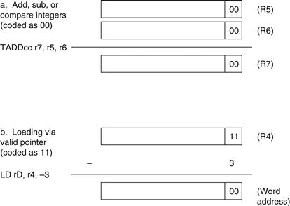
FIGURE E.9.1 SPARC uses the two least significant bits to encode different data types for the tagged arithmetic instructions.
a. Integer arithmetic takes a single cycle as long as the operands and the result are integers. b. The misaligned trap can be used to catch invalid memory accesses, such as trying to use an integer as a pointer. For languages with paired data like LISP, an off set of ×3 can be used to access the even word of a pair (CAR) and +1 can be used for the odd word of a pair (CDR).
Overlapped Integer and Floating-Point Operations
SPARC allows floating-point instructions to overlap execution with integer instructions. To recover from an interrupt during such a situation, SPARC has a queue of pending floating-point instructions and their addresses. RDPR allows the processor to empty the queue. The second floating-point feature is the inclusion of floating-point square root instructions FSQRTS , FSQRTD, and FSQRTQ.
Remaining Instructions
The remaining unique features of SPARC are as follows:
■ JMPL uses Rd to specify the return address register, so specifying r31 makes it similar to JALR in MIPS and specifying r0 makes it like JR.
■ LDSTUB loads the value of the byte into Rd and then stores FF16 into the addressed byte. This version 8 instruction can be used to implement synchronization (see Chapter 2).
■ CASA (CASXA) atomically compares a value in a processor register to a 32-bit (64-bit) value in memory; if and only if they are equal, it swaps the value in memory with the value in a second processor register. This version 9 instruction can be used to construct wait-free synchronization algorithms that do not require the use of locks.
■ XNOR calculates the exclusive OR with the complement of the second operand.
■ BPcc, BPr, and FBPcc include a branch prediction bit so that the compiler can give hints to the machine about whether a branch is likely to be taken or not.
■ ILLTRAP causes an illegal instruction trap. Muchnick [1988] explains how this is used for proper execution of aggregate returning procedures in C.
■ POPC counts the number of bits set to one in an operand, also found in the third version of the Alpha architecture.
■ Nonfaulting loads allow compilers to move load instructions ahead of conditional control structures that control their use. Hence, nonfaulting loads will be executed speculatively.
■ Quadruple precision floating-point arithmetic and data transfer allow the floating-point registers to act as eight 128-bit registers for floating-point operations and data transfers.
■ Multiple precision floating-point results for multiply mean that two single precision operands can result in a double precision product and two double precision operands can result in a quadruple precision product. These instructions can be useful in complex arithmetic and some models of floating-point calculations.
E.10 Instructions Unique to PowerPC
PowerPC is the result of several generations of IBM commercial RISC machines— IBM RT/PC, IBM Power1, and IBM Power2—plus the Motorola 8800.
Branch Registers: Link and Counter
Rather than dedicate one of the 32 general-purpose registers to save the return address on procedure call, PowerPC puts the address into a special register called the link register. Since many procedures will return without calling another procedure, the link doesn’t always have to be saved. Making the return address a special register makes the return jump faster, since the hardware need not go through the register read pipeline stage for return jumps.
In a similar vein, PowerPC has a count register to be used in for loops where the program iterates a fixed number of times. By using a special register, the branch hardware can determine quickly whether a branch based on the count register is likely to branch, since the value of the register is known early in the execution cycle. Tests of the value of the count register in a branch instruction will automatically decrement the count register.
Given that the count register and link register are already located with the hardware that controls branches, and that one of the problems in branch prediction is getting the target address early in the pipeline (see Appendix A), the PowerPC architects decided to make a second use of these registers. Either register can hold a target address of a conditional branch. Thus, PowerPC supplements its basic conditional branch with two instructions that get the target address from these registers (BCLR, BCCTR).
Remaining Instructions
Unlike most other RISC machines, register 0 is not hardwired to the value 0. It cannot be used as a base register—that is, it generates a 0 in this case—but in base 1 index addressing it can be used as the index. The other unique features of the PowerPC are as follows:
■ Load multiple and store multiple save or restore up to 32 registers in a single instruction.
■ LSW and STSW permit fetching and storing of fixed-and variable-length strings that have arbitrary alignment.
■ Rotate with mask instructions support bit field extraction and insertion. One version rotates the data and then per forms logical AND with a mask of ones, thereby extracting a field. The other version rotates the data but only places the bits into the destination register where there is a corresponding 1 bit in the mask, thereby inserting a field.
■ Algebraic right shift sets the carry bit (CA) if the operand is negative and any 1 bits are shifted out. Thus, a signed divide by any constant power of two that rounds toward 0 can be accomplished with an SRAWI followed by ADDZE, which adds CA to the register.
■ CBTLZ will count leading zeros.
■ SUBFIC computes (immediate - RA), which can be used to develop a one’s or two’s complement.
■ Logical shifted immediate instructions shift the 16-bit immediate to the left 16 bits before performing AND, OR, or XOR.
E.11 Instructions Unique to PA-RISC 2.0
PA-RISC was expanded slightly in 1990 with version 1.1 and changed significantly in 2.0 with 64-bit extensions in 1996. PA-RISC perhaps has the most unusual features of any desktop RISC machine. For example, it has the most addressing modes and instruction formats, and, as we shall see, several instructions that are really the combination of two simpler instructions.
Nullification
As shown in Figure E.6.9, several RISC machines can choose not to execute the instruction following a delayed branch to improve utilization of the branch slot. This is called nullification in PA-RISC, and it has been generalized to apply to any arithmetic/logical instruction as well as to all branches. Thus, an add instruction can add two operands, store the sum, and cause the following instruction to be skipped if the sum is zero. Like conditional move instructions, nullification allows PA-RISC to avoid branches in cases where there is just one instruction in the then part of an if statement.
A Cornucopia of Conditional Branches
Given nullification, PA-RISC did not need to have separate conditional branch instructions. The inventors could have recommended that nullifying instructions precede unconditional branches, thereby simplifying the instruction set. Instead, PA-RISC has the largest number of conditional branches of any RISC machine. Figure E.11.1 shows the conditional branches of PA-RISC. As you can see, several are really combinations of two instructions.
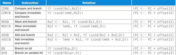
FIGURE E.11.1 The PA-RISC conditional branch instructions.
The 12-bit off set is called offset12 in this table, and the 5-bit immediate is called imm5. The 16 conditions are =, <, < =, odd, signed overflow, unsigned no overflow, zero or no overflow unsigned, never, and their respective complements. The BB instruction selects one of the 32 bits of the register and branches depending on whether its value is 0 or 1. The BVB selects the bit to branch using the shift amount register, a special-purpose register. The subscript notation specifies a bit field.
Synthesized Multiply and Divide
PA-RISC provides several primitives so that multiply and divide can be synthesized in software. Instructions that shift one oper and 1, 2, or 3 bits and then add, trapping or not on overflow, are useful in multiplies. (Alpha also includes instructions that multi ply the second operand of adds and subtracts by 4 or by 8: S4ADD, S8ADD, S4SUB, and S8SUB.) The divide step performs the critical step of nonrestoring divide, adding or subtracting depending on the sign of the prior result. Magenheimer, et al. [1988] measured the size of operands in multiplies and divides to show how well the multiply step would work. Using this data for C programs, Muchnick [1988] found that by making special cases, the average multiply by a constant takes 6 clock cycles and the multiply of variables takes 24 clock cycles. PA-RISC has ten instructions for these operations.
The original SPARC architecture used similar optimizations, but with increasing numbers of transistors the instruction set was expanded to include full multiply and divide operations. PA-RISC gives some support along these lines by putting a full 32-bit integer multiply in the floating-point unit; however, the integer data must first be moved to floating-point registers.
Decimal Operations
COBOL programs will compute on decimal values, stored as four bits per digit, rather than converting back and forth between binary and decimal. PA-RISC has instructions that will convert the sum from a normal 32-bit add into proper decimal digits. It also pro vides logical and arithmetic operations that set the condition codes to test for carries of digits, bytes, or halfwords. These operations also test whether bytes or halfwords are zero. These operations would be useful in arithmetic on 8-bit ASCII characters. Five PA-RISC instructions provide decimal support.
Remaining Instructions
Here are some remaining PA-RISC instructions:
■ Branch vectored shifts an index register left three bits, adds it to a base register, and then branches to the calculated address. It is used for case statements.
■ Extract and deposit instructions allow arbitrary bit fields to be selected from or inserted into registers. Variations include whether the extracted field is sign-extended, whether the bit field is specified directly in the instruction or indirectly in another register, and whether the rest of the register is set to zero or left unchanged. PA-RISC has 12 such instructions.
■ To simplify use of 32-bit address constants, PA-RISC includes ADDIL, which adds a left-adjusted 21-bit constant to a register and places the result in register 1. The following data transfer instruction uses offset addressing to add the lower 11 bits of the address to register 1. This pair of instructions allows PA-RISC to add a 32-bit constant to a base register, at the cost of changing register 1.
■ PA-RISC has nine debug instructions that can set breakpoints on instruction or data addresses and return the trapped addresses.
■ Load and clear instructions provide a semaphore or lock that reads a value from memory and then writes zero.
■ Store bytes short optimizes unaligned data moves, moving either the leftmost or the rightmost bytes in a word to the effective address, depending on the instruction options and condition code bits.
■ Loads and stores work well with caches by having options that give hints about whether to load data into the cache if it’s not already in the cache. For example, a load with a destination of register 0 is defined to be a software-controlled cache prefetch.
■ PA-RISC 2.0 extended cache hints to stores to indicate block copies, recommending that the processor not load data into the cache if it’s not already in the cache. It also can suggest that on loads and stores, there is spatial locality to prepare the cache for subsequent sequential accesses.
■ PA-RISC 2.0 also provides an optional branch target stack to predict indirect jumps used on subroutine returns. Software can suggest which addresses get placed on and removed from the branch target stack, but hardware controls whether or not these are valid.
■ Multiply/add and multiply/subtract are floating-point oper ations that can launch two independent floating-point opera tions in a single instruction in addition to the fused multiply/add and fused multiply/negate/add introduced in version 2.0 of PA-RISC.
E.12 Instructions Unique to ARM
It’s hard to pick the most unusual feature of ARM, but perhaps it is the conditional execution of instructions. Every instruction starts with a 4-bit field that determines whether it will act as a nop or as a real instruction, depending on the condition codes. Hence, conditional branches are properly considered as conditionally executing the unconditional branch instruction. Conditional execution allows avoiding a branch to jump over a single instruction. It takes less code space and time to simply conditionally execute one instruction.
The 12-bit immediate field has a novel interpretation. The eight least significant bits are zero-extended to a 32-bit value, then rotated right the number of bits specified in the first four bits of the field multiplied by two. Whether this split actually catches more immediates than a simple 12-bit field would be an interesting study. One advantage is that this scheme can represent all powers of two in a 32-bit word.
Operand shifting is not limited to immediates. The second register of all arithmetic and logical processing operations has the option of being shifted before being operated on. The shift options are shift left logical, shift right logical, shift right arithmetic, and rotate right. Once again, it would be interesting to see how often operations like rotate-and-add, shift-right-and-test, and so on occur in ARM programs.
Remaining Instructions
Below is a list of the remaining unique instructions of the ARM architecture:
■ Block loads and stores—Under control of a 16-bit mask within the instructions, any of the 16 registers can be loaded or stored into memory in a single instruction. These instructions can save and restore registers on procedure entry and return. These instructions can also be used for block memory copy—offering up to four times the bandwidth of a single register load-store—and today, block copies are the most important use.
■ Reverse subtract—RSB allows the first register to be sub tracted from the immediate or shifted register. RSC does the same thing, but includes the carry when calculating the difference.
■ Long multiplies—Similar to MIPS, Hi and Lo registers get the 64-bit signed product (SMULL) or the 64-bit unsigned prod uct (UMULL).
■ No divide—Like the Alpha, integer divide is not supported in hardware.
■ Conditional trap—A common extension to the MIPS core found in desktop RISCs (Figures E.6.1 through E.6.4), it comes for free in the conditional execution of all ARM instructions, including SWI.
■ Coprocessor interface—Like many of the desktop RISCs, ARM defines a full set of coprocessor instructions: data transfer, moves between general-purpose and coprocessor registers, and coprocessor operations.
■ Floating-point architecture—Using the coprocessor inter face, a floating-point architecture has been defined for ARM. It was implemented as the FPA10 coprocessor.
■ Branch and exchange instruction sets—The BX instruction is the transition between ARM and Thumb, using the lower 31 bits of the register to set the PC and the most significant bit to determine if the mode is ARM (1) or Thumb (0).
E.13 Instructions Unique to Thumb
In the ARM version 4 model, frequently executed procedures will use ARM instructions to get maximum performance, with the less frequently executed ones using Thumb to reduce the overall code size of the program. Since typically only a few procedures dominate execution time, the hope is that this hybrid gets the best of both worlds.
Although Thumb instructions are translated by the hardware into conventional ARM instructions for execution, there are several restrictions. First, conditional execution is dropped from almost all instructions. Second, only the first eight registers are easily available in all instructions, with the stack pointer, link register, and program counter used implicitly in some instructions. Third, Thumb uses a two-operand format to save space. Fourth, the unique shifted immediates and shifted second oper ands have disappeared and are replaced by separate shift instructions. Fifth, the addressing modes are simplified. Finally, putting all instructions into 16 bits forces many more instruction formats.
In many ways, the simplified Thumb architecture is more conventional than ARM. Here are additional changes made from ARM in going to Thumb:
■ Drop of immediate logical instructions—Logical immediates are gone.
■ Condition codes implicit—Rather than have condition codes set optionally, they are defined by the opcode. All ALU instructions and none of the data transfers set the condition codes.
■ Hi/Lo register access—The 16 ARM registers are halved into Lo registers and Hi registers, with the eight Hi registers including the stack pointer (SP), link register, and PC. The Lo registers are available in all ALU operations. Variations of ADD, BX, CMP, and MOV also work with all combinations of Lo and Hi registers. SP and PC registers are also available in variations of data transfers and add immediates. Any other operations on the Hi registers require one MOV to put the value into a Lo register, perform the operation there, and then transfer the data back to the Hi register.
■ Branch/call distance—Since instructions are 16 bits wide, the 8-bit conditional branch address is shifted by 1 instead of by 2. Branch with link is specified in two instructions, concatenating 11 bits from each instruction and shifting them left to form a 23-bit address to load into PC.
■ Distance for data transfer offsets—The offset is now five bits for the general-purpose registers and eight bits for SP and PC.
E.14 Instructions Unique to SuperH
Register 0 plays a special role in SuperH address modes. It can be added to another register to form an address in indirect indexed addressing and PC-relative addressing. R0 is used to load constants to give a larger addressing range than can easily be fit into the 16-bit instructions of the SuperH. R0 is also the only register that can be an operand for immediate versions of AND, CMP, OR, and XOR. Below is a list of the remaining unique details of the SuperH architecture:
■ Decrement and test—DT decrements a register and sets the T bit to 1 if the result is 0.
■ Optional delayed branch—Although the other embedded RISC machines generally do not use delayed branches (see Appen dix B), SuperH offers optional delayed branch execution for BT and BF.
■ Many multiplies—Depending if the operation is signed or unsigned, if the operands are 16 bits or 32 bits, or if the product is 32 bits or 64 bits, the proper multiply instruction is MULS, MULU, DMULS, DMULU, or MUL. The product is found in the MACL and MACH registers.
■ Zero and sign extension—Byte or halfwords are either zero-extended (EXTU) or sign-extended (EXTS) within a 32-bit register.
■ One-bit shift amounts—Perhaps in an attempt to make them fit within the 16-bit instructions, shift instructions only shift a single bit at a time.
■ Dynamic shift amount—These variable shifts test the sign of the amount in a register to determine whether they shift left (positive) or shift right (negative). Both logical (SHLD) and arithmetic (SHAD) instructions are supported. These instructions help offset the 1-bit constant shift amounts of standard shifts.
■ Rotate—SuperH offers rotations by 1 bit left (ROTL) and right (ROTR), which set the T bit with the value rotated, and also have variations that include the T bit in the rotations (ROTCL and ROTCR).
■ SWAP—This instruction either swaps the high and low bytes of a 32-bit word or the two bytes of the rightmost 16 bits.
■ Extract word (XTRCT)—The middle 32 bits from a pair of 32-bit registers are placed in another register.
■ Negate with carry—Like SUBC (Figure E.6.6), except the first operand is 0.
■ Cache prefetch—Like many of the desktop RISCs (Figures E.6.1 through E.6.4), SuperH has an instruction (PREF) to prefetch data into the cache.
■ Test-and-set—SuperH uses the older test-and-set (TAS) instruction to perform atomic locks or semaphores (see Chapter 2). TAS first loads a byte from memory. It then sets the T bit to 1 if the byte is 0 or to 0 if the byte is not 0. Finally, it sets the most significant bit of the byte to 1 and writes the result back to memory.
E.15 Instructions Unique to M32R
The most unusual feature of the M32R is a slight VLIW approach to the pairs of 16-bit instructions. A bit is reserved in the first instruction of the pair to say whether this instruction can be executed in parallel with the next instruction— that is, the two instructions are independent—or if these two must be executed sequentially. (An earlier machine that offered a similar option was the Intel i860.) This feature is included for future implementations of the architecture.
One surprise is that all branch displacements are shifted left 2 bits before being added to the PC, and the lower 2 bits of the PC are set to 0. Since some instructions are only 16 bits long, this shift means that a branch cannot go to any instruction in the program: it can only branch to instructions on word boundaries. A similar restriction is placed on the return address for the branch-and-link and jump-and-link instructions: they can only return to a word boundary. Thus, for a slightly larger branch distance, software must ensure that all branch addresses and all return addresses are aligned to a word boundary. The M32R code space is probably slightly larger, and it probably executes more nop instructions than it would if the branch address was only shifted left 1 bit.
However, the VLIW feature above means that a nop can exe cute in parallel with another 16-bit instruction so that the pad ding doesn’t take more clock cycles. The code size expansion depends on the ability of the compiler to schedule code and to pair successive 16-bit instructions; Mitsubishi claims that code size overall is only 7% larger than that for the Motorola 6800 architecture.
The last remaining novel feature is that the result of the divide operation is the remainder instead of the quotient.
E.16 Instructions Unique to MIPS-16
MIPS-16 is not really a separate instruction set but a 16-bit extension of the full 32-bit MIPS architecture. It is compatible with any of the 32-bit address MIPS architectures (MIPS I, MIPS II) or 64-bit architectures (MIPS III, IV, V). The ISA mode bit determines the width of instructions: 0 means 32-bit-wide instructions and 1 means 16-bit-wide instructions. The new JALX instruction toggles the ISA mode bit to switch to the other ISA. JR and JALR have been redefined to set the ISA mode bit from the most significant bit of the register containing the branch address, and this bit is not considered part of the address. All jump-and-link instructions save the current mode bit as the most significant bit of the return address.
Hence, MIPS supports whole procedures containing either 16-bit or 32-bit instructions, but it does not support mixing the two lengths together in a single procedure. The one exception is the JAL and JALX: these two instructions need 32 bits even in the 16-bit mode, presumably to get a large enough address to branch to far procedures.
In picking this subset, MIPS decided to include opcodes for some three-operand instructions and to keep 16 opcodes for 64-bit operations. The combination of this many opcodes and oper ands in 16 bits led the architects to provide only eight easy-to-use registers—just like Thumb—whereas the other embedded RISCs offer about 16 registers. Since the hardware must include the full 32 registers of the 32-bit ISA mode, MIPS-16 includes move instructions to copy values between the eight MIPS-16 registers and the remaining 24 registers of the full MIPS architecture. To reduce pressure on the eight visible registers, the stack pointer is considered a separate register. MIPS-16 includes a variety of separate opcodes to do data transfers using SP as a base register and to increment SP: LWSP, LDSP, SWSP, SDSP, ADJSP, DADJSP, ADDIUSPD, and DADDIUSP.
To fit within the 16-bit limit, immediate fields have generally been shortened to five to eight bits. MIPS-16 provides a way to extend its shorter immediates into the full width of immediates in the 32-bit mode. Borrowing a trick from the Intel 8086, the EXTEND instruction is really a 16-bit prefix that can be prepended to any MIPS-16 instruction with an address or immediate field. The prefix supplies enough bits to turn the 5-bit field of data transfers and 5-to 8-bit fields of arithmetic immediates into 16-bit constants. Alas, there are two exceptions. ADDIU and DADDIU start with 4-bit immediate fields, but since EXTEND can only supply 11 more bits, the wider immediate is limited to 15 bits. EXTEND also extends the 3-bit shift fields into 5-bit fields for shifts. (In case you were wondering, the EXTEND prefix does not need to start on a 32-bit boundary.)
To further address the supply of constants, MIPS-16 added a new addressing mode! PC-relative addressing for load word (LWPC) and load double (LDPC) shifts an 8-bit immediate field by two or three bits, respectively, adding it to the PC with the lower two or three bits cleared. The constant word or doubleword is then loaded into a register. Thus 32-bit or 64-bit constants can be included with MIPS-16 code, despite the loss of LIU to set the upper register bits. Given the new addressing mode, there is also an instruction (ADDIUPC) to calculate a PC-relative address and place it in a register.
MIPS-16 differs from the other embedded RISCs in that it can subset a 64-bit address architecture. As a result it has 16-bit instruction-length versions of 64-bit data operations: data transfer (LD, SD, LWU), arithmetic operations (DADDU/IU, DSUBU, DMULT/U, DDIV/U), and shifts (DSLL/V, DSRA/V, DSRL/V).
Since MIPS plays such a prominent role in this book, we show all the additional changes made from the MIPS core instructions in going to MIPS-16:
■ Drop of signed arithmetic instructions—Arithmetic instructions that can trap were dropped to save opcode space: ADD, ADDI, SUB, DADD, DADDI, DSUB.
■ Drop of immediate logical instructions—Logical immediates are gone too: ANDI, ORI, XORI.
■ Branch instructions pared down—Comparing two registers and then branching did not fit, nor did all the other comparisons of a register to zero. Hence these instructions didn’t make it either: BEQ, BNE, BGEZ, BGTZ, BLEZ, and BLTZ. As mentioned in Section E.3, to help compensate MIPS-16 includes compare instructions to test if two registers are equal. Since compare and set on less than set the new T register, branches were added to test the T register.
■ Branch distance—Since instructions are 16 bits wide, the branch address is shifted by one instead of by two.
■ Delayed branches disappear—The branches take effect before the next instruction. Jumps still have a one-slot delay.
■ Extension and distance for data transfer offsets—The 5-bit and 8-bit fields are zero-extended instead of sign-extended in 32-bit mode. To get greater range, the immediate fields are shifted left one, two, or three bits depending on whether the data is halfword, word, or doubleword. If the EXTEND prefix is prepended to these instructions, they use the conventional signed 16-bit immediate of the 32-bit mode.
■ Extension of arithmetic immediates—The 5-bit and 8-bit fields are zero-extended for set on less than and compare instructions, for forming a PC-relative address, and for adding to SP and placing the result in a register (ADDIUSP, DADDIUSP). Once again, if the EXTEND prefix is prepended to these instructions, they use the conventional signed 16-bit immediate of the 32-bit mode. They are still sign-extended for general adds and for adding to SP and placing the result back in SP (ADJSP, DADJSP). Alas, code density and orthogonality are strange bedfellows in MIPS-16!
■ Redefining shift amount of 0—MIPS-16 defines the value 0 in the 3-bit shift field to mean a shift of 8 bits.
■ New instructions added due to loss of register 0 as zero—Load immediate, negate, and not were added, since these operations could no longer be synthesized from other instructions using r0 as a source.
E.17 Concluding Remarks
This appendix covers the addressing modes, instruction formats, and all instructions found in ten RISC architectures. Although the later sections of the appendix concentrate on the differences, it would not be possible to cover ten architectures in these few pages if there were not so many similarities. In fact, we would guess that more than 90% of the instructions executed for any of these architectures would be found in Figures E.3.5 through E.3.11. To contrast this homogeneity, Figure E.17.1 gives a summary for four architectures from the 1970s in a format similar to that shown in Figure E.1.1. (Imagine trying to write a single chapter in this style for those architectures!) In the history of computing, there has never been such widespread agreement on computer architecture.
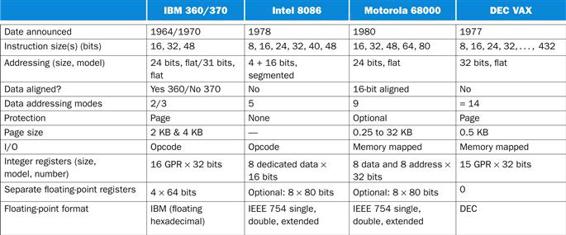
FIGURE E.17.1 Summary of four 1970s architectures.
Unlike the architectures in Figure E.1.1, there is little agreement between these architectures in any category.
This style of architecture cannot remain static, however. Like people, instruction sets tend to get bigger as they get older. Figure E.17.2 shows the genealogy of these instruction sets, and Figure E.17.3 shows which features were added to or deleted from generations of desktop RISCs over time.
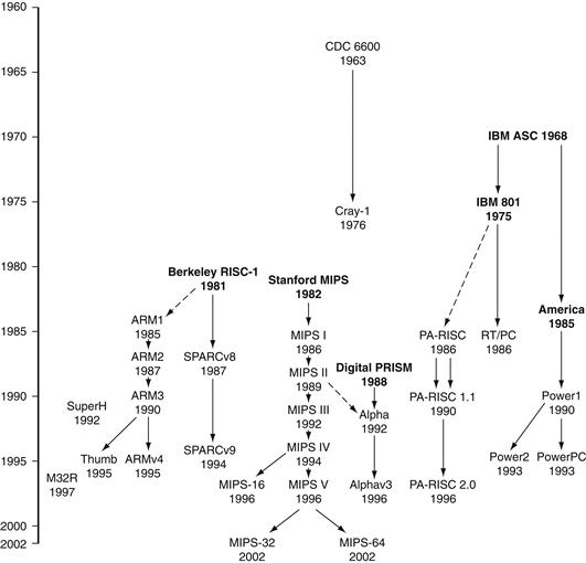
FIGURE E.17.2 The lineage of RISC instruction sets.
Commercial machines are shown in plain text and research machines in bold. The CDC 6600 and Cray-1 were load-store machines with register 0 fixed at 0, and with separate integer and floating-point registers. Instructions could not cross word boundaries. An early IBM research machine led to the 801 and America research projects, with the 801 leading to the unsuccessful RT/PC and America leading to the successful Power architecture. Some people who worked on the 801 later joined Hewlett-Packard to work on the PA-RISC. The two university projects were the basis of MIPS and SPARC machines. According to Furber [1996], the Berkeley RISC project was the inspiration of the ARM architecture. While ARM1, ARM2, and ARM3 were names of both architectures and chips, ARM version 4 is the name of the architecture used in ARM7, ARM8, and StrongARM chips. (There are no ARMv4 and ARM5 chips, but ARM6 and early ARM7 chips use the ARM3 architecture.) DEC built a RISC microprocessor in 1988 but did not introduce it. Instead, DEC shipped workstations using MIPS microprocessors for three years before they brought out their own RISC instruction set, Alpha 21064, which is very similar to MIPS III and PRISM. The Alpha architecture has had small extensions, but they have not been formalized with version numbers; we used version 3 because that is the version of the reference manual. The Alpha 21164A chip added byte and halfword loads and stores, and the Alpha 21264 includes the MAX multimedia and bit count instructions. Internally, Digital names chips after the fabrication technology: EV4 (21064), EV45 (21064A), EV5 (21164), EV56 (21164A), and EV6 (21264). “EV” stands for “extended VAX.”
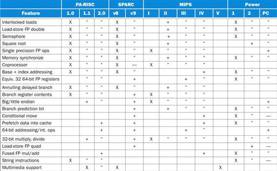
FIGURE E.17.3 Features added to desktop RISC machines.
X means in the original machine, + means added later,” means continued from prior machine, and — means removed from architecture. Alpha is not included, but it added byte and word loads and stores, and bit count and multimedia extensions, in version 3. MIPS V added the MDMX instructions and paired single floating-point operations.
As you can see, all the desktop RISC machines have evolved to 64-bit address architectures, and they have done so fairly painlessly.
We would like to thank the following people for comments on drafts of this appendix: Professor Steven B. Furber, University of Manchester; Dr. Dileep Bhandarkar, Intel Corporation; Dr. Earl Killian, Silicon Graphics/MIPS; and Dr. Hiokazu Takata, Mitsubishi Electric Corporation.
Further Reading
1. Bhandarkar DP. Alpha Architecture and Implementations Newton, MA: Digital Press; 1995.
2. Darcy, J. D., and D. Gay [1996]. “FLECKmarks: Measuring floating point performance using a compliant arithmetic benchmark,” CS 252 class project, U.C Berkeley (see HTTP.CS.Berkeley.EDU/~darcy/Projects/cs252/).
3. Digital Semiconductor [1996]. Alpha Architecture Handbook, Version 3, Maynard, MA: Digital Press, Order number EC-QD2KB-TE (October).
4. Furber SB. ARM System Architecture Harlow, England: Addison-Wesley; 1996; (See www.cs.man.ac.uk/amulet/publications/books/ARMsysArch.).
5. Hewlett-Packard [1994]. PA-RISC 2.0 Architecture Reference Manual, 3rd ed.
6. Hitachi [1997]. SuperH RISC Engine SH7700 Series Programming Manual. (See www.halsp.hitachi.com/tech_prod/ and search for title.).
7. IBM. The PowerPC Architecture San Francisco: Morgan Kaufmann; 1994.
8. Kane G. PA-RISC 2.0 Architecture Upper Saddle River, NJ: Prentice Hall PTR; 1996.
9. Kane G, Heinrich J. MIPS RISC Architecture Englewood Cliffs, NJ: Prentice Hall; 1992.
10. Kissell, K. D. [1997]. MIPS16: High-Density for the Embedded Market. (See www.sgi.com/MIPS/arch/MIPS16/MIPS16.whitepaper.pdf.).
11. Magenheimer DJ, Peters L, Pettis KW, Zuras D. Integer multiplication and division on the HP precision architecture. IEEE Trans on Computers. 1988;37(8):980–990.
12. MIPS [1997]. MIPS16 Application Specific Extension Product Description. (See www.sgi.com/MIPS/arch/MIPS16/mips16.pdf.).
13. Mitsubishi [1996]. Mitsubishi 32-Bit Single Chip Microcomputer M32R Family Software Manual (September).
14. Muchnick SS. Optimizing compilers for SPARC. Sun Technology. 1988;1(3):64–77 Summer.
15. Seal D. Arm Architecture Reference Manual 2nd ed Morgan Kaufmann 2000.
16. Silicon Graphics [1996]. MIPS V Instruction Set. (See www.sgi.com/MIPS/arch/ISA5/#MIPSV_indx.).
17. Sites RL, Witek R, eds. Alpha Architecture Reference Manual. 2nd ed. Newton, MA: Digital Press; 1995.
18. Sloss AN, Symes D, Wright C. ARM System Developer’s Guide San Francisco: Elsevier Morgan Kaufmann; 2004.
19. Sun Microsystems [1989]. The SPARC Architectural Manual, Version 8, Part No. 800-1399-09, August 25.
20. Sweetman D. See MIPS Run 2nd ed Morgan Kaufmann 2006.
21. Taylor, G., P. Hilfinger, J. Larus, D. Patterson, and B. Zorn [1986]. “Evaluation of the SPUR LISP architecture,” Proc. 13th Symposium on Computer Architecture (June), Tokyo.
22. Ungar, D., R. Blau, P. Foley,D.Samples, andD.Patterson [1984]. “Architecture of SOAR: Smalltalk on a RISC,” Proc. 11th Symposium on Computer Architecture (June), Ann Arbor, MI, 188–97.
23. Weaver DL, Germond T. The SPARC Architectural Manual Englewood Cliffs, NJ: Prentice Hall; 1994; Version 9.
24. Weiss S, Smith JE. Power and PowerPC San Francisco: Morgan Kaufman; 1994.