The Maker's Manual: A Practical Guide to the New Industrial Revolution 1st Edition (2015)
Part IV. Giving Life to Objects
Chapter 19. Processing
After many chapters on hardware, let’s go back to software for a moment. Later in this chapter you’ll see how to combine hardware and software again.
Processing is an open source programming environment which lets you easily create images, animations and interactions. Created as a teaching tool, it is now used by thousands of students, researchers, artists, hobbyists, designers, professionals and people in many other categories.
This development environment is very similar to the Arduino’s, since Arduino’s IDE was derived from Processing, so we’re not going to recap the meaning of all the buttons and menu entries. However, the Processing language itself is slightly different, and you are going to see how it can get you started with Object Oriented Programming (OOP). Let’s start with the basics.
Your First Sketch
Like Arduino, Processing’s programs are called sketches, emphasizing their ephemeral nature. The simplest sketch is empty and barely does anything: it only opens a new window called display. Download Processing from https://processing.org/download/ and install as directed on the web site. Run Processing, and an empty sketch will appear. Next, click the Run icon (the leftmost icon in the main window):
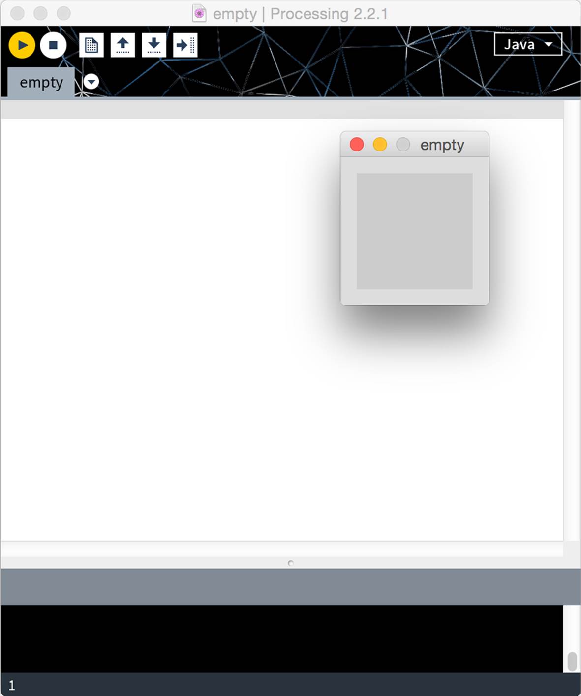
Figure 19-1. An empty sketch opens the display window.
Let’s get it to write the words “Hello World!” on the console (the lower part of the Processing IDE):
print("Hello World!");
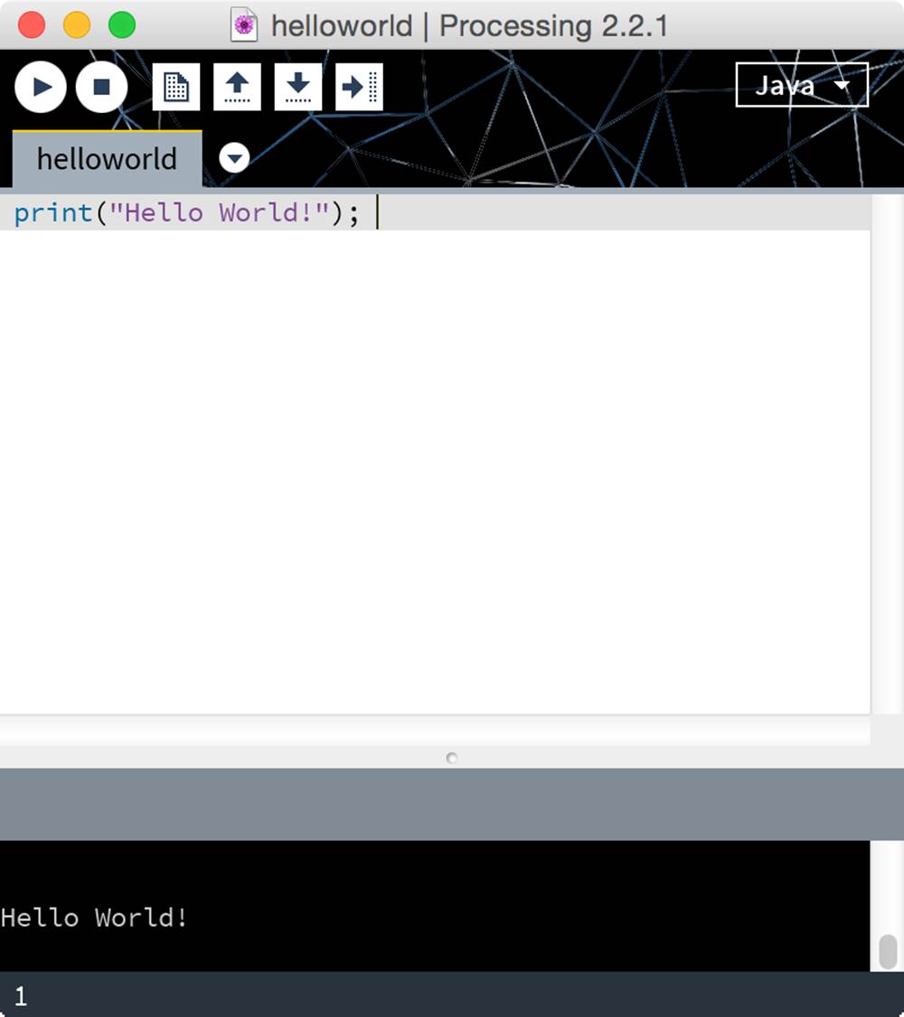
Figure 19-2. A greeting to all from the Processing console
To make your Hello World more appealing, you can do more and try to write on the display. The instructions are slightly more complex, yet it’s not too bad:
fill(0);
text("Hello World", 20, 20);
The fill function defines what color you are going to use for the writing, in this case zero, or black. The text function writes the message you put in quotes as the first parameter, while the second and third parameter specify the position where the writing is going to start from. The position of any point on the display is defined by the pair of x and y coordinates, similar to the Cartesian plane which you became familiar with in school, shown in Figure 19-3.
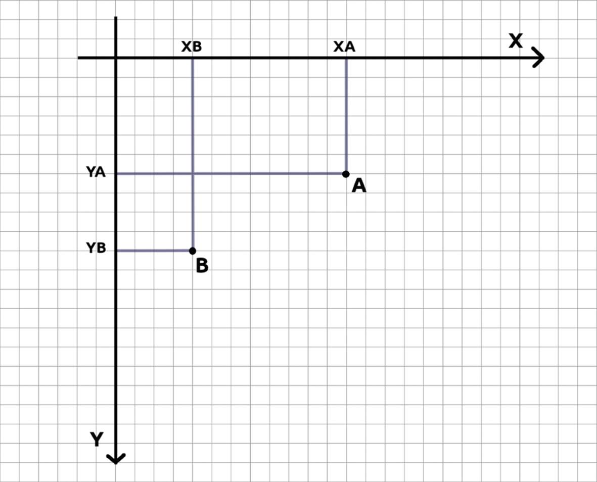
Figure 19-3. The coordinates system used in Processing
As you can see, the y axis points down, unlike standard mathematical convention.It might be hard to remember the difference, but just like any other convention, you get used to it. You could add one further coordinate, the position on the z axis to be used in 3D representations.
Let’s try and execute your sketch (Picture 1).
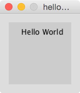
Figure 19-4. A “Hello World!” on your display
Since Processing is widely used for visual representations, you should now to try and draw a line. It’s a very simple instruction:
line(0, 0, 50, 50);
The first two parameters are the coordinates of the first point, the second two of the second. When you run it, it should look like Figure 19-5.
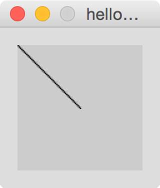
Figure 19-5. Drawing a line.
If you want a comprehensive manual on all the functions, you can click Help on the menu, then Reference: a browser window will open, where you will find all the information you need. With this information and what you have learned in the previous chapters, you shouldn’t have any problem.
Let’s now try to make things more complicated by introducing a loop. You already know that if you have to repeat a series of commands for a number of times, rather than duplicating the instructions, you can use the for statement. Let’s try to reproduce in Processing a pattern you might have drawn a thousand times in a technical drawing or drafting class, shown in Figure 19-6.
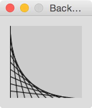
Figure 19-6. Back to school
This looks complicated, right? It is actually rather simple. Start by planning the algorithm, which is the series of instructions you are going to use. You want to connect two points: the first one starts on the (0, 0) coordinates and moves along the y axis; the second one starts in (0, height) and moves parallel to the x axis. The term height refers to the display height; in the same way, you talk about its width.
You are using four variables to define the coordinates of the two points. The first part of this loop is:
int x1 = 0, y1 = 0, x2 = 0, y2 = height;
Notice that you have set variable y2 not to a number, but to something called height. Processing has a number of parameters called system variables. These are variables that Processing uses to tell you about its internal state. In this case, height contains the height in pixels of the default window.
Next, move the first point down and the second one right:
x2 = x2 + 10, y1 = y1 + 10;
Repeat the cycle until the second point reaches the extreme right of the display (or until the first point reaches the bottom). So, the condition is:
x2 < width;
Notice that you are comparing X2 to something called width? That’s another system variable, containing the width in pixels of the default display. Now draw a line between the two points:
line(x1, y1, x2, y2);
Since x1 and y2 won’t change, you can write:
int x1 = 0;
int y2 = height;
for (int y1 = 0, x2 = 0;
x2 < width;
x2 = x2 + 10, y1 = y1 + 10)
{
line(x1, y1, x2, y2);
}
Type this sketch into Processing and see what you get. Notice how complex the for loop is. As you see, it’s possible to use a for loop to change two variables simultaneously, both x and y.
Let’s Get a Move On!
With a few code lines you have created a rather complex, yet static drawing. Let’s move on to something animated: you are going to draw a circle and move it back and forth on the screen. You need to break up the problem into discrete steps. First, you are going to draw a circle, then you’ll see how to move it to the right and, finally, how to make it go back to the left. But first, get comfortable and increase the size of the display with the following instruction:
size(500, 200);
Next, draw a circle, centered vertically on the display: use the ellipse command, which accepts the center coordinates and the dimensions of the two axes as parameters.
ellipse(0, height/2, 50, 50);
Now you can move it right until the center reaches the edge. You can use a simple loop within the draw block. Enter the following into a new Processing sketch:
size(500, 200);
for (int x = 0; x < width; x++)
{
ellipse(x, height/2, 50, 50);
}
Now, launch the sketch. The outcome is not exactly what you expected. You see a bunch of curved lines spread across the screen from left to right, ending with a half-circle of white hugging the right edge of the display.
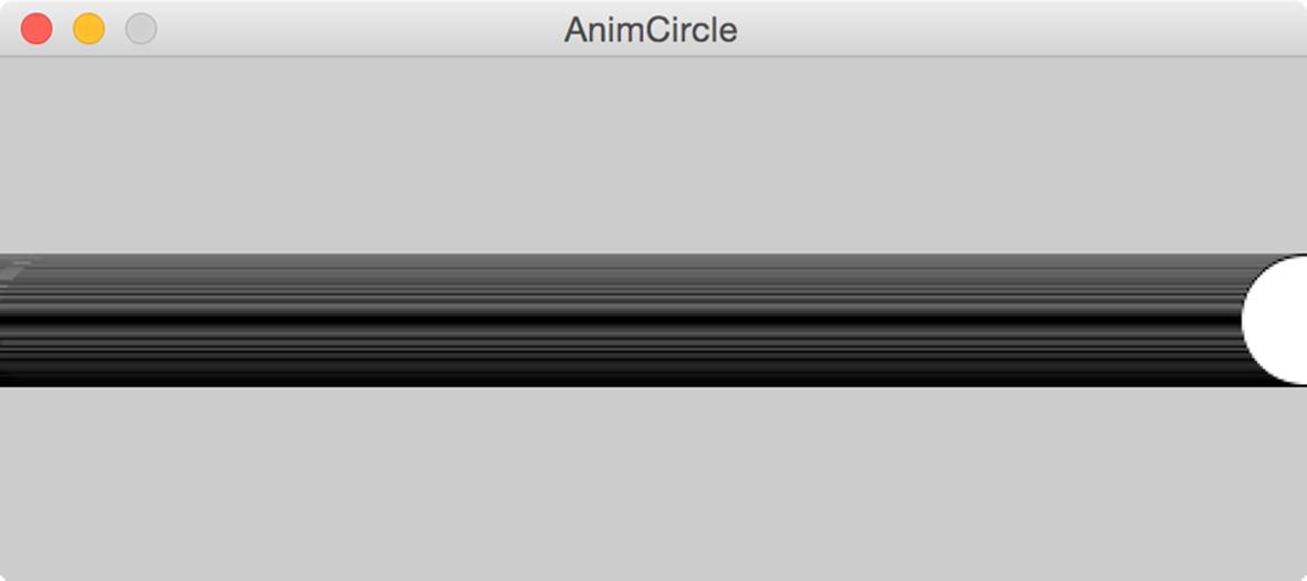
Figure 19-7. Where is your animation?
What if you tried to clear the screen before drawing each circle?
size(500, 200);
for (int x = 0; x < width; x++)
{
background(220);
ellipse(x, height/2, 50, 50);
}
The background instruction fills the whole screen with a specific color, in this case pale grey. You’ll have a more in-depth look at colors later on in this chapter. Is it better? A little, because you don’t see all those curved lines anymore. (As you might have already figured out, those curved lines were the previous circles that had been written on the display.) But... what about the animation? Why can’t you see the circle moving?
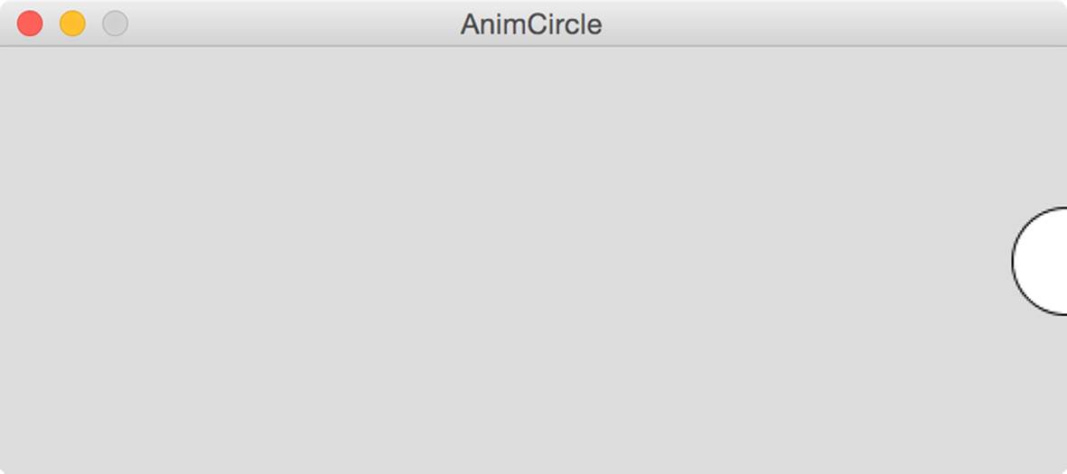
Figure 19-8. A bit better, yet still not there.
The answer is simple: the loop operates too fast for you to see. As in Arduino, the canonical form of Processing sketch structure is made of two blocks: the first one called setup, while the repeated block is here called draw, instead of loop. Why draw? Not just to be different; the metaphor behind Processing is that everything you create in this visual language will be displayed on some kind of device. Unlike Arduino, however, the setup and loop/draw block is not absolutely mandatory in Processing.
You can decide what size you want your display to be, the color of its background and at what speed it is going to perform your instructions; all this information falls into the setup() block.
In order to see the animation, you should have the circle drawn just once for each execution of the draw method (another name for a function). Start a new sketch. First, you need to declare the x variable, which must be outside of the draw block so that it will not be reset each time. Then, you declare the size of the display in the setupmethod. Then, instead of a for loop, you have a draw method, which includes the necessary x increment:
int x = 0;
void setup()
{
size(500,200);
}
void draw()
{
background(220);
ellipse(x, height/2, 50, 50);
x++;
}
Finally, you can see the animation!

Figure 19-9. And yet it moves!
How can you make the circle go back, now? You made the circle move to the right by increasing x by a certain amount; to move the circle to the left, you should just decrease x by the same amount. But how do you know which direction you’re going? And how do you know when it is time to switch? And how can you change the value of x?
First, you set a variable to tell the direction. You call this variable pitch and write its declaration outside of draw and setup, as you have done with x.
int pitch = 1;
The increment instruction is:
x = x + pitch;
The points where you change direction, i.e. where you change sign before the pitch variable, are the windows’ edges:
if (x == 0 || x == width)
{
// change direction
}
The two || (double pipe) characters are a Boolean operator called or: it returns a true value if either the first condition (x == 0) OR the second condition (x == width) is true. If either condition is true, Processing assesses the whole expression in brackets as true. You’ll tell it to then change the sign of the pitch variable, causing it and ultimately the circle to change direction:
if (x == 0 || x == width)
{
pitch = -pitch;
}
The complete sketch code is shown in Example 19-1.
Example 19-1. Your first animation
int x = 0;
int pitch = 1;
void setup()
{
size(500, 200);
}
void draw()
{
background(220);
ellipse(x, height/2, 50, 50);
x = x + pitch;
if (x == 0 || x == width)
{
pitch = - pitch;
}
}
To practice more, try to modify the code to change the speed of the circle. It’s not hard!
How Many Circles?
What if you wanted to draw and move many circles, defining each circle’s speed and color? This is where things get a little complicated. For a single circle, you need two coordinates for its center, two values for height and width (you actually draw ellipses, hence you need two parameters even though they are the same), a variable for the speed and one for the color: you are talking 6 variables for each circle. If you wanted 10 circles, you would have to manage 60 different variables... Ugh!
In this context, arrays come to help you: these are data structures which can contain many items of the same kind. It’s like having a chest of drawers: there’s something in the first drawer, another one in the second, another one in the third and so on for each drawer, but all of them contained in the same chest. Each place (each drawer) is identified with a number, called an index. And as with most things computer-based, the first index is not 1, but 0.
You can only have one variable for each “kind” of data, and this variable is going to be an array. You are going to have an array for the x coordinate of the circle centers, one for the y coordinate, one for the speed and so on. As with a chest of drawers, you have to decide beforehand how many indices an array is going to have. So if you want 10 circles, you’ll write:
int numOfCircles = 10;
int[] x = new int[numOfCircles];
int[] y = new int[numOfCircles];
int[] dim = new int[numOfCircles];
int[] colour = new int[numOfCircles];
int[] pitch = new int[numOfCircles];
Colour vs Color
You’ve already noticed that the color array is spelled “colour”, as if you were members of the British Commonwealth. Did you steal this Processing sketch from the Queen of England?
Of course not. The problem is that color is a protected Processing system variable, which you’re not allowed to use as your own variable. You can tell because in the Processing IDE, the word color is literally a different color than the other words; that indicates a restricted word. By calling the array “colour” you avoid the restriction problem, while also making it clear what the array controls.
To create an array, you need to specify the kind of data that the drawers are going to contain, followed by square brackets before the name, and its length in the second part of the instruction. You also need to use the keyword new because you are creating a peculiar variable: an object.
The centers of the circles will start at 0 on the x axis, and will be spaced equally throughout the y axis:
int distance = height / numOfCircles;
int temp = distance / 2;
for (int i = 0; i < numOfCircles; i++)
{
y[i] = temp;
temp = temp + distance;
}
To decide upon size and color of every circle, you’ll use the random function, which gives you random numbers (pseudo-random actually, because even though they seem to be random, they are generated by an algorithm) between the two numbers given as parameters. The random function renders float values, i.e. decimal numbers, yet you need whole values; to convert them, use the int keyword:
dim[i] = int(random(5, 2.5 * distance));
Do the same with colors. For now, you can stick to the grey scale:
colour[i] = int(random(255));
Finally, the pitch:
pitch[i] = int(random(1, 15));
Because the pitch is no longer constantly 1 or -1, certain circles might not necessarily reach the exact edge of the display before returning. A small circle with a large pitch could disappear to the left or the right before it reverts:
if (x[i] > width || x[i] < 0)
{
pitch[i] = - pitch[i];
}
Example 19-2 shows the complete listing, and you can see the sketch in action in Figure 19-10.
Example 19-2. As many circles as you can
int numberOfCircles = 10;
int[] x = new int[numberOfCircles];
int[] y = new int[numberOfCircles];
int[] dim = new int[numberOfCircles];
int[] colour = new int[numberOfCircles];
int[] pitch = new int[numberOfCircles];
void setup()
{
size(500, 200);
int distance = height / numberOfCircles;
int temp = distance / 2;
for (int i = 0; i < numberOfCircles; i++)
{
y[i] = temp;
temp = temp + distance;
dim[i] = int(random(5, 2.5 * distance));
colour[i] = int(random(255));
pitch[i] = int(random(1, 15));
}
}
void draw()
{
background(200);
for (int i = 0; i < numberOfCircles; i++)
{
x[i] = x[i] + pitch[i];
fill(colour[i]);
ellipse(x[i], y[i], dim[i], dim[i]);
if (x[i] > width || x[i] < 0) {
pitch[i] = - pitch[i];
}
}
}
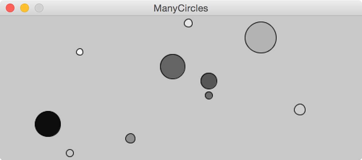
Figure 19-10. Your circles in movement.
What if you wanted colored circles (Figure 19-11)? As we mentioned, Processing puts at your disposal the color variable, for which you can use its three components RGB (Red, Green and Blue). Change the sketch by modifying the color array:
color[] colour = new color[numberOfCircles];
Next, initialize it with random values. Change the definition of color[i] in setup to:
colour[i] = color(int(random(255)), int(random(255)), int(random(255)));
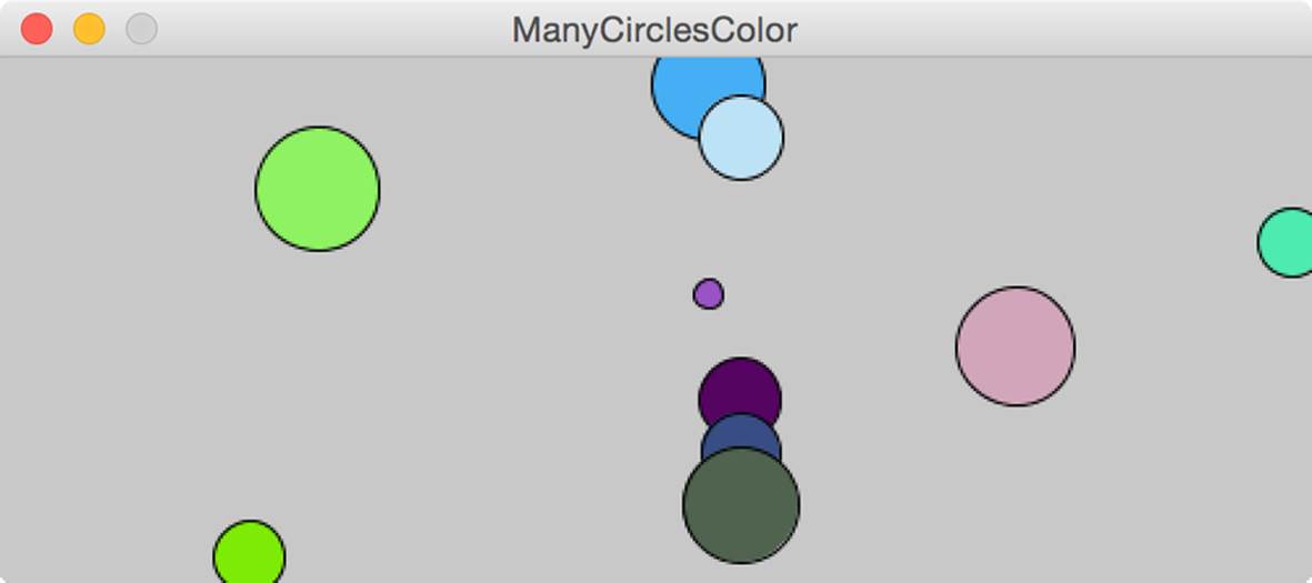
Figure 19-11. You can color all circles at once.
See how easy that was? Thanks to the power of arrays, you can modify the color of 10 circles at once. If you wanted to, you could increase the number of circles to nearly any number you wanted, just by modifying a single line in your sketch!
I’ve Got The Power!
Now that you understand the basics, you can try to interact with the computer. Processing is capable of reacting to the mouse position and mouse clicks, to your pressing keys, and to other events. For instance, let’s try and have a dot drawn wherever you click the mouse. The position of the mouse pointer is identified with the mouseX and mouseY system variables. To know if you are pressing the mouse button, use the mousePressed system variable, which can take the true or false values. The sketch is very simple, you just need to put it into a draw block:
void draw()
{
if (mousePressed)
{
point(mouseX, mouseY);
}
}
There isn’t much to see, right? Increase the dot size by putting this at the top of the draw block:
strokeWeight(10);
As you can guess, by increasing the parameter, the size of the dot increases. Alternately, you could put the strokeWeightinstruction in setup.
You can also use the keyboard to give Processing some information. Each time a key is pressed on the keyboard, that generates an event, which Processing knows about. You will use the keyPressed method to see if a key press event has occurred.
Once you are within the keyPressed method, you can use the key system variable to find out which key has been pressed. If, for instance, you wanted to print to the console everything you type, you could use the simple sketch (you must have a draw function, even an empty one, in order forkeypressed to work):
void keyPressed()
{
print(key);
}
void draw() {
}
Programming with Cartoons
In cartoons it is very frequent to find worlds in which objects speak and are alive. In such a fantastic worlds you may hear dialogues of the following kind:
Dog: “Home, why are you sad?”
Home: “Because today is such a beautiful day and I am all dark...so I am too hot!”
Dog: “No problem, paint yourself white!”
Home: “Great idea!”
What’s all this got to do with Processing? It is pertinent because this type of world is the essence of the object oriented programming: it is not you saying precisely what has to be done (take the paintbrush, dip it in white paint, paint the home walls several times, then wait and repeat for three times), but you just tell the objects to do something, giving them the responsibility of managing themselves: “Home, paint yourself white!”.
Let’s try to understand the difference. You want to simulate a surface (like a body of water) onto which water drops fall, and rings become larger little by little and eventually disappear. tart with a single drop:
Example 19-3. Water drop simulation
int bg_color = 200;
int x;
int y;
int rayMinimum = 10;
int rayMaximum = 100;
int ray = 10;
int initialColor = 100;
int colour = initialColor;
void setup() {
size(200, 200);
x = width/2;
y = height/2;
fill(bg_color);
}
void draw() {
background(bg_color);
stroke(colour);
ellipse(x, y, ray, ray);
ray = ray + 1;
colour = colour + 1;
if (ray > rayMaximum) {
ray = rayMinimum;
colour = initialColor;
}
}
So far there is nothing new here; we’re using the same techniques you saw earlier. What you would like, now, is to create a drop that you can instruct like some anthropomorphic cartoon character:
void draw() {
background(bg_color);
drop.update();
drop.draw();
}
As you can see, the code is much cleaner and more comprehensible: given a drop, you just need to ask it to update itself and draw itself.
Classes and Objects
Of course, first you have to create this drop and then insert into it all instructions you had in the droplet sketch.
The drop is an object, which means it is characterized by a series of operations (in your case, update and draw) and by some properties, which keep track of the effects of such operations (e.g., positions, speeds, dimensions, and colors). It is correct to suppose that all drops behave in the same way, or at least in object oriented programming it works this way. So you can say that all drops are defined by a sort of blueprint that says how they are made and how they behave. Such a blueprint is called class. In particular, your class will be called Drop and the drops are calledinstances of the Drop class.
Before you do anything, save your sketch as DropTest. Next, create a new class by clicking on the arrow on the right side of your programming environment, then click on the New Tab menu (Figure 19-12). Processing will ask you to name your file and you will type Drop, as shown inFigure 19-12. Click the OK button and the job is done!
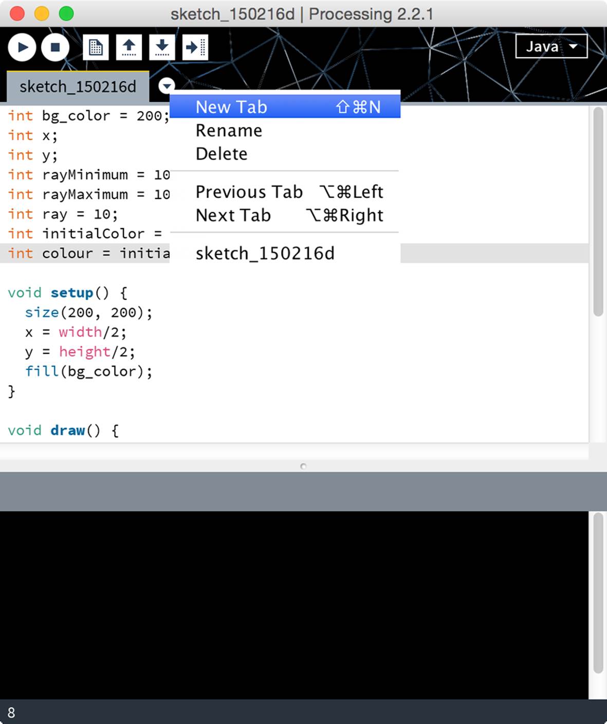
Figure 19-12. Adding a new file to your project.
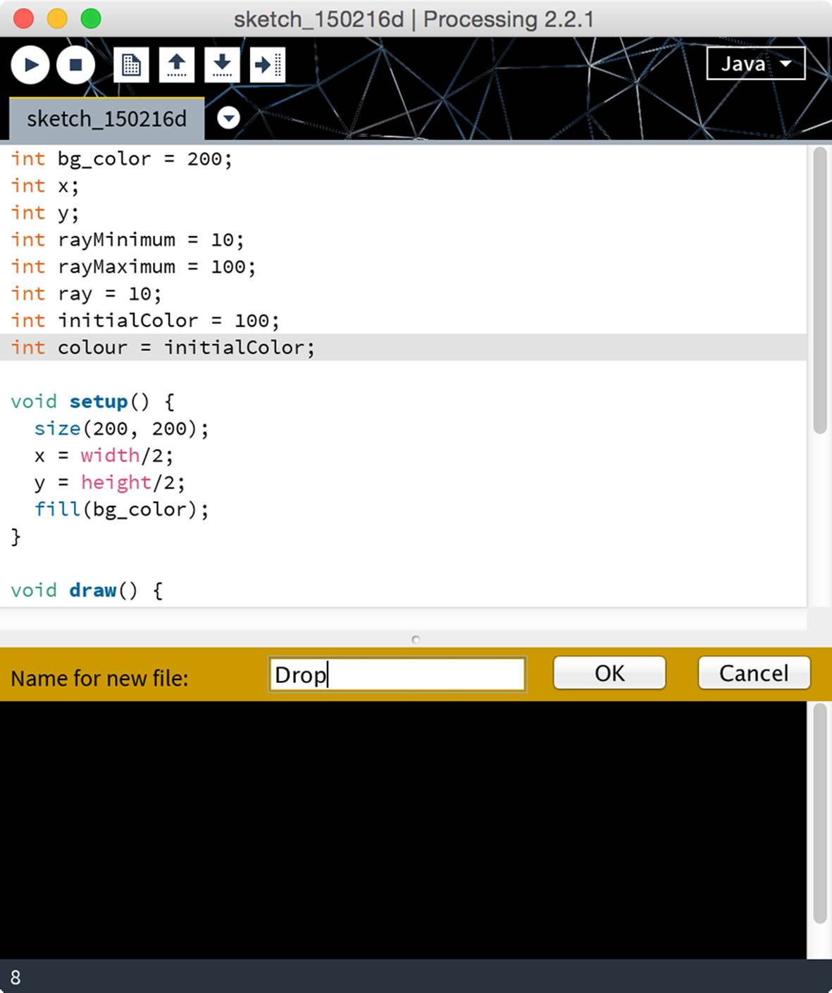
Figure 19-13. Choosing a name for the new file.
Now that the file is created, define the class with the following. Everything else you type as part of the class will go inside Drop’s { and }.
class Drop {
}
In the Drop class, include all information you need:
int x;
int y;
int rayMinimum = 10;
int rayMaximum = 100;
int ray = 10;
int initialColor = 100;
int colour = initialColor;
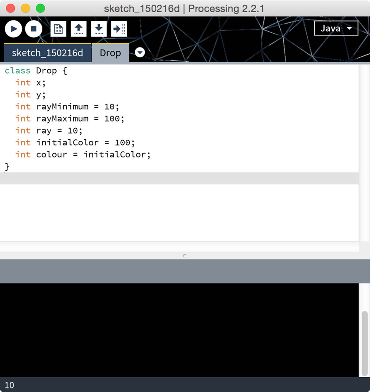
Figure 19-14. A new home for your Drop.
I Want... A New One!
When you create a new drop you have to decide where its center is, what its minimum radius (the variable ray) and maximum radius are and what is its initial color. To create an object, a special method called constructor is used, whose name (in Processing, and some other languages like C++) is always the same as the class name. In the constructor the parameters of the object are usually initialized:
Drop(int x, int y, int rMin, int rMax, int col){
this.x = x;
this.y = y;
this.rayMinimum = rMin;
this.rayMaximum = rMax;
this.ray = rMin;
this.initialColor = col;
this.colour = col;
}
The word this refers to the object itself, so the instruction this.rayMinimum = rMin; means “take the rayMinimum variable of the drop object you are working on and set it to the value of the rMin parameter”.
Ok, But What Shall I Do With it?
In your main sketch you will ask the drop to update and draw itself. Write the two methods, using the code you have removed from the other part:
void update(){
ray = ray + 1;
colour = colour + 1;
if (ray > rayMaximum) {
ray= rayMinimum;
colour = initialColor;
}
}
void draw(){
stroke(colour);
ellipse(x, y, ray, ray);
}
If you read that carefully, you’ll notice that you didn’t use the this keyword. This is because it is optional most of the time; in the constructor you used it because two of the arguments that it got passed (x and y) had the same names as two properties of your Drop class, so you needed to be explicit for these assignments; the others were simply kept consistent.
The update and draw methods do not give you anything back as return values when you call them, so before them you shall write void. Done! Your Drop class is completed. Now you have to use it.
Using a Drop
Let’s go back to your main sketch. To create a new drop, and in general a new object, you have to use the new command followed by the object’s name, with the necessary parameters as needed, as you have already seen in the examples with arrays. Before the sketch, you have to declare that you want to use an object you will call drop of the Drop type:
Drop drop;
In the setup, you just need to add the instruction:
drop = new Drop(width/2, height/2,
rayMinimum, rayMaximum,
initialColor);
and… there you go! Let’s try to execute the sketch and you will have the same result, but with a cleaner and more manageable code:
Example 19-4. The sketch (DropTest) needed to use the drop class
int bg_color = 200;
int rayMinimum = 10;
int rayMaximum = 100;
int ray = 10;
int initialColor = 100;
Drop drop;
void setup() {
size(200, 200);
fill(bg_color);
drop = new Drop(width/2, height/2,
rayMinimum, rayMaximum,
initialColor);
}
void draw() {
background(bg_color);
drop.update();
drop.draw();
}
Example 19-5. The Drop class
class Drop {
int x;
int y;
int rayMinimum = 10;
int rayMaximum = 100;
int ray = 10;
int initialColor = 100;
int colour = initialColor;
Drop(int x, int y, int rMin, int rMax, int col) {
this.x = x;
this.y = y;
this.rayMinimum = rMin;
this.rayMaximum = rMax;
this.ray = rMin;
this.initialColor = col;
this.colour = col;
}
void update() {
ray = ray + 1;
colour = colour + 1;
if (ray > rayMaximum) {
ray= rayMinimum;
colour = initialColor;
}
}
void draw() {
stroke(colour);
ellipse(x, y, ray, ray);
}
}
Raindrops keep fallin’ on my head…
What if you wanted many drops? For example, you want a new drop to fall any time you click on the mouse. In the main sketch you will need to keep track of all drops, however you don’t know how many drops you are going to get, so the array won’t work. A structure called ArrayList is needed: it is similar to the array, but it also allows you to have a variable number of elements. To create a list of drops replace the line Drop drop; at the top of the DropTest sketch with the following:
ArrayList<Drop> drops = new ArrayList<Drop>();
So, when you define the drops variable, you are not only saying that it is of an ArrayList type, but you are also indicating that the list will contain objects of the Drop type. The ArrayList is a class, so it has methods you can call.
The first method that interests you is the add method, which allows you to add a drop to the list: drops.add(drop)
With the size method you can know how many drops you have got and use a traditional for cycle to draw all drops. Change DropTest’s draw method to the following:
void draw() {
background(bg_color);
for (int i = 0; i < drops.size(); i++){
Drop drop = drops.get(i);
drop.update();
drop.draw();
}
}
To get the object in the n-th position you use the get method using its position in the list as a parameter; just like with arrays, the first element of the list has zero index.
To add a circle to each click of the mouse you can use the mousePressed method that reacts to the “mouse button has been clicked” event:
void mousePressed(){
Drop drop = new Drop(mouseX, mouseY,
rayMinimum, rayMaximum,
initialColor);
drops.add(drop);
}
Modify the setup method to appear as follows (you no longer need to define a Drop object there):
void setup() {
size(200, 200);
fill(bg_color);
}
Launch the sketch and try to click a couple of times: can you see the power you have at your disposal?
If someone creates a class and puts it at your disposal, it is very easy for you to write a sketch that uses it without knowing how it is made. The only thing you need to know is how to use it. It’s a bit like going to a restaurant and order a meal: you don’t need to know how it is cooked, you just need to order one from the person taking your order (an instance of Waiter) and then you can simply devour it. In turn, the waiter will not cook it directly, but he will ask someone (evidently a cook object of the Chef type) to prepare one. So, you just know that, once you have ordered it from the waiter, the meal will get to your table ready to be eaten and this is all you need to know. In this way you can obtain extremely complex systems by making many small, simple-to-manage objects interact with one another: instead of a very complicated sketch you will benefit from collaboration among objects, each one with its specific responsibilities whose complexities are hidden to you. Isn’t it great?
Let’s now turn attention to the Drop class, and make some changes. To improve the effect you get when the circles overlap, you’re better off having them empty:
void draw(){
noFill();
stroke(colour);
ellipse(x, y, ray, ray);
}
After you click many times, it gets very cluttered. So why don’t you modify the Drop class so that, once the rayMaximum is reached, the drop disappears? Actually this is the way it goes in the real world...How can you do it? As always, there are different ways to reach your goal. How can you know if the drop has got to its largest dimension? Let’s ask it to the drop: who can know this better than it? However, you don’t know the internal functioning of the drop, so you can’t ask it “have you reached your largest dimension?” because you don’t know if it is able to tell you; you can imagine this, but you don’t know it for sure. This principle is called information hiding and following it helps you write better sketches. Now, let’s have the drop use a Boolean method, i.e. that returns one of the two possible values true or false, called disappear:
boolean disappear() {
return ray > rayMaximum;
}
In the same way, it is of no interest to you to increase the drop’s dimensions beyond its maximum value, so you can trim down Drop’s update method to:
void update(){
ray = ray + 1;
colour = colour + 1;
}
If the drop is no longer visible (because it has reached its largest dimension or for any other reason you are not aware of), it doesn’t interest you anymore. Let’s go back to the sketch that uses the Drop catch and modify its draw remove the drop from the drops list. Change the for loop as shown:
for (int i = 0; i < drops.size(); i++){
Drop drop = drops.get(i);
if (drop.disappear()){
drops.remove(drop);
} else {
drop.update();
drop.draw();
}
}
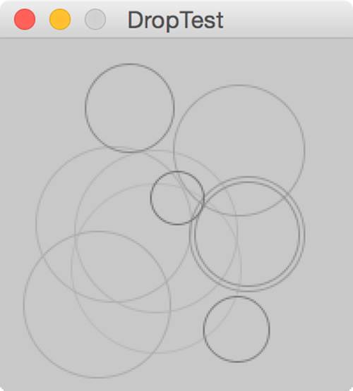
Figure 19-15. Your rain animation is completed
Processing, Meet Arduino!
Many artists use Processing for interactive installations, gathering information from the environment. Why can’t you do it too? Let’s write a sketch that interacts with Arduino. The communication channel we’ll use is the serial port, so suppose you write a very simple Arduino sketch that slowly counts from 1 to 255, and then down again, all the while sending that number to the serial port. What you have to do in Processing is to read this data and use them for your purposes, for example drawing a circle with its radius proportional to the value sent by the Arduino.
Libraries
As with Python, Processing is not able to read the data from the serial port and needs to use an external library. To use a library, you first have to import it, i.e. tell Processing you want to use it:
import processing.serial.*;
The processing.serial library contains a class called Serial, which represents a serial port. To use it, you first have to declare it:
Serial SerialPort;
To build a new object of the Serial type you need to know how it is called. For this reason you will not directly ask an object, but the Serial class itself:
String nameSerial = Serial.list()[0];
The methods of this type are called static or class methods. In this case you can ask the class what’s the name of the first serial port, which is usually the one used by Arduino.
But not always...
The Arduino is usually, but not always found on the first serial port. If Processing can’t find your Arduino on the first port, try changing the index to [1] , [2] or something else. If you get stuck, add this line to your Processing sketch and run it (the serial port listed in the Processing console will match the one you use in the Arduino IDE):
println(Serial.list());
When you find your Arduino’s port in the list, start counting from 0 until you reach the one corresponding to the Arduino. This is the number to use in place of 0 when you define nameSerial.
You’ll use nameSerial to create your Serial object:
SerialPort =
new Serial(this, nameSerial, 9600);
As you saw in “Arduino and the Raspberry Pi”, 9600 indicates the speed at which you want the port to work. Make sure that it corresponds to the speed you have used in the sketch of Arduino. You want Processing to activate itself only when Arduino has finished transmitting its data and you can make sure that nothing happens until you press the Enter or Return key:
SerialPort.bufferUntil('\n');
In this way Processing temporarily stores all data coming onto the serial port into a buffer, i.e. a temporary container. When the “enter” character arrives, Processing automatically calls the serialEvent method where you can read what is written in the buffer, excluding the Enter/Return character you are not interested in:
dataRead = SerialPort.readStringUntil('\n');
Remove spaces and tabs from the string:
dataRead = trim(dataRead);
Before being able to use the read value, you have to turn it into a number, remembering that on analog ports the Arduino reads values from 0 to 1023, if you wanted a radius (the variable ray) between 10 and 100 you should use the mapfunction, which allows you to pass from a scale of values to another:
ray = map(int(dataRead), 0, 255, 10, 100);
Example 19-6 shows the complete listing. Before you can use this, set up your Arduino with the circuit shown in Figure 16-12, and load the sketch shown in Example 16-9.
Example 19-6. Reading from the serial port
import processing.serial.*;
Serial SerialPort;
String dataRead;
float ray = 10;
void setup()
{
size(200, 200); //make your canvas 200 x 200 pixels big
SerialPort = new Serial(this, Serial.list()[0], 9600);
SerialPort.bufferUntil('\n');
}
void draw()
{
background(200);
ellipse(width/2, height/2, ray, ray);
}
void serialEvent( Serial SerialPort)
{
dataRead = SerialPort.readStringUntil('\n');
if (dataRead != null)
{
dataRead = trim(dataRead);
println(dataRead);
}
ray = map(int(dataRead), 0, 255, 10, 100);
println(ray);
}
Let’s conclude the chapter with some exercises:
§ Modify the code of Example 19-2 to make sure that the circles bounce off, not when their center reaches the border of the display, but when the perimeter touches it.
§ Write a sketch so that at each click of the mouse, a line gets drawn that links the point where the pointer currently is to the last point that was created. At the first click, the sketch has to draw a point. The thickness, color and opacity of each line (see Processing’s stroke function) must be random. After 20 clicks the screen has to clean itself.
§ Modify the last version of DropTest to make sure that, next to the drops created with a mouse click, every now and then a new drop appears in a random point of the display.
All materials on the site are licensed Creative Commons Attribution-Sharealike 3.0 Unported CC BY-SA 3.0 & GNU Free Documentation License (GFDL)
If you are the copyright holder of any material contained on our site and intend to remove it, please contact our site administrator for approval.
© 2016-2026 All site design rights belong to S.Y.A.