Learning Internet of Things (2015)
Chapter 1. Preparing our IoT Projects
This book will cover a series of projects for Raspberry Pi that cover very common and handy use cases within Internet of Things (IoT). These projects include the following:
· Sensor: This project is used to sense physical values and publish them together with metadata on the Internet in various ways.
· Actuator: This performs actions in the physical world based on commands it receives from the Internet.
· Controller: This is a device that provides application intelligence to the Internet.
· Camera: This is a device that publishes a camera through which you will take pictures.
· Bridge: This is the fifth and final project, which is a device that acts as a bridge between different protocols. We will cover this at an introductory level later in the book (Chapter 8, Creating Protocol Gateways, if you would like to take a look at it now), as it relies on the IoT service platform.
Before delving into the different protocols used in Internet of Things, we will dedicate some time in this chapter to set up some of these projects, present circuit diagrams, and perform basic measurement and control operations, which are not specific to any communication protocol. The following chapters will then use this code as the basis for the new code presented in each chapter.
Tip
All of the source code presented in this book is available for download. The source code for this chapter and the next one can be downloaded from https://github.com/Clayster/Learning-IoT-HTTP.
Along with the project preparation phase, you will also learn about some of the following concepts in this chapter:
· Development using C# for Raspberry Pi
· The basic project structure
· Introduction to Clayster libraries
· The sensor, actuator, controller, and camera projects
· Interfacing the General Purpose Input/Output pins
· Circuit diagrams
· Hardware interfaces
· Introduction to interoperability in IoT
· Data persistence using an object database
Creating the sensor project
Our first project will be the sensor project. Since it is the first one, we will cover it in more detail than the following projects in this book. A majority of what we will explore will also be reutilized in other projects as much as possible. The development of the sensor is broken down into six steps, and the source code for each step can be downloaded separately. You will find a simple overview of this here:
1. Firstly, you will set up the basic structure of a console application.
2. Then, you will configure the hardware and learn to sample sensor values and maintain a useful historical record.
3. After adding HTTP server capabilities as well as useful web resources to the project, you will publish the sensor values collected on the Internet.
4. You will then handle persistence of sampled data in the sensor so it can resume after outages or software updates.
5. The next step will teach you how to add a security layer, requiring user authentication to access sensitive information, on top of the application.
6. In the last step, you will learn how to overcome one of the major obstacles in the request/response pattern used by HTTP, that is, how to send events from the server to the client.
Tip
Only the first two steps are presented here, and the rest in the following chapter, since they introduce HTTP. The fourth step will be introduced in this chapter but will be discussed in more detail in Appendix C, Object Database.
Preparing Raspberry Pi
I assume that you are familiar with Raspberry Pi and have it configured. If not, refer to http://www.raspberrypi.org/help/faqs/#buyingWhere.
In our examples, we will use Model B with the following:
· An SD card with the Raspbian operating system installed
· A configured network access, including Wi-Fi, if used
· User accounts, passwords, access rights, time zones, and so on, all configured correctly
Note
I also assume that you know how to create and maintain terminal connections with the device and transfer files to and from the device.
All our examples will be developed on a remote PC (for instance, a normal working laptop) using C# (C + + + + if you like to think of it this way), as this is a modern programming language that allows us to do what we want to do with IoT. It also allows us to interchange code between Windows, Linux, Macintosh, Android, and iOS platforms.
Tip
Don't worry about using C#. Developers with knowledge in C, C++, or Java should have no problems understanding it.
Once a project is compiled, executable files are deployed to the corresponding Raspberry Pi (or Raspberry Pi boards) and then executed. Since the code runs on .NET, any language out of the large number of CLI-compatible languages can be used.
Tip
Development tools for C# can be downloaded for free from http://xamarin.com/.
To prepare Raspberry for the execution of the .NET code, we need to install Mono, which contains the Common Language Runtime for .NET that will help us run the .NET code on Raspberry. This is done by executing the following commands in a terminal window in Raspberry Pi:
$ sudo apt-get update
$ sudo apt-get upgrade
$ sudo apt-get install mono-complete
Your device is now ready to run the .NET code.
Clayster libraries
To facilitate the development of IoT applications, this book provides you with the right to use seven Clayster libraries for private and commercial applications. These are available on GitHub with the downloadable source code for each chapter. Of these seven libraries, two are provided with the source code so that the community can extend them as they desire. Furthermore, the source code of all the examples shown in this book is also available for download.
The following Clayster libraries are included:
|
Library |
Description |
|
Clayster.Library.Data |
This provides the application with a powerful object database. Objects are persisted and can be searched directly in the code using the object's class definition. No database coding is necessary. Data can be stored in the SQLite database provided in Raspberry Pi. |
|
Clayster.Library.EventLog |
This provides the application with an extensible event logging architecture that can be used to get an overview of what happens in a network of things. |
|
Clayster.Library.Internet |
This contains classes that implement common Internet protocols. Applications can use these to communicate over the Internet in a dynamic manner. |
|
Clayster.Library.Language |
This provides mechanisms to create localizable applications that are simple to translate and that can work in an international setting. |
|
Clayster.Library.Math |
This provides a powerful extensible, mathematical scripting language that can help with automation, scripting, graph plotting, and others. |
|
Clayster.Library.IoT |
This provides classes that help applications become interoperable by providing data representation and parsing capabilities of data in IoT. The source code is also included here. |
|
Clayster.Library.RaspberryPi |
This contains Hardware Abstraction Layer (HAL) for Raspberry Pi. It provides object-oriented interfaces to interact with devices connected to the General Purpose Input/Output (GPIO) pins available. The source code is also included here. |
Hardware
Our sensor prototype will measure three things: light, temperature, and motion. To summarize, here is a brief description of the components:
· The light sensor is a simple ZX-LDR analog sensor that we will connect to a four-channel (of which we use only one) analog-to-digital converter (Digilent Pmod AD2), which is connected to an I2C bus that we will connect to the standard GPIO pins for I2C.
Note
The I2C bus permits communication with multiple circuits using synchronous communication that employs a Serial Clock Line (SCL) and Serial Data Line (SDA) pin. This is a common way to communicate with integrated circuits.
· The temperature sensor (Texas Instruments TMP102) connects directly to the same I2C bus.
· The SCL and SDA pins on the I2C bus use recommended pull-up resistors to make sure they are in a high state when nobody actively pulls them down.
· The infrared motion detector (Parallax PIR sensor) is a digital input that we connect to GPIO 22.
· We also add four LEDs to the board. One of these is green and is connected to GPIO 23. This will show when the application is running. The second one is yellow and is connected to GPIO 24. This will show when measurements are done. The third one is yellow and is connected to GPIO 18. This will show when an HTTP activity is performed. The last one is red and is connected to GPIO 25. This will show when a communication error occurs.
· The pins that control the LEDs are first connected to 160 Ω resistors before they are connected to the LEDs, and then to ground. All the hardware of the prototype board is powered by the 3.3 V source provided by Raspberry Pi. A 160 Ω resistor connected in series between the pin and ground makes sure 20 mA flows through the LED, which makes it emit a bright light.
Tip
For an introduction to GPIO on Raspberry Pi, please refer to http://www.raspberrypi.org/documentation/usage/gpio/.
Two guides on GPIO pins can be found at http://elinux.org/RPi_Low-level_peripherals.
For more information, refer to http://pi.gadgetoid.com/pinout.
The following figure shows a circuit diagram of our prototype board:
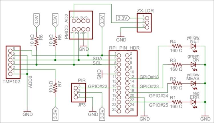
A circuit diagram for the Sensor project
Tip
For a bill of materials containing the components used, see Appendix R, Bill of Materials.
Interacting with our hardware
We also need to create a console application project in Xamarin. Appendix A, Console Applications, details how to set up a console application in Xamarin and how to enable event logging and then compile, deploy, and execute the code on Raspberry Pi.
Interaction with our hardware is done using corresponding classes defined in the Clayster.Library.RaspberryPi library, for which the source code is provided. For instance, digital output is handled using the DigitalOutput class and digital input with the DigitalInputclass. Devices connected to an I2C bus are handled using the I2C class. There are also other generic classes, such as ParallelDigitalInput and ParallelDigitalOutput, that handle a series of digital input and output at once. The SoftwarePwm class handles a software-controlled pulse-width modulation output. The Uart class handles communication using the UART port available on Raspberry Pi. There's also a subnamespace called Devices where device-specific classes are available.
In the end, all classes communicate with the static GPIO class, which is used to interact with the GPIO layer in Raspberry Pi.
Each class has a constructor that initializes the corresponding hardware resource, methods and properties to interact with the resource, and finally a Dispose method that releases the resource.
Tip
It is very important that you release the hardware resources allocated before you terminate the application. Since hardware resources are not controlled by the operating system, the fact that the application is terminated is not sufficient to release the resources. For this reason, make sure you call the Dispose methods of all the allocated hardware resources before you leave the application. Preferably, this should be done in the finally statement of a try-finally block.
Interfacing the hardware
The hardware interfaces used for our LEDs are as follows:
private static DigitalOutput executionLed = new DigitalOutput (23, true);
private static DigitalOutput measurementLed = new DigitalOutput (24, false);
private static DigitalOutput errorLed = new DigitalOutput (25, false);
private static DigitalOutput networkLed = new DigitalOutput (18, false);
We use a DigitalInput class for our motion detector:
private static DigitalInput motion = new DigitalInput (22);
With our temperature sensor on the I2C bus, which limits the serial clock frequency to a maximum of 400 kHz, we interface as follows:
private static I2C i2cBus = new I2C (3, 2, 400000);
private static TexasInstrumentsTMP102 tmp102 = new TexasInstrumentsTMP102 (0, i2cBus);
We interact with the light sensor using an analog-to-digital converter as follows:
private static AD799x adc = new AD799x (0, true, false, false, false, i2cBus);
Internal representation of sensor values
The sensor data values will be represented by the following set of variables:
private static bool motionDetected = false;
private static double temperatureC;
private static double lightPercent;
private static object synchObject = new object ();
Historical values will also be kept so that trends can be analyzed:
private static List<Record> perSecond = new List<Record> ();
private static List<Record> perMinute = new List<Record> ();
private static List<Record> perHour = new List<Record> ();
private static List<Record> perDay = new List<Record> ();
private static List<Record> perMonth = new List<Record> ();
Note
Appendix B, Sampling and History, describes how to perform basic sensor value sampling and historical record keeping in more detail using the hardware interfaces defined earlier. It also describes the Record class.
Persisting data
Persisting data is simple. This is done using an object database. This object database analyzes the class definition of objects to persist and dynamically creates the database schema to accommodate the objects you want to store. The object database is defined in the Clayster.Library.Data library. You first need a reference to the object database, which is as follows:
internal static ObjectDatabase db;
Then, you need to provide information on how to connect to the underlying database. This can be done in the .config file of the application or the code itself. In our case, we will specify a SQLite database and provide the necessary parameters in the code during the startup:
DB.BackupConnectionString = "Data Source=sensor.db;Version=3;";
DB.BackupProviderName = "Clayster.Library.Data.Providers." + "SQLiteServer.SQLiteServerProvider";
Finally, you will get a proxy object for the object database as follows. This object can be used to store, update, delete, and search for objects in your database:
db = DB.GetDatabaseProxy ("TheSensor");
Tip
Appendix C, Object Database, shows how the data collected in this application is persisted using only the available class definitions through the use of this object database.
By doing this, the sensor does not lose data if Raspberry Pi is restarted.
External representation of sensor values
To facilitate the interchange of sensor data between devices, an interoperable sensor data format based on XML is provided in the Clayster.Library.IoT library. There, sensor data consists of a collection of nodes that report data ordered according to the timestamp. For each timestamp, a collection of fields is reported. There are different types of fields available: numerical, string, date and time, timespan, Boolean, and enumeration-valued fields. Each field has a field name, field value of the corresponding type and the optional readout type (if the value corresponds to a momentary value, peak value, status value, and so on), a field status, or Quality of Service value and localization information.
The Clayster.Library.IoT.SensorData namespace helps us export sensor data information by providing an abstract interface called ISensorDataExport. The same logic can later be used to export to different sensor data formats. The library also provides a class namedReadoutRequest that provides information about what type of data is desired. We can use this to tailor the data export to the desires of the requestor.
Exporting sensor data
The export starts by calling the Start() method on the sensor data export module and ends with a call to the End() method. Between these two, a sequence of StartNode() and EndNode() method calls are made, one for each node to export. To simplify our export, we then call another function to output data from an array of Record objects that contain our data. We use the same method to export our momentary values by creating a temporary Record object that would contain them:
private static void ExportSensorData (ISensorDataExport Output, ReadoutRequest Request)
{
Output.Start ();
lock (synchObject)
{
Output.StartNode ("Sensor");
Export (Output, new Record[]
{
new Record (DateTime.Now, temperatureC, lightPercent, motionDetected)
},ReadoutType.MomentaryValues, Request);
Export (Output, perSecond, ReadoutType.HistoricalValuesSecond, Request);
Export (Output, perMinute, ReadoutType.HistoricalValuesMinute, Request);
Export (Output, perHour, ReadoutType.HistoricalValuesHour, Request);
Export (Output, perDay, ReadoutType.HistoricalValuesDay, Request);
Export (Output, perMonth, ReadoutType.HistoricalValuesMonth, Request);
Output.EndNode ();
}
Output.End ();
}
For each array of Record objects, we then export them as follows:
Note
It is important to note here that we need to check whether the corresponding readout type is desired by the client before you export data of this type.
The Export method exports an enumeration of Record objects as follows. First it checks whether the corresponding readout type is desired by the client before exporting data of this type. The method also checks whether the data is within any time interval requested and that the fields are of interest to the client. If a data field passes all these tests, it is exported by calling any of the instances of the overloaded method ExportField(), available on the sensor data export object. Fields are exported between the StartTimestamp() andEndTimestamp() method calls, defining the timestamp that corresponds to the fields being exported:
private static void Export(ISensorDataExport Output, IEnumerable<Record> History, ReadoutType Type,ReadoutRequest Request)
{
if((Request.Types & Type) != 0)
{
foreach(Record Rec in History)
{
if(!Request.ReportTimestamp (Rec.Timestamp))
continue;
Output.StartTimestamp(Rec.Timestamp);
if (Request.ReportField("Temperature"))
Output.ExportField("Temperature",Rec.TemperatureC, 1,"C", Type);
if(Request.ReportField("Light"))
Output.ExportField("Light",Rec.LightPercent, 1, "%", Type);
if(Request.ReportField ("Motion"))
Output.ExportField("Motion",Rec.Motion, Type);
Output.EndTimestamp();
}
}
}
We can test the method by exporting some sensor data to XML using the SensorDataXmlExport class. It implements the ISensorDataExport interface. The result would look something like this if you export only momentary and historic day values.
Note
The ellipsis (…) represents a sequence of historical day records, similar to the one that precedes it, and newline and indentation has been inserted for readability.
<?xml version="1.0"?>
<fields xmlns="urn:xmpp:iot:sensordata">
<node nodeId="Sensor">
<timestamp value="2014-07-25T12:29:32Z">
<numeric value="19.2" unit="C" automaticReadout="true" momentary="true" name="Temperature"/>
<numeric value="48.5" unit="%" automaticReadout="true" momentary="true" name="Light"/>
<boolean value="true" automaticReadout="true" momentary="true" name="Motion"/>
</timestamp>
<timestamp value="2014-07-25T04:00:00Z">
<numeric value="20.6" unit="C" automaticReadout="true" name="Temperature" historicalDay="true"/>
<numeric value="13.0" unit="%" automaticReadout="true" name="Light" historicalDay="true"/>
<boolean value="true" automaticReadout="true" name="Motion" historicalDay="true"/>
</timestamp>
...
</node>
</fields>
Creating the actuator project
Another very common type of object used in automation and IoT is the actuator. While the sensor is used to sense physical magnitudes or events, an actuator is used to control events or act with the physical world. We will create a simple actuator that can be run on a standalone Raspberry Pi. This actuator will have eight digital outputs and one alarm output. The actuator will not have any control logic in it by itself. Instead, interfaces will be published, thereby making it possible for controllers to use the actuator for their own purposes.
Note
In the sensor project, we went through the details on how to create an IoT application based on HTTP. In this project, we will reuse much of what has already been done and not explicitly go through these steps again. We will only list what is different.
Hardware
Our actuator prototype will control eight digital outputs and one alarm output:
· Each one of the digital output is connected to a 160 Ω resistor and a red LED to ground. If the output is high, the LED is turned on. We have connected the LEDs to the GPIO pins in this order: 18, 4, 17, 27, 22, 25, 24, and 23. If Raspberry Pi R1 is used, GPIO pin 27 should be renumbered to 21.
· For the alarm output, we connect a speaker to GPIO pin 7 (CE1) and then to ground. We also add a connection from GPIO 8 (CE0), a 160 Ω resistor to a green LED, and then to ground. The green LED will show when the application is being executed.
Tip
For a bill of materials containing components used, refer to Appendix R, Bill of Materials.
The actuator project can be better understood with the following circuit diagram:
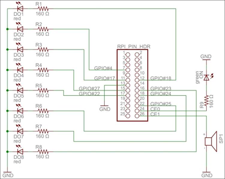
A circuit diagram for the actuator project
Interfacing the hardware
All the hardware interfaces except the alarm output are simple digital outputs. They can be controlled by the DigitalOutput class. The alarm output will control the speaker through a square wave signal that will be output on GPIO pin 7 using the SoftwarePwm class, which outputs a pulse-width-modulated square signal on one or more digital outputs. The SoftwarePwm class will only be created when the output is active. When not active, the pin will be left as a digital input.
The declarations look as follows:
private static DigitalOutput executionLed =
new DigitalOutput (8, true);
private static SoftwarePwm alarmOutput = null;
private static Thread alarmThread = null;
private static DigitalOutput[] digitalOutputs = new DigitalOutput[]
{
new DigitalOutput (18, false),
new DigitalOutput (4, false),
new DigitalOutput (17, false),
new DigitalOutput (27, false),// pin 21 on RaspberryPi R1
new DigitalOutput (22, false),
new DigitalOutput (25, false),
new DigitalOutput (24, false),
new DigitalOutput (23, false)
};
Digital output is controlled using the objects in the digitalOutputs array directly. The alarm is controlled by calling the AlarmOn() and AlarmOff()methods.
Tip
Appendix D, Control, details how these hardware interfaces are used to perform control operations.
Creating a controller
We have a sensor that provides sensing and an actuator that provides actuating. But none have any intelligence yet. The controller application provides intelligence to the network. It will consume data from the sensor, then draw logical conclusions and use the actuator to inform the world of its conclusions.
The controller we create will read the ambient light and motion detection provided by the sensor. If it is dark and there exists movement, the controller will sound the alarm. The controller will also use the LEDs of the controller to display how much light is being reported.
Tip
Of the three applications we have presented thus far, this application is the simplest to implement since it does not publish any information that needs to be protected. Instead, it uses two other applications through the interfaces they have published. The project does not use any particular hardware either.
Representing sensor values
The first step toward creating a controller is to access sensors from where relevant data can be retrieved. We will duplicate sensor data into these private member variables:
private static bool motion = false;
private static double lightPercent = 0;
private static bool hasValues = false;
In the following chapter, we will show you different methods to populate these variables with values by using different communication protocols. Here, we will simply assume the variables have been populated by the correct sensor values.
Parsing sensor data
We get help from Clayster.Library.IoT.SensorData to parse data in XML format, generated by the sensor data export we discussed earlier. So, all we need to do is loop through the fields that are received and extract the relevant information as follows. We return a Boolean value that would indicate whether the field values read were different from the previous ones:
private static bool UpdateFields(XmlDocument Xml)
{
FieldBoolean Boolean;
FieldNumeric Numeric;
bool Updated = false;
foreach (Field F in Import.Parse(Xml))
{
if(F.FieldName == "Motion" && (Boolean = F as FieldBoolean) != null)
{
if(!hasValues || motion != Boolean.Value)
{
motion = Boolean.Value;
Updated = true;
}
} else if(F.FieldName == "Light" && (Numeric = F as FieldNumeric) != null && Numeric.Unit == "%")
{
if(!hasValues || lightPercent != Numeric.Value)
{
lightPercent = Numeric.Value;
Updated = true;
}
}
}
return Updated;
}
Calculating control states
The controller needs to calculate which LEDs to light along with the state of the alarm output based on the values received by the sensor. The controlling of the actuator can be done from a separate thread so that communication with the actuator does not affect the communication with the sensor, and the other way around. Communication between the main thread that is interacting with the sensor and the control thread is done using two AutoResetEvent objects and a couple of control state variables:
private static AutoResetEvent updateLeds = new AutoResetEvent(false);
private static AutoResetEvent updateAlarm = new AutoResetEvent(false);
private static int lastLedMask = -1;
private static bool? lastAlarm = null;
private static object synchObject = new object();
We have eight LEDs to control. We will turn them off if the sensor reports 0 percent light and light them all if the sensor reports 100 percent light. The control action we will use takes a byte where each LED is represented by a bit. The alarm is to be sounded when there is less than 20 percent light reported and the motion is detected. The calculations are done as follows:
private static void CheckControlRules()
{
int NrLeds = (int)System.Math.Round((8 * lightPercent) / 100);
int LedMask = 0;
int i = 1;
bool Alarm;
while(NrLeds > 0)
{
NrLeds--;
LedMask |= i;
i <<= 1;
}
Alarm = lightPercent < 20 && motion;
We then compare these results with the previous ones to see whether we need to inform the control thread to send control commands:
lock(synchObject)
{
if(LedMask != lastLedMask)
{
lastLedMask = LedMask;
updateLeds.Set();
}
if (!lastAlarm.HasValue || lastAlarm.Value != Alarm)
{
lastAlarm = Alarm;
updateAlarm.Set();
}
}
}
Creating a camera
In this book, we will also introduce a camera project. This device will use an infrared camera that will be published in the network, and it will be used by the controller to take pictures when the alarm goes off.
Hardware
For our camera project, we've chosen to use the LinkSprite JPEG infrared color camera instead of the normal Raspberry Camera module or a normal UVC camera. It allows us to take photos during the night and leaves us with two USB slots free for Wi-Fi and keyboard. You can take a look at the essential information about the camera by visiting http://www.linksprite.com/upload/file/1291522825.pdf. Here is a summary of the circuit connections:
· The camera has a serial interface that we can use through the UART available on Raspberry Pi. It has four pins, two of which are reception pin (RX) and transmission pin (TX) and the other two are connected to 5 V and ground GND respectively.
· The RX and TX on the Raspberry Pi pin header are connected to the TX and RX on the camera, respectively. In parallel, we connect the TX and RX lines to a logical inverter. Then, via 240 Ω resistors, we connect them to two LEDs, yellow for TX and green forRX, and then to GND. Since TX and RX are normally high and are drawn low during communication, we need to invert the signals so that the LEDs remain unlit when there is no communication and they blink when communication is happening.
· We also connect four GPIO pins (18, 23, 24, and 25) via 160 Ω resistors to four LEDs and ground to signal the different states in our application. GPIO 18 controls a green LED signal when the camera application is running. GPIO 23 and 24 control yellow LEDs; the first GPIO controls the LED when communication with the camera is being performed, and the second controls the LED when a network request is being handled. GPIO 25 controls a red LED, and it is used to show whether an error has occurred somewhere.
This project can be better understood with the following circuit diagram:
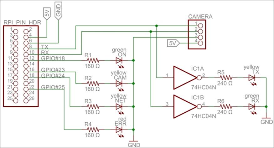
A circuit diagram for the camera project
Tip
For a bill of materials containing components used, see Appendix R, Bill of Materials.
Accessing the serial port on Raspberry Pi
To be able to access the serial port on Raspberry Pi from the code, we must first make sure that the Linux operating system does not use it for other purposes. The serial port is called ttyAMA0 in the operating system, and we need to remove references to it from two operating system files: /boot/cmdline.txt and /etc/inittab. This will disable access to the Raspberry Pi console via the serial port. But we will still be able to access it using SSH or a USB keyboard. From a command prompt, you can edit the first file as follows:
$ sudo nano /boot/cmdline.txt
You need to edit the second file as well, as follows:
$ sudo nano /etc/inittab
Tip
For more detailed information, refer to the http://elinux.org/RPi_Serial_Connection#Preventing_Linux_using_the_serial_port article and read the section on how to prevent Linux from using the serial port.
Interfacing the hardware
To interface the hardware laid out on our prototype board, we will use the Clayster.Library.RaspberryPi library. We control the LEDs using DigitalOutput objects:
private static DigitalOutput executionLed = new DigitalOutput (18, true);
private static DigitalOutput cameraLed = new DigitalOutput (23, false);
private static DigitalOutput networkLed = new DigitalOutput (24, false);
private static DigitalOutput errorLed = new DigitalOutput (25, false);
The LinkSprite camera is controlled by the LinkSpriteJpegColorCamera class in the Clayster.Library.RaspberryPi.Devices.Cameras subnamespace. It uses the Uart class to perform serial communication. Both these classes are available in the downloadable source code:
private static LinkSpriteJpegColorCamera camera = new LinkSpriteJpegColorCamera (LinkSpriteJpegColorCamera.BaudRate.Baud__38400);
Creating persistent default settings
For our camera to work, we need four persistent and configurable default settings: camera resolution, compression level, image encoding, and an identity for our device. To achieve this, we create a DefaultSettings class that we can persist in the object database:
public class DefaultSettings : DBObject
{
private LinkSpriteJpegColorCamera.ImageSize resolution = LinkSpriteJpegColorCamera.ImageSize._320x240;
private byte compressionLevel = 0x36;
private string imageEncoding = "image/jpeg";
private string udn = Guid.NewGuid().ToString();
public DefaultSettings() : base(MainClass.db)
{
}
Adding configurable properties
We publish the camera resolution property as follows. The three possible enumeration values are: ImageSize_160x120, ImageSize_320x240, and ImageSize_640x480. These correspond to the three different resolutions supported by the camera:
[DBDefault (LinkSpriteJpegColorCamera.ImageSize._320x240)]
public LinkSpriteJpegColorCamera.ImageSize Resolution
{
get
{
return this.resolution;
}
set
{
if (this.resolution != value)
{
this.resolution = value;
this.Modified = true;
}
}
}
We publish the compression-level property in a similar manner.
Internally, the camera only supports JPEG-encoding of the pictures that are taken. But in our project, we will add software support for PNG and BMP compression as well. To make things simple and extensible, we choose to store the image-encoding method as a string containing the Internet media type of the encoding scheme implied:
[DBShortStringClipped (false)]
[DBDefault ("image/jpeg")]
public string ImageEncoding
{
get
{
return this.imageEncoding;
}
set
{
if(this.imageEncoding != value)
{
this.imageEncoding = value;
this.Modified = true;
}
}
}
Persisting the settings
We add a method to load any persisted settings from the object database:
public static DefaultSettings LoadSettings()
{
return MainClass.db.FindObjects <DefaultSettings>().GetEarliestCreatedDeleteOthers();
}
}
In our main application, we create a variable to hold our default settings. We make sure to define it as internal using the internal access specifier so that we can access it from other classes in our project:
internal static DefaultSettings defaultSettings;
During application initialization, we load any default settings available from previous executions of the application. If none are found, the default settings are created and initiated to the default values of the corresponding properties, including a new GUID identifying the device instance in the UDN property the UDN property:
defaultSettings = DefaultSettings.LoadSettings();
if(defaultSettings == null)
{
defaultSettings = new DefaultSettings();
defaultSettings.SaveNew();
}
Working with the current settings
To avoid having to reconfigure the camera every time a picture is to be taken, something that is time-consuming, we need to remember what the current settings are and avoid reconfiguring the camera unless new properties are used. These current settings do not need to be persisted since we can reinitialize the camera every time the application is restarted. We declare our current settings parameters as follows:
private static LinkSpriteJpegColorCamera.ImageSize currentResolution;
private static byte currentCompressionRatio;
Initializing the camera
During application initialization, we need to initialize the camera. First, we get the default settings as follows:
Log.Information("Initializing camera.");
try
{
currentResolution = defaultSettings.Resolution;
currentCompressionRatio = defaultSettings.CompressionLevel;
Here, we need to reset the camera and set the default image resolution. After changing the resolution, a new reset of the camera is required. All of this is done on the camera's default baud rate, which is 38,400 baud:
try
{
camera.Reset();// First try @ 38400 baud
camera.SetImageSize(currentResolution);
camera.Reset();
Since image transfer is slow, we then try to set the highest baud rate supported by the camera:
camera.SetBaudRate (LinkSpriteJpegColorCamera.BaudRate.Baud_115200);
camera.Dispose();
camera = new LinkSpriteJpegColorCamera (LinkSpriteJpegColorCamera.BaudRate.Baud_115200);
If the preceding procedure fails, an exception will be thrown. The most probable cause for this to fail, if the hardware is working correctly, is that the application has been restarted and the camera is already working at 115,200 baud. This will be the case duringdevelopment, for instance. In this case, we simply set the camera to 115,200 baud and continue. Here is room for improved error handling, and trying out different options to recover from more complex error conditions and synchronize the current states with the states of the camera:
}
catch(Exception) // If already at 115200 baud.
{
camera.Dispose ();
camera = new LinkSpriteJpegColorCamera (LinkSpriteJpegColorCamera.BaudRate.Baud_115200);
We then set the camera compression rate as follows:
}finally
{
camera.SetCompressionRatio(currentCompressionRatio);
}
If this fails, we log the error to the event log and light our error LED to inform the end user that there is a failure:
}catch(Exception ex)
{
Log.Exception(ex);
errorLed.High();
camera = null;
}
Summary
In this chapter, we presented most of the projects that will be discussed in this book, together with circuit diagrams that show how to connect our hardware components. We also introduced development using C# for Raspberry Pi and presented the basic project structure. Several Clayster libraries were also introduced that help us with common programming tasks such as communication, interoperability, scripting, event logging, interfacing GPIO, and data persistence.
In the next chapter, we will introduce our first communication protocol for the IoT: The Hypertext Transfer Protocol (HTTP).