The Unauthorized Guide to iPhone, iPad, and iPod Repair (2013)
Chapter 17. Replacing the Logic Board and/or Dock Connector
This chapter covers not only logic board replacements, but also Dock connector repair. Why? Well, to save white space in this book, for one reason. Kidding aside, I know that the Dock or Lightning connector in many iDevice models is permanently affixed to the logic board, which means that to replace a Dock connector, you must also replace the logic board.
As usual, I begin this chapter with the theoretical background. Then I provide you with the need-to-know tips and tricks for successfully swapping a logic board and/or Dock connector in your broken iDevice.
About the Logic Board
You can look at the logic board as the “brains” platform of an iDevice. Technically, the central processing unit (CPU) constitutes the “intelligence” of a computer. However the logic board is a component that consists of far more than just the CPU.
If you’ve performed a disassembly of an iPod, iPhone, or iPad then you have seen for yourself that the vast majority of hardware components (including the LCD, digitizer, battery, Wi-Fi antenna, and so forth) terminate to the logic board.
You can see an iPhone logic board in Figure 17.1.
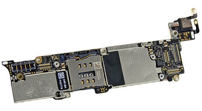
FIGURE 17.1 An iPhone logic board. (Photo courtesy of ifixit.com.)
Much is made in the news when Apple announces a new device as to which processor Apple includes in the logic board. Where exactly is the processor, you may ask? Apple frames the CPU in a slightly larger package called a system-on-a-chip, or SoC.
You can look at an SoC as a sort of mini-computer that generally consists of the main input/output logic of the entire system. For instance, iDevice SoCs include the following:
![]() CPU
CPU
![]() Memory (RAM)
Memory (RAM)
![]() Persistent storage
Persistent storage
![]() Analog-to-digital converter
Analog-to-digital converter
![]() Encryption engine
Encryption engine
![]() Graphics engine (graphics processing unit, or GPU)
Graphics engine (graphics processing unit, or GPU)
In Figure 17.2 you can see a manifest of the iPhone 5 logic board components, courtesy of our friends at iFixit.
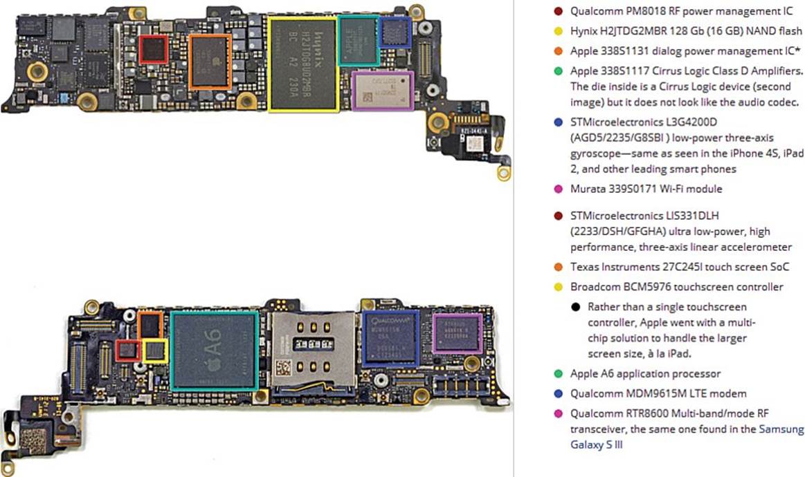
FIGURE 17.2 iPhone 5 SoC components. (Photo courtesy of ifixit.com.)
Note: It Bears Repeating
It’s worth restating that the logic board is effectively the frame, or chassis, for the processor’s SoC and associated components.
The good news about the logic board/system-on-a-chip situation is that all the core iDevice functionality is constrained to a single, user-replaceable part. The bad news is that, depending upon your iDevice, you might need to replace the entire logic board even if only a peripheral part (for instance, the Dock connector) goes bad.
iDevice Connectors
The Apple 30-pin Dock connector descends historically from the laptop docking station connectors that were used 15 to 20 years ago. In point of fact, the Dock connector first appeared in the 2003 iPod. Originally, the iPod cables were FireWire only. Eventually, Apple got the memo that Universal Serial Bus (USB) is the platform-independent standard. Thus, the Dock and even Lightning connectors to this very day employ the USB 2.0 standard. You can read more on the USB subject a bit later.
Note: Pay Attention to Product Names
Recall that you need to pay special attention to product names. Apple refers to the 30-pin Dock connector with a capital D. Please keep this in mind, even though you’re likely to see references to “dock connectors” elsewhere on the Web.
I have not been the biggest fan of the 30-pin Dock connector for the following reasons:
![]() The connector is unidirectional, making proper connection difficult to perform in the dark
The connector is unidirectional, making proper connection difficult to perform in the dark
![]() The connector interface seats inside the iDevice in an unstable, somewhat shaky manner
The connector interface seats inside the iDevice in an unstable, somewhat shaky manner
On the other hand, the 30-pin connector can be used both to charge as well as sync data on supported iDevices. Moreover, the 30-pin connector carries just about any type of video or audio signal. In point of fact, I’ve given several successful presentations by connecting my iPad to a digital projector by means of the Apple 30-pin-to-DVI or 30-pin-to-VGA output adapters.
In 2012, Apple’s long-standing commitment to the 30-pin Dock connector changed both fundamentally and quickly with its announcement of the Lightning interface. The following iDevices support the Lightning connector, and you can rest assured that all future iDevices will use this new connector type as well.
![]() iPhone 5
iPhone 5
![]() iPad mini
iPad mini
![]() iPad 4th generation
iPad 4th generation
![]() iPod touch 5th generation
iPod touch 5th generation
![]() iPod nano 7th generation
iPod nano 7th generation
Figure 17.3 shows the 30-pin and Lightning connectors side by side.
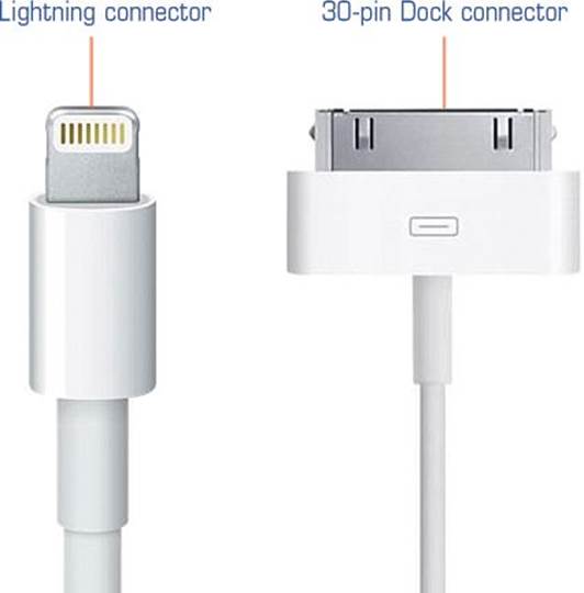
FIGURE 17.3 Side-by-side comparison of the Lightning and 30-pin connectors.
In a nutshell, here is what I like about the Lightning connector:
![]() The Lightning connector is incredibly small and feels good in your hand.
The Lightning connector is incredibly small and feels good in your hand.
![]() The Lightning connector is reversible! No more fumbling in the dark with plugging in your iDevice for overnight charging.
The Lightning connector is reversible! No more fumbling in the dark with plugging in your iDevice for overnight charging.
![]() The Lightning connector seats securely inside your iDevice. The connector head is one encapsulated piece instead of a row of wobbly pins.
The Lightning connector seats securely inside your iDevice. The connector head is one encapsulated piece instead of a row of wobbly pins.
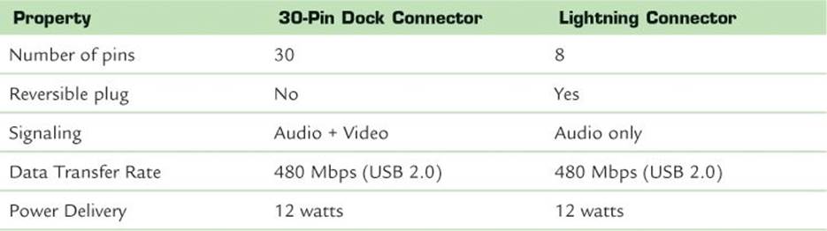
In Table 17.1, I’ve summarized the major properties of the 30-pin Dock and Lightning connectors for easy reference.
TABLE 17.1 30-pin and Lightning Connector Comparison
Two important, additional points to consider with regard to the Lightning connector are
![]() Lightning operates at USB 2.0, not USB 3.0 speeds
Lightning operates at USB 2.0, not USB 3.0 speeds
![]() Lightning has no “video out” capability
Lightning has no “video out” capability
Given that USB 2.0 has a 480 megabits per second (Mbps) transfer rate and USB 3.0 has a 5 gigabits per second (Gbps) transfer rate, it seems strange to me that Apple hasn’t made the Lightning interface work with USB 3.0, or even Apple’s and Intel’s own Thunderbolt interface. Even more puzzling is the fact that USB 3.0 is backward compatible with USB 2.0.
To Apple’s credit, they probably bypassed using micro USB as the interface because micro USB can deliver only 9 watts of power, and iPads need at least 10 watts.
A bit of silver lining here is that you can still use Dock-era chargers with Lightning USB cables in order to charge your iDevices.
As a teacher, I have presented material to my students several times by using my iPad 2 with a trusty Dock-to-DVI or Dock-to-VGA video adapter (shown in 17.4).
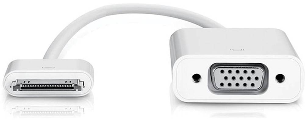
FIGURE 17.4 The 30-pin interface supports video out to a variety of monitor interfaces.
If you can believe it, the Lightning interface (at least as of this writing in early 2013) does not support “video out” signaling. This means you cannot use a Lightning-equipped iDevice to display video on a computer monitor, digital projector, or television screen without (you guessed it) the purchase of yet another adapter.
Apple sells a Lightning-to-HDMI adapter that, at least on paper, enables you to mirror your iDevice display to an HDMI-capable television or monitor. However, the Apple Store reviews on this technology are mixed.
Sadly, those of you who invested heavily in iDevice accessories that include the standard Dock connector will likely spend a pretty penny purchasing signal converters.
For your reference, here is a list of Lightning adapters that were available at the time of this writing. Here is a list of the adapters that are shown in Figure 17.5:
![]() Lightning to 30-pin Adapter (with and without cable)
Lightning to 30-pin Adapter (with and without cable)
![]() Lightning to USB Cable
Lightning to USB Cable
![]() Lightning to Micro USB Adapter
Lightning to Micro USB Adapter
![]() Lightning to Digital AV Adapter
Lightning to Digital AV Adapter
![]() Lightning to VGA Adapter
Lightning to VGA Adapter
![]() Lightning to USB Camera Adapter
Lightning to USB Camera Adapter
![]() Lightning to SD Card Camera Reader
Lightning to SD Card Camera Reader
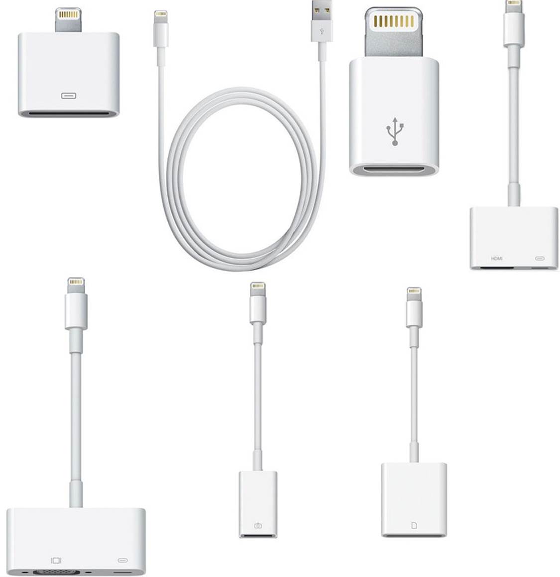
FIGURE 17.5 Apple is more than willing to sell you adapters to get the Lightning interface “talking to” your current Dock-enabled hardware.
Tip: Apple’s Grip Tightens
According to the well-respected technology website Ars Technica (http://is.gd/3WPCaq), Apple included an on-board authentication chip inside the Lightning connector plug that makes is very difficult for iDevice peripheral manufacturers to make their accessories without Apple’s approval.
Repair Advice
You might have the following question: “Given that so much of the iDevice functionality hinges on the logic board, how can I test to verify that a logic board is, indeed, bad?”
The answer to that question is straightforward: Pull the suspected bad logic board from the source device and install it in a known-good device.
Remember that if you want to become a productive iDevice tech, you need to make a substantial investment for tools and parts. Some of these “parts” can be considered known-good iDevices that you can use for diagnostics such as these.
If you put a suspected bad logic board into a known-good iDevice and that device fails to boot then you can state conclusively that you need to replace the logic board on the ailing device. The same “swap” rule applies to the Dock Connector for iDevices that allow the Dock connector to be separated from the logic board.
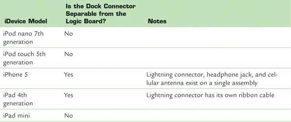
Speaking of Dock connectors, let me provide you with a “cheat sheet” that you can use to instantly determine whether the connector can be replaced on an iDevice independently of the logic board.
TABLE 17.2 Relationship of Dock Connector to the Logic Board on Select iDevices
In my experience, replacing an iDevice logic board is a pretty straightforward operation. The only tough spots are the soldering requirement for certain iDevices, and the difficulty in removing the display assembly on iPads.
Overall, the best advice I can give you for sourcing replacement logic boards is to obtain a vendor referral from a trusted source. For instance, in a recent eBay auction search for an iPhone 4S logic board I obtained results that were priced from $13.50 to more than $200. That price variance is suspect, to say the least.
If you want or need to perform advanced diagnostics on iDevice Dock connectors and logic boards, then you need to use a multimeter. A multimeter is a hardware testing device that measures several electrical properties, including
![]() Resistance
Resistance
![]() Voltage
Voltage
![]() Current
Current
Theoretically, you should be able to use any ol’ multimeter to test iDevice electrical components. However, the good folks at Red Fish Instruments (http://redfishinstruments.com) have developed an iDevice-specific multimeter called the iDVM Multimeter. Figure 17.6 shows you this product.
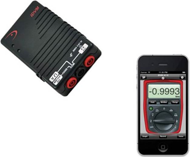
FIGURE 17.6 The Red Fish Instruments iDVM Multimeter.
The iDVM is a combination of hardware and software. The iDVM hardware instrument communicates with your iDevice wirelessly, and reports its data findings to an associated iOS app. Pretty cool, huh?
Tips and Tricks for Logic Board Replacements
Let’s conclude this chapter with some targeted advice concerning things you should watch out for when you attempt a logic board replacement on recent iPhones, iPads, and iPods.
iPhone 5
iPhone 5 (and iPhone 4/4S, for that matter) logic boards are the easiest logic boards to replace in any iOS device. Sure, you have to field-strip the iDevice practically to the bare metal. You also have to remove a large number of microscopic screws. However, you have no glue or solder joints impeding your progress—in iDevice repair, that is a good thing.
The best advice I can give you for iPhone 5 logic board repairs are as follows:
![]() Take all the time you need in re-seating the logic board. We know by now that Apple engineers make use of every square centimeter inside an iPhone chassis. Leaving the logic board the tiniest bit askew—which is to say, not 100 percent flush—will wreak havoc later on in the reassembly, particularly with the display alignment.
Take all the time you need in re-seating the logic board. We know by now that Apple engineers make use of every square centimeter inside an iPhone chassis. Leaving the logic board the tiniest bit askew—which is to say, not 100 percent flush—will wreak havoc later on in the reassembly, particularly with the display alignment.
![]() Be respectful of the interconnect cables and camera connections. Don’t just yank up the logic board from the frame during disassembly in an (understandable) moment of frustration. The interconnect cables are there for a reason, and these connectors, as well as those for the rear-facing camera, need to be seated properly during reassembly to ensure the iDevice will work properly post-reassembly.
Be respectful of the interconnect cables and camera connections. Don’t just yank up the logic board from the frame during disassembly in an (understandable) moment of frustration. The interconnect cables are there for a reason, and these connectors, as well as those for the rear-facing camera, need to be seated properly during reassembly to ensure the iDevice will work properly post-reassembly.
I show you the relationship between the iPhone 5 logic board and the interconnect cables in Figure 17.7.
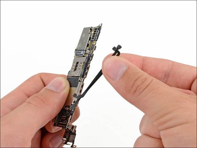
FIGURE 17.7 Treat the rear-facing camera and interconnect cables and connectors with care during a logic board replacement. (Courtesy of ifixit.com.)
iPad 3rd and 4th Generation
Logic board replacements on the 3rd and 4th generation iPads are extraordinarily difficult. As we’ve discussed previously, removing the glass panel/digitizer assembly runs a high risk of shattering the glass.
The best advice I can offer you, besides carefully noting which screws and connectors go with which components, is to stock up on Kapton tape. As you can see in Figure 17.8, Apple uses a copious amount of Kapton tape and adhesive to secure cables and connectors to the logic board and rear case.
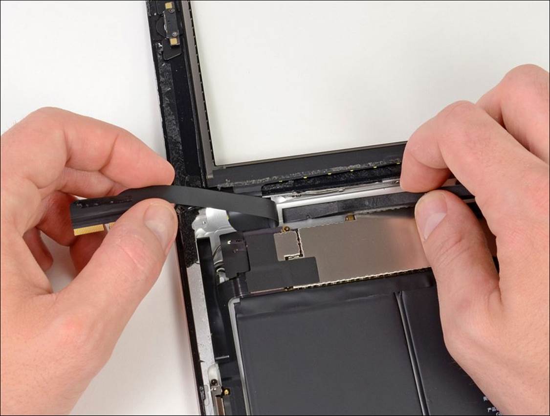
FIGURE 17.8 iPad logic boards are secured with plenty of Kapton tape and adhesive glue. (Photo courtesy of ifixit.com.)
iPad mini
All of the standard precautions that apply to the full-sized iPads apply in turn to the iPad mini. With the mini, however, I advise you to remember that the Lightning connector is soldered to the logic board. This is shown in Figure 17.9.
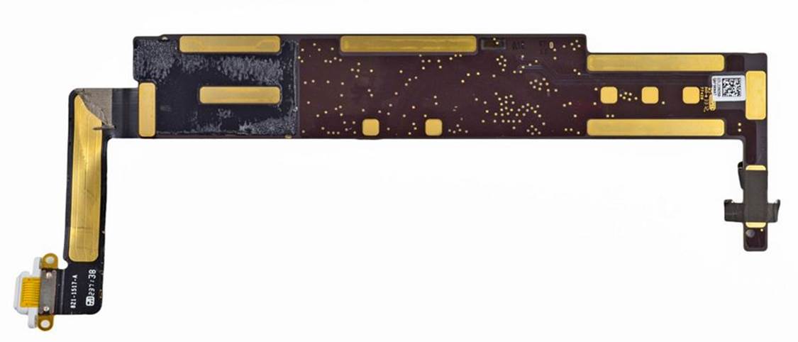
FIGURE 17.9 In the iPad mini, the Lightning connector is soldered to the logic board.
iPod touch 5th Generation
In the iPod touch 5th generation, the logic board, battery, front-facing camera, Lightning connector, speaker, headphone jack, and Home button are all soldered together into an individual assembly. Fun, fun!
Therefore, the biggest disappointment in replacing the logic board on the iPod touch is that you can either:
![]() Buy a replacement logic board assembly, with all connected hardware.
Buy a replacement logic board assembly, with all connected hardware.
![]() Use your soldering equipment to desolder and resolder the existing hardware components to the new logic board.
Use your soldering equipment to desolder and resolder the existing hardware components to the new logic board.
Figure 17.10 shows the removal of the iPod touch 5th generation logic board assembly.
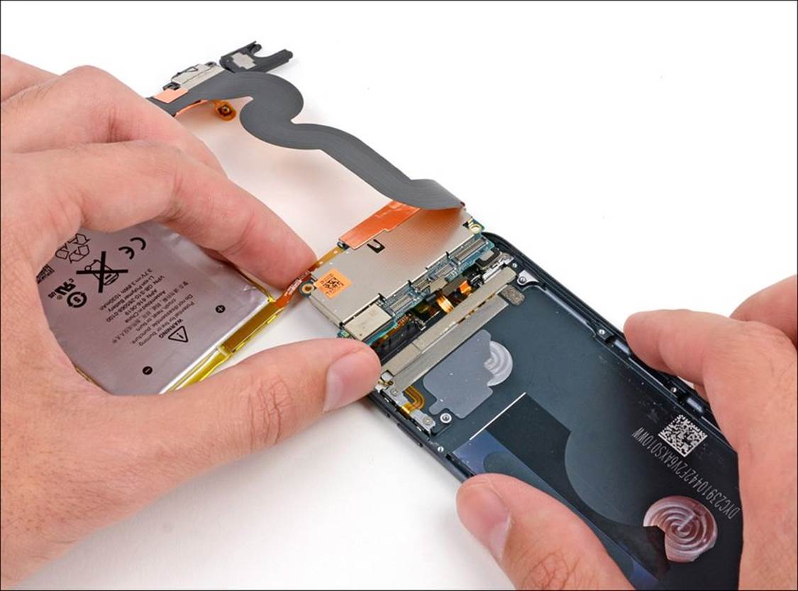
FIGURE 17.10 Several components are soldered to the iPod touch logic board. (Photo courtesy of ifixit.com.)