Blender Cycles: Materials and Textures Cookbook, Third Edition (2015)
Chapter 4. Creating Man-made Materials in Cycles
In this chapter, we will cover the following recipes:
· Creating a generic plastic material
· Creating a Bakelite material
· Creating an expanded polystyrene material
· Creating a clear (glassy) polystyrene material
· Creating a rubber material
· Creating an antique bronze material with procedurals
· Creating a multipurpose metal node group
· Creating a rusty metal material with procedurals
· Creating a wood material with procedurals
Introduction
On most occasions, artificial materials are quite easy to recreate in Cycles.
In the previous chapters we discussed the mechanics of building materials through procedural textures using the Cycles render engine. In this chapter, we'll discuss some artificial materials. Starting with one or two examples of simple materials, such as plastic, we will progress to more complex materials. We'll also take a look at the decayed material shaders and treat them as worn or rusty metals.
Note that in Cycles, it's not actually necessary to add the nodes for the texture mapping coordinates to any shader network. This is because, by default and if not otherwise specified, Cycles automatically uses the Generated mapping coordinates for procedural textures and any existing UV coordinate layer for the image textures.
Anyway, I think it's a good habit to add both the Texture Coordinate and the Mapping nodes to all the materials to permit easy reutilization of the shaders on different objects with different mapping options, scales, and locations.
Creating a generic plastic material
In this recipe, we will create a generic plastic shader and add slight granularity (optional) to the surface, as shown in the following screenshot:
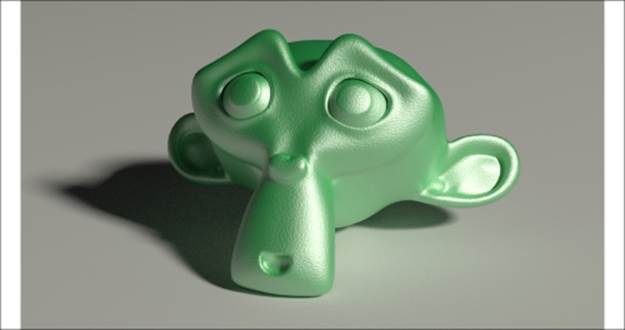
The generic plastic material as it appears in the final rendering
Getting ready...
Start Blender and load the 9931OS_Suzanne_start.blend file. This is a prepared scene, with Suzanne (the monkey head primitive that is Blender's mascot) leaning on a white Plane, a Camera, a mesh-light emitting slightly yellowish light, and a low-intensity gray World.
Note
We'll use a lot this file as starting point for several of our recipes.
How to do it...
Now we will go straight to creation of the material, so follow these steps:
1. Select Suzanne and click on New in the Material window under the Properties panel or in the Node Editor toolbar. Rename the material Plastic_Green_Soft.
2. Set the Viewport Shading mode of the Camera view to Rendered by moving the mouse into the 3D view and pressing Shift + Z.
3. In the Material window under the Properties panel, switch the Diffuse BSDF shader with a Mix Shader node, and in the first Shader slot, select a Diffuse BSDF shader. In the second Shader slot, select a Glossy BSDF node.
4. Change the Diffuse BSDF color to bright green (change the values of R to 0.040, G to 0.800, and B to 0.190) and the Glossy BSDF shader's Roughness value to 0.300.
5. Press Shift + D to duplicate the Mix Shader node, and paste it between the first Mix Shader node and the Material Output node. Set the Fac value to 0.100.
6. Duplicate the Glossy BSDF node and connect its output to the second input socket of the second Mix Shader node. Set its Roughness value to 0.500, as shown in the following screenshot:
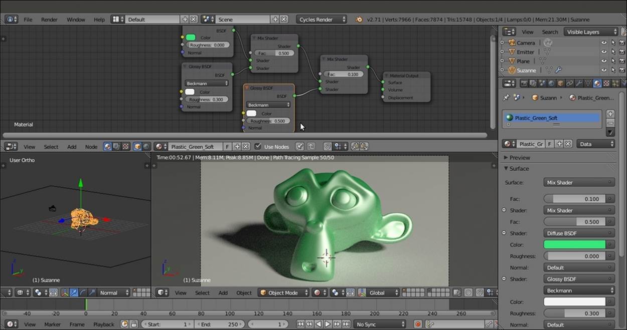
A screenshot of the entire Blender interface with the basic shader nodes in the Node Editor window at the top
7. Add a Noise Texture node (press Shift + A and navigate to Texture | Noise Texture), a Texture Coordinate node (press Shift + A and navigate to Input | Texture Coordinate), and a Mapping node (press Shift + A and navigate to Vector | Mapping).
8. Connect the Object output of the Texture Coordinate node to the Vector input of the Mapping node, and the output of this node to the input of the Noise Texture node.
9. Set the Noise Texture node's Scale value to 50.000. Add a Math node (press Shift + A and navigate to Converter | Math). Connect the Noise Texture node's Fac output to the first Value input of the Math node. Set the Math node's Operation to Multiplyand second Value to 0.050. Connect its Value output to the Displacement input socket of the Material Output node, as shown in the following screenshot:
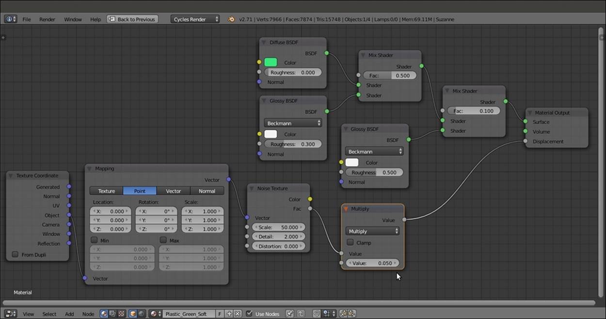
The very simple bump effect added to the shader nodes by connecting the output of the Noise Texture node to the Displacement input socket of the Material Output node
10. Save the file as Plastic_soft.blend.
How it works...
This is one of the simplest materials you can build in Cycles. It consists of a colored Diffuse BSDF component mixed at 50 percent with a white Glossy BSDF shader and another low Glossy BSDF shader to make the specular effect more diffused. A tiny Noise Texture node, connected directly to the Displacement input of the Material Output node, adds a slightly dotted bump effect to the whole material, as if it is some kind of industrial plastic used for toys.
Creating a Bakelite material
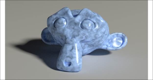
Bakelite is a very common type of plastic and can be found in a lot of different colors and patterns. In this recipe, we will create the black type (which was once really common), as shown in this screenshot:
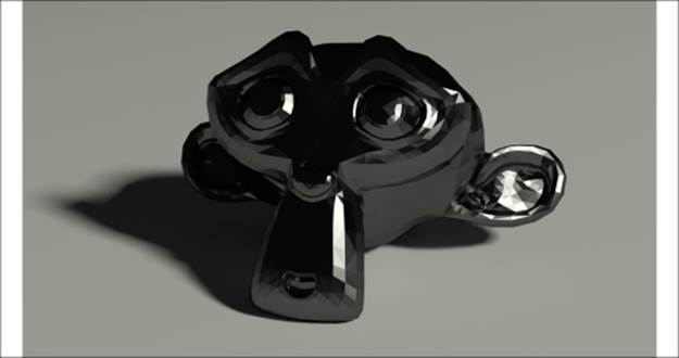
The black Bakelite material as it appears in the final rendering
Getting ready...
Start Blender and load the 9931OS_Suzanne_start.blend file again:
1. With the mouse arrow in the Camera view, press the T key. Select the Suzanne mesh. Go to the Tools tab under the Tool Shelf panel on the left. Select Flat under Shading. Press T again to close the Tool Shelf panel.
2. Go to the Object modifiers window in the Properties panel. Expand the Subdivision Surface modifier panel and set the levels both for View and Render to 1.
How to do it...
Now we are going to create the material by performing the following steps:
1. Go to the Material window and click on New (or do this as usual, in the Node Editor toolbar). Rename the material Plastic_Bakelite_Black.
2. Set the Viewport Shading mode of the Camera view to Rendered.
3. Switch the Diffuse BSDF shader with a Mix Shader node, and in the first Shader slot, select a Diffuse BSDF shader. In the second Shader slot, select a Glossy BSDF node.
4. Change the Diffuse BSDF color to pure black and the Glossy BSDF shader color to light gray (RGB to 0.253). Set the Roughness value of the Glossy BSDF shader to 0.100 and the Fac value of the Mix Shader node to 0.800.
5. Press Shift + D to duplicate the Mix Shader node, and paste it between the Glossy BSDF shader and the first Mix Shader node.
6. With the mouse arrow in the Node Editor window, press N. Select the first Mix Shader node, and in the Label slot in the Active Node panel on the right, write Mix Shader1. Select the second Mix Shader node, and in the Label slot, write Mix Shader2.
7. Add an Anisotropic BSDF shader (press Shift + A and navigate to Shader | Anisotropic BSDF) and connect its output to the second input socket of the Mix Shader2 node.
8. Set the Mix Shader2 node's Fac value to 0.500. Set the Anisotropic BSDF node's color to light gray, and set the same color for the Glossy BSDF shader (that is, RGB to 0.253). Set the Glossy BSDF shader's Roughness value to 0.100 and Rotation to0.500 as shown in the following screenshot:
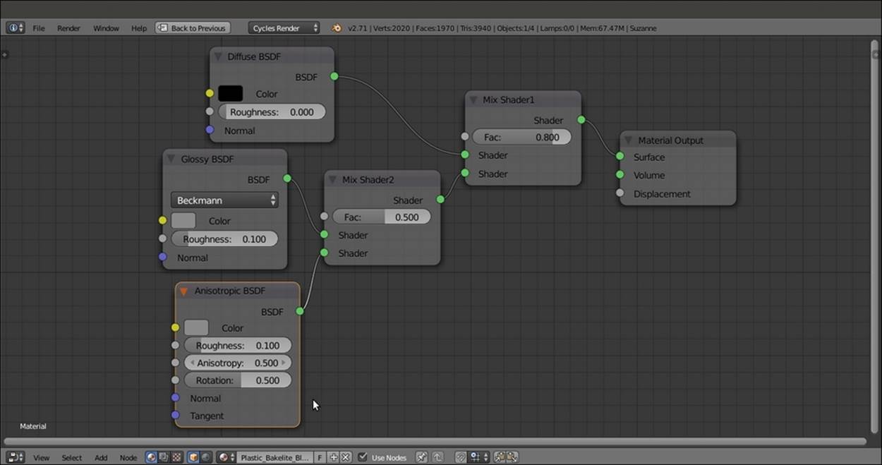
The simple shader network for the basic Bakelite material
9. Save the file as Plastic_Bakelite.blend.
How it works...
Basically, we made the same kind of material as the green plastic material, but this time, we enhanced the reflectivity (mirror) by lowering the Roughness value. We also added an Anisotropic BSDF specularity effect with the same roughness and color as those for the Glossy BSDF shader. The Rotation value of the Anisotropic BSDF shader sets the flow of the highlights on the mesh. The direction of the specularity rotates as this value increases from 0.000 to 1.000.
Anisotropy is a method of enhancing image quality of textures on surfaces that are far away and steeply angled with respect to the point of view. An anisotropic surface will change in appearance as it rotates about its geometric normal.
There's more...
Starting from the black material, let's now try to make a differently processed Bakelite material, as shown in the following screenshot:
A different type of Bakelite
First, we'll make a node group of the Bakelite material by performing the following steps:
1. Click on the material name and rename it Plastic_Bakelite2. Then save the file as Plastic_Bakelite2.blend.
2. Select the Diffuse BSDF, Glossy BSDF, Anisotropic BSDF, and two Mix Shader nodes and press Ctrl + G to make a group.
3. Click and drag the Diffuse BSDF node's Color socket into the empty socket of the Group Input node. Drag the Fac socket of the Mix Shader2 node, and in the Interface subpanel of the Properties panel of the Node Editor window, rename it Aniso. This will drive the influence of the anisotropic shader on the glossy shader. Click and drag the Fac socket of the Mix Shader1 node to the empty socket of Group Input node. Rename it Spec. This will drive the amount of final specularity of the shader. Here is a screenshot of the creation of the Bakelite node group for your reference:
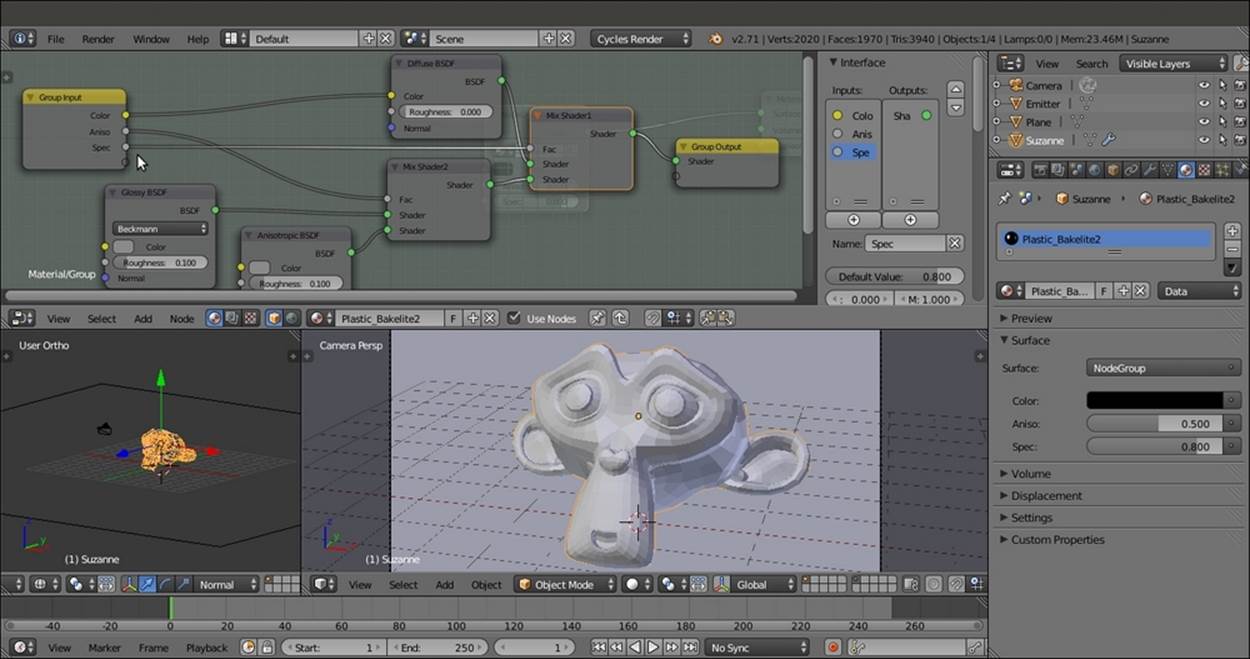
The creation of the Bakelite node group
4. Press Tab to close the group. Rename it Bakelite.
Now we'll add the nodes needed to create the differently colored material that we decided at the beginning of this section:
1. In the Node Editor window, add the following nodes in linear sequence from left to right: a Texture Coordinate node (press Shift + A and navigate to Input | Texture Coordinate), a Mapping node (press Shift + A and navigate to Vector | Mapping), a Noise Texture node (press Shift + A and navigate to Texture | Noise Texture), a ColorRamp node (press Shift + A and navigate to Converter | ColorRamp), and a MixRGB node (press Shift + A and navigate to Color | MixRGB).
2. Connect the Object output of the Texture Coordinate node to the Vector input of the Mapping node, and the output of this node to the input of the Noise Texture node. Connect the Color output of the Noise Texture node to the ColorRamp input socket, and the Color output of the ColorRamp node to the Color1 input socket of the MixRGB node. Connect the Color output of the MixRGB node to the Color input of the Bakelite node group.
3. Set the Noise Texture node's Scale to 4.000, Detail to 4.200, and Distortion to 1.700.
4. Set the ColorRamp node's Interpolation to B-Spline. Move the black color marker to position 0.277 and the white color marker to 0.686.
5. Set MixRGB node's Blend Type to Divide (but remember to experiment with the other types as well) and the Fac value to 0.600. Change the Color2 values of R to 0.799, G to 0.442, and B to 0.220.
6. In the Bakelite node group interface, set the Spec value to 0.300, as shown in the following screenshot:
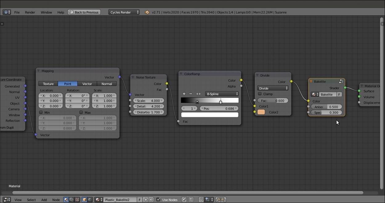
Adding texture details to the Bakelite node group
7. You can also smooth the Suzanne mesh in the Tool Shelf panel (press T) and increase the Subdivision levels of the Subdivision Surface modifier to 2.
8. Save the file.
Creating an expanded polystyrene material
In this recipe, we will create a classic white expanded polystyrene material, as shown in this screenshot:
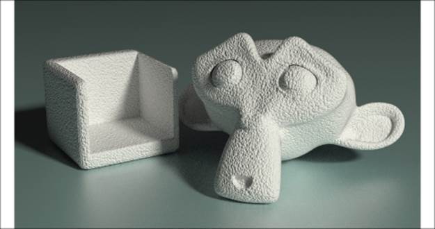
The white expanded polystyrene material as it appears in the final rendering
Getting ready...
First, let's prepare the scene:
1. Start Blender and load the 9931OS_Suzanne_start.blend file. Add a Cube primitive to the scene and place it leaning on the Plane, close to Suzanne. Move it upwards by 1 Blender unit.
2. With the mouse arrow in the Camera view, press Shift + F to enter Walk Mode (in this mode, you can press the W key to go forward, press S to go back, move the mouse to decide the direction, and click or press Enter to confirm). Adjust the Camera position so as to center the two objects in the frame.
3. Select the Cube object and go to the Object modifiers window. Assign a Boolean modifier.
4. Press Shift + D to duplicate the Cube, and move it a bit upward (press G, then press Z, enter .4, and press Enter). Reselect the first Cube, and in the Object field of the Boolean modifier panel, select the second Cube (Cube.001). Set Operation toDifference. Go to Edit Mode and scale all the vertices a bit larger on the x and y axes (press S, then press Shift + Z, enter 1.200, and press Enter).
5. Exit Edit Mode and reselect Cube.001. Move it a bit on the x axis (press G, then press X, enter .4, and press Enter).
6. Go to the Object window and set Maximum Draw Type to Wire. Then go to the Ray Visibility subpanel (usually at the bottom) and uncheck all the items. This way, Cube.001 becomes visible in the 3D view, but is not yet rendered in the preview.
7. Just to be sure that the second cube is not visible (the previous step should be enough for the final rendering), go to Outliner and click on the camera icon to the right of the Cube.001 item.
8. Select the first Cube and assign a Bevel modifier. Set the Width value to 0.0200. Move it higher in the stack of modifiers and place it before the Boolean modifier.
9. Assign a Subdivision Surface modifier and set both the Subdivisions levels to 2. Check the Optimal Display item and move it higher in the stack. Place it before the Boolean modifier but after the Bevel modifier.
10. Press T to call the Tool Shelf panel. Set the Cube shading to Smooth.
11. Press Shift, select both Cube and the Cube.001 objects, and rotate them on z axis towards the Camera (press R, then press Z, enter -40, and then press Enter).
12. Press T to close the Tool Shelf panel. The following screenshot shows the process of building the box object:
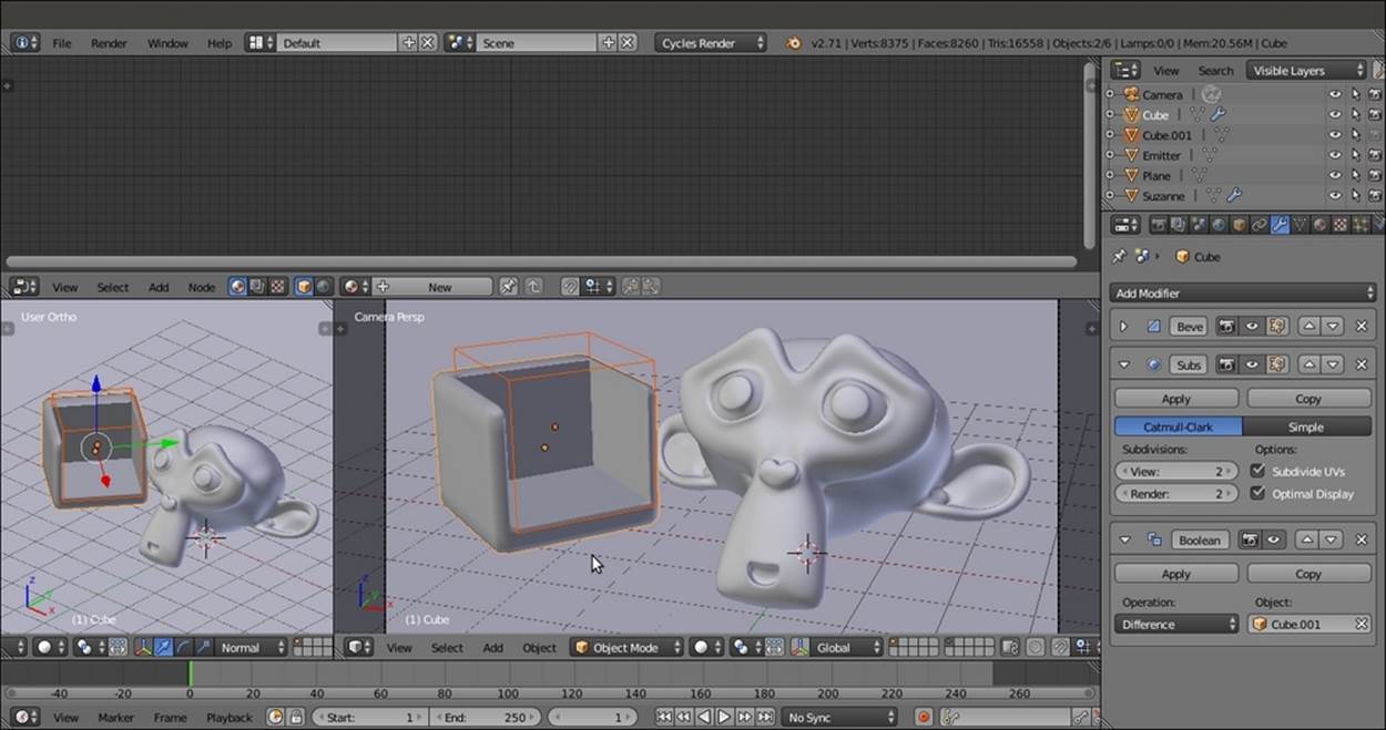
Building the box object by a Boolean modifier
13. Select the Plane object, and in the Material window, switch the Diffuse BSDF shader with a Mix Shader node. Then, in the Shader slots, select a Diffuse BSDF node and a Glossy BSDF shader node. Add a Layer Weight node (press Shift + A and navigate to Input | Layer Weight) and connect the Facing output to the Fac input socket of the Mix Shader node. Set the color of the Diffuse BSDF node as follows: R to 0.530, G to 0.800, and B to 0.800.
How to do it...
Now we are going to create the material by performing the following steps:
1. Select Suzanne and click on New in the Material window under the Properties panel or in the Node Editor toolbar. Rename the material Plastic_expanded_polystyrene.
2. Switch the Diffuse BSDF shader with a Mix Shader node, and in the first Shader slot, select a Diffuse BSDF shader. In the second Shader slot, select a Glossy BSDF node.
3. Set the Diffuse BSDF shader color and the Glossy shader color to pure white. Set the Roughness value of the Glossy BSDF shader to 0.600. Add a Fresnel node (press Shift + A and navigate to Input | Fresnel). Connect its output to the Fac input socket of the Mix Shader node. Set the IOR value to 1.550.
4. Add a Voronoi Texture node (press Shift + A and navigate to Texture | Voronoi Texture), a Texture Coordinate node (press Shift + A and navigate to Input | Texture Coordinate), and a Mapping node (press Shift + A and navigate to Vector | Mapping).
5. Connect the Object output of the Texture Coordinate node to the Vector input of the Mapping node, and the output of this node to the Vector input of the Voronoi Texture node.
6. Set the Voronoi Texture node's Scale value to 25.000. Add a Bump node (press Shift + A and navigate to Vector | Bump). Connect the Fac output of the Voronoi Texture node to the Height input socket of the Bump node, and the output of this node to theNormal input sockets of the Diffuse BSDF and Glossy BSDF shader nodes.
7. Check the Invert item on the Bump node and set the Strength value to 0.500, as shown in the following screenshot:
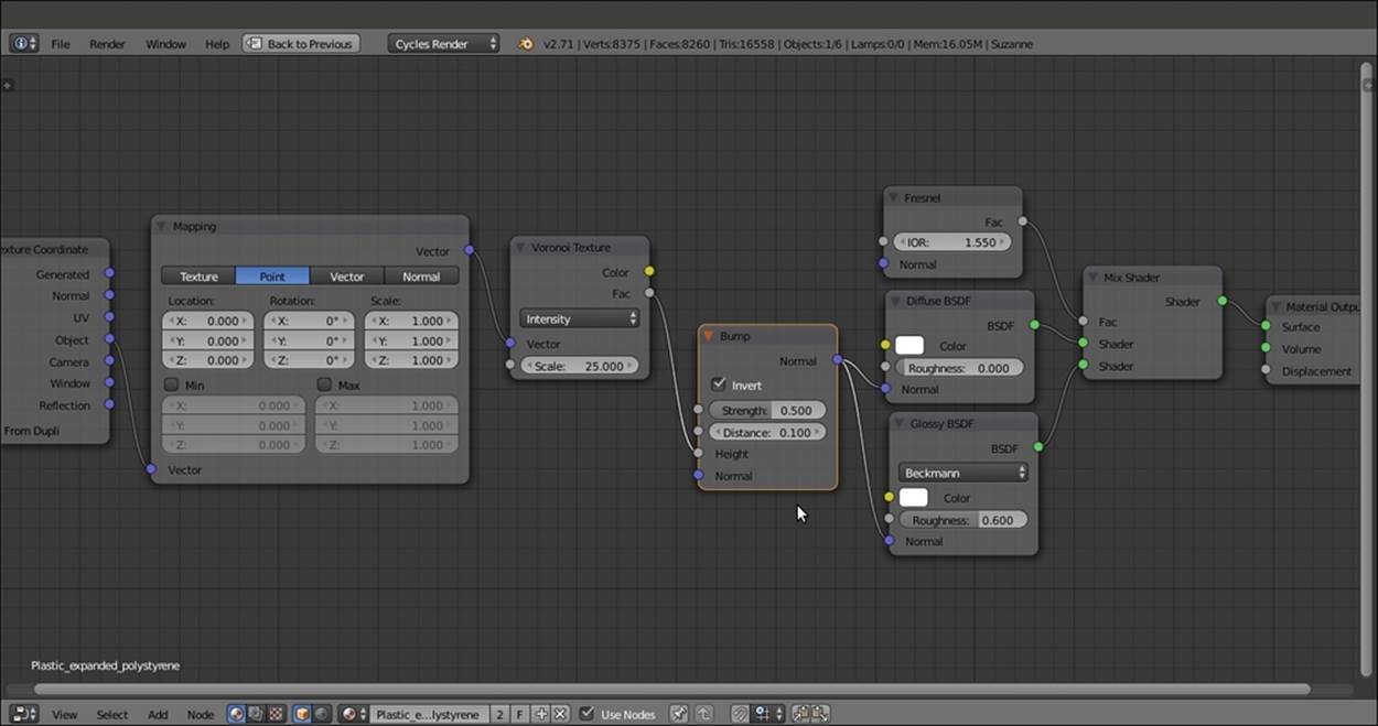
The white expanded polystyrene material network
8. Press Shift and select the Cube object and Suzanne. Then press Ctrl + L, and in the Make Links pop-up menu, select the Material item to assign the material of the active object to the other object.
9. Save the file as Plastic_expanded_polystyrene.blend.
How it works...
You have probably noticed that this recipe is simply a variation of the generic plastic shader. We changed the color to white, and instead of Noise Texture, we used a Voronoi Texture node with a different scale to add the typical polystyrene pattern. Then, by increasing the Roughness value of the Glossy BSDF shader, we made the specularity more diffused.
Creating a clear (glassy) polystyrene material
In this recipe, we will create a glassy polystyrene material (which you find on the body of ballpoint pens), as shown in the following screenshot:
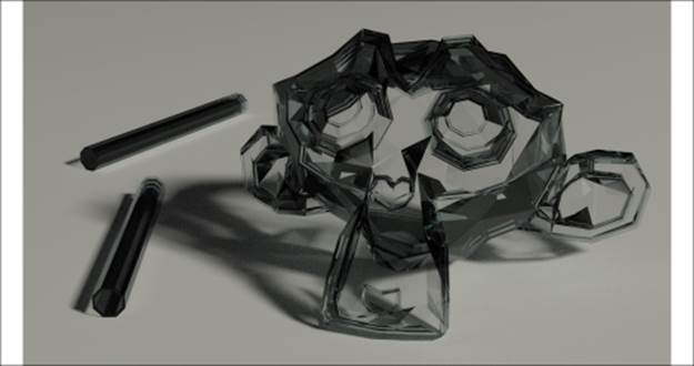
The glassy polystyrene material as it appears in the final rendering
Getting ready...
First, we need the usual preparation:
1. Start Blender and load the 9931OS_Suzanne_start.blend file.
2. Select the Suzanne mesh and press T. In the Tool Shelf panel on the left side, select Flat under Shading. Press T again to close the Tool Shelf panel.
3. Go to the Object modifiers window in the Properties panel and delete the Subdivision Surface modifier. Add a Solidify modifier and set the Thickness value to 0.0350. Add a Bevel modifier and set the Width value to 0.0050. Uncheck the Clamp Overlapitem.
How to do it...
Now we are going to create the material by performing the following steps:
1. Go to the Material window and click on New (or as usual, go to the Node Editor toolbar). Rename the material Plastic_clear_polystyrene.
2. Set the Viewport Shading mode of the Camera view to Rendered.
3. Switch the Diffuse BSDF shader with a Mix Shader node, and in the first Shader slot, select a Mix Shader node again. In the second Shader slot, select a Glass BSDF node. Set its IOR value to 1.460. Change the values of R to 0.688, G to 0.758, and B to0.758.
4. Go to the second Mix Shader node, and in its first Shader slot, select a Transparent BSDF. In the second Shader slot, select a Glossy BSDF node. Change the Glossy BSDF node color values for R to 0.688, G to 0.758, and B to 0.758. Change theRoughness value to 0.010.
5. Add a Fresnel node (press Shift + A and navigate to Input | Fresnel) and connect it to the Fac input sockets of both the Mix Shader nodes. Set the IOR value to 1.460, as shown in the following screenshot:
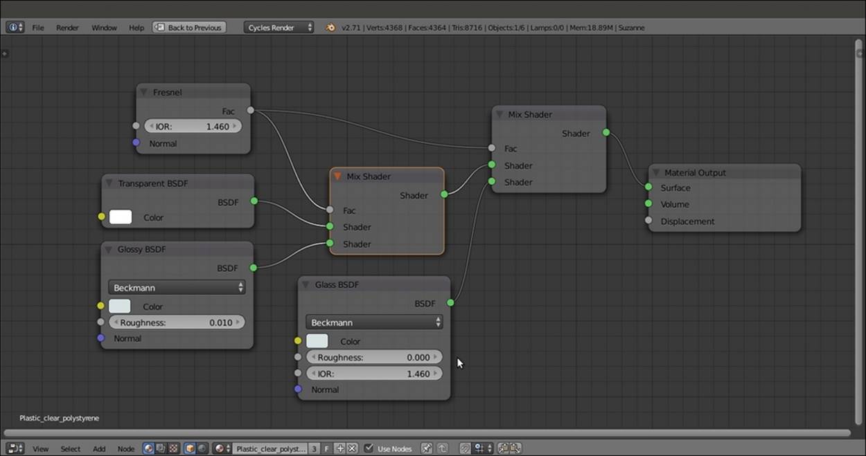
The completed network for the glassy polystyrene material
6. Save the file as Plastic_clear_polystyrene.blend.
Creating a rubber material
In this recipe, we will create a generic rubber shader, as shown in this screenshot:
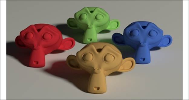
The rubber material as it appears in the final rendering
Getting ready...
Start Blender and load the 9931OS_Suzanne_start.blend file.
How to do it...
Now we are going to create the material by performing the following steps:
1. Click on New in the Material window under the Properties panel or in the Node Editor toolbar. Rename the material Rubber.
2. With the mouse arrow in the Camera view, press Shift + Z to set it to Rendered mode.
3. Switch the Diffuse BSDF shader with a Mix Shader node, and in the second Shader slot, select a Glossy BSDF node. In the first Shader slot, select a new Mix Shader node. Set the Glossy BSDF node's Roughness value to 0.350.
4. Go to the second Mix Shader node, and in the first Shader slot, select a Diffuse BSDF node. In the second Shader slot, select a Velvet BSDF node. Set the Velvet BSDF shader node's Sigma value to 0.600.
5. Add a Fresnel node (press Shift + A and navigate to Input | Fresnel) and connect it to the Fac input of both the Mix Shader nodes. Set the IOR value to 1.519, as shown in the following screenshot:
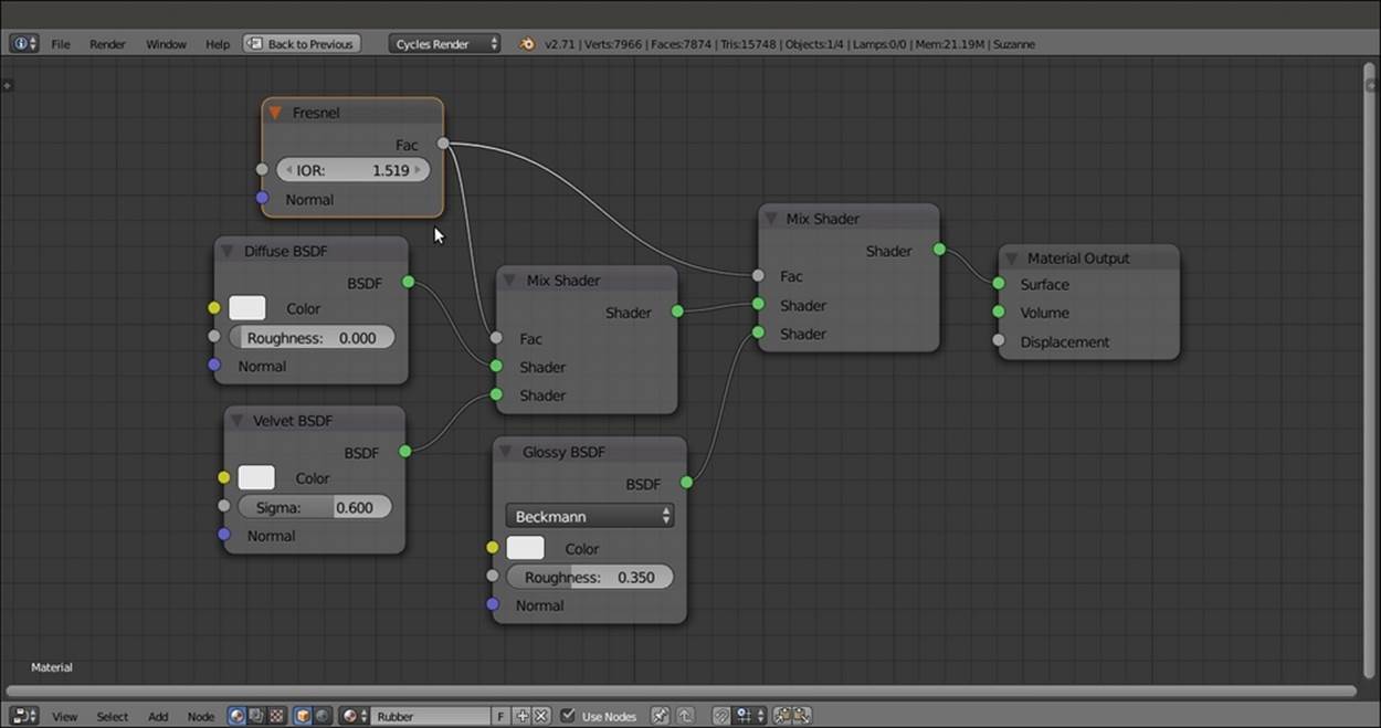
The basic shader network
6. Add a Texture Coordinate node (press Shift + A and navigate to Input | Texture Coordinate), a Mapping node (press Shift + A and navigate to Vector | Mapping), a Voronoi Texture node, and a Noise Texture node (press Shift + A and navigate toTexture | Voronoi Texture, do the same to add Noise Texture node).
7. Connect the Object output of the Texture Coordinate node to the Vector input of the Mapping node, and the latter's output to the Vector input sockets of the two texture nodes.
8. Set the Voronoi Texture node's Coloring to Cells and the Scale value to 350.000. Set the Noise Texture node's Scale value to 450.000 and Detail to 5.000.
9. Add two Math nodes (press Shift + A and navigate to Converter | Math). Set the Operation of the second node to Multiply. Connect the Fac output of the Voronoi Texture node to the first Value input socket of the Add-Math node. Connect the Fac output of the Noise Texture node to the second Value input socket of the Add-Math node.
10. Connect the Add-Math node output to the first Value input socket of the Multiply-Math node. Set second Value to 0.060 and connect the output to the Displacement input socket of the Material Output node, as shown in the following screenshot:
The slight bump effect added to the network
11. Add a MixRGB node (press Shift + A and navigate to Color | MixRGB) and move it close to the Voronoi Texture node. Set the Blend Type to Multiply. Connect the Voronoi Texture node's Color output to the Color2 input socket of the Multiply-MixRGBnode. Then connect the Color output of this node to the Color input sockets of the Diffuse BSDF, Velvet BSDF, and Glossy BSDF shaders.
12. Add an RGB node (press Shift + A and navigate to Input | RGB) and connect it to the Color1 input socket of the Multiply-MixRGB node, as shown in this screenshot:
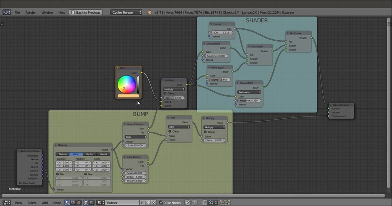
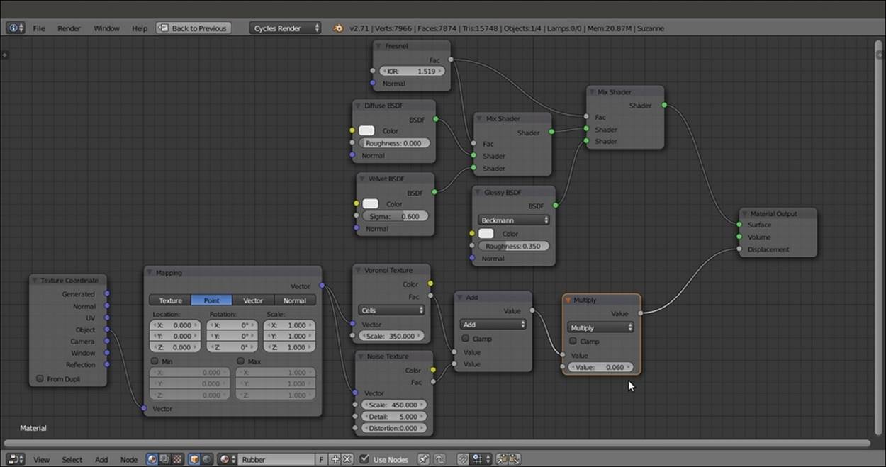
The overall view of the network
13. Save the file as Rubber.blend.
How it works...
We built the shader in steps 1 to 5. We added a slight bump effect in steps 6 to 10. In the last two steps, we just added the RGB node, a control used to set the color of the material.
Creating an antique bronze material with procedurals
In this recipe, we will create a bronze shader that looks similar to a ruined, corroded, and antique statue, as shown in the following screenshot:
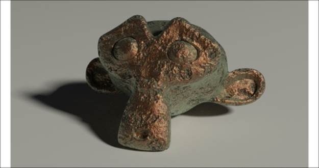
The antique bronze material as it appears in the final rendering when assigned to the poor Suzanne mesh!
Getting ready...
Start Blender and load the 9931OS_Suzanne_start.blend file. Then perform the following steps:
1. With Suzanne selected, click on the Object Mode button in the Camera view toolbar. Choose Vertex Paint.
2. Click on the Paint item in the toolbar and select Dirty Vertex Colors, the first option at the top. Then press T, and in the Option panel at the bottom of the Tool Shelf panel, set Blur Strength to 0.01 and Dirt Angle to 90. Check the Dirt Only item, as shown in this screenshot:
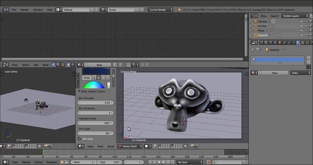
The Dirty Vertex Colors setting and the effect on the Suzanne mesh
3. Go to the Object data window under the Properties panel. Double-click on the Col item in the Vertex Colors subpanel and rename it V_col.
4. Return in Object Mode and press T to close the Tool Shelf tabs.
5. Save the file as 9931OS_Suzanne_vcol.blend. We will use this file for other recipes.
How to do it...
Now we are going to create the material by performing the following steps:
1. First, save the file as Bronze_antique.blend.
2. Click on New in the Material window under the Properties panel or in the Node Editor toolbar. Rename the material Bronze_antique.
3. In the Material window, switch the Diffuse BSDF shader with a Mix Shader node, and in the first Shader slot, select a Diffuse BSDF shader. In the second Shader slot, select a Glossy BSDF node. Set the Diffuse BSDF shader node's Roughness value to1.000 and the Glossy BSDF node's Roughness value to 0.300.
4. Now add a Layer Weight node (press Shift + A and navigate to Input | Layer Weight), a ColorRamp node (press Shift + A and navigate to Converter | ColorRamp), and a MixRGB node (press Shift + A and navigate to Color | MixRGB). In the Propertiespanel of the Node Editor window (press N to make it appear), label the ColorRamp node as ColorRamp1. Set its Interpolation mode to B-Spline.
5. Connect the Facing output of the Layer Weight node to the Fac input of the ColorRamp1 node, and its Color output to the Fac input socket of the MixRGB node.
6. Set the Color1 value of the MixRGB node as R to 0.771, G to 1.000, and B to 0.848. Set the Color2 values as R to 0.222, G to 0.013, and B to 0.000.
7. Add an Invert node (press Shift + A and navigate to Color | Invert). Paste it between the ColorRamp1 and the MixRGB nodes'.
8. Press Shift + D to duplicate the MixRGB node, and set Blend Type to Burn. Set the Fac value to 0.090. Connect the Mix-MixRGB node's Color output to the Color1 input socket of the Burn-MixRGB node.
9. Press Shift + D to duplicate the MixRGB node again. Set the Blend Type to Overlay and the Fac value to 0.200. Connect its Color output to both the Color input sockets of the Diffuse BSDF and Glossy BSDF shaders. Now connect the Color output of theBurn-MixRGB node to the Color1 input socket of the Overlay-MixRGB node, as shown in the following screenshot:
The shader part of the material
10. Add an Attribute node (press Shift + A and navigate to Input | Attribute). Select and press Shift + D to duplicate the ColorRamp and the Invert nodes. Label them as ColorRamp2 and Invert2 , respectively, and move them close to the Attribute node.
11. Write the name of the Vertex Color layer, V_col, in the Name slot of the Attribute node. Then connect its Color output to the Fac input of the ColorRamp2 node. Move the white color stop to position 0.485.
12. Connect the Color output of the ColorRamp node to the Color input of the Invert2 node, then connect the Color output of the Invert2 node to the Fac input socket of the Mix Shader node, as shown in the following screenshot:
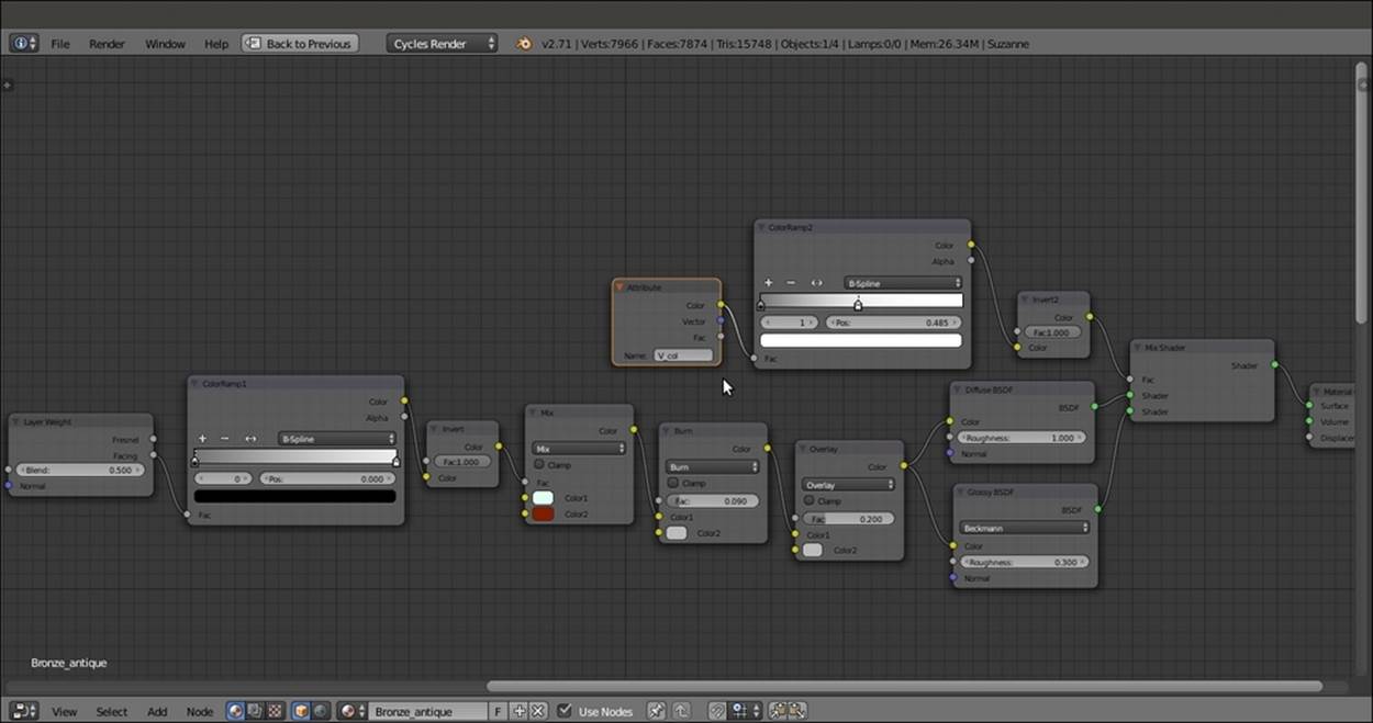
The shader modulated by the Dirty Vertex Colors output
13. Add a Texture Coordinate node (press Shift + A and navigate to Input | Texture Coordinate), a Mapping node (press Shift + A and navigate to Vector | Mapping), four Noise Texture nodes (press Shift + A, navigate to Textures | Noise Texture, and pressShift + D to duplicate them), and a Musgrave Texture node (press Shift + A and navigate to Textures | Musgrave Texture).
14. Label the four Noise Texture nodes as Noise Texture1, Noise Texture2, Noise Texture3, and Noise Texture4.
15. Connect the Object output of the Texture Coordinate node to the Vector input of the Mapping node. Connect the Vector output of this node to the Vector input sockets of all the five texture nodes.
16. For the Noise Texture1 node, set Scale to 1.000 and Detail to 5.800. For the Noise Texture2 node, set Scale to 30.000 and Detail to 0.300. For the Noise Texture3 node, set Scale to 18.500 and Detail to 0.300. Finally, for the Noise Texture4 node, set Scaleto 65.000 and Detail to 0.300.
17. For the Musgrave Texture node, set Type to Multifractal, Scale to 15.000, Detail to 2.600, Dimension to 0.800, and Lacunarity to 0.400.
18. Add a MixRGB node (press Shift + A and navigate to Color | MixRGB), set Blend Type to Difference, and label it as Difference1. Press Shift + D to duplicate it. Label the duplicate as Difference2.
19. Connect the Color output of the Noise Texture1 node to the Color1 input socket of the Difference1 node, and set the Fac output of this node to 1.000. Connect the Color output of the Musgrave Texture node to the Color2 input socket of the Difference1node.
20. Connect the Color output of the Noise Texture2 node to the Color1 input socket of the Difference2 node, and the Color output of the Noise Texture3 node to the Color2 input socket of the Difference1 node.
21. Press Shift + D to duplicate the Difference1 node, and set the Blend Type to Divide. Connect the Color output of the Difference1 node to the Color1 input socket of the Divide node, and the Color output of the Difference2 node to the Color2 input socket.
22. Add a Math node (press Shift + A and navigate to Converter | Math). Connect the output of the Divide node to the first Value input socket, and the Color output of the Noise Texture4 node to the second Value socket.
23. Press Shift + D to duplicate the Math node, and set the Operation to Multiply. Connect the Value output of the Add-Math node to the first input socket of the Multiply-Math node. Set second Value to -0.050.
24. Add a ColorRamp node (press Shift + A and navigate to Converter | ColorRamp), paste it between the Noise Texture1 node and the Difference1 node, and label it as ColorRamp3. Set Interpolation to Ease. Move the black color stop to the 0.318 position and the white color stop to the 0.686 position.
25. Connect the output of the Multiply-Math node to the Displacement input socket of the Material Output node, as shown in the following screenshot:
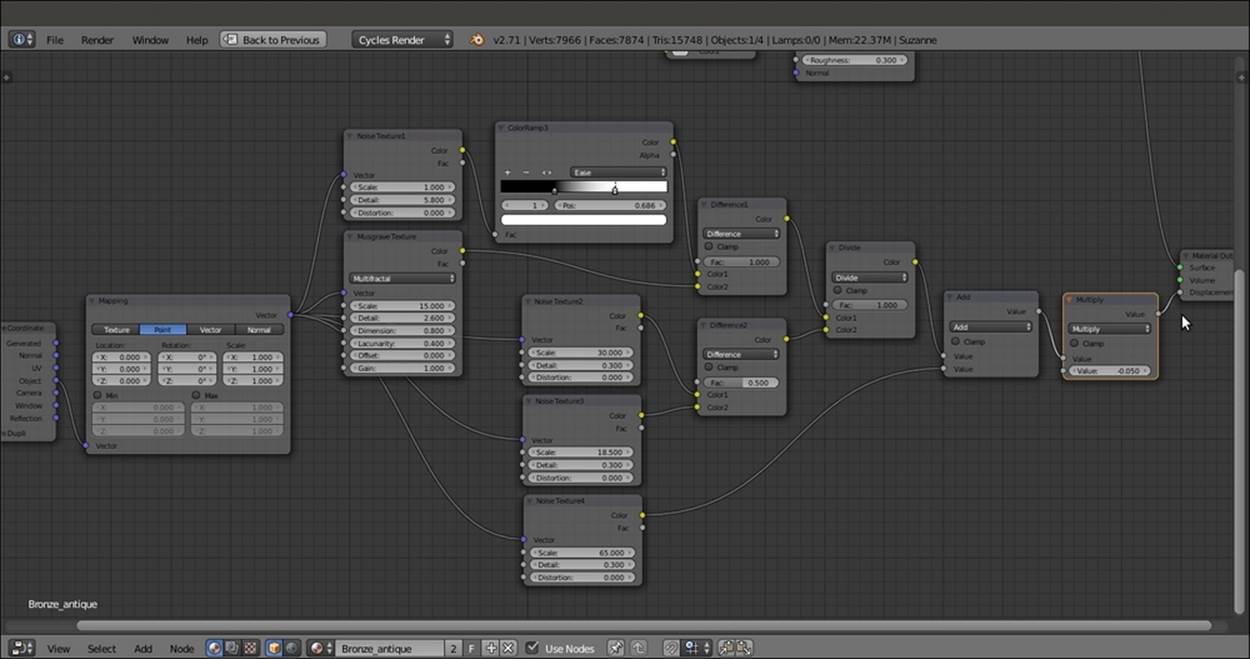
The bump pattern's nodes
26. Add two new ColorRamp nodes (press Shift + A and navigate to Converter | ColorRamp). Label them as ColorRamp4 and ColorRamp5.
27. Connect the Fac output of the Noise Texture3 node to the ColorRamp4 node. Set the color black stop to the 0.479 position and the white stop to the 0.493 position.
28. Connect the Color output of the ColorRamp4 node to the ColorRamp5 node's input socket, and the Color output of this node to the Color2 input sockets of the Burn and Overlay nodes.
29. Click on the + icon on the ColorRamp5 node to add a new color stop in the middle of the color slider. Set the black stop color (index 0) for R to 0.216, G to 0.027, and B to 0.007; the middle stop color (index 1) for R to 0.539, G to 0.261, and B to 0.000; and the white color stop color (index 2) for R to 0.515, G to 0.433, and B to 0.088, as shown in the following screenshot:
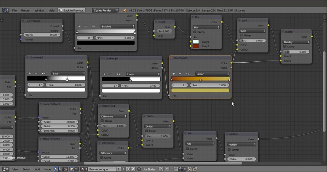
Adding color details to the ground of the bump textures
How it works...
We use the Vertex Color layer set in the Getting ready section as a stencil map to distribute both the colored Diffuse BSDF and the Glossy BSDF shaders, driven by the Facing option of the Layer Weight input node.
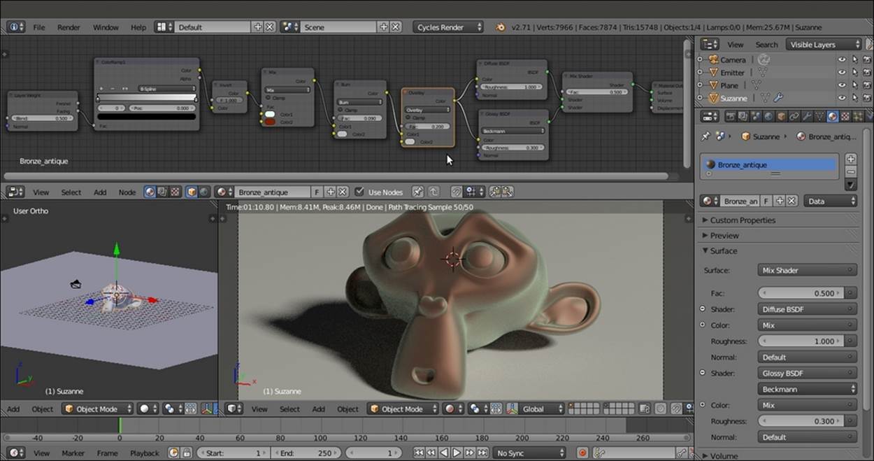
Most of the bump effect is created by the Noise Texture and Musgrave Texture nodes, which are mixed and clamped in several ways by the ColorRamp nodes. Here is a screenshot of the entire material network:
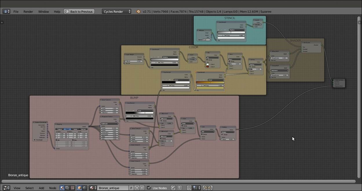
The overall view of the antique bronze material network
As usual, the last Math node, which is set to Multiply, establishes the strength of the bump.
Creating a multipurpose metal node group
All the metal materials you can see in the following screenshot (pewter, gold, silver, chromium, and aluminum) were obtained from a single shader node group linked and applied to each Suzanne with different interface settings.
To take a look at the scene, open the 9931OS_04_metals.blend file. In this recipe, we will build the generic Metal node group shader. You can find it in the 9931OS_04_metal_group.blend file, as shown in the following screenshot:
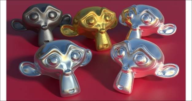
Some examples of different metal materials created by the same node group
Getting ready...
Start Blender and load the 9931OS_Suzanne_start.blend file.
How to do it...
Now we are going to create the node group by performing the following steps:
1. Click on New in the Material window under the Properties panel or in the Node Editor toolbar.
2. In the Material window, switch the Diffuse BSDF shader with a Mix Shader node, and in the first Shader slot, select a Glossy BSDF shader. In the second Shader slot, select an Anisotropic BSDF node.
3. Press Shift + D to duplicate the Mix Shader node, and paste it just after the first Mix Shader node. Add a Diffuse BSDF shader (press Shift + A and navigate to Shader | Diffuse BSDF) and connect it to the second Shader input of the second Mix Shadernode, as shown in the following screenshot:
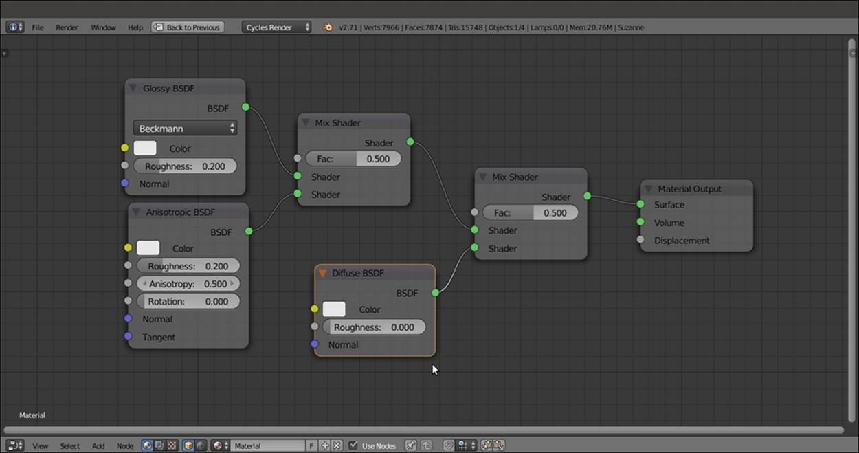
The basic metal shader network
4. Add a Fresnel node (press Shift + A and navigate to Input | Fresnel) and connect it to the Fac input of the second Mix Shader node.
5. Add a Bright Contrast node (press Shift + A and navigate to Color | Bright Contrast). Connect its Color output to the Color input sockets of the Glossy BSDF and Anisotropic BSDF shader nodes.
6. Add a Bump node (press Shift + A and navigate to Vector | Bump). Connect its Normal output to the Normal input sockets of the Fresnel, Diffuse BSDF, Glossy BSDF, and Anisotropic BSDF shader nodes.
7. Select all the nodes except the Material Output node, and press Ctrl + G to create a group, as shown in the following screenshot:
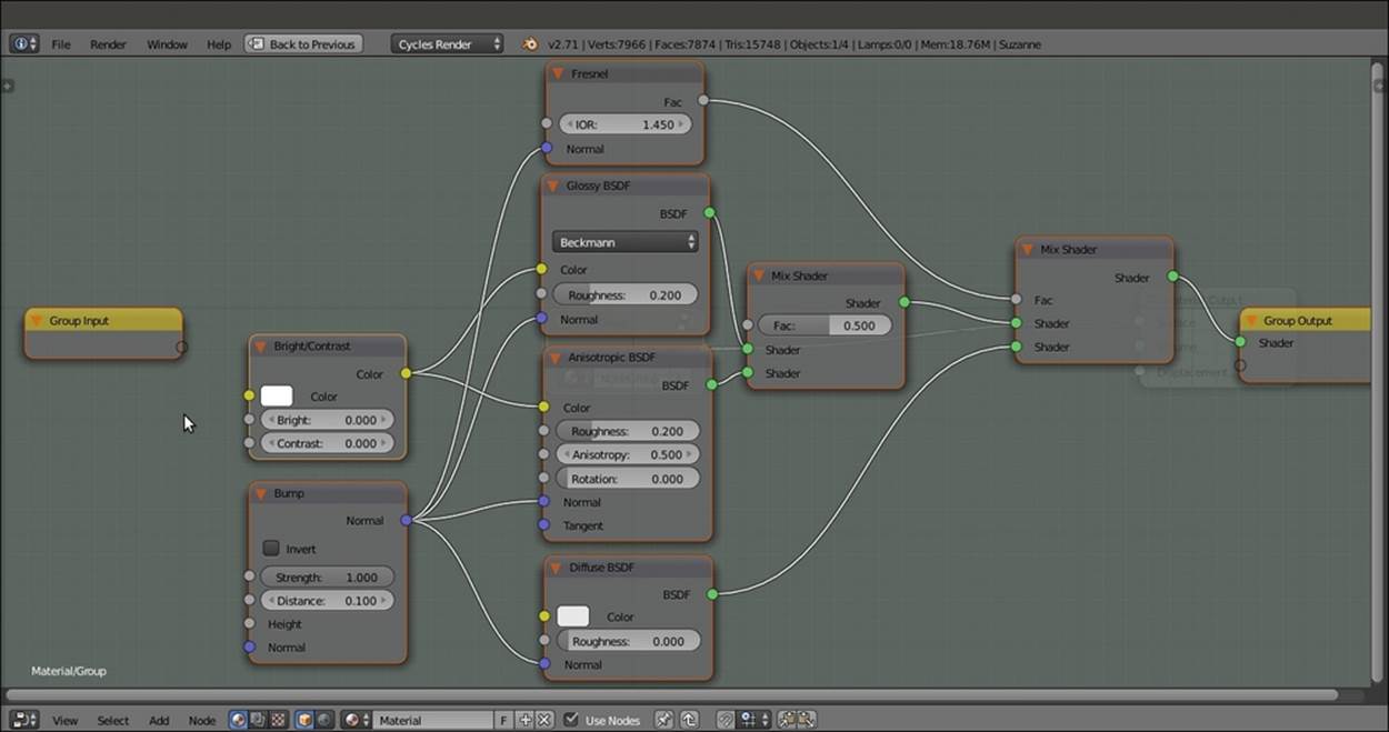
The nodes inside the node group
Now we must expose all the values necessary to tweak the node group for the different types of metal:
1. Click and drag the IOR input socket of the Fresnel node into the empty socket of the Group Input node.
2. Repeat step 1 with the Color input socket of the Diffuse BSDF shader node. Then drag the Color socket of the Bright/Contrast node and connect it to the same Color socket on the Group Input node, as shown in this screenshot:
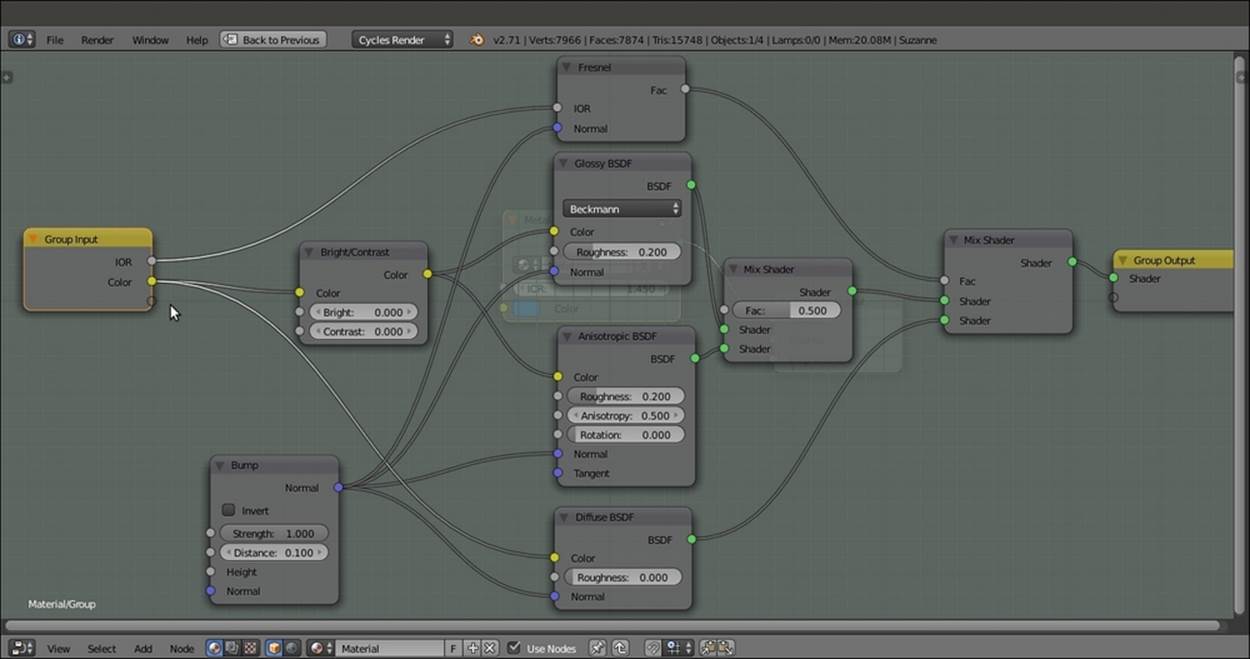
Creating the exposed sockets
3. Add a Math node (press Shift + A and navigate to Converter | Math). Set Operation to Subtract and first Value to 1.000. Drag its second Value input socket to the Group Input node, label the new socket as Coated, and then connect the Value output to theBright input socket of the Bright/Contrast node. In the Interface subpanel under the Properties panel, set the Max value for the Coated socket to 1.200, as shown in the following screenshot:
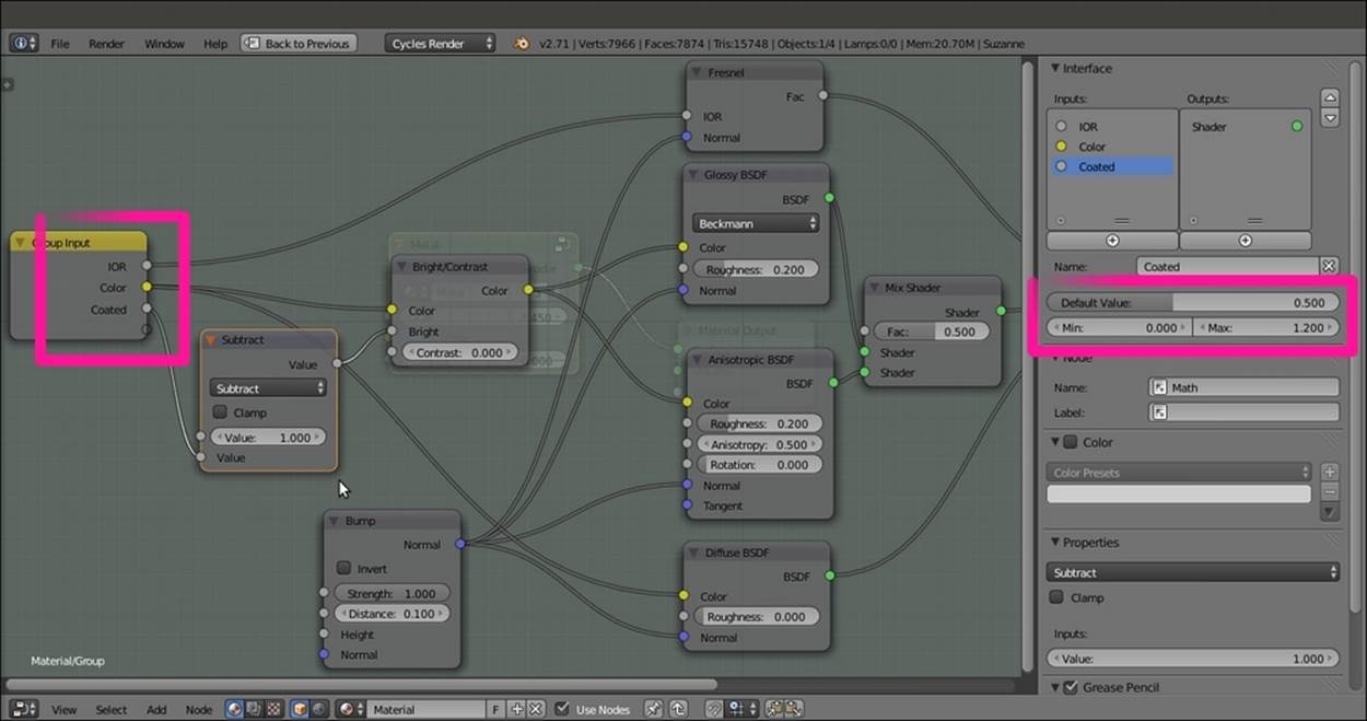
The setting of the Min and Max values through to the Interface subpanel
4. Drag the Roughness input socket of the Glossy BSDF shader. Then drag the Roughness socket of the Anisotropic BSDF shader and connect it to the same socket on the Group Input node.
5. Click and drag the Fac socket of the first Mix Shader node into a new, empty socket. Rename it Aniso_Amount. Click and drag the Anisotropy socket of the Anisotropic BSDF shader node into a new, empty socket. Repeat this step for the Rotation input socket.
6. Now click and drag the Height socket of the Bump node into a new, empty socket. Rename it Bump. Repeat this step for the Distance and the Strength sockets, and rename the sockets Bump_Distance and Bump_Strength, respectively.
7. Also repeat for the Normal socket of the Bump node.
8. Finally, click and drag the Tangent input socket of the Anisotropic BSDF shader.
9. Use the arrows in the top-right corner of the Interface subpanel to order the sockets in the Group Input node (the same order should be used for the Group Output node), as shown in the following screenshot:
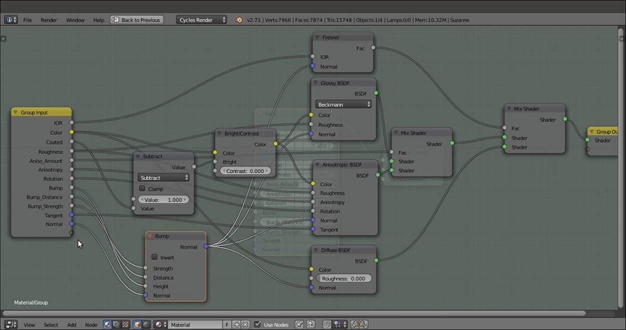
The final layout of the completed node group in Edit Mode
10. Exit Edit Mode by pressing Tab. Rename the group Metal. Although this is not "strictly necessary here, you can also click on the F icon on the interface to activate the fake user for the node group.
11. Save the file as Metal_group.blend.
How it works...
The effect of this node group is mainly based on the IOR value (the refractive index of a material is a number that describes how light propagates through that material or gets reflected on its surface). This value can be quite different for each kind of metal. In the node, the exposed IOR value drives the amount of blending of the Diffuse component with the Mirror component made by the Glossy BSDF and Anisotropic BSDF shader nodes combined, but that can also be mutually blended accordingly to the Aniso_Amountvalue.
The Anisotropy and Rotation values of the Anisotropic BSDF shader are exposed as well. and the same for the Tangent input if a particular mapping option must be used (for example, a layer of UV coordinates).
Textures must be connected to the Bump input socket on the Bump node. The Bump_Strength socket establishes the amount of bump influence. The Bump_Distance socket is a multiplier for the strength of influence. The Bump node output is piped to all theNormal input of the Fresnel, Diffuse BSDF, Glossy BSDF, and Anisotropic BSDF nodes to keep a consistent effect among all the components. Similarly, both the Glossy BSDF and Anisotropic BSDF nodes' Roughness values are driven by a single-interface input.
Finally, let's discuss the color of the metal. The color that arrives at the Diffuse BSDF shader by passing through the Bright/Contrast node gets modified by a Coated value larger than 0.000. The result is a different input for the mirror component. The Subtract-Math node simply inverts the effect of the numeric input of the Coated socket.
Besides the links provided at the end of the previous chapter, for a list of IORs, you can take a look at these links:
· http://refractiveindex.info/
· http://www.robinwood.com/Catalog/Technical/Gen3DTuts/Gen3DPages/RefractionIndexList.html
· http://forums.cgsociety.org/archive/index.php/t-513458.html
Note
Note that for some materials (especially metals), different lists report different IOR values.
Creating a rusty metal material with procedurals
In this recipe, we will create a rusty shader that will be mixed with the metal shader by a stencil factor, as shown in the following screenshot:
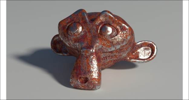
The rusty metal material as it appears in the final rendering
Getting ready...
Start Blender and load the 9931OS_Suzanne_vcol.blend file. Then perform the following steps:
1. Go to the World window. Click on the dotted little box to the right of the Color slot under the Surface subpanel. In the pop-up menu, select the Environment Texture item.
2. Click on the Open button and browse to the textures folder to load the Barce_Rooftop_C_3K.hdr image.
3. Set the Strength value to 0.200. Then go back to the Material window.
How to do it...
Now we are going to create the shader by performing the following steps:
1. Click on the File item in the upper main header. Select the Link item. If necessary, browse to the folder where you stored all the blend files. Select the 9931OS_04_metal_group.blend file. From there, click on the NodeTree entry and then select the Metal item. Click on the Link/Append from Library button to link the node group.
2. Click on New in the Material window under the Properties panel or in the Node Editor toolbar. Rename the material Rusty_metal.
3. In the Material window, switch the Diffuse BSDF shader with a Mix Shader node, and in the first Shader slot, select a Diffuse BSDF shader. In the second Shader slot, under Group in the pop-up menu, load the linked Metal node group, as shown in the following screenshot:
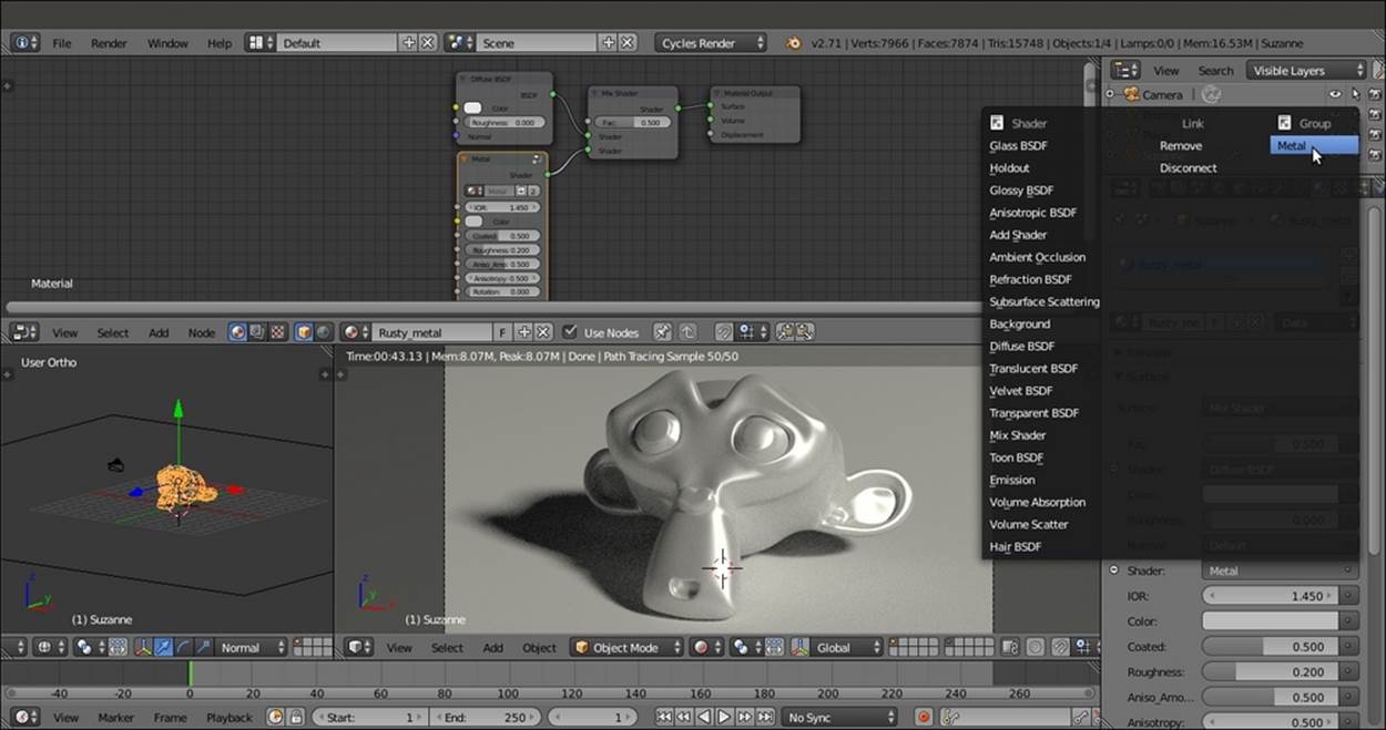
The Properties pop-up menu used to select different nodes
4. Add Frame (press Shift + A and navigate to Layout | Frame). Select the Diffuse BSDF shader, the Metal node group, the Mix Shader node, and then the Frame. Press Ctrl + P to parent them. In the Properties panel of the Node Editor window (press the Nkey to make it appear), label the Frame as SHADERS.
5. In the Metal group, set the IOR value to 1.370. Change the Color values for R to 0.229, G to 0.307, and B to 0.299. Set the Roughness value to 0.200, Aniso_Amount to 0.200, and Anisotropy to 0.600.
6. Add a Texture Coordinate node (press Shift + A and navigate to Input | Texture Coordinate) and two Mapping nodes (press Shift + A and navigate to Vector | Mapping). Connect the Object output of the Texture Coordinate node to the Vector input of both the Mapping nodes. Label them as Mapping1 and Mapping2.
7. Now add a Musgrave Texture node (press Shift + A and navigate to Texture | Musgrave Texture) and label it as Musgrave Texture1. Add a Noise Texture node (press Shift + A and navigate to Texture | Noise Texture), label it as Noise Texture1, and add aColorRamp node (press Shift + A and navigate to Converter | ColorRamp). Label this node as ColorRamp1.
8. Set the Musgrave Texture node's Scale value to 6.000 and Detail to 1.300. Press Shift + D to duplicate it, and label the duplicate as Musgrave Texture2. Set the Noise Texture node's Scale value to 7.800, Detail to 8.000, and Distortion to 2.000.
9. Connect the Vector output of the Mapping1 node to the Vector input sockets of the Musgrave Texture1 and Noise Texture1 nodes. Then connect the Vector output of the Mapping2 node to the Vector input sockets of the Musgrave Texture2 node. In theMapping2 node, set the Location value to 0.100 and Scale to 0.600 for the three axes. Then change the Rotation value of X to 7 and Y to -5.
10. Connect the Fac output of the Noise Texture node to the Fac input of the ColorRamp1 node. Set its Interpolation to Ease. Move the black color stop to the 0.321 position and the white color stop to the 0.600 position.
11. Add a MixRGB node (press Shift + A and navigate to Color | MixRGB). Set the Fac value to 1.000 and Blend Type to Add. Then connect the color output of the Musgrave Texture1 node to the Color1 input socket and the Color output of the Musgrave Texture2 node to the Color2 input socket of the Add-MixRGB node.
12. Press Shift + D to duplicate the Add-MixRGB node. Set Blend Type to Divide and the Fac value to 0.309. Connect the Fac output of the Noise Texture1 node to the Color1 input socket and the output of the Add-MixRGB node to the Color2 input socket of the Divide-MixRGB node.
13. Connect the output of the Divide-MixRGB node to the Fac input socket of the ColorRamp1 node. Press Shift + D to duplicate the Divide-MixRGB node, and change the Blend Type to Multiply. Set the Fac value to 1.000 and connect the output of theColorRamp1 node to the Color1 input socket.
14. Add an Attribute node (press Shift + A and navigate to Input | Attribute) and connect its Color output to the Color2 input socket of the Multiply-MixRGB node. In its Name slot, write the name of the Vertex Color layer, (Col_vp).
15. Add Frame (press Shift + A and navigate to Layout | Frame). Select the Musgrave Texture node, the Noise Texture node, the ColorRamp1 node, the three MixRGB nodes, the Attribute node, and then the Frame. Press Ctrl + P to parent them. Label the frame as STENCIL.
16. Connect the output of the Multiply-MixRGB node under the STENCIL frame to the Fac input socket of the Mix Shader node under the SHADERS frame, as shown in the following screenshot:
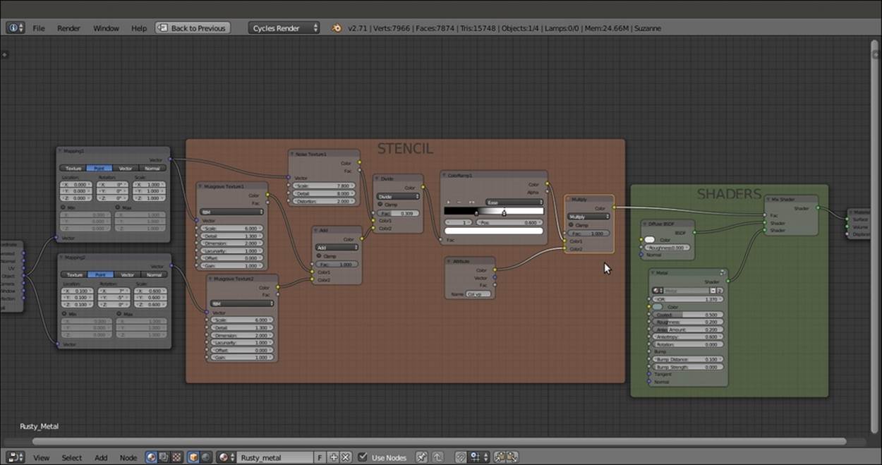
The first two frames of the material, SHADERS and STENCIL
17. Add two Voronoi Texture nodes (press Shift + A, navigate to Texture | Voronoi Texture, and label them as Voronoi Texture1 and Voronoi Texture2) and a Wave Texture node (press Shift + A and navigate to Texture | Wave Texture). In the Voronoi Texture1node, set the Coloring to Cells and the Scale value to 20.000. In the Voronoi Texture2 node, set the Scale value to 19.000. Set the Wave Texture node's Scale value to 1.000.
18. Connect the Vector output of the Mapping1 node to the Vector input sockets of these three new texture nodes.
19. Add a MixRGB node (press Shift + A and navigate to Color | MixRGB), set the Blend Type to Difference, and label it as Difference1. Set the Fac value to 1.000. Then connect the Voronoi Texture1 node's Color output to the Color1 input socket and the second Voronoi Texture2 node's Color output to the Color2 input socket.
20. Press Shift + D to duplicate the Difference1 node, and label the duplicate as Difference2. Connect the Color output of the Difference1 node to the Color1 input socket of the Difference2 node. Then connect the Color output of the Wave Texture node to theColor2 input socket.
21. Add two ColorRamp nodes (press Shift + A and navigate to Converter | ColorRamp), label them as ColorRamp2 and ColorRamp3, and connect the output of the Difference2 node to their Fac input socket. Set the ColorRamp2 node's Interpolation to Ease and move the black color stop to the 0.486 position. Set the ColorRamp3 node's Interpolation to B-Spline and move the black color stop to the 0.304 position.
22. Press Shift + D to duplicate the Difference2 node, and label the duplicate as Difference3. Place it after the ColorRamp2 node and ColorRamp3 nodes. Connect the ColorRamp2 node's Color output to the Color1 input socket and the ColorRamp3 node'sColor output to the Color2 input socket of the Difference3 node.
23. Add Frame (press Shift + A and navigate to Layout | Frame). Select these lastly added nodes and then the Frame. Press Ctrl + P to parent them. Rename the frame RUST_BUMP.
24. Select the SHADERS frame and add a Bump node (press Shift + A and navigate to Vector | Bump). Connect the Difference3 node's output to the Height input socket of the Bump node. Connect the Normal output of this node to the Normal input socket of the Diffuse BSDF node inside the SHADERS frame, as shown in the following screenshot:
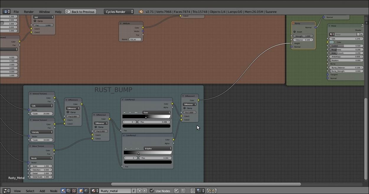
The frame for the bump of the rust
25. Select the STENCIL frame and add a MixRGB node (press Shift + A and navigate to Color | MixRGB) and a Bright/Contrast node (press Shift + A and navigate to Color | Bright Contrast). Paste the MixRGB node right after the Multiply-MixRGB node. Set Blend Type to Difference and then connect the output of the Difference3 node inside the RUST_BUMP frame to the Color2 input socket. Paste the Bright/Contrast node right after this last Difference node. Set the Bright value to 0.500 and theContrast value to 1.000, as shown in the following screenshot:
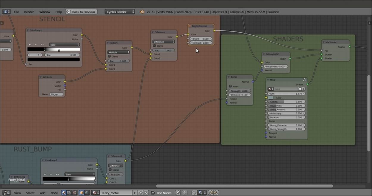
The RUST_BUMP output added to the stencil to separate the metal surface from the rusty surface
26. Add an RGB Curves node (press Shift + A and navigate to Color | RGB Curves), two ColorRamp nodes (press Shift + A, navigate to Converter | ColorRamp, and label them as ColorRamp4 and ColorRamp5), a Noise Texture node (press Shift + A, navigate toTexture | Noise Texture, and label it as Noise Texture2), and a MixRGB node (press Shift + A and navigate to Color | MixRGB).
27. In the RGB Curves node's interface, click on the diagonal line to add a control point. In the X and Y slots at the bottom, set the values to 0.50000 and 0.26000, respectively. Click again to add a new control point, and set X to 0.51000 and Y to 0.75000.
28. Connect the Color output of the RGB Curves node to the Fac input of the ColorRamp5 node.
29. Go to the ColorRamp4 node. Select the black color stop and change the color values of R to 0.991, G to 0.591, and B to 0.084. Select the white color stop and change the color values of R to 0.105, G to 0.013, and B to 0.010.
30. Click four times on the + icon on the ColorRamp4 node interface to add four new color stops. Select 4 as the index number and move it to the 0.889 position. Change the color values of R to 0.930, G to 0.456, and B to 0.105. For index 3, set Pos to 0.754, R to0.624, G to 0.250, and B to 0.053. For index 2, set Pos to 0.521, R to 0.418, G to 0.159, and B to 0.068. Finally, for index 1, set Pos to 0.286, R to 0.246, G to 0.098, and B to 0.034.
31. With the mouse arrow inside the colorband on the ColorRamp4 node, press Ctrl + C to copy it. Move the mouse arrow to the colorband of the ColorRamp5 node. Press Ctrl + V to paste the colors and the stops. Set the ColorRamp5 node's Interpolation toConstant.
32. Connect the Color output of both the ColorRamp4 and ColorRamp5 nodes to the Color1 and Color2 input sockets of the MixRGB node, respectively. Set the MixRGB node's Blend Type to Dodge and the Fac value to 1.000.
33. Press Shift + D to duplicate the Dodge-MixRGB node, set the Blend Type to Multiply, and label it as Multiply2. Lower the Fac value to 0.500. Connect the Dodge-MixRGB node's output to the Color1 input of the Multiply2 node and the Color output of theNoise Texture2 node to the Color2 input.
34. Set the Noise Texture2 node's Scale value to 16.000, Detail to 2.500, and Distortion to 1.000. Connect the Object output of the Mapping1 node to the Vector input of the Noise Texture2 node.
35. Add a Hue Saturation Value node (press Shift + A and navigate to Color | Hue Saturation Value). Place it right after the Multiply2 node. Connect the Multiply2 output to the Color input socket of the Hue Saturation Value node. Then set the Hue value to0.465 and the Saturation value to 1.050.
36. Press Shift + D to duplicate the Multiply2 node, and place the duplicate close to the Noise Texture2 node. Set the Blend Type to Overlay and the Fac value to 0.250. Connect the Fac output of the Noise Texture2 node to the Color1 input socket of theOverlay-MixRGB node, and change Color2 to pure white. Connect the Overlay-MixRGB node's output to the Value input socket of the Hue Saturation Value node.
37. Add Frame (press Shift + A and navigate to Layout | Frame). Select these recently added nodes and then the Frame. Press Ctrl + P to parent them. Rename the frame RUST_COLOR.
38. Connect the output of the Hue Saturation Value node inside the RUST_COLOR frame to the Color input socket of the Diffuse BSDF shader node inside the SHADERS frame. Then connect the Color output of the Divide node inside the STENCIL frame to the Color input of the RGB Curves node inside the RUST_COLOR frame, as shown in the following screenshot:
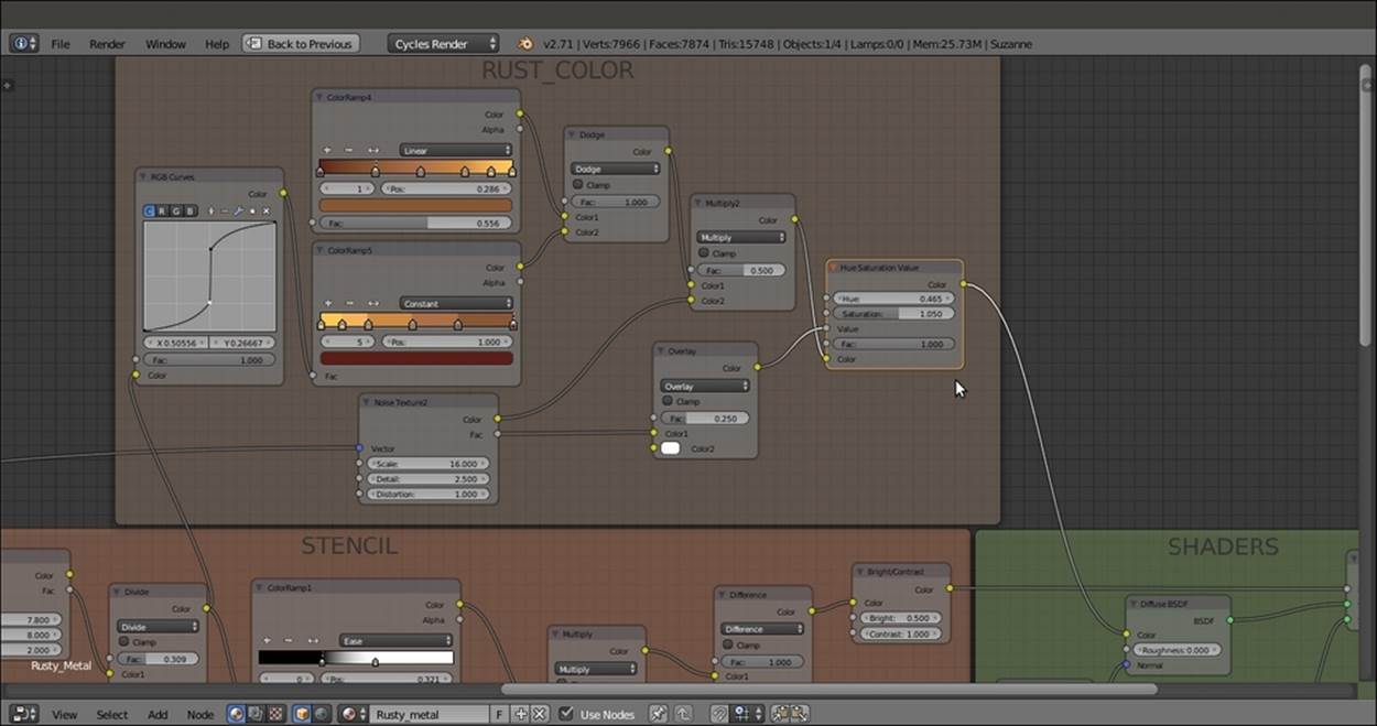
The color of the rusty surface added to the network
39. Save the file as Metal_rusty.blend.
How it works...
From step 2 to step 4, we built the basic shader arrangement. From step 6 to step 15, we made the STENCIL frame to separate the rust material from the polished metal.
From step 17 to step 23, we built the bump effect for the rust, and from step 26 to step 37, we added the rust color.
There's more...
We used the Dirty Vertex Colors layer named Col_vp again, this time to give a denser pattern to certain areas of Suzanne compared to other areas. Remember that a Vertex Colors layer can be modified and improved by manual vertex painting on the mesh inVertex Paint mode. We can also use a gray-scale image map, painted in GIMP or in Blender itself and then UV-mapped on the mesh to obtain more precise and localized effects.
Creating a wood material with procedurals
In this recipe, we will create a generic wood material—a shader that can be easily adapted to different situations—as shown in the following screenshot:
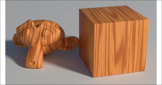
The procedural wood material as it appears in the final rendering
Getting ready...
Start Blender and load the 9931OS_Suzanne_start.blend file. Then perform these steps:
1. Go to the World window and click on the button with a dot icon to the right of the Color slot under the Surface subpanel. In the pop-up menu, select the Environment Texture item.
2. Click on the Open button and browse to the textures folder to load the Barce_Rooftop_C_3K.hdr image.
3. Set the Strength value to 0.300. Then go back to the Material window.
4. Go to the Camera view and add a Cube primitive to the scene. Place it leaning on the Plane, to the right of Suzanne. Move it up by 1 Blender unit.
5. With the mouse arrow in the Camera view, press Shift + F to enter Walk Mode. Adjust the Camera position to center the two objects in the frame.
6. Select the Cube, go to Edit Mode, and scale it to at least twice its current size. Exit Edit Mode, and using the 3D manipulator widget (which can be enabled in the 3D view toolbar), move the Cube upwards to stay nicely on the Plane. Press N, and in theProperties panel, select the Lock Camera to View item. Then adjust the Camera position framing the two objects.
7. Assign a Bevel modifier to the Cube, set Width to 0.0450, and set the Segments value to 4.
8. Press T to call the Tool Shelf panel. Set the Cube shading to Smooth.
9. Select Suzanne and rotate it a bit towards the left on the z axis.
10. Press T to close the Tool Shelf panel.
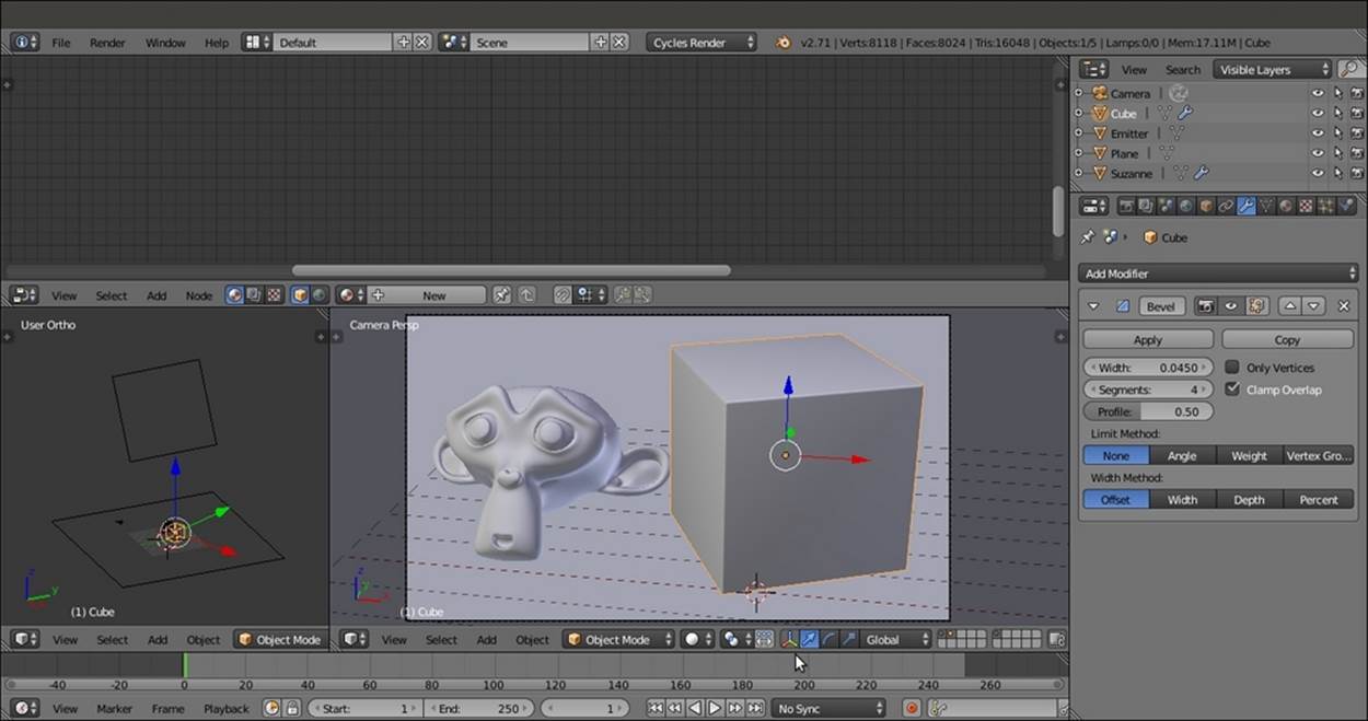
Setting up the scene
How to do it...
Now we are going to create the material by performing the following steps:
1. Click on New in the Material window under the Properties panel or in the Node Editor toolbar. Rename the material Wood.
2. Switch the Diffuse BSDF shader with a Mix Shader node, and in the first Shader slot, select a Diffuse BSDF shader. In the second Shader slot, select a Glossy BSDF node. Set the Glossy BSDF node's Roughness value to 0.300.
3. Add a Fresnel node (press Shift + A and navigate to Input | Fresnel) and a MixRGB node (press Shift + A and navigate to Color | MixRGB). Set the IOR value of the Fresnel node to 2.000. Connect its output to the Color1 input socket of the MixRGB node. Set the MixRGB node's Blend Type to Multiply, label it as Multiply1, and set the Fac value to 0.900. Connect the Multiply1 node's output to the Fac input socket of the Mix Shader node.
4. Add Frame (press Shift + A and navigate to Layout | Frame). Select the Diffuse BSDF, Glossy BSDF, Mix Shader, Multiply1, and Fresnel nodes. Then select the Frame and press Ctrl + P to parent them. Label the frame as SHADERS.
5. Add one Texture Coordinate node (press Shift + A and navigate to Input | Texture Coordinate) and three Mapping nodes (press Shift + A; navigate to Vector | Mapping; add the first node; duplicate the other nodes; and then label them as Mapping1,Mapping2, and Mapping3). Connect the Object output of the Texture Coordinate node to the Vector input of the three Mapping nodes.
6. Set the Scale value of the Mapping1 node to 2.000 for all the three axes. Set the Scale value only for the x axis of the Mapping2 node to 20.000. Then set the Scale value only for the x axis of the Mapping3 node to 15.000.
7. Add a Noise Texture node (press Shift + A and navigate to Texture | Noise Texture) and two Wave Texture nodes (press Shift + A and navigate to Texture | Wave Texture). Label them as Noise Texture1, Wave Texture1, and Wave Texture2.
8. Set the Scale of the Noise Texture1 node to 6.000 and Detail to 0.000. Connect the Mapping1 node's output to the Noise Texture node's Vector input socket.
9. Connect the Mapping2 node's output to the Vector input of the Wave Texture1 node. Set the Wave Texture1 node's Scale value to 0.200 and Distortion to 20.000.
10. Connect the Mapping3 node output to the Wave Texture2 node's Vector input socket. Set Wave Type to Rings, the Scale value to 0.070, and the Distortion value to 44.000.
11. Add a MixRGB node (press Shift + A and navigate to Color | MixRGB). Set the Blend Type to Multiply (label it as Multiply1) and the Fac value to 1.000. Connect the Noise Texture node's Color output to the Color1 input socket and the Wave Texture1node's Color output to the Color2 input socket.
12. Connect the Multiply1 node's output to the Color input of the Diffuse BSDF shader. Press Shift + D to duplicate it, change the Blend Type to Add, and paste it between the Multiply1 node and the Diffuse BSDF shader node. Connect the Wave Texture2node's Color output to the Color2 input socket of this Add-MixRGB node (labelled as Add1).
13. Add a ColorRamp node (press Shift + A and navigate to Converter | ColorRamp), label it as ColorRamp1, and paste it right after the Noise Texture1 node. Set Interpolation to B-Spline and move the black color stop to the 0.345 position.
14. Press Shift + D to duplicate the ColorRamp1 node, paste it right after the Wave Texture1 node, and label it as ColorRamp2. Move the black color stop to the 0.505 position and the white color stop to the 0.975 position.
15. Press Shift + D to duplicate the ColorRamp2, label it as ColorRamp3, and paste it right after the Wave Texture2 node. Move the black color stop to the 0.495 position and the white color stop to the left end of the slider, and set Pos as 0.000, as shown in the following screenshot:
The textures required to draw the wood effect summed and connected to the shader part of the material
16. Now add a MixRGB node (press Shift + A and navigate to Color | MixRGB) and connect the Add1 node's Color output to its Fac input socket. Set the Color1 values of R to 1.000, G to 0.500, and B to 0.150. Set the Color2 values of R to 0.694, G to 0.205, andB to 0.027.
17. Press Shift + D to duplicate the MixRGB node. Paste the duplicate right after the original node. Connect the MixRGB node's output to the Color2 input socket, change Blend Type to Multiply, and label it as Multiply3.
18. Add a Frame (press Shift + A and navigate to Layout | Frame). Press Shift and select the three texture nodes, the three ColorRamp nodes, the four MixRGB nodes, and then the Frame. Press Ctrl + P to parent them. Label the frame as COLOR, as shown in the following screenshot:
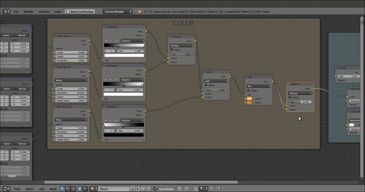
Adding more color to the veining
19. Add a new Noise Texture node (press Shift + A, navigate to Texture | Noise Texture, and label it as Noise Texture2), a Math node (press Shift + A and navigate to Converter | Math), and a Bump node (press Shift + A and navigate to Vector | Bump).
20. Connect the Mapping3 node's output to the Vector input socket of the Noise Texture2 node. Then connect the Color output of this node to the second Value input of the Math node. Set its Operation to Add, label it as Add2, and connect its output to theHeight input socket of the Bump node.
21. Set the Bump node's Strength value to 0.200. Connect the Normal output of the Bump node to the Normal input of the Fresnel, Diffuse BSDF, and Glossy BSDF nodes inside the SHADERS frame. Set the Noise Texture2 node's Scale value to 43.000 andDetail to 16.000.
22. Go to the Add1 node inside the COLOR frame, click on the output node, and drag it so that it is connected to the first Value input socket of the Add2-Math node.
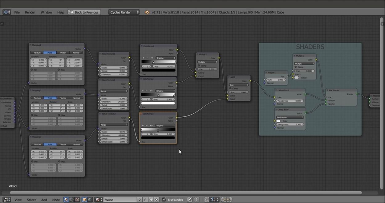
23. Add a Frame (press Shift + A and navigate to Layout | Frame). Select the three nodes and then the Frame. Press Ctrl + P to parent them. Label the frame as BUMP, as shown in the following screenshot:
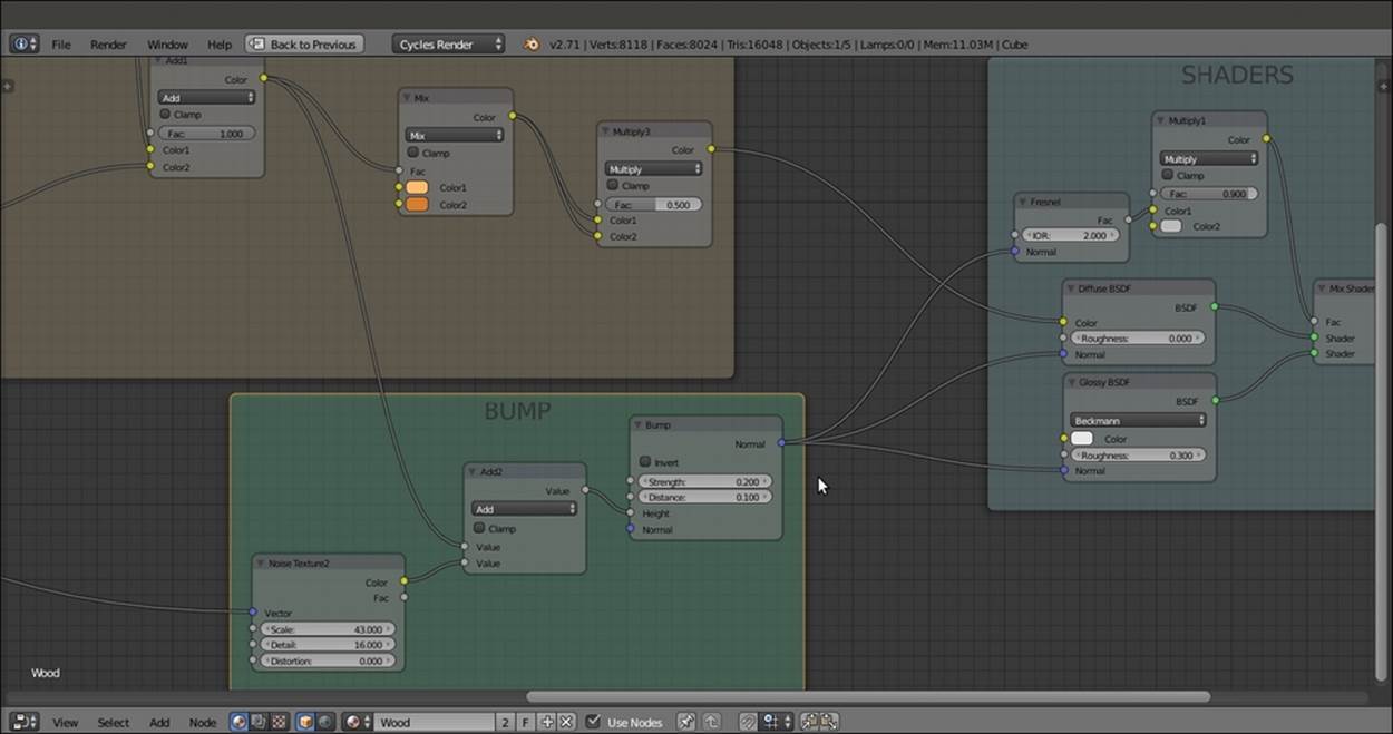
The bump pattern, based in part on the output of the veining
24. Save the file as Wood.blend.
How it works...
From steps 1 to 4, we built the basic shader using the usual Diffuse BSDF and Glossy BSDF nodes, mixed by a Fresnel value and multiplied by the values of a medium gray color.
From steps 5 to 18, we built the color of the wood's veins, adding three procedurals to be used as splitting factors for the two wood colors set in the penultimate MixRGB node. Using the last Multiply3 node, we made the color more saturated (actually, we multiplied the values by themselves).
From steps 19 to 23, we built the bump using a noise grain summed to the veins' values by the Add2-Math node. We set a low value for the bump's Strength value, but you can use higher values (together with higher roughness values) to obtain less polished surfaces, which can give you different kinds of wood in the output.
All materials on the site are licensed Creative Commons Attribution-Sharealike 3.0 Unported CC BY-SA 3.0 & GNU Free Documentation License (GFDL)
If you are the copyright holder of any material contained on our site and intend to remove it, please contact our site administrator for approval.
© 2016-2026 All site design rights belong to S.Y.A.