Blender Cycles: Materials and Textures Cookbook, Third Edition (2015)
Chapter 5. Creating Complex Natural Materials in Cycles
In this chapter, we will cover the following recipes:
· Creating an ocean material using procedural textures
· Creating underwater environment materials
· Creating a snowy mountain landscape with procedurals
· Creating a realistic earth as seen from space
Introduction
In Chapter 3, Creating Natural Materials in Cycles, we saw some of the simpler natural materials that are possible to build in Cycles, keeping them out of any landscape context to make them more easily understandable.
Now it's time to deal with more elaborate natural materials. In this chapter, we will examine the way to mix different basic shaders to mimic the look of complex natural objects and their environments (very often, these two things fit together neatly).
Creating an ocean material using procedural textures
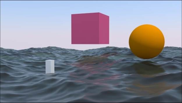
In this recipe, we will build an ocean surface material, using the Ocean modifier and procedural textures to create the foam, and establish a set of nodes to locate it on the higher parts of the waves:
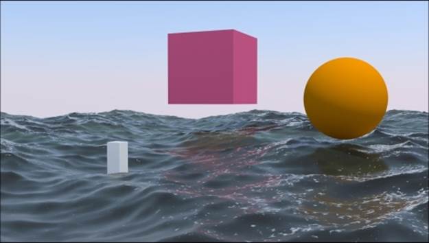
The final look of the ocean material, with three simple and brightly colored objects to be reflected by the surface
Getting ready
Before we start with creating the shaders, let's prepare the ocean scene:
1. Start Blender and switch to the Cycles rendering engine. Select the default Cube, delete it (press X), and add a Plane (with the mouse arrow in the 3D window, press Shift + A and navigate to Mesh | Plane). In Object Mode, scale the plane smaller to 0.300. Don't apply a size.
2. Go to the Object modifiers window and assign an Ocean modifier. Set these values of Geometry to Generate, Repeat X and Repeat Y to 4, Spatial Size to 20, and Resolution to 12.
3. Press the N key, and in the Transform panel, set these values for the Plane in Location for X as -6.90000, Y as -7.00000, and Z as 0.00000.
4. Make sure that you are at frame 1, and with the mouse arrow in the modifier's Time slot, press I to add a key for the animation. Go to frame 25, change the Time value from 1.00 to 2.00, and press the I key again to set a second key.
5. In the Choose Screen layout button at the top, switch from Default to Animation. In the Graph Editor window, press T. In the Set Keyframe Interpolation pop-up menu, select the Linear item under Interpolation. Then press Shift + E, and in the Set Keyframe Extrapolation pop-up menu, select the Linear Extrapolation item to make the ocean animation constant and continuous.
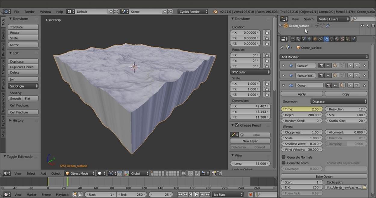
6. Go back to the Default screen and rename the Plane as Ocean_surface. Have a look at the following screenshot:
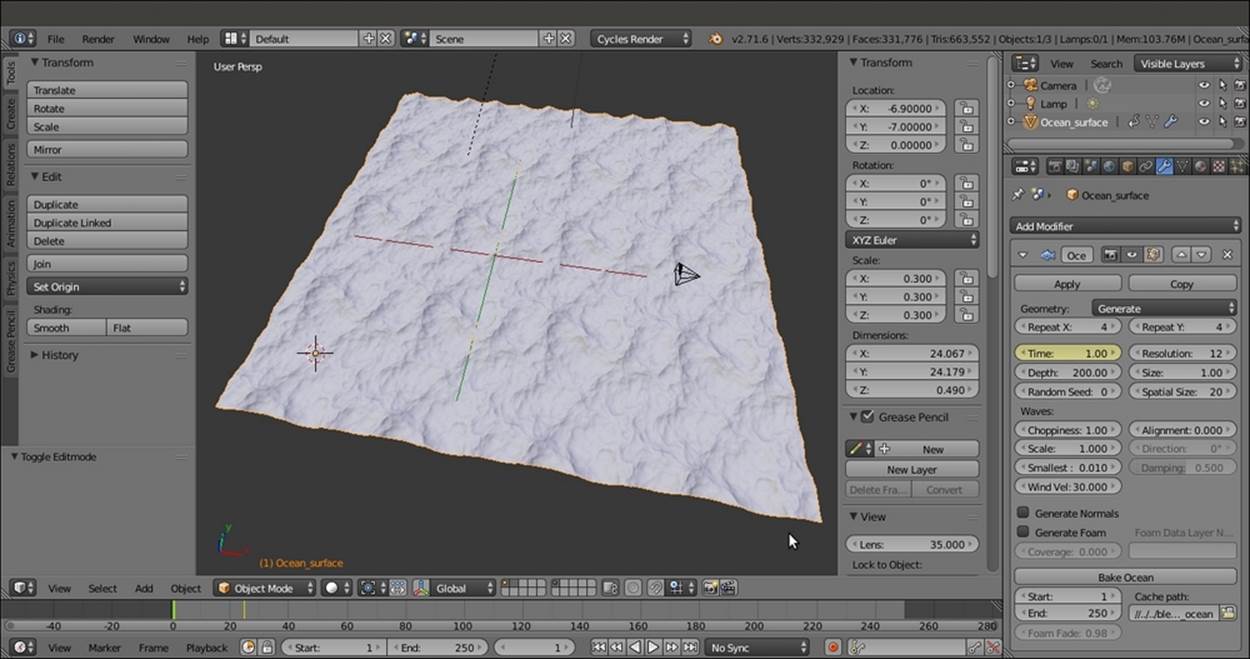
The Plane with the assigned Ocean modifier, and the settings to the right
7. Place the Camera to have a nice angle on the ocean, and then go to the Camera view (press 0 on the numeric keypad).
8. Add a Cube in the middle of the scene and, if you want, a UV Sphere in the foreground. Place these so that they float in the air. Their only purpose is to get reflected by the ocean surface during the shader setup.
9. Go to the World window and click on the Use Nodes button under the Surface subpanel. Then click on the little square with a dot on the right side of the color slot. From the pop-up menu, navigate to Texture | Sky Texture.
10. Select the Lamp, go to the Object data window, and click on the Use Nodes button under the Nodes subpanel. Set a yellowish color for the light (change the value of R to 1.000, G to 0.989, and B to 0.700). Turn it to Sun, set the Size value to 0.010, and set the Strength value to 2.500.
11. Go to the Render window, and under the Sampling subpanel, set both the Clamp Direct and Clamp Indirect values to 1.00. Set the samples to 100 for Render and 50 for Preview (you can obviously change these values according to the power of your machine).
Now, because the shader we are going to build is largely transparent, we need to simulate the water body as seen from above the surface.
12. Add a new Plane in Edit Mode and scale it 10 times bigger (20 Blender units per side; press Tab, then press S, enter digit 10, and press Enter). Exit Edit Mode and move the Plane so that it is centered on the ocean Plane location, then move it 1 unit down on the z axis. You can do it like this: go to the Top view and move the new Plane of 7 Blender units first along the x axis and then along the y axis. Then press G, press Z, enter digit -1, and press Enter.
13. In Edit Mode, press W to subdivide it by the Specials menu. Then press T to open the Tool Shelf panel on the left, and under Number of Cuts in the Operator panel at the bottom, and select 3.
14. Go to the Vertex Paint mode and paint a very simple gray-scale gradient, changing from black at the vertices close to the Camera location to a plain white color on the opposite side.
There are five rows of vertices on the Plane (ideally, all the rows are along the global x axis), so you can paint the first row with RGB value as 0.000, second with RGB value as 0.250, third with RGB value as 0.500, fourth with RGB value as 0.750, and fifth withRGB value as 1.000 to have a perfect gray-scale gradient.
15. In the Object data window, under the Vertex Colors tab, rename the Vertex Color layer as Col_emit. Have a look at the following screenshot:
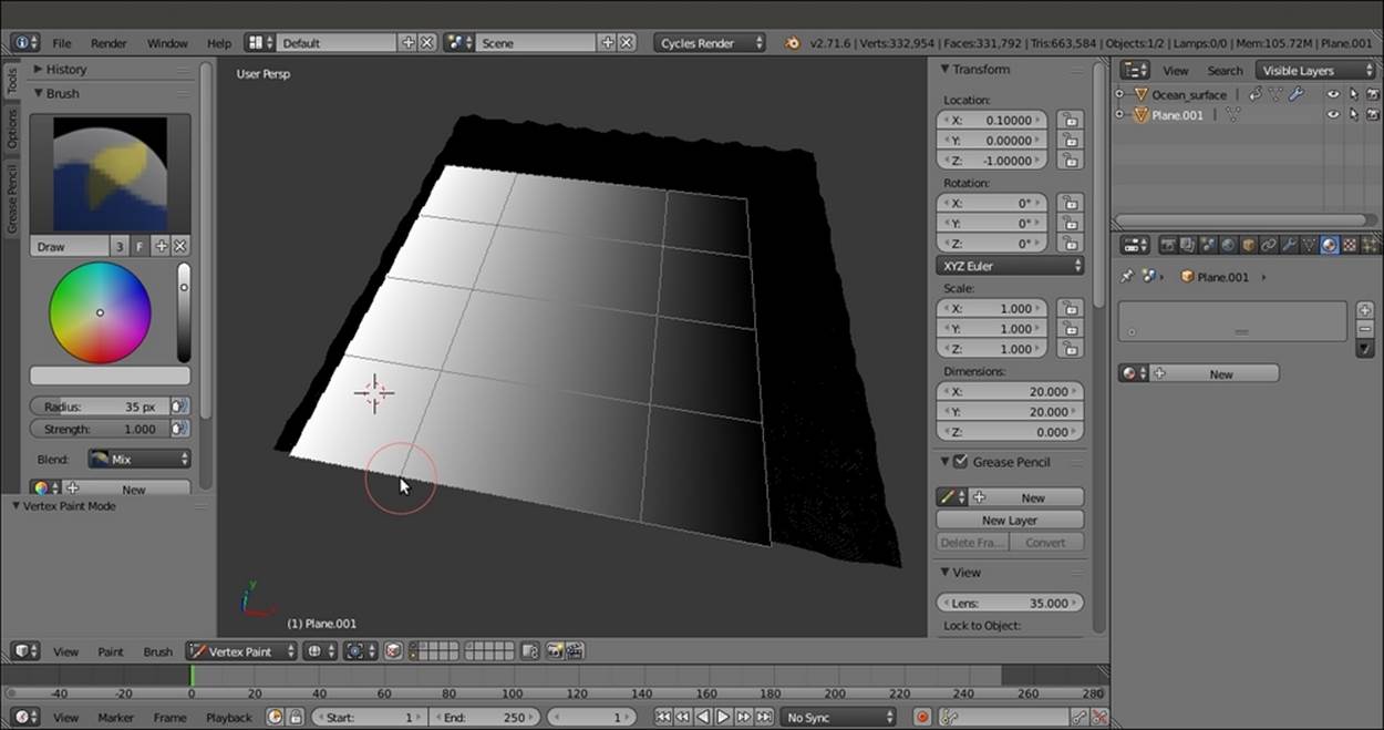
The Ocean_Bottom plane with the painted Vertex Colors layer
16. Exit Vertex Paint mode and rename this second Plane Ocean_bottom.
17. Split the 3D window into two horizontal rows. Change the upper row to a Node Editor window.
18. Assign very simple colored materials to the Cube and the UV Sphere; plain Diffuse BSDF shaders are enough.
How to do it...
We will be performing this in four parts:
· Creating the water surface and the bottom shaders
· Creating the foam shader
· Creating the stencil material for the location of foam
· Putting everything together
Let's start!
Creating the water surface and the bottom shaders
Let's now create the water surface and the bottom shaders:
1. Select the Ocean_bottom object. Click on the New button in the Material window under the Properties panel or in the Node Editor toolbar. Rename the new material as Ocean_bottom as well.
2. Switch the Diffuse BSDF shader with a Mix Shader node. In the first and the second slots, load two Emission shaders.
3. Add an Attribute node (press Shift + A and navigate to Input | Attribute) and connect the Color output to the Fac input of the Mix Shader node. In the Name slot of the Attribute node, write Col_emit, which is the name of the Vertex Color layer.
4. Change the color of the first Emission node for R to 0.178, G to 0.150, and B to 0.085. Set the Strength value to 1.000.
5. Change the color values of the second Emission node for R to 0.213, G to 0.284, and B to 0.380. Set the Strength value to 2.000.
The Ocean_bottom material is ready. Have look at the following screenshot:
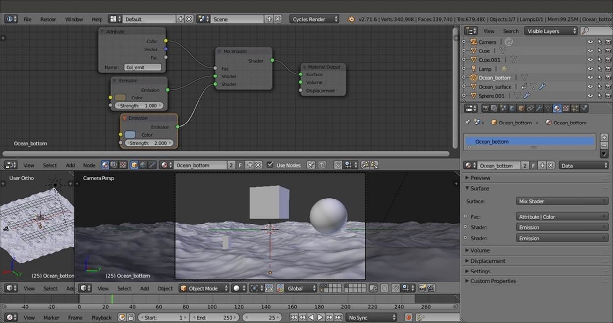
The Ocean_bottom material and the scene visible in the Solid viewport shading mode through the Camera view
6. Now select Ocean_surface and click on New in the Material window under the Properties panel or in the Node Editor toolbar. Rename this material as Ocean_surface.
7. Replace the Diffuse BSDF node with a Mix Shader node, and in the first Shader slot, assign a Transparent BSDF node. In the second slot, assign a Glass BSDF shader. In the Properties panel of the Node Editor window, label the Mix Shader node as Mix Shader01.
8. Change the Transparent BSDF nodes Color values for R to 0.055, G to 0.124, and B to 0.042 (you can also do this by connecting an RGB node to the Color input socket, as shown in the example blend file provided). Set the Glass BSDF shader node'sRoughness value to 0.900 and the IOR value to 1.333.
9. Add a Layer Weight node (press Shift + A and navigate to Input | Layer Weight), connect the Facing output to the Fac input of the Mix Shader01 node, and set the Blend value to 0.050.
10. Select the Mix Shader01 node and press Shift + D to duplicate it. Add a Glossy BSDF shader (press Shift + A and navigate to Shader | Glossy BSDF) and connect it to the second Shader input socket of the Mix Shader02 node. Connect the output of theMix Shader01 node to the first Shader input socket of the Mix Shader02 node, and the output of this node to the Surface input of the Material Output node.
11. Add a Fresnel node (press Shift + A and navigate to Input | Fresnel). Connect this to the Fac input of the Mix Shader02 node. Set the IOR value to 1.333 as shown in the following screenshot:
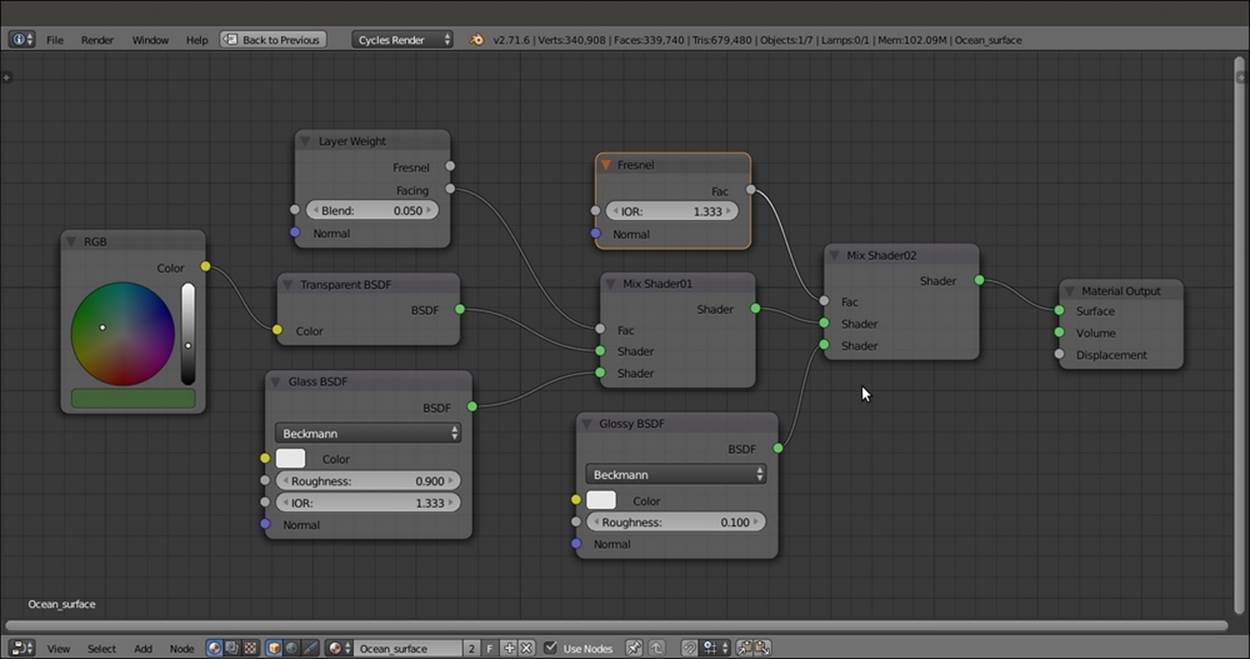
The Ocean_surface shader network
12. Now select all the nodes except the Material Output node, and press Ctrl + G to make a group. Select and delete the Group Input node to the left (press the X key), and drag the Mix Shader02 node's output to the empty socket of the Group Output node.
13. Press Tab to close the node group, and rename it as Ocean_water.
Creating the foam shader
Let's now create the shader for the foam:
1. Add a Noise Texture node (press Shift + A and navigate to Texture | Noise Texture) and a Voronoi Texture node (press Shift + A and navigate to Texture | Voronoi Texture) nodes. Select them and press Shift + D to duplicate them. Label them as Noise Texture01, Noise Texture02, Voronoi Texture01, and Voronoi Texture02.
2. Add four ColorRamp nodes (press Shift + A and navigate to Converter | ColorRamp, then press Shift + D to duplicate them). Label them as ColorRamp01, ColorRamp02, ColorRamp03, and ColorRamp04. Place the four texture nodes in a vertical column and arrange the ColorRamp nodes to their side. Connect the Color output of each texture node to the Fac input of the respective ColorRamp node.
3. Set Interpolation of the ColorRamp01 node to B-Spline, ColorRamp02 and ColorRamp03 to Ease, and ColorRamp04 to B-Spline again.
4. Go to the ColorRamp01 node. Move the black color stop to position 0.345 and the white color stop to position 0.633.
5. Go to the ColorRamp02 and ColorRamp03 nodes. Move the black color stop to position 0.159 and the white color stop to position 0.938 for both nodes. Leave the ColorRamp04 color stops as they are.
6. Set the Scale value of the Noise Texture01 node to 500.000, the Noise Texture02 node to 100.000, the Voronoi Texture01 node to 100.000, and the Voronoi Texture02 node to 90.000.
7. Add a Texture Coordinate node (press Shift + A and navigate to Input | Texture Coordinate) and a Mapping node (press Shift + A and navigate to Vector | Mapping). Connect the UV output of the Texture Coordinate node to the Vector input socket of theMapping node. Then connect the Vector output of this node to the Vector input sockets of the four texture nodes.
8. Add a MixRGB node (press Shift + A and navigate to Color | MixRGB), set the Blend Type to Subtract, and label it as Subtract01. Set the Fac value to 1.000. Connect the Color outputs of the ColorRamp01 and ColorRamp02 nodes to the Color1 andColor2 input sockets of the Subtract01 node.
9. Select the Subtract01 node, press Shift + D to duplicate it, and set the Blend Type to Multiply. Label it as Multiply and connect the Color outputs of the ColorRamp03 and ColorRamp04 nodes to its Color1 and Color2 input sockets.
10. Duplicate a MixRGB node again, set the Blend Type to Difference, and name it Difference as well. Then connect the Color outputs of the ColorRamp03 and ColorRamp04 nodes to the Color1 and Color2 input sockets of this Difference node.
11. Duplicate one of the MixRGB nodes one more time. Set the Blend Type to Lighten and label it as Lighten. Lower the Fac value to 0.500. Connect the Color output of the Multiply node to the Color1 input of the Lighten node, and the Color output of theDifference node to the Color2 input socket.
12. Add an Invert node (press Shift + A and navigate to Color | Invert) and move it on the link connecting the Difference and the Lighten nodes to be automatically pasted in between.
13. Add a new ColorRamp node, label it as ColorRamp05, and connect the Lighten node output to its Fac input. Then move the black color stop to position 0.298 and the white color stop to position 0.486.
14. Add a new MixRGB node (press Shift + A and navigate to Color | MixRGB), set the Blend Type to Subtract, and label it as Subtract02. Set the Fac value to 1.000. Connect the ColorRamp05 node's Color output to the Color1 input of Subtract02 node and the output of the Subtract01 node to the Color2 input socket.
15. Add an RGB to BW node (press Shift + A and navigate to Converter | RGB to BW), a Bump node (press Shift + A and navigate to Vector | Bump), and a Diffuse BSDF shader (press Shift + A and navigate to Shader | Diffuse BSDF).
16. Connect the Subtract02 node's output to the RGB to BW node, the output of this node to the Height input socket of the Bump node, and the Normal output of the Bump node to the Normal input of the Diffuse BSDF shader. Set the Bump node's Strengthvalue to 1.000 as shown in the following screenshot:
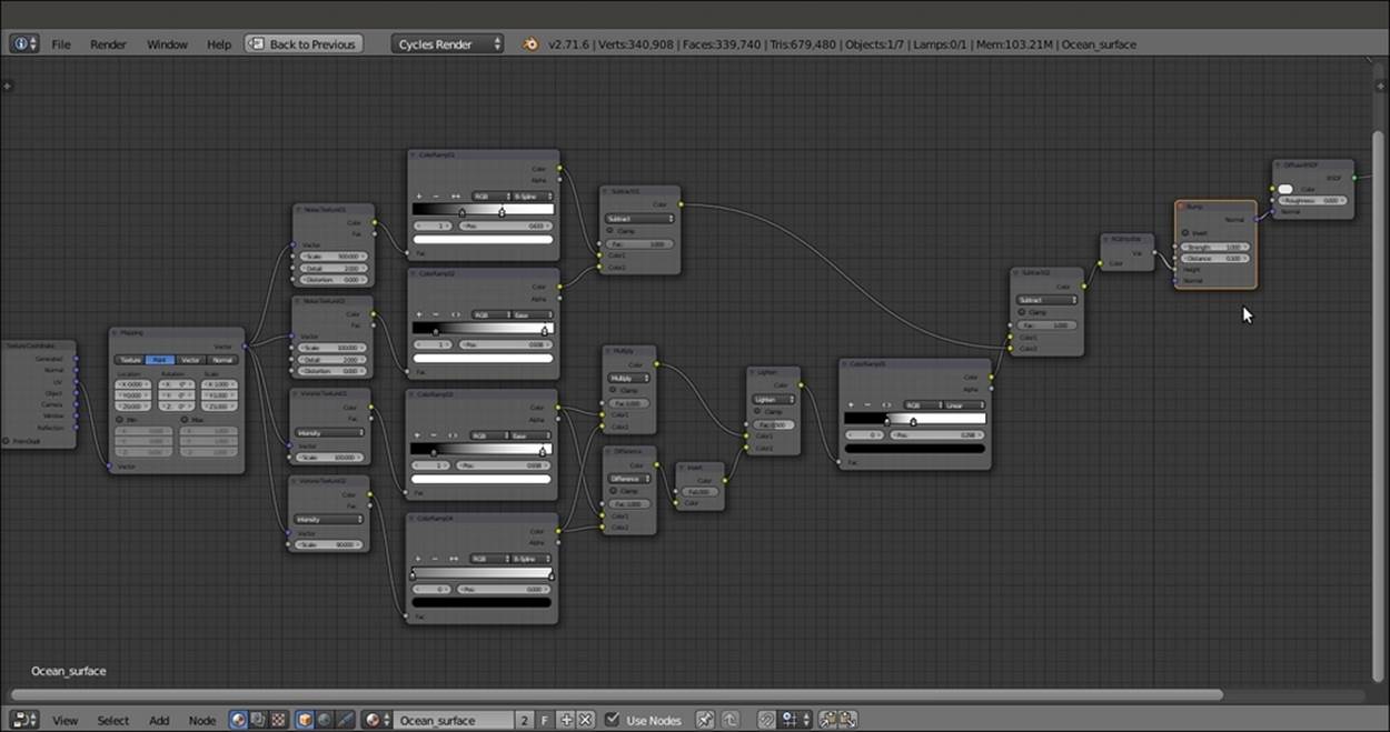
The network for the foam shader
17. Select all of these nodes and press Ctrl + G. Delete the Group Input node on the left.
18. Drag the BSDF output of the Diffuse BSDF shader onto the right side, to the empty socket of the Group Output node. Repeat this for the Color output of the Subtract02 node.
19. Press Tab to close the group. Rename it as Foam.
Creating the stencil material for the foam location
What we need now is a way to limit both the amount and the presence of the foam in the upper parts of the waves:
1. Add Gradient (press Shift + A and navigate to Texture | Gradient Texture) and Voronoi Texture (press Shift + A and navigate to Texture | Voronoi Texture) texture nodes, select them, and press Shift + D to duplicate them. Label them as Gradient Texture01,Gradient Texture02, Voronoi Texture03, and Voronoi Texture04.
2. Set the Gradient Types to Easing for both the nodes, the Scale value of the Voronoi Texture03 node to 250.000, and the Scale value of the Voronoi Texture04 node to 50.000.
3. Add three Mapping nodes (press Shift + A and navigate to Vector | Mapping, then press Shift + D to duplicate them). Label them as Mapping01, Mapping02, and Mapping03.
4. Add a Texture Coordinate node (press Shift + A and navigate to Input | Texture Coordinate) and a Geometry node (press Shift + A and navigate to Input | Geometry).
5. Connect the Normal output of the Geometry node to the Vector input of the Mapping01 node. Next, connect the Position output of the Geometry node to the Vector input of the Mapping02 node. Then connect the UV output of the Texture Coordinatenode to the Vector input of the Mapping03 node.
6. In the Mapping02 node, change the Location value of X to 0.500 and the Rotation value of Y to 90°.
7. Connect the output of the Mapping01 to the input of the Gradient Texture01, the output of the Mapping02 to the input of the Gradient Texture02, and the output of the Mapping03 to both the Vector inputs of the last two Voronoi Texture nodes.
8. Add a ColorRamp node (press Shift + A and navigate to Converter | ColorRamp), label it as ColorRamp06, and connect the Color output of the Voronoi Texture04 node to its Fac input. Set Interpolation to B-Spline. On the ColorRamp06 node, click on the little + icon to add a new color stop (medium gray) in the middle of the slider. Change its color to total black and move it to position 0.068.
9. Add a Math node (press Shift + A and navigate to Converter | Math), set the Operation to Multiply, and label it as Multiply02. Connect the Color output of the Gradient Texture02 node to the first Value input socket of the Multiply02 node.
10. Add a MixRGB node (press Shift + A and navigate to Color | MixRGB), set the Blend Type to Difference, and label it as Difference02. Set the Fac value to 1.000. Connect the Color output of the Gradient Texture01 to the Color1 input socket, and the Valueoutput of the Multiply02 node to the Color2 input socket of the Difference02 node.
11. Press Shift + D to duplicate the MixRGB node, set the Blend Type to Subtract, and label it as Subtract03. Connect the ColorRamp06 node's Color output to both the Color2 and to the Fac input sockets. Then connect the Color output of the Voronoi Texture03 node to the Color1 input socket.
12. Add a new ColorRamp node (press Shift + A and navigate to Converter | ColorRamp), label it as ColorRamp07, and connect the output of the Difference02 node to the Fac input. Then move the white color stop to position 0.344.
13. Duplicate one of the MixRGB nodes, set the Blend Type to Burn, and label it as Burn as well. Connect the Color output of the ColorRamp07 node to the Color1 input of the Burn node. Then connect the output of the Subtract03 node to the Color2 input socket of the Burn node as shown in the following screenshot:
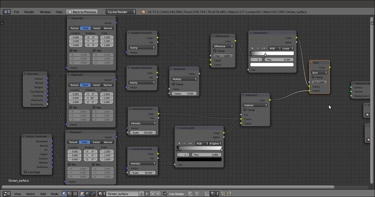
The stencil network
14. Now select all of these nodes, press Ctrl + G, and drag the Burn node output on the right to connect it to the empty socket of the Group Output node. Press Tab to close the group. Rename it as Foam_location.
Putting everything together
What is left now is just to connect these three groups to build the final shader:
1. Add a Mix Shader node (press Shift + A and navigate to Shader | Mix Shader). Label it as Mix Shader03 and connect its output to the Surface input socket of the Material Output node.
2. Connect the Shader output of the Ocean_water group to the first Shader input of the Mix Shader03. Then connect the BSDF output of the Foam group to the second Shader input.
3. Add two MixRGB nodes (press Shift + A and navigate to Color | MixRGB). Set the Blend Type of the first node to Multiply and the Fac value to 0.550. Then label it as Multiply03. Set the second node Blend Type to Burn and the Fac to 0.200. Then label it asBurn02.
4. Connect the Color output of the Foam_location group to the Color1 input of the Multiply03 node, and the Color output of the Foam group to the two Color2 inputs of both the Multiply03 and Burn02 nodes.
5. Connect the Multiply03 node's output to the Color1 input of the Burn02 node. Connect the output of the Burn02 node to the Fac input of the Mix Shader03 node as shown in the following screenshot:
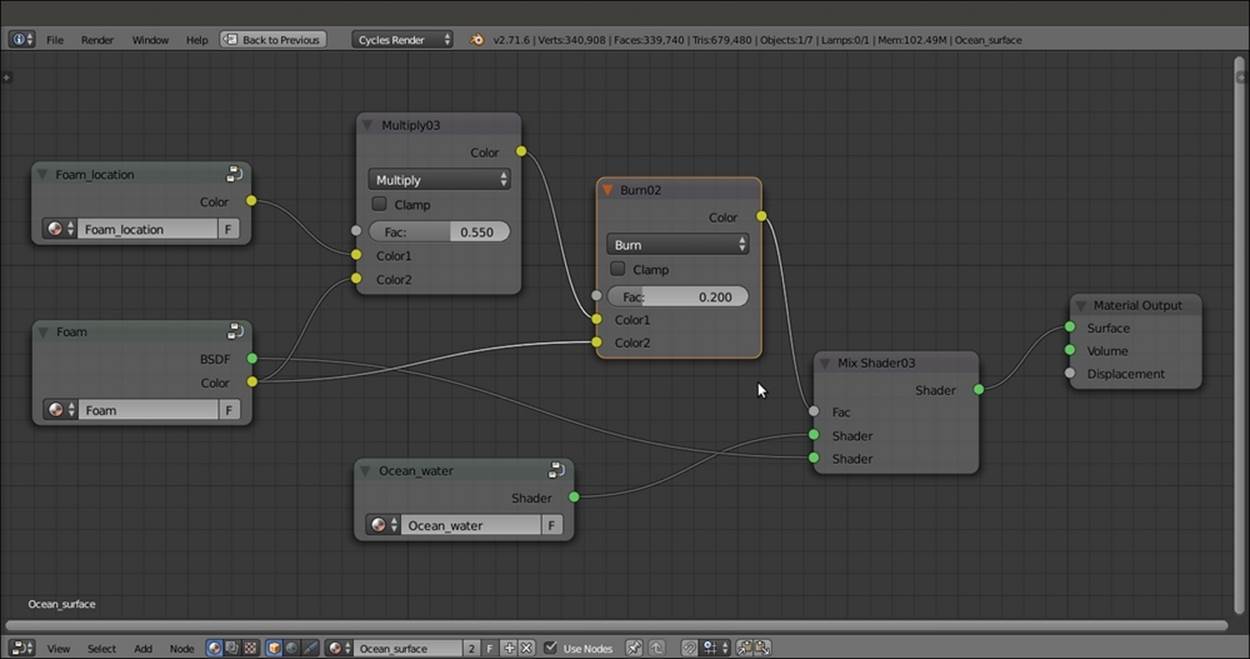
The overall view of the network with the connected node groups
How it works...
This material, which looks quite complex, is actually easily understandable by splitting the entire process in three stages corresponding to the three group nodes:
· In the first stage, we created the basic ocean water shader by mixing a Glass node with a Transparent BSDF shader on the ground of the Facing value of the Layer Weight node and then also with a Glossy BSDF shader driven by the index of refraction of water (the IOR value of the Fresnel node, which is 1.333 for water at 20°C). In other words, the ocean surface nicely reflects the environment but for the faces looking towards the Camera (the Facing factor), it is transparent. Very important is theBottom_ocean Plane, which is used to mimic the volume of the water and the underwater perspective and also emitting light to enhance the effect of the sun bouncing from the ocean surface to any floating object. The result of this first stage is shown in the following rendering:
Only the water shader rendered
· In the second stage, we created the material for the foam—a simple, white Diffuse BSDF shader. In fact, the peculiarity of the foam shader is mostly in the frothy bumpiness (and in the lacy-shaped outline cut by the procedural textures of the Foam_locationshader). Have a look at the rendered foam shader:
Only the foam shader rendered
· In the third stage, this group of nodes establishes the location of the foam that is mainly formed in the higher parts of waves in the real world, behaving as a gray-scale stencil map. Basically, a gradient texture is mapped on the Position (vertices) and multiplied for the Normal coordinates of the ocean mesh that, being created by the Ocean modifier, is constantly changing. So, only as the waves rise do they show foam at the top. This effect has been lessened and made a bit random to show some foam scattered around the rest of the surface as well. This works not only for stills but also in animation.
In the following screenshot, you can see the rendering of the resulting black-and-white mask that we used as a stencil for foam location (the image obtained by simply connecting the mask output to an Emission shader node to get a quick rendering and preview):
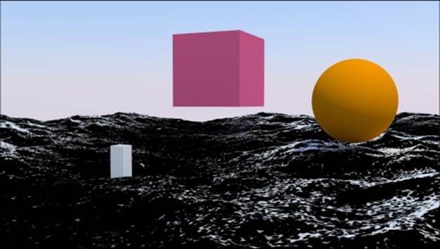
The only stencil material rendered
See also
The Blender Ocean modifier is able to create its own foam effect, generated as Vertex Colors and baked to a series of images (frames) saved in a directory. These images are then automatically mapped on the surface. They can be used as stencil masks instead of the Foam_location group node.
To know more about the Ocean modifier, you can take a look at the wiki documentation at http://wiki.blender.org/index.php/Doc:2.6/Manual/Modifiers/Simulate/Ocean.
Creating underwater environment materials
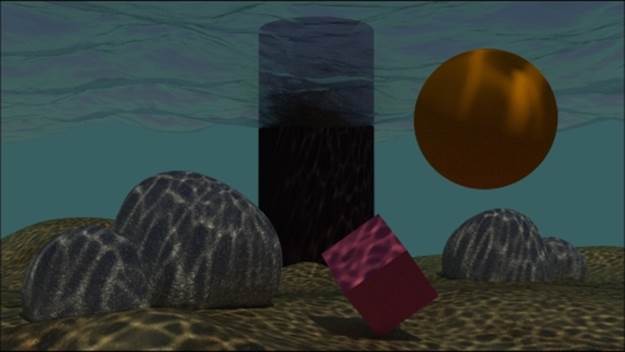
In this recipe, we will create an underwater environment as shown in the following screenshot, looking especially at a fake caustic effect projected by the water's wavy surface and from an atmospheric perspective, obtained by a per material dedicated node group:
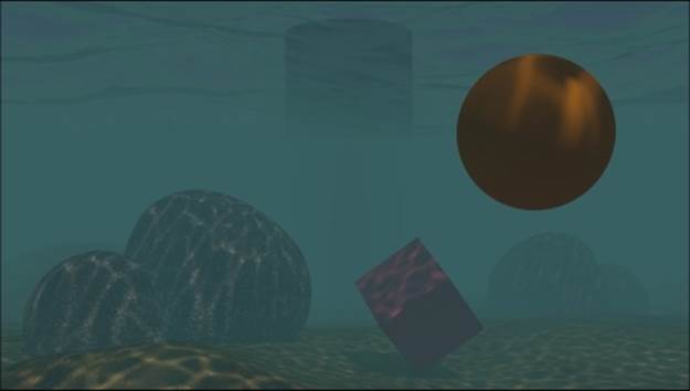
The underwater environment in the final rendering
Note
Note that this atmospheric perspective effect is actually a fake and it is not obtained by a volume material. Volumetric shaders will be explained in Chapter 9, Special Materials, of this Cookbook.
Getting ready
Let's start by preparing the scene:
1. Start Blender and switch to the Cycles rendering engine. Select the Cube and go to Edit Mode. Scale it 21 times bigger (Press A to select all the vertices, then press S, enter digit 21, and finally press Enter). Then scale it on the z axis of 0.230 (press S, then press Z, enter .23, and press Enter).
2. Go to the Top view (press 7 on the numeric keypad) and press Ctrl + R to add three edge loops along the global x axis. Then press Ctrl + R again to add three edge loops along the y global axis. The Cube is now subdivided into 16 equal parts.
3. Select all the faces, go to the Shading tab under the Tool Shelf panel to the left, and click on the Flip Direction button to invert the normals (which must look inwards).
4. Exit Edit Mode, switch to the Objects modifiers window, and assign a Subdivision Surface modifier. Set the type of subdivision to Simple and the Subdivisions to 4 both for the View and the Render levels.
5. Assign a second Subdivision Surface modifier. Again, set the type of subdivision to Simple but the Subdivisions to 2 for both the View and the Render levels.
6. Now assign an Ocean modifier. Set the values of Geometry to Displace, Spatial Size to 20, and Resolution to 12.
7. Go to the Tool Shelf again, and in the Edit subpanel under the Tools tab, click on the Smooth button below the Shading item.
8. Go to the Object data window and click on the + icon under the UV Maps subpanel to add a set of UV coordinates. There is no need to unwrap the Cube. Check the Double Sided item in the Normals subpanel at the top.
9. Make sure you are at frame 1, go to the Object modifiers window, and move the mouse over the Ocean modifier Time slot. Press the I key to add a key for the animation. Go to frame 25, change the Time value from 1.00 to 2.00, and press I again to set a second key.
10. In the Choose Screen layout button at the top, switch from Default to Animation. In the Graph Editor window, press T, and in the Set Keyframe Interpolation pop-up menu, select the Linear item under Interpolation. Then press Shift + E, and in the Set Keyframe Extrapolation pop-up menu, select the Linear Extrapolation item to make the ocean animation constant and continuous.
11. Rename the Cube as Ocean_surface as shown in the following screenshot:
The Cube with the assigned Ocean modifier
12. Move the Camera to a place below the ocean surface Set the Location value of X to 16.80000, Y to -2.64000, and Z to 0.95000. Then set the Rotation value of X to 92°, Y to 0°, and Z to 90°. Next, go to the Camera view (press 0 on the numeric keypad).
13. Add a Cube, a UV Sphere, and whatever other objects you want to add floating under the ocean surface. Assign them very simple and colored Diffuse BSDF materials. Add a big Cylinder to the background, close to the far side of the Ocean_surface object. Immerse half of it in water (and half will be in the air). Assign a simple Diffuse BSDF material to this item too. Smooth the Cylinder and the UV Sphere. If you wish, assign a Subdivision Surface modifier to the UV Sphere.
14. Now add a Plane. Place it at Location values of X as -3.22600, Y as -2.79600, and Z as -2.24463. Enter Edit Mode and scale it 30 times bigger (press A to select all of the geometry, then press S, enter 30 and press Enter). Using the Specials menu (press W) divide the Plane five or six times. Activate the PET (Proportional Editing Tool), randomly select vertices, and move them up to model the dunes of the ocean bed. Exit Edit Mode, smooth it by the Tools tab under the Tool Shelf panel, and assign aSubdivision Surface modifier at level 2. Disable the modifier visibility in the viewport by clicking on the eye icon. Rename it as Ocean_bed.
15. Add a Cube. In Edit Mode, divide it a couple of times (press W, and Subdivide Smooth), in Proportional Editing mode and by selecting vertices quickly model a big round rock. Replicate it three or four times by rotating and scaling the copies. Place them in a scattered manner on the Ocean_bed. Smooth it and assign a Subdivision Surface modifier. Disable the modifier visibility in the viewport.
16. Go to the World window and click on Use Nodes. Then click on the little square with a dot on the right side of the color slot. From the menu, select Sky Texture. Click on the Sky Type button above the little window and switch to the Preetham type.
17. Select the Lamp. In the Object data window, click on the Use Nodes button and set a yellowish color for the light (set the values for R to 1.000, G to 0.989, and B to 0.700). Change it to a Sun. Set the Size value to 0.010 and the Strength value to 2.500. Then set the Rotation values of X to 22°, Y to -7°, and Z to 144°. You might know that for a Sun Lamp, the location doesn't matter.
18. Go to the Render window. Under the Sampling subpanel, set the Clamp Direct and the Clamp Indirect values to 1.00. Then set the Samples to 25 for both Preview and Render. Under the Light Paths subpanel, disable both the Reflective Caustics andRefractive Caustics items.
As an alternative, just open the 9931OS_05_underwater_start.blend file and use the prepared scene.
How to do it...
First, let's perform the easy steps by appending the materials that are already made so that we can reuse them:
1. From the 9931OS_03_Rock_procedurals.blend file, append the Rock_proc01 material. Select the Rocks object and assign the newly appended material.
2. From the 9931OS_03_Ground.blend file, append the Ground_01 material. Select the Ocean_bed object and assign the material.
Now let's move on to the more complex steps:
1. From the 9931OS_05_Ocean.blend file, append the Ocean_surface object, material. Select the Ocean_surface object and assign the material. Rename it as Ocean_surface_under.
2. With the Ocean_surface object still selected, enter Edit Mode. Go to the Face selection mode and select only the upper faces. Then press Ctrl + I to invert the selection. In the Material window under the Properties panel, click on the + icon on the right (Add a new material slot), rename the new material as Null, and click on the Assign button. Now the Ocean_surface object has two different materials: the transparent water surface and the opaque sides and bottom (a simple white Diffuse BSDF material). ExitEdit Mode.
3. In the Material window, click on the Ocean_surface_under material to select it. In the Node Editor window, delete the Foam and the Foam_location node groups. Also delete the two MixRGB nodes. Just leave the Ocean_water node group connected to the second Shader input socket of the Mix Shader node, which in turn is connected to the Material Output node.
4. Add a Texture Coordinate node (press Shift + A and navigate to Input | Texture Coordinate), a Mapping node (press Shift + A and navigate Vector | Mapping), and an Image Texture node (press Shift + A and navigate to Texture | Image Texture). Connect the UV output of the Texture Coordinate node to the Vector input of the Mapping node, and the Vector output of this node to the Vector input socket of the Image Texture node.
5. In the Image Texture node, load the caustics_tileable_low.png texture and set the Color Space to Non-Color Data.
6. Add a Diffuse BSDF, a Transparent BSDF, and a Mix Shader node (press Shift + A and navigate to Shader | Diffuse BSDF, and repeat the same for the other two nodes). Label them as Diffuse_Caustics, Transparent_Caustics, and Mix Shader_Caustics.
7. Connect the Diffuse_Caustics node's output to the first Shader input socket of the Mix Shader_Caustics node, and the Transparent_Caustics output to the second Shader input socket. Then connect the Color output of the Image Texture node to theColor input socket of the Transparent_Caustics shader node, and the Alpha output of the Image Texture node to the Fac input of the Mix Shader_Caustics node.
8. Now connect the output of the Mix Shader_Caustics node to the first (and still empty) Shader input socket of the first Mix Shader node.
9. Add a Light Path node (press Shift + A and navigate to Input | Light Path). Connect the Is Camera Ray output to the Fac input of the first Mix Shader node. Add Frame (press Shift + A and navigate to Layout | Frame) and parent these last nodes to it. Then label it as FAKE_CAUSTICS as shown in the following screenshot:
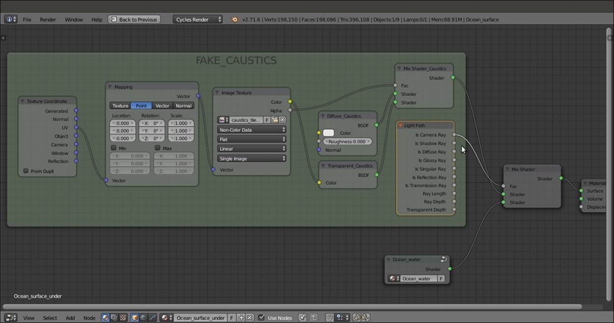
The FAKE_CAUSTICS frame mixed with the Ocean_Water node group on the ground of the Is Camera Ray output of the Light Path node
The following screenshot shows where we are so far:
The point where we are so far
What is missing now is the underwater atmospheric perspective effect. There are several ways to obtain this, for example, by compositing a Mist pass rendered in Blender Internal or by using a volumetric shader. However, we are going to do this with a simple node group added to every one of the different materials.
10. Add a Camera Data node (press Shift + A and navigate to Input | Camera Data), a Math node (press Shift + A and navigate to Converter | Math), an Emission node (press Shift + A and navigate to Shader | Emission), and a Mix Shader node (press Shift+ A and navigate to Shader | Mix Shader). Label the Mix Shader node as Mix Shader_Fog.
11. Connect the View Z Depth output of the Camera Data node to the first Value input of the Math node. Set the Math node's Operation to Multiply and the second Value to 0.030. Check the Clamp option. Connect the Multiply node output to the Fac input socket of the Mix Shader_Fog node.
12. Connect the Emission output to the second Shader input of the Mix Shader_Fog node. Set the Color values for R to 0.040, G to 0.117, and B to 0.124.
13. Select all the new nodes and press Ctrl + G to make a group. Click and drag the first Shader input socket of the Mix Shader_Fog node into the empty socket of the Group Input node on the left and repeat this step by connecting the Shader output socket on the right. Press Tab to close the group. Then rename it as Fog_underwater as shown in the following screenshot:
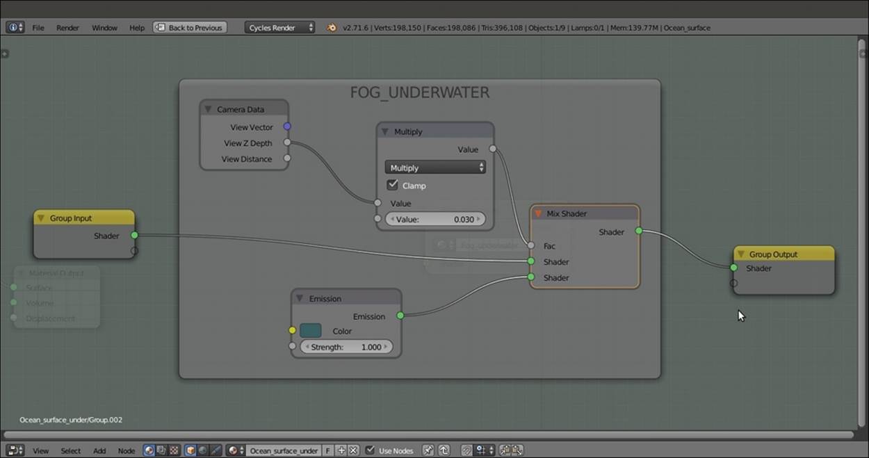
The FOG_UNDERWATER node group in Edit Mode
14. Add and paste the Fog_underwater node (press Shift + A and navigate to Group | Fog_underwater) just before the Material Output node of every material (in our scene, the Fog_underwater node will show eight users if the fake user button is selected) as shown in the following screenshot:
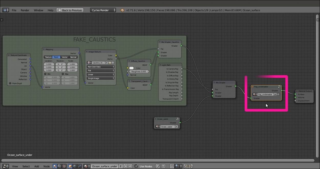
The Fog_underwater node group pasted at the end of the shader
How it works...
First of all, why should we choose a Cube for the ocean surface instead of the simpler Plane?
The reason is very simple: in Cycles, the World emits light, and the only way to avoid this is to set the color to pitch black (or by a combination of a Light Path node with the World materials, but this is another story). In our scene, the World is set to a bright blue sky color, and with a Plane, the underwater objects and the ocean bed would have been lit too much from the sides and the bottom the result look natural. A Cube, on the other hand, envelops all the underwater elements, limiting the lighting to the Sun Lamp passing through the surface, and projecting the image textured caustics. This gives a more natural-looking result.
The image texture we assigned to the water material is used to obtain a textured transparency effect. Right now, the water surface is actually opaque and transparent according to the black and white values of the textures, so as to allow the Sun Lamp light to pass through and project the caustics.
Thanks to the Is Camera Ray output of the Light Path node, the caustics image texture is not directly renderable on the ocean surface, but it nevertheless has some effect on the other materials. Because the value of Is Camera Ray is 1, the rays starting from the Camera and directly hitting the ocean surface can render only the clean water material plugged into the second input socket of the Mix Shader node, while the transmitted caustics (plugged in the first Shader socket = 0) get rendered.
The Fog_underwater node group is simply an emitter material serving as the background (deep green in this case) and mapped on every underwater material according to the z depth of the Camera (it also works with the Camera frame, in the viewport). The density of the fog is set by the Multiply node's second Value. For the ocean body, a value of 0.030 is good enough.
Note
The Camera z axis must not be confused with the global coordinate z axis, which is the vertical blue line visible in the 3D view. The Camera z axis, on the other hand, is the ideal line connecting the starting point of view to any visible element in the scene.
Note that we didn't expose the values of the nodes in the Fog_underwater group. This is because in Edit Mode, we can tweak the internal values of just one node to automatically update all the fog group instances assigned to the other materials. Besides, we know that the values exposed on the group interface would overwrite the internal settings and work only for that single node instance.
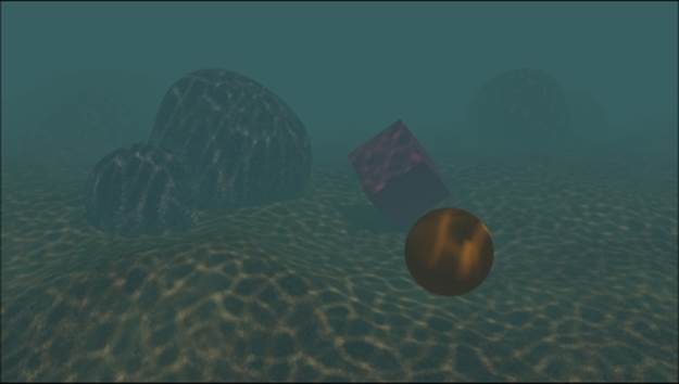
The final underwater environment rendered from a different point of view
Creating a snowy mountain landscape with procedurals
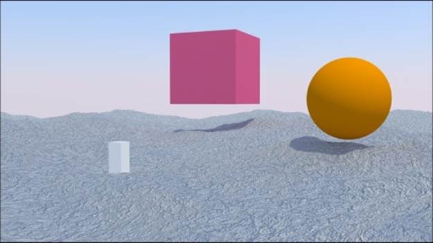
In this recipe, we will make a snowy mountain landscape by reusing existing shaders—the Rock_procedural and the Snow materials. We will improve these materials by grouping them and exposing the useful values. Then we will create a new group node that will work as a stencil to depict snow in a more customizable and natural way on the rocks as shown in the following screenshot:
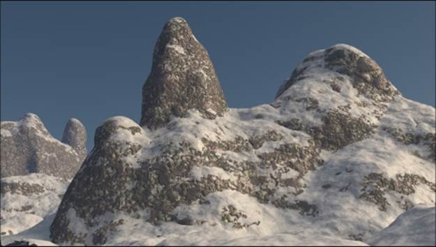
The snowy mountain landscape as it appears in the final rendering
Getting ready
As usual, let's start with the preparation of the scene. In this case, we start with an almost ready blend file:
1. Start Blender and open the 9931OS_05_RockSnow_start.blend file, where there is a scene with a placed Camera—a simply modeled Mountain object and a Plane set as Emitter.
2. Select the Mountain object, go to the Object modifiers window, and assign a Subdivision Surface modifier. Set the levels to 2 for both View and Render.
3. Assign a second Subdivision Surface modifier. Set the levels to 1 for both View and Render.
4. Assign a Displace modifier. Click on the Show texture in texture tab to the extreme right of the Texture name slot to go to the Textures window. Assign a Voronoi procedural texture. Set the Size to 1.00. Go back to the Displace modifier and set theStrength to -0.200.
5. Assign a second Displace modifier. In the Texture window, assign a new Voronoi Texture and set Distance Metric to Manhattan and Size to 0.50. Back in the Displace modifier panel, set the Strength to -0.050.
6. Assign a third Displace modifier, select a Clouds texture, and set Noise to Hard and the Displace modifier's Strength to 0.040.
7. Assign a fourth Displace modifier. In the Texture window, assign a Musgrave procedural texture. Set the Type to Hetero Terrain, Dimension to 0.650, Lacunarity to 2.000, Octaves to 0.500, Offset to 0.250, Basis to Voronoi F1, and Size to 2.00. Back in theDisplace modifier panel, set the Strength to 0.300.
8. Assign a fifth Displace modifier. In the Texture window, assign a Distorted Noise texture. Set the Noise Distortion to Voronoi F1, Basis to Improved Perlin, Distortion to 2.000, and Size to 3.30. Back in the Displace modifier panel, set the Strength to0.100 as shown in the following screenshot:
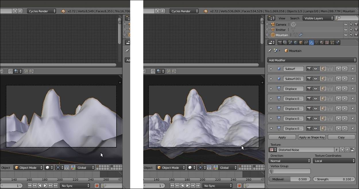
The mountain object obtained using different settings—without and with the several modifiers
9. Now disable the Display modifier in viewport button (the eye icon) of each modifier.
10. Go to the World window and click on the Use Nodes button. Then click on the little square with a dot on the right side of the Color slot. From the pop-up menu, select Sky Texture. On the Background node, set the Strength value to 1.200.
11. Add a Mix Shader node (press Shift + A and navigate to Shader | Mix Shader) and paste it between the Background and the World Output nodes. Switch the link of the Background node with the second input socket.
12. Add a Texture Coordinate node (press Shift + A and navigate to Input | Texture Coordinate), a Mapping node (press Shift + A and navigate to Vector | Mapping), an Environment Texture node (press Shift + A and navigate to Texture | Environment Texture), and a new Background node (press Shift + A and navigate to Shader | Background).
13. Connect the Generated output of the Texture Coordinate node to the Vector input socket of the Mapping node, and the output of this node to the Vector input socket of the Environment Texture node. Connect the Color output of this node to the Colorinput socket of the second Background node.
14. Connect the output of the second Background node to the first input socket of the Mix Shader node, and set its Strength to 0.250. Add a Light Path node (press Shift + A and navigate to Input | Light Path). Connect the Is Camera Ray output to the Facinput socket of the Mix Shader node.
15. Go to the Environment Texture node and click on the Open button. Browse to the texture folder and load the WinterForest_Env.hdr image (it's a free, high-dynamic-range image downloaded from the sIBL Archive at http://www.hdrlabs.com/sibl/archive.html, and licensed under the Creative Commons Attribution-NonCommercial-ShareAlike 3.0 License).
16. Go to the Mapping node and set the Rotation value of Z to 19° as shown in the following screenshot:
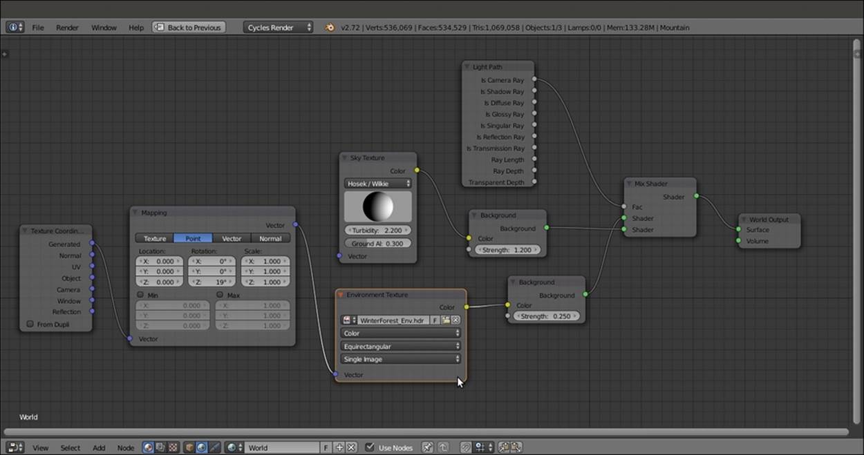
The World network setting
17. Go to the Render window, and under the Sampling subpanel, set both the Clamp Direct and Clamp Indirect values to 1.00. Set the Samples to 10 for Preview and 25 for Render. Under the Light Paths subpanel, disable both the Reflective Caustics andRefractive Caustics items and set the Filter Glossy to 1.00.
How to do it...
We are going to create the scene and materials by dividing the process into four stages:
· Appending and grouping rock and snow shaders
· Mixing the material groups
· Creating a stencil shader
· Adding an atmospheric perspective
So, let's start with the first stage.
Appending and grouping the rock and the snow shader
Let's append the required (and previously made) materials, and group them for convenience:
1. From the 9931OS_03_snow.blend file, append the Snow_01 material, and for now, assign it to the Mountain object.
2. In the Node Editor window, select all the nodes except Texture Coordinates and Material Output, and press Ctrl + G to group them.
3. Place the SNOW_COLOR frame to the right of the SNOW_BUMP frame. Select the Group Output node, and in the (press N) Properties panel of the Node Editor window, delete the Value output.
4. Add a Bump node (press Shift + A and navigate to Vector | Bump). Connect the Value output of the Math04 node inside the SNOW_BUMP frame to the Height input socket of the Bump node. Then connect the Normal output of the Bump node to theNormal input sockets of the Diffuse BSDF, Glossy BSDF, and Translucent BSDF shaders inside the SNOW_COLOR frame.
5. Click on the Strength socket of the Bump node and drag it into the empty socket on the Group Input node. Rename the socket (automatically named Strength) as Bump_Strength. Repeat this step for the Distance socket and rename it as Bump_Distance.
6. Drag the Color input socket of the Diffuse BSDF node into the empty socket of the Group Input node. Move the new socket to the top of the list and rename it as Snow_Color. Drag the Color input of the Glossy BSDF shader node and connect it to the sameSnow_Color socket.
7. Drag the Color input socket of the Translucent BSDF node into the empty socket of the Group Input node. Move the new socket upwards, just below the Snow_Color socket, and rename it as Transl_Color.
8. Move the Vector socket on the Group Input node to the bottom of the list, and close the group. Rename it as Snow_02 and check the fake user option. Click on the Bump_Strength slider and type 1.500 as shown in the following screenshot:
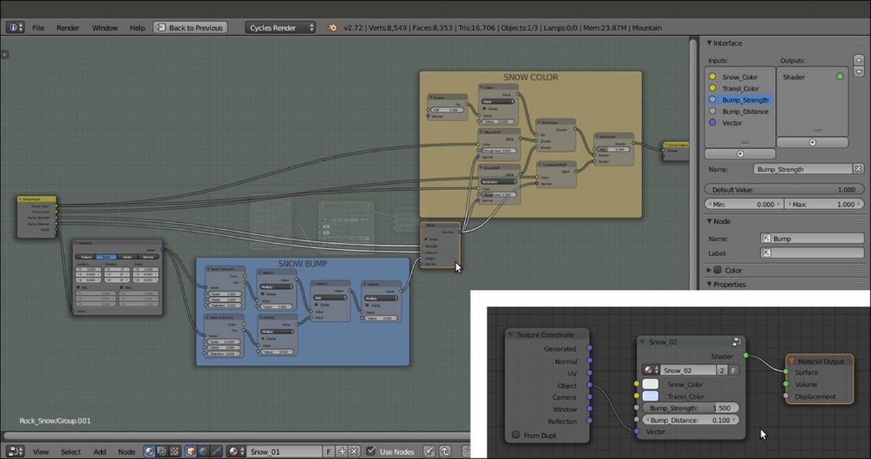
Making a node group of the appended snow material
9. From the 9931OS_03_Rock_procedurals.blend file, append the Rock_proc01 material. Go to the Material datablock button on the Node Editor toolbar and assign it to the Mountain object.
10. In the Node Editor window, select all the nodes except the Texture Coordinates and the Material Output nodes. Press Ctrl + G to group them. Set the Location values in the Mapping node to 0.000 for all the three axes.
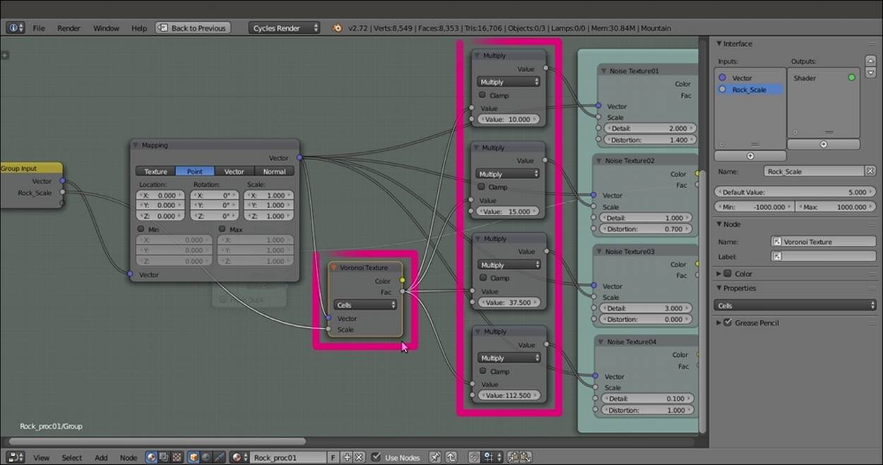
11. Add a Math node (press Shift + A and navigate to Converter | Math). Set the Operation to Multiply and the first Value to 1.000. Press Shift + D to duplicate it, and do this three times. Connect the Value outputs of each of the four Multiply-Math nodes to theScale input sockets of the four Noise Texture nodes inside the BUMP frame.
12. Now, in the second Value slot of each Multiply-Math node, set 10.000 for Noise Texture01, 15.000 for Noise Texture02, 37.500 for Noise Texture03, and 112.500 for Noise Texture04.
13. Add a Voronoi Texture node (press Shift + A and navigate to Texture | Voronoi Texture), switch the Coloring to Cells, and connect its Fac output to the first Value input socket (the socket with value of 1.000) of each of the four Multiply-Math nodes.
14. Connect the Voronoi Texture node's Vector input socket to the Vector output of the Mapping node and drag the link from its Scale input socket to the empty socket of the Group Input node. Rename the new socket as Rock_Scale as shown in the following screenshot:
Adding Math nodes to tweak the exposed scale values of the textures for the procedural rock material
15. Now go to the COLOR frame and delete the RGB node. Then select the Mix03 node and press Ctrl + X to delete it, maintaining the connection of the Darken node to the Color2 socket of the Add node.
16. Add a MixRGB node (press Shift + A and navigate to Color | MixRGB), label it as Mix03 again, and paste it between the RGB Curves node and the Diffuse BSDF shader. Set the Blend Type to Color and connect its output to the Color input socket of theGlossy BSDF shader.
17. Press Shift + D to duplicate the Mix03 node. Label the duplicate as Mix04 and paste it between the RGB Curves and the Mix03 nodes. Set its Blend Type to Multiply and the Color2 to pure black. Then select both the Mix03 and Mix04 nodes and parent them to the COLOR frame as shown in the following screenshot:
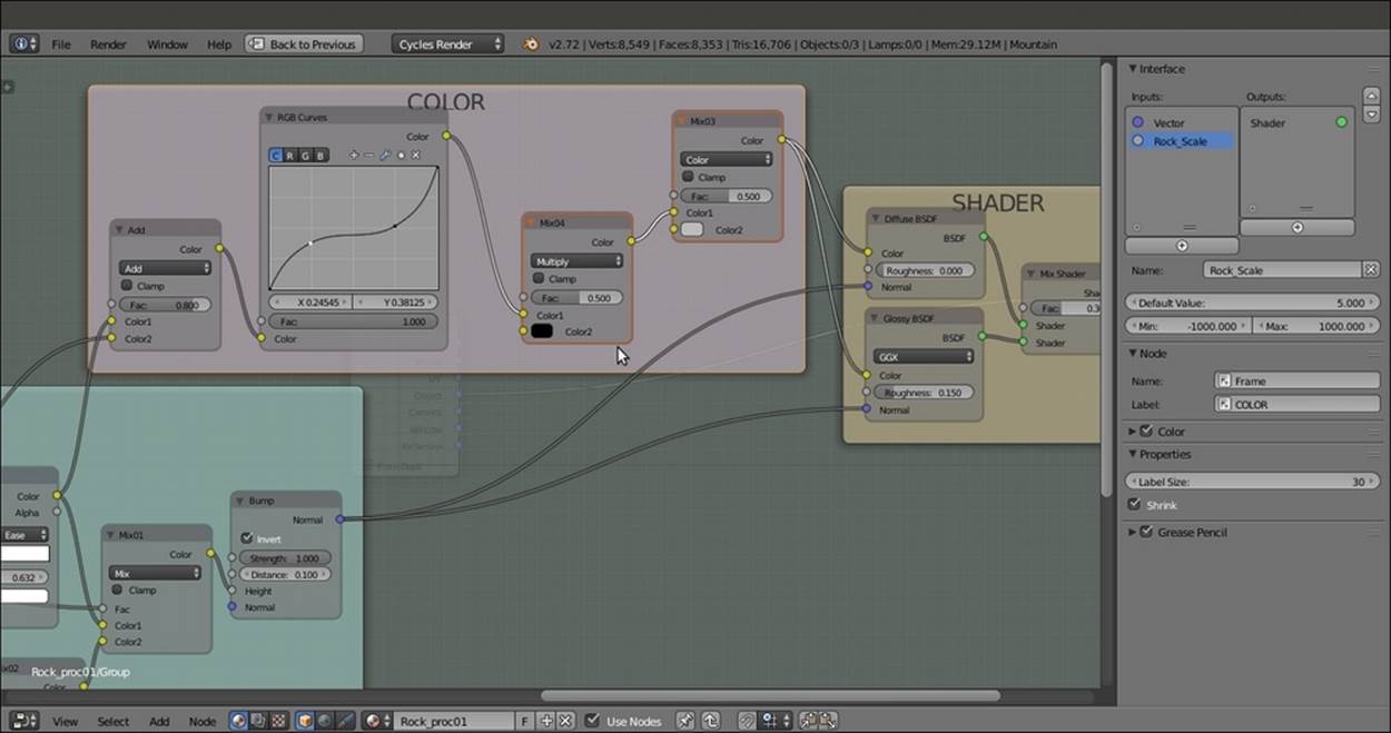
Adding color variations to the rock material
18. Click on the Color2 input socket of the Mix03 node. Drag it to the empty socket of the Group Input node. Move the new socket to the top of the list and rename it as Rock_Color.
19. Repeat the preceding step with the Fac socket of the Mix04 node, and rename the new socket as Rock_Darkness. Move the Vector socket on the Group Input node to the bottom of the list.
20. Add a new MixRGB node (press Shift + A and navigate to Color | MixRGB) and a ColorRamp node (press Shift + A and navigate to Converter | ColorRamp). Connect the Color output of the Mix03 node to the Color1 input socket of the new MixRGB node, and the Color output of Mix01 to the Color2 input socket.
21. Connect the Color output of the new MixRGB node to the Fac input socket of the ColorRamp node. Then connect the Color output of this node to the empty socket of the Group Output node. Go to ColorRamp and set the position of the black color stop to0.500 and the position of the white color stop to 0.545 as shown in the following screenshot:
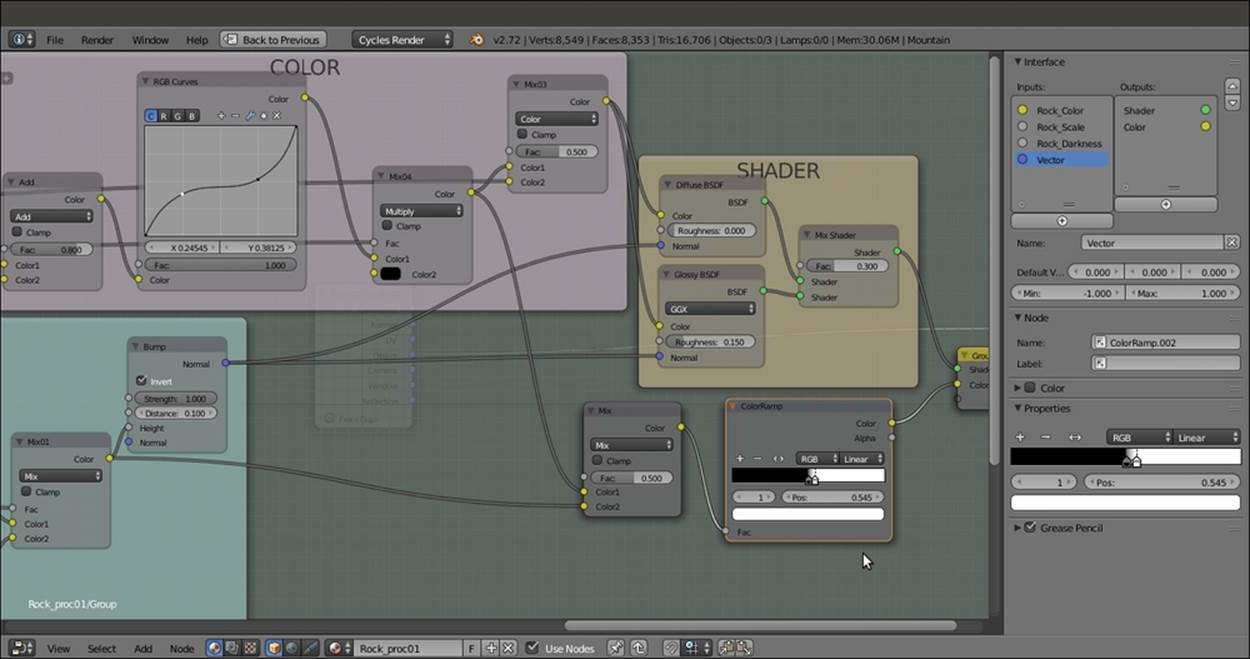
Creating a Color output in the node group to be used later to detail the stencil effect
22. Drag the Strength and the Distance sockets of the Bump node to the Group Input node, and rename them as Bump_Strength and Bump_Distance, respectively. Move the Vector socket to the bottom. Press Tab to exit Edit Mode.
23. Rename the group as Rock_proc_02, and enable the fake user. Set the Rock_Color values for R 0.078, G to 0.067, and B to 0.056; the Rock_Scale to 0.600; and the Rock_Darkness to 0.469 as shown in the following screenshot:
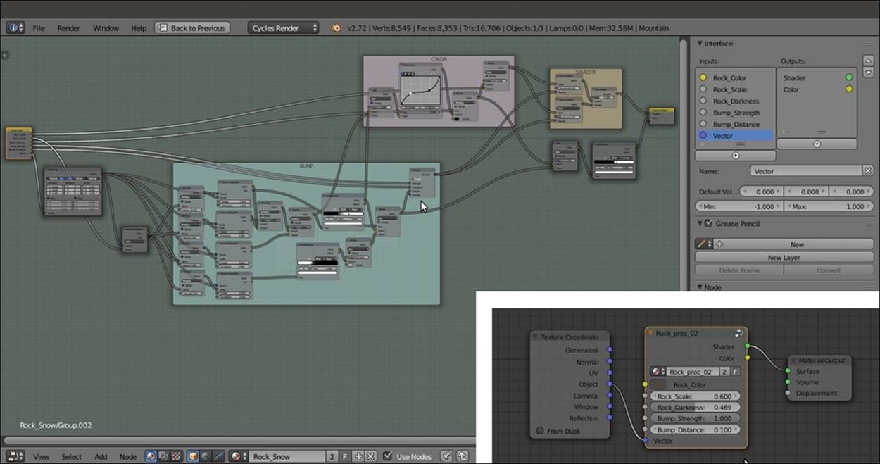
The overall view of the procedural rock node group in Edit Mode
Mixing the material groups
Now we can start to build the real shader by mixing the procedural rock and snow materials:
1. Press Shift + A with the mouse in the Node Editor window and add the Snow_02 group node (press Shift + A and navigate to Group | Snow_02). Then rename the material as Rock_Snow in the Node Editor toolbar.
2. Add a Mix Shader node (press Shift + A and navigate to Shader | Mix Shader) and paste it between the Rock_proc_02 group node and the Material Output node. Connect the Shader output of the Snow_02 group node to the second Shader input socket of the Mix Shader node.
3. Connect the Object output of the Texture Coordinate node to the Vector input socket of the Snow_02 group node as shown in the following screenshot:
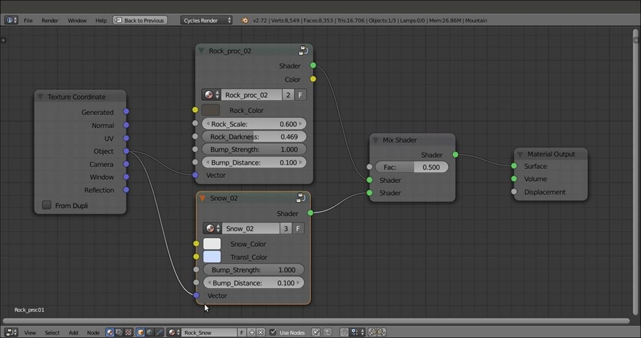
Starting to build the snowy rock mountain material
Creating the stencil shader
At this point, both the materials are assigned to the Mountain object, but if you render the preview now, they will appear on the whole mesh surface as a mixture of rock and snow. We must build a separator to establish where the surface will show only the rock and where it will show only the snow:
1. Add a Geometry node (press Shift + A and navigate to Input | Geometry), two Mapping nodes (press Shift + A and navigate to Vector | Mapping), two Gradient Texture nodes (press Shift + A and navigate to Texture | Gradient Texture), and aColorRamp node (press Shift + A and navigate to Converter | ColorRamp).
2. In the Properties panel of the Node Editor, label these four nodes as follows: Mapping01, Mapping02, Gradient Texture01, Gradient Texture02, and ColorRamp01. Connect the Normal output of the Geometry node to the Vector input socket of the Mapping01 node and the Position output to the Mapping02 node. Then connect the Mapping01 node to the Gradient Texture01 node and the Mapping02 node to the Gradient Texture02 node.
3. Leave the Gradient Type of the Gradient Texture01 node as Linear and set the Gradient Type of the Gradient Texture02 to Quadratic. In the Mapping01 node, set the Location value of X as -0.210 and the Rotation value of Y as 90°. In the Mapping02node, set only the Rotation value of Y as 90°.
4. Add three MixRGB nodes (press Shift + A and navigate to Color | MixRGB). Set the Fac of the first one to 0.000 and label it as Add01. Then connect the Color outputs of both the Gradient Texture nodes to the Color1 and to the Color2 input sockets.
5. Connect the output of the Add01 node to the Fac input socket of the ColorRamp01 node. Then set its Interpolation to B-Spline and move the black color stop to 0.600 position. Add a new color stop, set the color to pure black, and move it to the 0.700position. Then move the position of the white color stop to 0.800.
6. Label the other two MixRGB nodes as Burn01 and Burn02. Connect the Color output of the ColorRamp01 node to the Color1 input socket of the Burn01 node, and the Color output of this node to the Color1 input of the Burn02 node. Set the Blend Typefor both the nodes to Burn.
7. Add a Frame (press Shift + A and navigate to Layout | Frame) and parent all of these nodes to it. Label the frame as SLOPE as shown in the following screenshot:
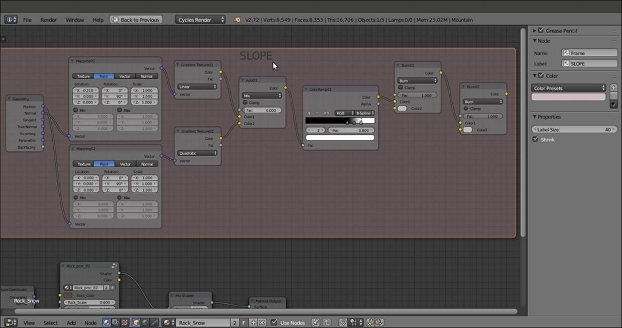
The SLOPE frame
8. Now press Shift + D to duplicate one of the Mapping nodes (press Alt + P to unparent it from the frame), and move it to under the SLOPE frame. Label it as Mapping03 and change the Location value of X to -0.600.
9. Add a Noise Texture, a Voronoi Texture, and a Musgrave Texture node (press Shift + A and navigate to Texture | Noise Texture, repeat the same for all other nodes) and place them in a column next to the Mapping03 node. Set the Noise Texture node'sScale value to 4.600. Set the Voronoi Texture node's Coloring to Cell and the Scale to 28.700. Set the Musgrave Texture node's type to Ridged Multifractal, the Scale to 3.500, Detail to 16.000, Dimension to 0.900, Lacunarity to 0.600, Offset to 0.500, andGain to 5.000.
10. Connect the Vector output of the Mapping03 node to the Vector inputs of the three textures. Then add a MixRGB node (press Shift + A and navigate to Color | MixRGB), set the Blend Type to Burn, and label it as Burn03.
11. Connect the Fac outputs of the Noise Texture and Voronoi Texture nodes to the Color1 and Color2 input sockets of the Burn03 node. Press Shift + D to duplicate the Burn03 node, label it as Burn04, and set its Fac value to 1.000. Connect the Color output of the Burn03 node to the Color1 input socket of the Burn04 node. Then connect the Fac output of the Musgrave Texture node to its Color2 input socket.
12. Add a ColorRamp node (press Shift + A and navigate to Converter | ColorRamp), label it as ColorRamp02, and paste it between the Burn03 and the Burn04 nodes. Set Interpolation to Ease and move the white color marker to the 0.487 position.
13. Add a Frame (press Shift + A and navigate to Layout | Frame), select all of these nodes and then the frame, and press Ctrl + P to parent them. Label the frame as DENSITY as shown in the following screenshot:
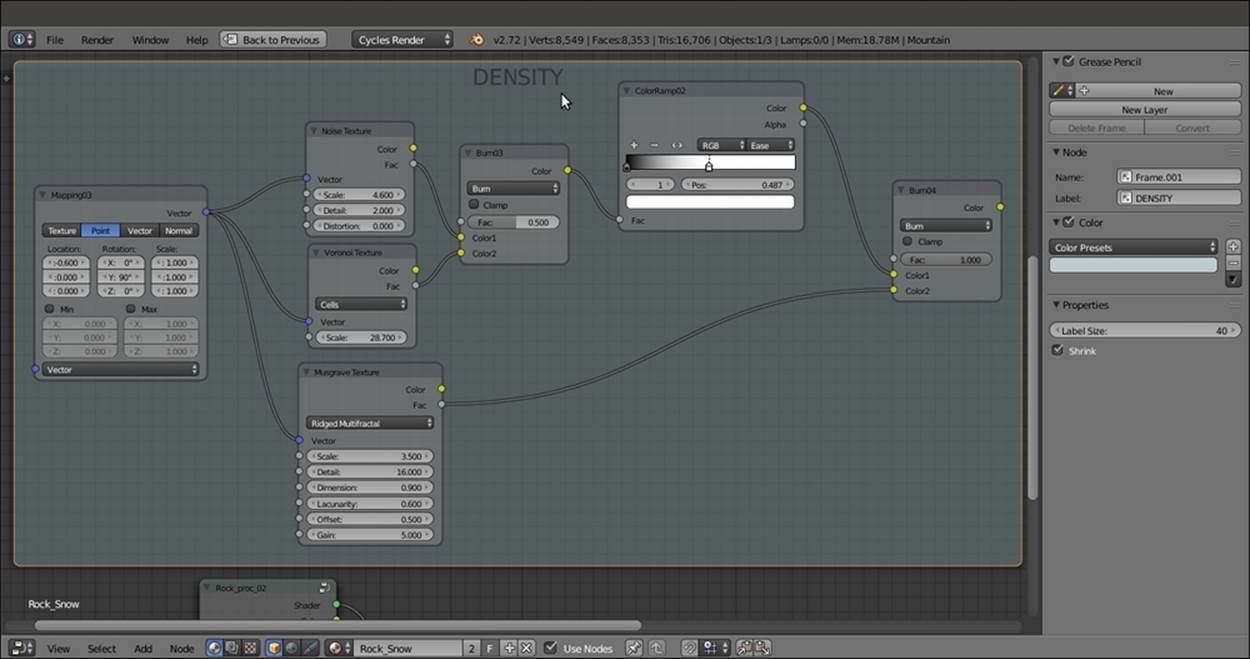
The DENSITY frame
14. Box-select the two frames (with all the nodes inside) and press Ctrl + G to create a group. Add a MixRGB node (press Shift + A and navigate to Color | MixRGB), set the Blend Type to Soft Light, and set the Fac value to 1.000. Connect the Color output of the Burn02 node inside the SLOPE frame to the Color1 input socket. Then connect the Color output of the last Burn04 node inside the DENSITY frame to the Color2 input socket.
15. Drag the Color output of the Soft Light node into the empty socket of the Group Output node to create a new Color output on the interface. Then add a new ColorRamp (press Shift + A and navigate to Converter | ColorRamp), label it as ColorRamp04, and paste it between the Soft Light and the Group Output nodes. Set Interpolation to Ease, the black color stop to the 0.500 position, and the white color stop to the 0.600 position.
16. Go to the SLOPE frame. Click and drag the Fac socket of the Add01 node to the empty socket of the Input Group node. Rename the new input as Snow_amount.
17. Go to the DENSITY frame and attach the Vector input of the Mapping03 node to the empty socket of the Input Group node. Move it up by clicking on the little arrow icon in the Properties panel, and press Tab to close the group. Rename it as Separator as shown in the following screenshot:
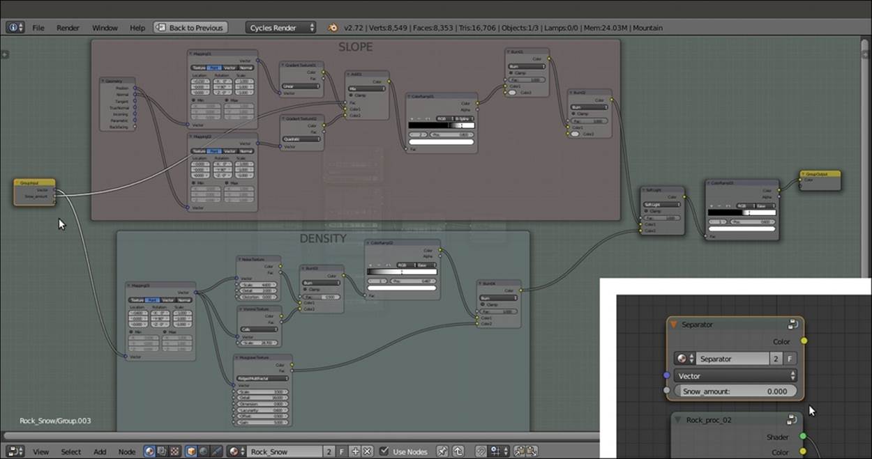
The outputs of the SLOPE and DENSITY frames added inside the Separator node group
18. Connect the Object output of the Texture Coordinate node to the Vector input socket of the Separator node group. For the rendering of the image at the beginning of this recipe, I've set the Snow_amount value to 0.724.
19. Add one more MixRGB node (press Shift + A and navigate to Color | MixRGB), set the Blend Type to Add, and connect the Color output of the Separator group node to the Color1 input socket. Then connect the Color output of the Rock_proc_02 group node to the Color2 input socket. Set the Fac value to 1.000 and connect the Color output to the Fac input socket of the Mix Shader node.
Adding the atmospheric perspective
The final step we can do to improve our material is to append the Fog_underwater node group, from the 9931OS_05_underwater_final.blend file located in Nodetree. Rename this node Atmos_persp and paste it just before the Material Output node. Then press Tab to open the group by entering Edit Mode. Set the Multiply node value to 0.010 and the color values of the Emission shader for R to 0.078, G to 0.133, and B to 0.250 as shown in the following screenshot:
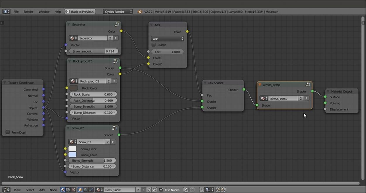
The overall network and the atmospheric perspective node group added at the end of the shader. Note the Color output of the Rock material added to the output of the Separator to work as stencil or blending factor.
How it works...
Now let's see how this material actually works, by dividing the creation's process into three parts:
· Firstly, we appended the Snow material and made a group, exposing the required properties and changing the way the bump works. In other words, we deleted the output to the Displacement input of the Material Output node and implemented a per shader bump.
This doesn't really make a big difference in the final rendering. Just be aware that a bump piped in the Displacement socket can react to Ambient Occlusion (which we didn't use in the scene, by the way), but this is not true with the per shader bump.
· Secondly, we appended the Rock_procedural material and made a group of it as well. Again, all the necessary values were exposed, and although we kept the material unaltered in this scene, the group could now be easily reused for different kinds of rock in other projects or on different objects.
We added a Math node set to Multiply for every texture Scale value that needed to be driven by one single exposed input. The first Value of the Math node, set to the original scale value, gets multiplied by the driven second Value, thus increasing or decreasing (for values smaller than 1.000) the final scale value.
· Thirdly, we built Separator, a node group outputting gray-scale values that are connected to the Fac input of the Mix Shader node, which works as a stencil map, separating the two different materials on the mesh surface accordingly to black and white values. The two gradient textures in the SLOPE frame, mapped on the position and the normals of the mesh and then blended together by the Burn nodes, make the snow material (the white color value of the stencil map) appear more on the mesh's faces that have more a horizontal trend than a vertical one. Thanks to the Add01 node, mixing the gradients driven by the exposed input Snow_amount and influencing the gradient of the ColorRamp01 node, it's also possible to set the quantity of snow (the white color in the stencil) on the whole object. The mixed textures in the DENSITY frame make the separation line between black and white more frayed and realistic, and so also the Color output of the Separator group that is added to a Color output of the Rock shader just before being connected to the Fac input of the Mix Shader. Have a look at the following screenshot:
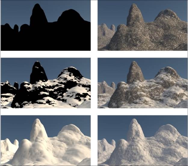
The only mask and the Rendered versions of three different values of the Snow_amount slider
In the preceding set of screenshots, you can see the different effects of the 0.000, 0.700, and 1.000 values of the Snow_amount slider. The black-and-white mask works as a separator between the rock and the snow materials.
Creating a realistic Earth as seen from space
In this recipe, we will create a realistic Earth as shown in the following screenshot, using both image textures from the Web and some procedurals:
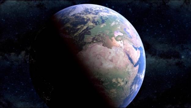
The Earth as it appears in the final rendering
Getting ready
The image textures provided with this Cookbook have generally been heavily down-scaled and are good for demonstration purposes only (in this case, for a very distant Earth render). For better results with this recipe, replace these low-resolution images with high-resolution versions that you can find at these addresses:
· http://www.shadedrelief.com/natural3/pages/textures.html
· http://www.shadedrelief.com/natural3/pages/clouds.html
· http://celestia.h-schmidt.net/earth-vt/
· http://www.celestiamotherlode.net/catalog/earth.php
Before you download anything, always take a look at the license of the images provided by any site you can find to ensure that they are released as freely usable, especially if you are going to use them for commercial work. All the preceding links should be okay, but on the Internet, things can change quite quickly, so double-check!
You will need at least five image maps for this recipe: Earth-color, the color of the land or sea in daylight; Earth-night, the color of the land or sea at night (usually provided with superimposed city lights); Earth-bump, a gray-scale, high map of the continents; Earth-spec, an outline with the continents in black and the water masses perfectly white; and Clouds, a gray-scale map of the clouds as shown in the following screenshot:
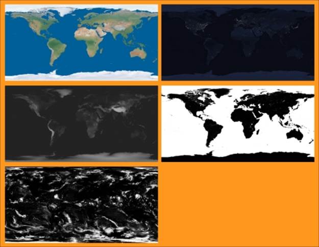
The five image textures
Actually, Cycles can handle very big textures pretty well, even 16 K images (that is, images made by 16.000 pixels for the longest side), so you can use them at the best resolution you can find. Be aware that the bigger the resolution of the textures, the longer the rendering times, especially if they are used as bump maps.
Now perform the following steps:
1. Start Blender and switch to the Cycles Render engine.
2. Delete the default Cube and add a UV Sphere (with the mouse arrow in the 3D view, press Shift + A and navigate to Mesh | UV Sphere). In the Outliner, rename it as Earth_Surface.
3. With the mouse arrow in the Camera view, press the 1 key on the numeric keypad to go to the Front view. Then press the 5 key to switch to Orthogonal. Next, press Tab to enter Edit Mode, followed by A to select all the vertices. Finally, press U. In the UV Mapping pop-up menu, select Sphere Projection. Then exit Edit Mode.
4. Make sure you place the 3D Cursor at the center of the UV Sphere. Then add an Empty (press Shift + A and navigate to Empty | Arrows). In the Object data window, set its Size to 2.00 and rename it as Empty_terminator. Go to the Object Constraintswindow and assign a Damped Track constraint to the Empty_terminator. In the Target field, select the Sun item (the Lamp), and in the To field, click on the X button.
5. Reselect the UV Sphere and go to the UV Maps subpanel under the Object data window. Click on the + icon button to add a new UV coordinates layer. Rename it as UVMap_terminator.
6. Go to the Object modifiers window and assign a Subdivision Surface modifier first, followed by a UVProject modifier. For this modifier, in the UV Map field, select the UVMap_terminator item. In the Object to use as projector transform field, select theEmpty_terminator.
7. Press Shift + D and press Enter to duplicate the Earth_Surface object. In the Transform subpanel under the Properties panel to the right (press N if this is not activated), set the Scale value for X, Y, and Z to 1.001. Rename it as Earth_Clouds.
8. Duplicate it again, set the Scale value to 1.002, and rename it as Earth_Atmosphere.
9. Add a new Empty (press Shift + A and navigate to Empty | Plain Axes) and rename it as Empty_Earth. In the Object data window, set its Size to 2.00. Press Shift and select the Earth_Surface, Earth_Clouds, Earth_Atmosphere, and the Empty_Earthobjects. Press Ctrl + P and click on Object to parent the three UV Spheres to Empty_Earth.
10. Select Empty_Earth, and in the Transform panel, set the Rotation values of X to 18.387°, Y to 0.925°, and Z to -4.122° (you can obviously rotate the Empty_Earth as you wish, but this helps provide a nice point of view on the specular effect showing on the oceans).
11. Select the Camera, and in the Transform panel, set the Location values of X to -0.64000, Y to -4.70000, and Z to 0.12000. Then set the Rotation values of X to 89°, Y to 0°, and Z to -9°. Go to the Object data window and change the Focal Length to 60.000(millimeters). Press the 0 key on the numeric keypad to go to the Camera view.
12. Go to the World window and change the background Color to pure black.
13. Select the Lamp and change it to a Sun. Set the Size to 0.050 and the Strength to 10.000. Set the Color values for R to 1.000, G to 0.902, and B to 0.679. In the Transform panel, set the Location values of X to 158.00000, Y to -27.00000, and Z to 107.00000. ForRotation, set X to 1.5°, Y to 56°, and Z to -8° (Sun lamps don't need a location, but in this case, we need it to establish a target for a later-to-come day/night terminator trick).
14. Go to the Render window. Under the Sampling subpanel, set the Clamp Direct and Clamp Indirect values to 1.00, the Preview samples to 20, and the Render samples to 50.
15. Go to the Scene window. In the Color Management subpanel, click on the Use Curves item. Set the Exposure value to 1.000. Then click inside the curve window to add a new point, and place it at position X as 0.61149 and Y as 0.71250. Then set the value of the B channel for the White Level between 0.800 and 0.850.
How to do it...
After the creation of the 3D scene and the setting of the lighting, let's go for the materials, starting with the planet's surface.
The planet surface
In the Outliner (just temporarily), hide the Earth_Clouds and Earth_Atmosphere objects by clicking on the little eye icons to the right side of the names. This is to see only the Earth_Surface in the viewport, rendered and updated in real time as we work on the material:
1. Select the Earth_Surface object. Click on the New button in the Material window under the Properties panel or in the Node Editor toolbar. Rename the material as Surface.
2. In the Material window under the main Properties panel, switch the Diffuse BSDF shader with a Mix Shader node. In the first Shader slot, load a new Diffuse BSDF shader and set its Roughness value to 1.000. In the second Shader slot, load a Glossy BSDF node. Then set its Roughness value to 0.700 and Distribution to Beckmann. Set the Fac value of the Mix Shader to 0.100.
3. Press N in the Node Editor window to open the Active Node panel. Label the shaders as Diffuse_Lands and Glossy_Lands and the Mix Shader as Mix Shader_Lands.
4. Add an Image Texture node (press Shift + A and navigate to Texture | Image Texture) and connect its Color output to both the Color input sockets of the Diffuse_Lands and Glossy_Lands shaders. Click on the Open button on the Image Texture node, browse to your textures directory, and load the Earth-col_low.png image (or a high-resolution version, if available). Label the image node as Color_Day.
5. Add a new Image Texture node (press Shift + A and navigate to Texture | Image Texture) and a Bump node (press Shift + A and navigate to Vector | Bump). Connect the Color output of this Image Texture node to the Height input socket of the Bumpnode. Then connect the Normal output of the Bump node to the Normal input sockets of both the Diffuse_Lands and the Glossy_Lands nodes.
6. Label the second Image Texture node as Bump. Then click on its Open button and load the Earth-bump_low.png image. Set the Color Space to Non-Color Data. Label the Bump node as Bump_Lands and set the Strength value to 0.020.
7. Add a MixRGB node (press Shift + A and navigate to Color | MixRGB) and paste it between the Color_Day and the Diffuse_Lands nodes. Set the Blend Type to Color, the Fac value to 0.300, and the Color2 value for R to 0.072, G to 0.127, and B to 0.578.
8. Add a Frame (press Shift + A and navigate to Layout | Frame). Press Shift and select the two image texture nodes (Color_Day and Bump), the Color node, Bump_Lands node, Diffuse_Lands and Glossy_Lands shaders, and then the Frame. Press Ctrl +P to parent them. Label the Frame as LANDS as shown in the following screenshot:
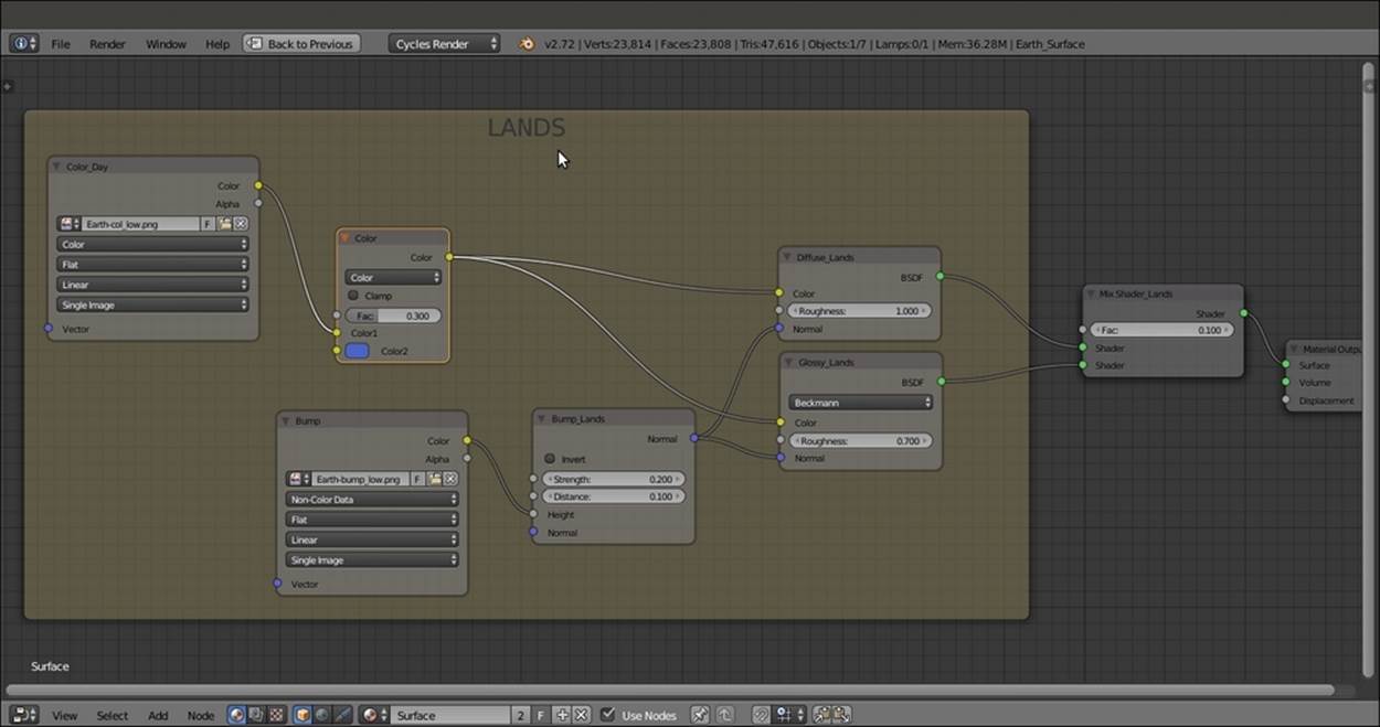
The LANDS frame
9. Now add a Noise Texture node (press Shift + A and navigate to Texture | Noise Texture), a Bump node (press Shift + A and navigate to Vector | Bump), a Diffuse BSDF shader (press Shift + A and navgiate to Shader | Diffuse BSDF), and a Glossy BSDF shader (press Shift + A and navigate to Shader | Glossy BSDF).
10. Set the Noise Texture node's Scale value to 1000.000 and connect its Color output to the Height input socket of the Bump node. Label this node as Bump_Seas, set the Strength value to 0.015, and connect its Normal output to the Normal input sockets of the new Diffuse BSDF and Glossy BSDF shaders. Label them as Diffuse_Seas and Glossy_Seas and set the Glossy BSDF node's Roughness value to 0.150.
11. Add a Frame (press Shift + A and navigate to Layout | Frame). Press Shift and select the new nodes and then the Frame. Press Ctrl + P to parent them. Rename the frame as SEAS.
12. Add a Mix Shader node (press Shift + A and navigate to Shader | Mix Shader), label it as Mix Shader_Seas, and place it just under the Mix Shader_Lands node. Set the Fac value to 0.100. Connect the output of the Diffuse_Seas node to the first Shaderinput, and the output of the Glossy_Seas node to the second Shader input socket.
13. Press Shift + D to duplicate the Mix Shader_Seas node and paste it between the Mix Shader_Lands and the Material Output nodes. Label it as Mix Shader_Surface. Connect the output of the Mix Shader_Seas node to its second Shader input socket.
14. Add a new Image Texture node (press Shift + A and navigate to Texture | Image Texture) and rename it as Spec/mask. Connect its Color output to the Fac input socket of the Mix Shader_Surface node. Click on the Open button to load the Earth-spec_low.pngimage. Set the Color Space to Non-Color Data.
15. Add a Frame (press Shift + A and navigate to Layout | Frame). Press Shift and select the Spec/mask node and then the Frame. Press Ctrl + P to parent them. Rename the frame as SEPARATOR LANDS/SEAS.
16. Now click on the Color output of the Color_Day image texture inside the LANDS frame, and drag it so that it is connected to the Color input of the Diffuse_Seas shader node inside the SEAS frame.
17. Add a MixRGB node (press Shift + A and navigate to Color | MixRGB) to the SEAS frame (just add it and parent it to the frame). Paste it just before the Diffuse_Seas shader. Switch the Color1 connection to the Color2 input socket. Then set the Color1values for R to 0.002, G to 0.002, and B to 0.022.
18. Add a ColorRamp node (press Shift + A and navigate to Converter | ColorRamp) to the SEAS frame and label it as ColorRamp01. Connect the Color output to the Color input of the Glossy_Seas shader. Set Interpolation to B-Spline. Change the black color stop (index 0) to pure white and the white color stop values (index 1) for R to 0.072, G to 0.127, and B to 0.578, with Alpha value set to 0.000. Move it to 0.150 position. Click on the + icon button to add a new color stop. Change its Color values for R to 0.965, Gto 0.462, B to 0.223, and Alpha to 1.000. Move it to 0.075 position.
19. Add a Layer Weight node (press Shift + A and navigate to Input | Layer Weight) to the SEAS frame. Connect the Facing output to the Fac input socket of the ColorRamp01 node and the Fac input socket of the MixRGB node. Set the Blend factor to 0.200as shown in the following screenshot:
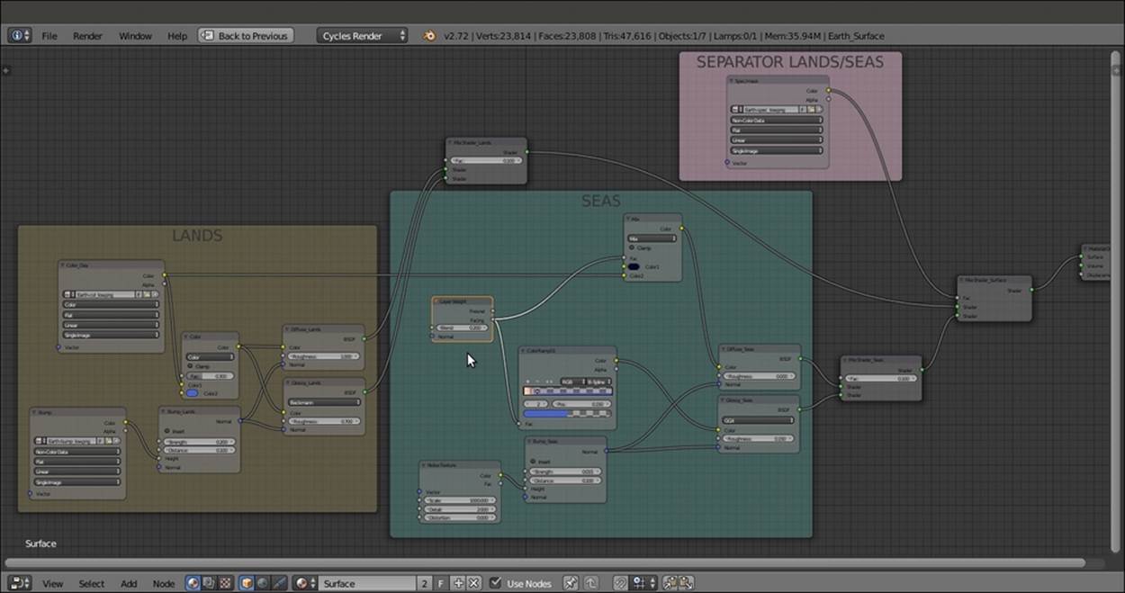
The LANDS and the SEAS frames connected and separated by the simple SEPARATOR LANDS/SEAS
20. Add an Image Texture node (press Shift + A and navigate to Texture | Image Texture), a ColorRamp node (press Shift + A and navigate to Converter | ColorRamp), a MixRGB node (press Shift + A and navigate to Color | MixRGB), and an Emissionshader (press Shift + A and navigate to Shader | Emission). Label the Image Texture node as Color_Night and the ColorRamp as ColorRamp02.
21. Connect the Color_Night node's Color output to the Fac input socket of the ColorRamp02 node, and the Color output of this node to the Color1 input socket of the MixRGB node. Then connect the MixRGB node's output to the Color input of the Emissionnode.
22. In the Color_Night image texture node, load the Earth-night_low.png image. Set the ColorRamp02 node's Interpolation to B-Spline and move the black color stop to 0.250 position. Then move the white color stop to the 0.495 position. Set the MixRGB node'sBlend Type to Multiply, the Fac value to 0.700 and the Color2 values for R to 1.000, G to 0.257, and B to 0.090. Set the Emission node's Strength value to 1.000.
23. Add a Frame (press Shift + A and navigate to Layout | Frame). Press Shift to select these new nodes and then the Frame. Press Ctrl + P to parent them. Rename the frame as NIGHT. This is shown in the the following screenshot:
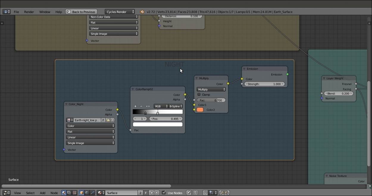
The NIGHT frame
24. Add an Attribute node (press Shift + A and navigate to Input | Attribute), a Gradient Texture node (press Shift + A and navigate to Texture | Gradient Texture) and a ColorRamp node (press Shift + A and navigate to Converter | ColorRamp). Connect theVector output socket of the Attribute node to the Vector input socket of the Gradient Texture node, and the Color output of this node to the Fac input socket of the ColorRamp node.
25. In the Name slot of the Attribute node, write UVMap_terminator. Set the ColorRamp node's Interpolation to B-Spline. Then move the black color stop to 0.500 and the white color stop to the 0.000 position. Click on the + icon button to add a new color stop. Set its color to pure black as well.
26. Add a Frame (press Shift + A and navigate to Layout | Frame). Press Shift to select these three nodes and then the frame. Press Ctrl + P to parent them. Rename the frame as TERMINATOR.
27. Add a Mix Shader node (press Shift + A and navigate to Shader | Mix Shader), label it as Mix Shader_Terminator, and paste it just between the Mix Shader_Lands and the Mix Shader_Surface nodes. Connect the output of the Emission node inside theNIGHT frame to its second Shader input socket, and the Color output of the ColorRamp inside the TERMINATOR frame to its Fac input socket as shown in the following screenshot:
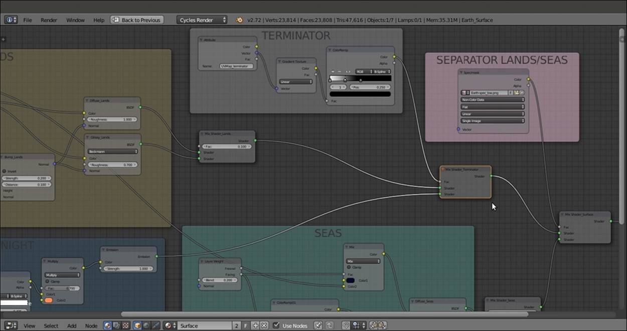
The TERMINATOR frame added to the surface material network
The clouds
As second planet material, let's go with the clouds by performing the following steps:
1. Now go to Outliner, unhide the Earth_Clouds sphere, and select it. Click on New in the Material window under the main Properties panel or in the Node Editor toolbar. Rename the material as Clouds.
2. In the Material window under the main Properties panel, switch the Diffuse BSDF shader with a Mix Shader node. Label it as Mix Shader_Clouds, and in the first Shader slot, load a Transparent BSDF shader. In the second Shader slot, load a new Diffuse BSDF shader. Set the color of both the shaders to pure white.
3. Add an Image Texture node (press Shift + A and navigate to Texture | Image Texture) and a Bump node (press Shift + A and navigate to Vector | Bump).
4. Label the Image Texture node as Clouds and the Bump node as Bump_Clouds. Connect the Bump node's output to the Normal input of the Diffuse_Clouds node. Set the Strength value to 0.020.
5. Click on the Open button of the Clouds image texture node and load the Clouds_low.png image. Set the Color Space to Non-Color Data.
6. Press Shift + D to duplicate the Clouds image node. Then add a Texture Coordinate node (press Shift + A and navigate to Input | Texture Coordinate) and a Mapping node (press Shift + A and navigate to Vector | Mapping). Connect the UV output of theTexture Coordinate node to the Mapping node, and the output of this node to the Vector input socket of the duplicated Clouds image texture node.
7. Add a MixRGB node (press Shift + A and navigate to Color | MixRGB) and connect the output of both the two Clouds image texture nodes to the Color1 and Color2 input sockets. Set the Blend Type to Add and the Fac value to 1.000. Connect the Coloroutput to the Height input socket of the Bump_Clouds node and to the Fac input socket of the Mix Shader_Clouds node.
8. In the Mapping node, set the Rotation values of X to 32°, Y to 17°, and Z to 5°.
9. Add a Frame (press Shift + A and navigate to Layout | Frame). Press Shift to select the nodes and then the Frame. Then press Ctrl + P to parent them. Rename the frame as CLOUDS. This is shown in the screenshot:
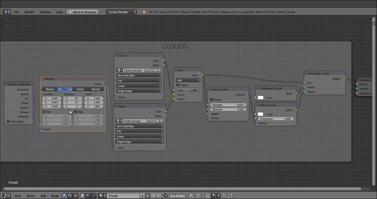
The CLOUDS material
The atmosphere
The third planet material is the atmosphere layer:
1. In Outliner, unhide the Earth_Atmosphere sphere and select it. Click on New in the Material window under the main Properties panel or in the Node Editor toolbar. Rename the new material as Atmosphere.
2. In the Material window on the right, under the main Properties panel, switch the Diffuse BSDF shader with a Mix Shader node. Label it as Mix Shader_Atmos1, and in the first Shader slot, load a Transparent BSDF shader (label it Transparent_Atmos1). In the second Shader slot, load a Diffuse BSDF shader (label it Diffuse_Atmos1).
3. Add a Layer Weight node (press Shift + A and navigate to Input | Layer Weight) and a ColorRamp node (press Shift + A and navigate to Converter | ColorRamp). Connect the Facing output of the Layer Weight node to the Fac input of the ColorRamp(label it ColorRamp03). Set the ColorRamp03 node's Interpolation to B-Spline, move the black color stop to the 0.395 position, and set the Alpha value to 0.000. Set the color of the white color stop (index 1) for R to 0.072, G to 0.127, and B to 0.578.
4. Connect the Color output of the ColorRamp03 node to the Color input socket of the Diffuse_Atmos1 node, and the Alpha output to the Fac input of the Mix Shader_Atmos1 node. Set the Layer Weight node's blend factor to 0.500.
5. Add a Frame (press Shift + A and navigate to Layout | Frame). Press Shift to select these nodes and then the Frame. Then press Ctrl + P to parent them. Rename the frame as ATMOSPHERE.
6. Add an Attribute node (press Shift + A and navigate to Input | Attribute), a Gradient Texture node (press Shift + A and navigate to Texture | Gradient Texture), and a ColorRamp node (press Shift + A and navigate to Converter | ColorRamp). Connect the Vector output socket of the Attribute node to the Vector input socket of the Gradient Texture node, and then the Color output of this node to the Fac input socket of the ColorRamp (label it ColorRamp04).
7. In the Name slot of the Attribute node, type UVMap_terminator. Set the ColorRamp04 node's Interpolation to B-Spline. Then move the black color stop to the 0.400 position and the white color stop to the 0.600 position, but change this stop's color to black as well. Click on the + icon button to add a new color stop. Set its color to pure black and move it to the 0.450 position. Click on the + icon button again to add a new color stop. Set its color to pure black and move it to the 0.550 position. Set the Alpha of all the four black color stops to the 0.000. Click once more on the + icon button to add a new color stop. Set its color values for R to 1.000, G to 0.047, and B to 0.005. Set Alpha value to 0.100 and move it to the 0.500 position.
8. Add a Mix Shader node (press Shift + A and navigate to Shader | Mix Shader), a Transparent BSDF node (press Shift + A and navigate to Shader | Transparent BSDF), and an Emission node (press Shift + A and navigate to Shader | Emission). Label them as Mix Shader_Atmos2, Transparent_Atmos2, and Diffuse_Atmos2.
9. Connect the Transparent_Atmos2 node's output to the first Shader input socket of the Mix Shader_Atmos2 and the Diffuse_Atmos2 output to the second Shader input. Then connect the Color output of the ColorRamp04 node to the Color input socket of the Diffuse_Atmos2 node and the Alpha output to the Fac input socket of the Mix Shader_Atmos2 node.
10. Add a Frame (press Shift + A and navigate to Layout | Frame). Press Shift to select these nodes and then the Frame. Then press Ctrl + P to parent them. Rename the frame as RED_TERMINATOR.
11. Add a final Mix Shader node (press Shift + A and navigate to Shader | Mix Shader), label it as Mix Shader_Atmos3, and set the Fac value to 0.950. Connect the output of the RED_TERMINATOR frame to the first Shader input socket and the output of theATMOSPHERE frame to the second Shader input socket. Then connect the output of the Mix Shader_Atmos3 node to the Surface input socket of the Material Output node as shown in the following screenshot:
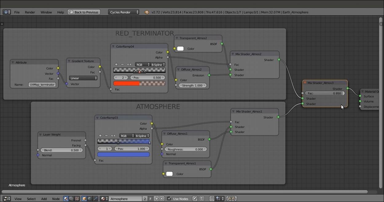
The RED_TERMINATOR and the ATMOSPHERE frames
How it works...
The three overlapping UV Spheres technique is quite old, and (at least for what relates to Blender) dates back to almost 2004—more precisely to the How to make a realistic planet in Blender(2004) tutorial I wrote at that time for Blender version 2.23/2.30 (http://www.enricovalenza.com/rlpl.html). That tutorial is now outdated, but the technique and basic concepts still work, even in Cycles. Hence, we get the planet surface on the smaller of the spheres, a clouds layer on a slightly bigger sphere, and the envelopingatmospheric Fresnel effect on the biggest sphere.
We divided the material creation process into the three stages, corresponding to the three layers/spheres. First, we built the more complex of all the three shaders that is the Surface material:
· From step 1 to step 8, we built the shader for the continents—simple image textures connected as color factors to a Diffuse BSDF and Glossy BSDF shaders. From step 9 to step 13, we made the basic shader for the oceans.
· In steps 14 and 15, we split the continents component from the oceans using the Earth-spec map, a black-and-white image working as a stencil for the factor input of the Mix Shader_Surface node. We also connected the Earth-color map to the SEAS diffuse shader to bring color back to the oceans.
· From step 16 to step 19, we added a ColorRamp node to the SEAS frame, driven by a Facing fresnel node. This was done to enhance the color of the water's specularity (according to what NASA's satellite photos often show). A deep blue color was mixed with the color image map by a MixRGB node. Thanks to the Facing fresnel node, the blue color was mapped on the mesh faces perpendicular to the point of view, resulting in darker water masses towards the center of the Earth sphere.
· From step 20 to step 23, we built the night shader. The Earth-night image was clamped (contrasted) by a ColorRamp node, and the resulting brightness values were multiplied by a reddish color in the MixRGB node. All of this was then assigned to anEmission shader. The night side of the Earth surface shows only in the shadow part of the sphere thanks to the Empty_terminator trick.
· From step 24 to step 27, we built the day/night terminator stencil.
· Then, from step 28 to step 36, we built the Clouds layer on the second sphere. We added more variety to the single Clouds_low.png image by superimposing and offsetting (the mapping rotation of) a copy of the same cloud image.
· From step 37 to step 47, we built the Atmosphere layer on the third (bigger) sphere, with the Fresnel atmospheric effect and the reddish terminator.
As you have probably noticed, we didn't use any Texture Coordinate or Mapping nodes to map the image maps. This is because the UV Spheres had been unwrapped with Image Texture nodes. The existing UV coordinate layer was automatically taken into account by Cycles for the mapping.
For the ocean bump, which was obtained by the Noise procedural, the Generated mapping option was automatically used.
Thanks to the Damped Track constraints, which were targeted to the position of the Sun lamp, we could use the Empty_terminator object as a UV coordinates projector for the day/night division on the planet surface and for the red colored transition zone (the red terminator) in the Atmosphere layer.
All materials on the site are licensed Creative Commons Attribution-Sharealike 3.0 Unported CC BY-SA 3.0 & GNU Free Documentation License (GFDL)
If you are the copyright holder of any material contained on our site and intend to remove it, please contact our site administrator for approval.
© 2016-2026 All site design rights belong to S.Y.A.