Blender Cycles: Materials and Textures Cookbook, Third Edition (2015)
Chapter 6. Creating More Complex Man-made Materials
In this chapter, we will cover the following recipes:
· Creating cloth materials with procedurals
· Creating a leather material with procedurals
· Creating a synthetic sponge material with procedurals
· Creating a spaceship hull shader
Introduction
In this chapter, we will see some more complex artificial materials, starting with the relatively simpler materials. Remember that the procedure is basically the same as that for all the materials we have seen so far—the generic shader followed by the color pattern or the bump effect (one or more), depending on the preponderance of the different components.
The only difference is the level of complexity they can reach (for example, look at the Creating a spaceship hull shade recipe at the end of this chapter).
Creating cloth materials with procedurals
In this recipe, we will create a generic cloth material, as shown in the following screenshot:
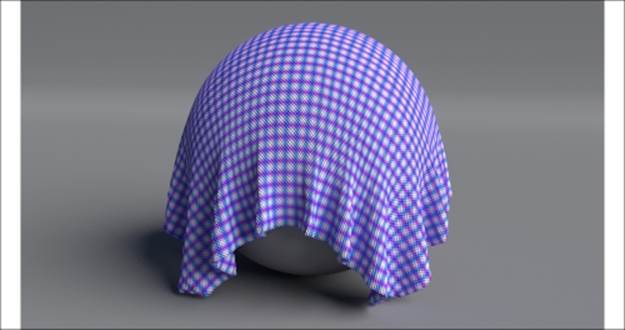
The cloth material as it appears in the final rendering
Getting ready
Before we start creating the material, let's set up the scene by performing the following steps:
1. Start Blender and load the 9931OS_cloth_start.blend file. In the scene, there is already a cloth simulation.
2. Click on the Play animation button in the Timeline toolbar (or press Alt + A) to see the simulation running and being cached in real time. It consists of a Plane (our fabric) draped on a UV Sphere leaning on a bigger Plane (the floor).
3. After the simulation has been totally cached (a total of 100 frames), in the Physics window (the last tab to the right) under the Cloth Cache tab, press the Current Cache to Bake button to save the simulation. The 100-frame simulation is now cached and saved inside a folder (unless differently specified), named as a blend file, and stored on your hard drive in the same directory as the blend file.
From now on, there is no need to perform calculations about the simulation anymore. Blender will read the simulation data from that cache folder, so it will be possible to quickly scroll through the Timeline bar and immediately reach any frame inside the cached range.
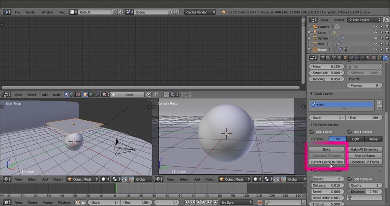
The cloth simulation scene with the Cloth Cache subpanel to the right
How to do it...
Now we are going to create the material on the fabric Plane, which has been first unwrapped by assigning a basic UV layer (Object data | UV Maps) and later subdivided by the Specials menu. This is done before the cloth simulation by performing the following steps:
1. Go to the 100 frame.
2. Make sure you have the fabric Plane selected. Click on New in the Material window under the main Properties panel or in the Node Editor window. Rename the new material cloth_generic.
3. In the Material window, switch the Diffuse BSDF node with a Mix Shader node. In the first Shader slot, select a Diffuse BSDF node, and in the second Shader slot, select a Glossy BSDF shader node.
4. Set the Diffuse BSDF node's Roughness value to 1.000. Set the Glossy BSDF node's Roughness value to 0.500. Change the Glossy BSDF node's Color values of R to 0.800, G to 0.730, and B to 0.369. Set the Fac value of the Mix Shader node to 0.160.
5. Add one Texture Coordinate node (press Shift + A and navigate to Input | Texture Coordinate) and two Mapping nodes (press Shift + A and navigate to Vector | Mapping). In the Properties panel (press N) of the Node Editor window, label the twoMapping nodes as Mapping1 and Mapping2. Then connect the UV output of the Texture Coordinate node to the Vector input sockets of both the Mapping nodes.
6. Now add two Wave Texture nodes (press Shift + A and navigate to Texture | Wave Texture) and a Noise Texture node (press Shift + A and navigate to Texture | Noise Texture). Label the first two nodes as Wave Texture1 and Wave Texture2. Connect the output of the Mapping1 node to the Vector input sockets of the Wave Texture1 node and the Noise Texture node. Connect the output of the Mapping2 node to the Vector input of the Wave Texture2 node.
7. Add three Math nodes (press Shift + A and navigate to Converter | Math), one for each texture node. Set their Operation mode to Multiply and label them as Multiply1, Multiply2 and Multiply3. Then connect the Fac output of the Wave Texture1 node to the first Value input socket of the Multiply1 node, the Wave Texture2 node to the Multiply2 node, and the Noise Texture node to the Multiply3 node. Set the second Value input socket of the Multiply1 and Multiply2 nodes to 1.000, and leave the Multiply3node as 0.500.
8. Go to the Mapping2 node and set the Rotation value of Y to 90°. Go to the Wave Texture nodes, and for both of them, set the Scale value to 100.000, Distortion to 2.000, and Detail Scale to 2.000. For the Noise Texture node, set the Scale value to 80.000and the Distortion value to 5.000.
9. Add a new Math node (press Shift + A and navigate to Converter | Math) and set Operation to Subtract. Connect the output of the Multiply1 and Multiply2 nodes to the first and the second Value input sockets, respectively.
10. Press Shift + D to duplicate the last Math node. Set the Operation mode to Add. Connect the output of the Subtract node to its first Value socket and the output of the Multiply3 node to the second Value input socket.
11. Press Shift + D to duplicate a Multiply node, label it as Multiply4, and connect the output of the Add node to the first Value input socket. Set the second Value input socket to 0.050. Connect the last Multiply node's output to the Displacement input socket of the Material Output node.
12. Add a Frame (press Shift + A and navigate to Layout | Frame). Press Shift and select the two Mapping nodes, the three textures, all the Math nodes, and then the Frame. Press Ctrl + P to parent them. Label the frame as BUMP, as shown in the following screenshot:
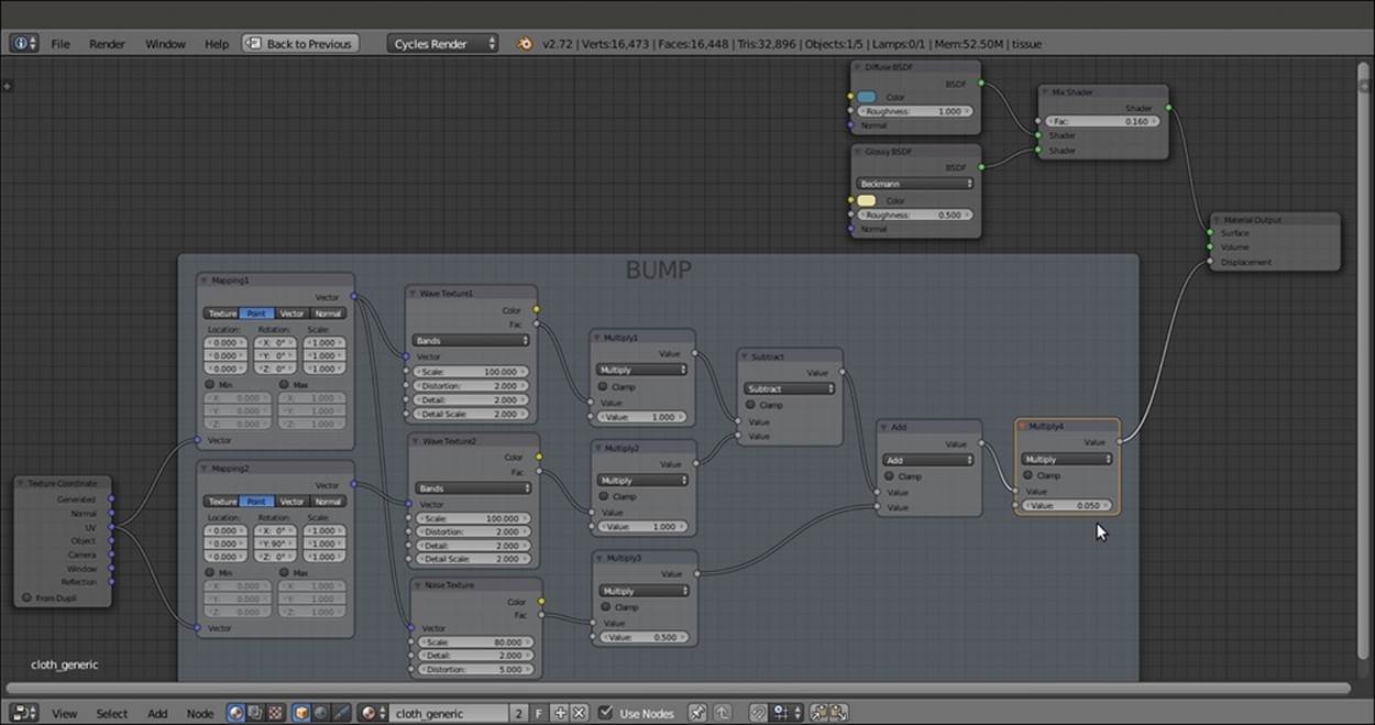
The shader and the network for the fabric bump pattern
13. Add two new Mapping nodes (press Shift + A and navigate to Vector | Mapping). Label them as Mapping3 and Mapping4. Then add two Wave Texture nodes (press Shift + A and navigate to Texture | Wave Texture). Label them as Wave Texture3 and Wave Texture4. As before, connect the UV output of the Texture Coordinate node to both the Mapping3 and Mapping4 nodes, and the output sockets of the latter to the new Wave Texture nodes.
14. Go to the Mapping3 node. Set the Rotation value of Z to -45° and the Scale value of Y to 2.000. In the Mapping4 node, set the Rotation value of Z to 45° and the Scale value of X to 2.000. Go to the two Wave Texture nodes to set the Scale value to 10.900and the Detail value to 0.000.
15. Add two ColorRamp nodes (press Shift + A and navigate to Converter | ColorRamp) and label them as ColorRamp1 and ColorRamp2. Connect the Fac output of the Wave Texture3 to the Fac input socket of the ColorRamp1 node, and the Fac output of theWave Texture4 node to the Fac input socket of the ColorRamp2 node.
16. Add a MixRGB node (press Shift + A and navigate to Color | MixRGB). Connect the Color output of the two ColorRamp nodes to the Color1 and Color2 input sockets of the MixRGB node. Set Blend Type to Multiply and the Fac value to 1.000.
17. Connect the Color output of the Multiply-MixRGB node to the Color input socket of the Diffuse BSDF shader node.
18. Add a Frame (press Shift + A and navigate to Layout | Frame). Press Shift and select the new nodes and then the Frame. Press Ctrl + P to parent them. Rename the Frame COLOR, as shown in the following screenshot:
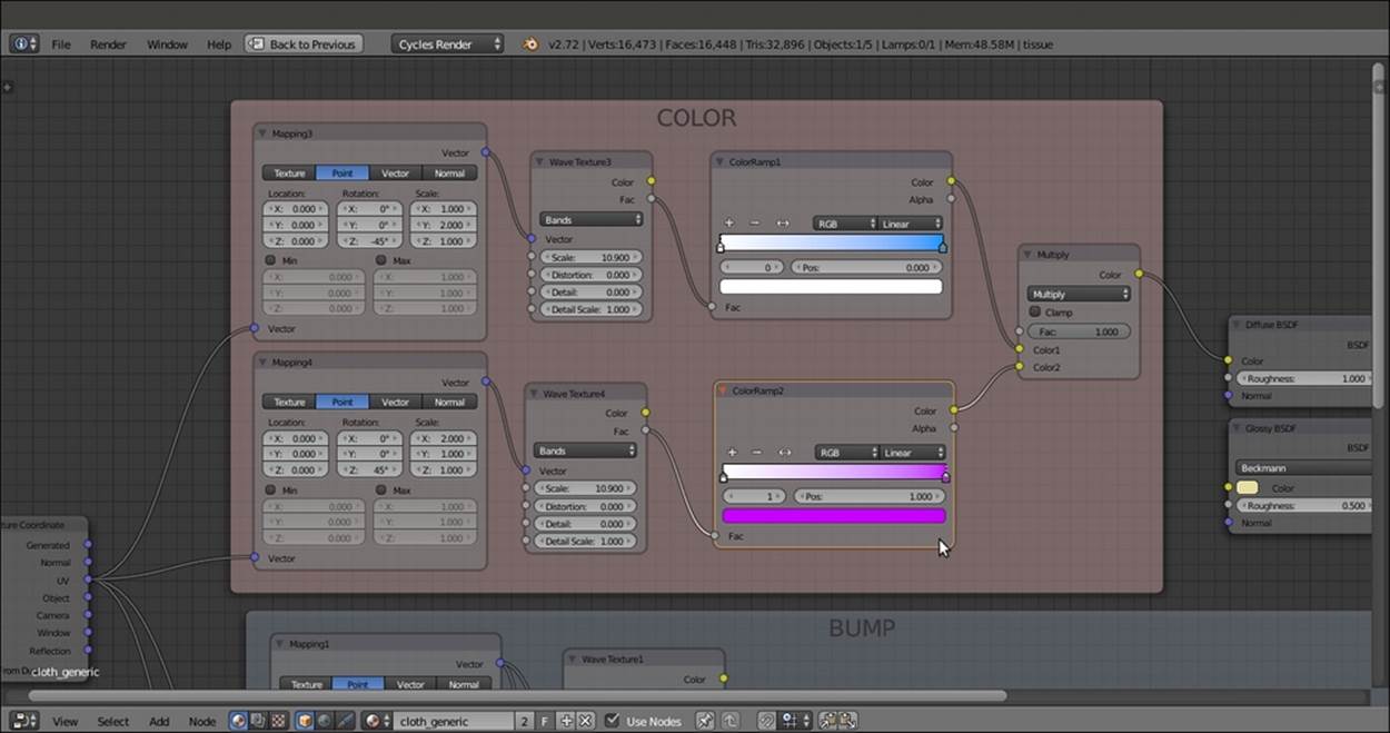
The COLOR frame
19. At this point, we can change the colors inside the two ColorRamp gradients to obtain colored patterns. In my example, I set the ColorRamp1 colors ranging from pure white going to a light blue, and violet for the ColorRamp2 node.
How it works...
· From steps 1 to 3, we just made the basic shader by mixing a rough Diffues BSDF shader (Roughness to 1.000) with a light glossy shader (the low Fac value of the Mix Shader node shows a lot more of the diffuse component than the glossy component)
· From steps 4 to 10, we built the bump texture of the fabric by mixing two Wave Texture nodes in different orientations and by adding a bit of noise
· From steps 11 to 18, we built a simple cross-color pattern
There's more...
A lot of variations can be obtained by setting different values for the bump and using different texture nodes and combinations for the color pattern, as shown in the following screenshot:
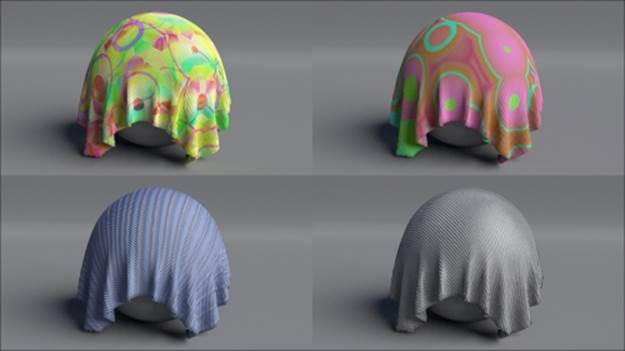
Different color patterns of the cloth material
Tip
All of these examples are included in the 9931OS_06_cloth.blend file provided with this book.
See also
To learn more about Blender cloth simulation, you can take a look at the online Blender documentation at http://wiki.blender.org/index.php/Doc:2.6/Manual/Physics/Cloth.
Creating a leather material with procedurals
In this recipe, we will create a leather-like material, as shown in the following screenshot:
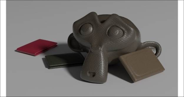
The leather-like material assigned to Suzanne and three wallet-like, simple objects
Start Blender and load the 9931OS_06_start.blend file, where there is already an unwrapped Suzanne mesh.
How to do it...
Now we are going to create the material by performing the following steps:
1. Click on New in the Material window under the main Properties panel or in the Node Editor toolbar. Rename the new material Leather_dark.
2. In the Material window, switch the Diffuse BSDF node with a Mix Shader node (label it as Mix Shader2). In its first Shader slot, select a Mix Shader node again (label it as Mix Shader1), and in the second slot, load an Anisotropic BSDF shader node.
3. Add a Fresnel node (press Shift + A and navigate to Input | Fresnel) and connect it to the Fac input sockets of both the Mix Shader nodes. Set the IOR value to 1.490.
4. Set the Anisotropic BSDF node's color to pure white and the Roughness value to 0.100. Add a Tangent node (press Shift + A and navigate to Input | Tangent). Connect it to the Tangent input socket of the Anisotropic BSDF shader, and in its Method to use for the Tangent slot, select the UV Map item. Optionally, click on the blank slot to the right to select the name of the UV layer to be used (this is useful if the mesh has two or more UV layers).
5. Add a Diffuse BSDF shader (press Shift + A and navigate to Shader | Diffuse BSDF) and a Glossy BSDF shader node (press Shift + A and navigate to Shader | Glossy BSDF). Connect the Diffuse BSDF node to the first Shader input socket of the Mix Shader1 node and the Glossy BSDF node to the second Shader input socket. Set the Diffuse BSDF node's Roughness value to 0.800. Set the Glossy BSDF distribution to Beckmann, Color to pure white, and its Roughness value to 0.300.
6. Add an RGB node (press Shift + A and navigate to Input | RGB) and connect its Color output to the Color input socket of the Diffuse BSDF node. Change the Color values of R to 0.100, G to 0.080, and B to 0.058, as shown in the following screenshot:
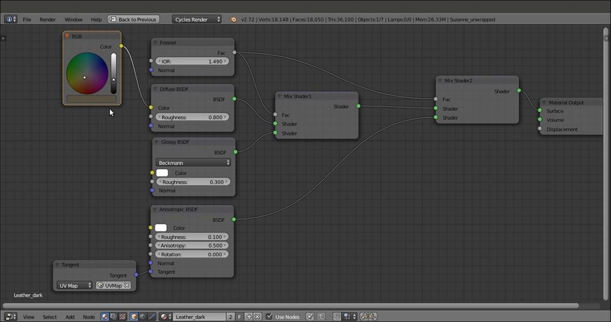
The shader part of the material
7. Add a Texture Coordinate node (press Shift + A and navigate to Input | Texture Coordinate) and two Mapping nodes (press Shift + A and navigate to Vector | Mapping). Connect the Object output of the Texture Coordinate node to the Vector input sockets of both the Mapping nodes (label them as Mapping1 and Mapping2). Then in the Mapping2 node, change the Rotation value of Y value to 90°.
8. Add two Voronoi Texture nodes (press Shift + A and navigate to Texture | Voronoi Texture) and two Wave Texture nodes (press Shift + A and navigate to Texture | Wave Texture). Place them in a column next to the Mapping nodes in this order from top to bottom: Voronoi Texture1, Wave Texture1, Voronoi Texture2, and Wave Texture2.
9. Set the Voronoi Texture1 node's Coloring to Cells and the Scale value to 60.000. Go to the Wave Texture1 node and set the Scale value to 10.000, the Distortion value to 10.000, Detail to 16.000, and Detail Scale to 0.300. Set the Scale value of the Voronoi Texture2 node to 10.000, and copy and paste the values from the Wave Texture1 node to the Wave Texture2 node.
10. Now connect the Mapping1 node output to the Vector input sockets of the two Voronoi Texture nodes and the Wave Texture1 node. Connect the output of the Mapping2 node to the Vector input socket of the Wave Texture2 node.
11. Add a MixRGB node (press Shift + A and navigate to Color | MixRGB). Set the Blend Type to Difference and the Fac value to 1.000. Connect the Color output of the Wave Texture1 node to the Color2 input socket of the Difference node, and the Coloroutput of the second Voronoi Texture2 node to its Color1 input socket.
12. Label the Difference node as Difference1. Then press Shift + D to duplicate it. Label the duplicate as Difference2 and connect the Color output of the Voronoi Texture2 node to its Color2 input socket. Connect the Color output of the Wave Texture2 node to the Color1 input socket of the Difference2 node.
13. Press Shift + D to duplicate the Difference node again, change its Blend Type to Multiply and label it as Multiply1. Connect the output of the Difference1 node to the Color1 input socket of the Multiply1 node. Then connect the output of the Difference2node to the Color2 input socket of the Multiply1 node.
14. Add a Math node (press Shift + A and navigate to Converter | Math), label it as Multiply3, and connect the output of the Multiply1 node to the first Value input socket. Set the second Value input socket to 0.100.
15. Press Shift + D to duplicate the Multiply3 node, label it as Multiply2, and connect the Color output of the Voronoi Texture1 node to the first Value input socket. Set the second Value input socket to -0.200.
16. Press Shift + D to duplicate the Multiply2 node, label it as Add, and change Operation to Add as well. Connect the output of the Multiply2 and Multiply3 nodes to the two Value input sockets.
17. Add two Bump nodes (press Shift + A and navigate to Vector | Bump). Label them as Bump1 and Bump2. Then connect the Bump1 to the Normal input sockets of both the Diffuse BSDF and Glossy BSDF shader nodes. Connect the Bump2 node to theNormal input of the Anisotropic BSDF shader. Set the Strength value of the Bump1 node to 0.500 and the Strength value of the Bump2 node to 0.250. Connect the output of the Add node to the Height input sockets of both the Bump nodes.
18. Add a ColorRamp node (press Shift + A and navigate to Converter | ColorRamp). Paste it between the first Difference1 node and the Multiply1 node. Set Interpolation to B-Spline and move the white color stop to the 0.255 position. Label it as ColorRamp1.
19. Press Shift + D to duplicate the ColorRamp1 node, label it as ColorRamp2, and paste it between the Difference2 node and the Multiply1 node, as shown in the following screenshot:
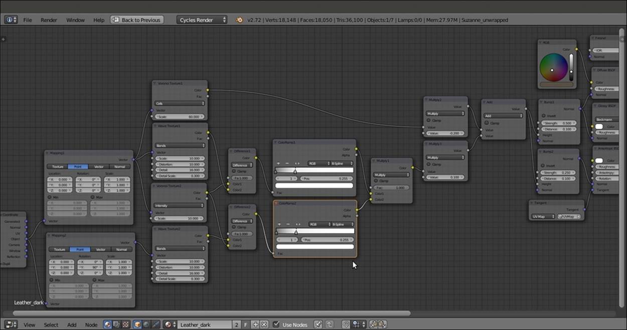
The completed network with the added bump pattern
How it works...
· From steps 1 to 6, we built the basic shader for the leather material.
· From steps 7 to 19, we built the bump pattern for the leather. We used two different Bump nodes with different values for the Diffuse BSDF and Glossy BSDF nodes and for the Anisotropic BSDF shader, to have slightly different light reflections on the surface.
Note
Note that we used the UV Map layer information of the mesh for the Tangent node to be connected to the Anisotropic BSDF shader, and the Object mapping node for the bump textures instead.
Actually, we could have used the UV mapping output for the texture nodes too, because the mesh had already been unwrapped. However, the scale values for all the nodes in that case would have been double and the flow of the textures on the polygons would have been different (based on the flow of the unwrapped faces in the UV window).
Creating a synthetic sponge material with procedurals
In this recipe, we will create a polyurethane sponge material (the type that you usually find in kitchens), as shown in the following screenshot:
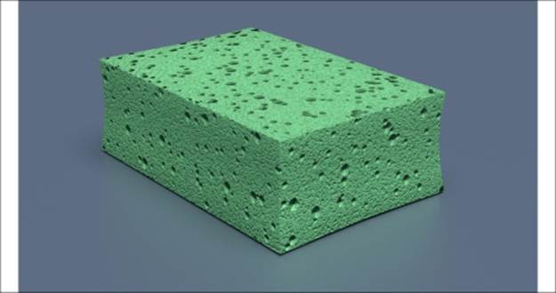
The synthetic sponge material when rendered
Getting ready
Follow these steps to create a synthetic sponge material with procedurals:
1. Start Blender and switch to the Cycles Render engine.
2. Select the default Cube, and in the Transform subpanel to the right of the 3D viewport (under Dimensions), change the values of X to 0.350, Y to 0.235, and Z to 0.116. Press Ctrl + A to apply the scale.
3. With the mouse arrow in the 3D viewport, add a Plane to the scene (press Shift + A and navigate to Mesh | Plane). Exit Edit Mode, and in the Transform subpanel (the Dimensions item), set the values of X to 20.000 and Y to 20.000. Press Ctrl + A to apply the scale. Move the Plane down (press G, then press Z, enter -0.05958, and then press Enter) to act as the floor for the sponge.
4. Select the Lamp item. In the Object data window, click on the Use Nodes button and change the type to Sun. Set the Size to 0.500, Color to pure white, and the Strength value to 5.000. In the Transform panel, set the values of Rotation value of X to 15°, Yto 0°, and Z to 76°.
5. Select the Camera item, and in the Object data window under the Lens subpanel, change the Focal Length value to 60.000. In the Transform subpanel, set the values of the Location value of X to 0.82385, Y to -0.64613, and Z to 0.39382. Change theRotation values of X to 68°, Y to 0°, and Z to 51°.
6. Go to the World window and click on the Use Nodes button under the Surface subpanel. Click on the little square with a dot on the right side of the color slot, and from the menu, select Sky Texture. Change Sky Type to Preetham and set the Strengthvalue to 0.100.
7. Go to the Render window, and under the Sampling subpanel, set the Clamp Direct and Clamp Indirect values to 1.00. Set Samples for Render and Preview to 50.
8. Split the 3D viewport into two rows. Convert the upper row to a Node Editor window. Split the bottom view into two parts and convert the left part to another 3D viewport. With the mouse arrow in the left 3D view, press 0 on the numeric keypad to go to theCamera view.
9. Select the Cube, and with the mouse arrow in the Camera view, press Shift + S. Navigate to Cursor to Selected to place the cursor on the pivot of the Cube (if it's elsewhere). Add Lattice to the scene (press Shift + A and select Lattice). Press Tab to exitEdit Mode. In the Transform subpanel, under Scale, set the values of X to 0.396, Y to 0.264, and Z to 0.129. Go to the Object data window, and in the Lattice subpanel set the U, V, and W values to 3.
10. Reselect the Cube and go to the Object modifiers window. Assign a Subdivision Surface modifier, switch the type of subdivision algorithm from Catmull-Clark to Simple, and set the Subdivisions value to 2 for both View and Render.
11. Assign a Bevel modifier and set the Width value to 0.0010. Assign a Lattice modifier, and in the empty Object field, select the Lattice name. Reselect the Lattice object and press Tab to enter Edit Mode. Select the Lattice vertices that are indicated in the following screenshot:
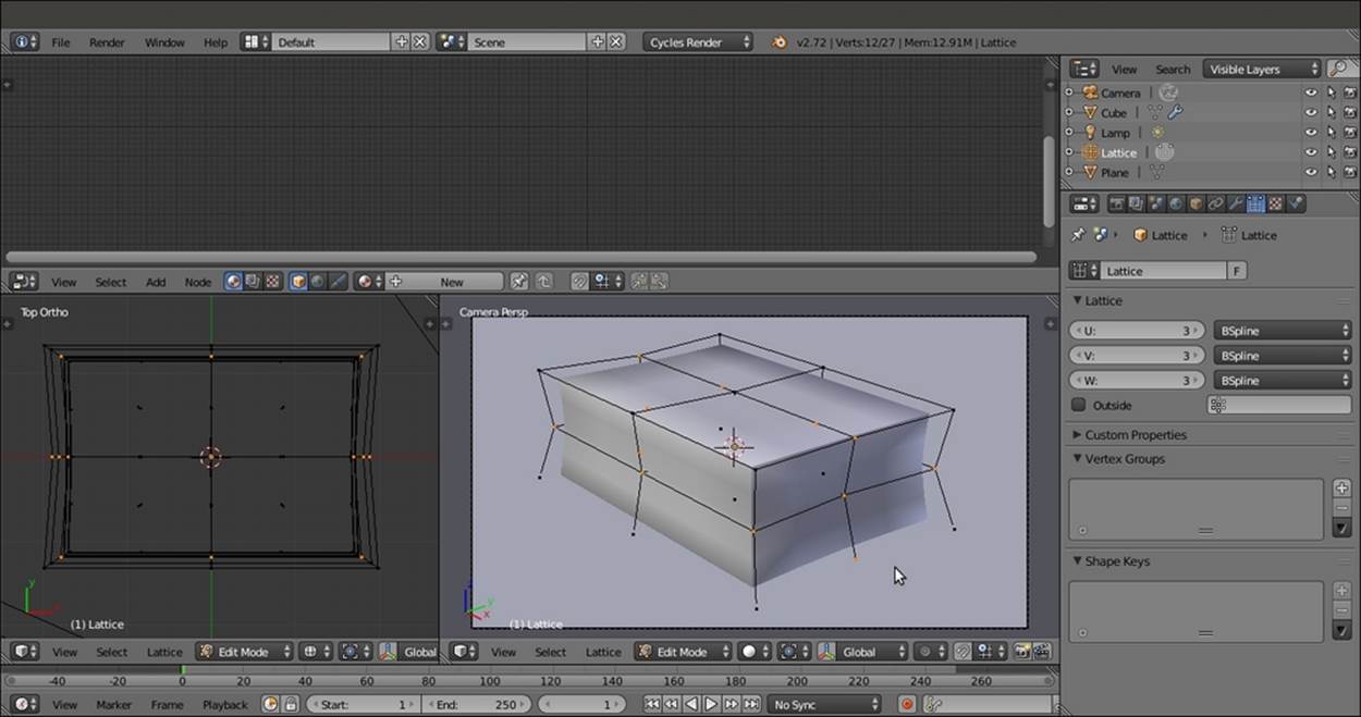
The setup for the sponge scene in Solid viewport shading mode
12. Scale the selected vertices on the x and y axes to slightly smaller values (press S, then press Shift + Z, enter digit .9, and press Enter). Then scale only the upper vertices to slightly smaller values, and similarly scale other vertices to obtain a shape similar to a kitchen sponge. Then exit Edit Mode (press Tab).
13. Reselect the Cube, navigate to Tool Shelf | Tools | Shading, and select Smooth. With the mouse arrow in the 3D view, press N and T to close the Transform and Tool Shelf panels. Go to the Material window.
How to do it...
Now let's create the material by performing the following steps:
1. First, select the Plane and click on New in the Material window under the main Properties panel or in the Node Editor toolbar. In the Material window, switch the Diffuse BSDF node with a Mix Shader node. In the first Shader slot, select a Diffuse BSDFnode, and in the second Shader slot, select a Glossy BSDF shader node. Set Distribution of the Glossy BSDF shader to Beckmann, the Fac value of the Mix Shader to 0.400, and the Diffuse BSDF node's Color to a shade of blue (in my case, R to 0.110,G to 0.147, and B to 0.209).
2. Now select the Cube object and click on Use Nodes in the Material window under the main Properties panel or in the Node Editor window's toolbar. Rename the new material sponge_polyurethane.
3. In the Material window, switch the Diffuse BSDF node with a Mix Shader node. In the Label slot in the Node subpanel under the Properties panel of the Node Editor window (if this is not present, press the N key to make it appear), label it as Mix Shader1. Go to the Material window, and in the Mix Shader1 node's first Shader slot, select a Mix Shader node again. Label it as Mix Shader2. In the second Shader slot, select an Add Shader node.
4. In the first Shader slot of the Mix Shader2 node, select a Diffuse BSDF shader node, and in the second slot, a Velvet BSDF node. Set the Diffuse BSDF node's Roughness value to 1.000 and the Velvet node's Sigma value to 0.600.
5. Connect the output of the Velvet shader to the first Shader input of the Add Shader node. In its second Shader input, load a Glossy BSDF shader and set the Roughness value to 0.350.
6. Add a Fresnel node (press Shift + A and navigate to Input | Fresnel) and connect it to the Fac input socket of the Mix Shader1 node. Set the IOR value to 1.496. Add an RGB node (press Shift + A and navigate to Input | RGB) and connect its output to theColor input sockets of the Diffuse BSDF, Velvet, and Glossy BSDF shader nodes. Set the RGB node's Color of R to 0.319, G to 1.000, and B to 0.435 (any other color is also fine), as shown in the following screenshot:
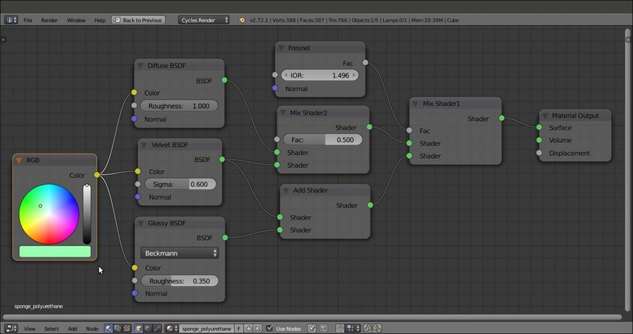
The basic shader component
7. Add a Texture Coordinate node (press Shift + A and navigate to Input | Texture Coordinate), a Mapping node (press Shift + A and navigate to Vector | Mapping), two Voronoi Texture nodes (press Shift + A and navigate to Texture | Voronoi Texture), and two Noise Texture nodes (press Shift + A and navigate to Texture | Noise Texture). Label the textures as Voronoi Texture1, Voronoi Texture2, Noise Texture1, and Noise Texture2.
8. Place the four textures in a row. Then connect the Object output of the Texture Coordinate node to the Vector input socket of the Mapping node, and the Vector output of this node to the Vector input sockets of the four texture nodes.
9. Set the Scale value of the Voronoi Texture1 node to 38.000, the Voronoi Texture2 node to 62.300, the Noise Texture1 node to 300.000, and the Noise Texture2 node to 900.000.
10. Add three ColorRamp nodes (press Shift + A and navigate to Converter | ColorRamp). Label them as ColorRamp1, ColorRamp2, and ColorRamp3. Connect the Color output of the Voronoi Texture1 node to the Fac input socket of the ColorRamp1 node, theColor output of the Voronoi Texture2 node to the Fac input socket of the ColorRamp2 node, and the Color output of the Noise Texture1 node to the Fac input socket of the ColorRamp3 node.
11. Add four Math nodes (press Shift + A and navigate to Converter | Math). Set Operation to Multiply and label them as Multiply1, Multiply2, Multiply3, and Multiply4. Connect the Color output of the three ColorRamp nodes to the first Value input socket of the first three Multiply-Math nodes, and the Color output of the Noise Texture2 node to the first Value input socket of the Multiply4 node. Set the second Value input socket of the Multiply1 and Multiply2 nodes to 1.000, the second Value input socket of theMultiply3 node to 0.100, and the second Value input socket of the Multiply4 node to 0.050.
12. Add a MixRGB node (press Shift + A and navigate to Color | MixRGB). Connect the output of the Multiply1 node to the Color1 input socket and the output of the Multiply2 node to the Color2 input socket. Change Blend Type to Add and the Fac value to1.000. Label the Add-MixRGB node as Add1.
13. Press Shift + D to duplicate the Add1 node, and label it as Add2. Connect the output of the Add1 node to the Color1 input socket. Then connect the output of the Multiply3 node to the Color2 input socket of the Add2 node.
14. Press Shift + D to duplicate the Add2 node, and label it as Add3. Paste it between the Multiply3 and Add2 nodes, and connect the output of the Multiply4 node to the Color2 input socket of the Add3 node.
15. Add a new Math node (press Shift + A and navigate to Converter | Math), set Operation to Multiply, and label it as Multiply5. Connect the output of the Add2 node to the first Value input socket of the Multiply5 node, and set the second Value input socket to 1.000.
16. Connect the output of the Multiply5 node to the Displacement input socket of the Material Output node, as shown in the following screenshot:
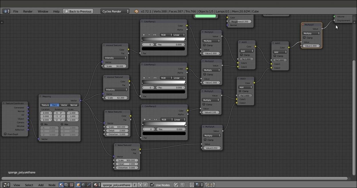
The bump pattern
17. Now box-select (press the B key and then click and drag the selection to enclose the objects) the ColorRamp1, ColorRamp2, Multiply1, Multiply2, Add1, Add2, and Multiply5 nodes. Press G and move them to the right to make room for new nodes on the left side.
18. Add an RGB Curves node (press Shift + A and navigate to Color | RGB Curves) and paste it between the Voronoi Texture1 node and the ColorRamp1 node. Label it as RGB Curves1. Click on the curve to add a control point, and in the coordinate slots below the node window, set the X value to 0.26111 and the Y value to 0.50000. Click to add a second control point. Set X to 0.73889 and Y to 0.51111.
19. Press Shift + D to duplicate the RGB Curves1 node. Paste it between the Voronoi Texture2 and ColorRamp2 nodes. Label it as RGB Curves2.
20. Go to the ColorRamp1 node and move the white color stop to the 0.240 position. Then go to the ColorRamp2 node and repeat this step. Next, go to the ColorRamp3 node, move the white color stop to the 0.550 position, and set Interpolation to Ease, as shown in the following screenshot:
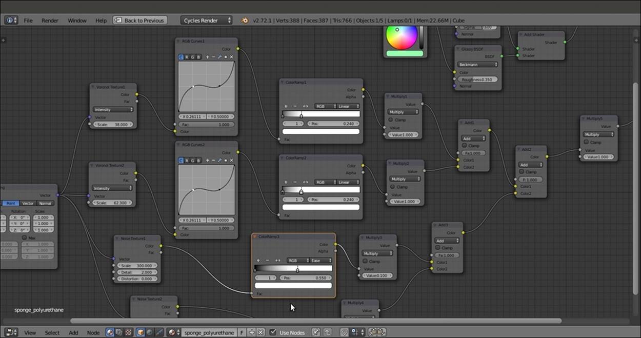
Tweaking the bump pattern
How it works...
· From steps 2 to 6, we built the basic shader for the sponge material and the color. As you can see in the Rendered camera view, without the bump pattern, there is a visible artifact in the more distant side of the mesh. This is due to the Smooth shading we set in step 13 of the Getting ready section. Setting the shading to Flat again would remove the artifact, but would also show the blocky faces of the deformed sponge mesh. In this case, because of the bump pattern and the fact that the mesh is subdivided, this is not a major issue, and both solutions (smooth but with artifacts or flat but blocky) are fine.
· From steps 7 to 20, we built the sponge bump pattern by mixing Voronoi Texture nodes at different sizes, with increased contrast due to the ColorRamp nodes. Then we add some noise to avoid a highly smoothed surface.
Creating a spaceship hull shader
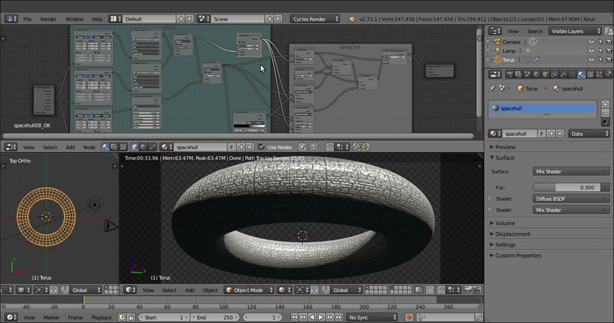
In this recipe, we will create a spaceship hull material. We will add random, tiny light windows based on the values of procedural textures, and the spaceship's logo as if it were painted in red on the hull, as shown in the following screenshot:
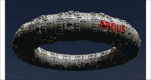
The final, rendered spaceship hull material assigned to a displaced Torus primitive
Getting ready
To start creating this spaceship hull, we need the spaceship and space first. Follow these steps to build a quick and easy model and set up the scene:
1. Start Blender and switch to the Cycles Render engine. Select the default Cube and delete it.
2. With the mouse arrow in the 3D view, press Shift + A and add a Torus primitive (press Shift + A and navigate to Mesh | Torus). In Edit Mode, scale it to at least twice its current size (press A to select all the vertices, then type S, enter 2, and press Enter).
3. Exit Edit Mode, and in Outliner, select the Lamp object. In the Object data window, change it to Sun. Then set the Size value to 0.050. Click on the Use Nodes button and set the Strength value to 10.000. Change the Color value of RGB to 0.800.
4. Go to the World window and click on the Use Nodes button under the Surface subpanel. Click on the little square with a dot to the right of the Color slot. From the menu, select Sky Texture. Set the Strength to 0.100.
5. Select the Camera, and in the Transform panel, set the Location values of X to 6.10677, Y to -0.91141, and Z to -2.16840. Set the Rotation values of X to 112.778°, Y to -0.003°, and Z to 81.888°.
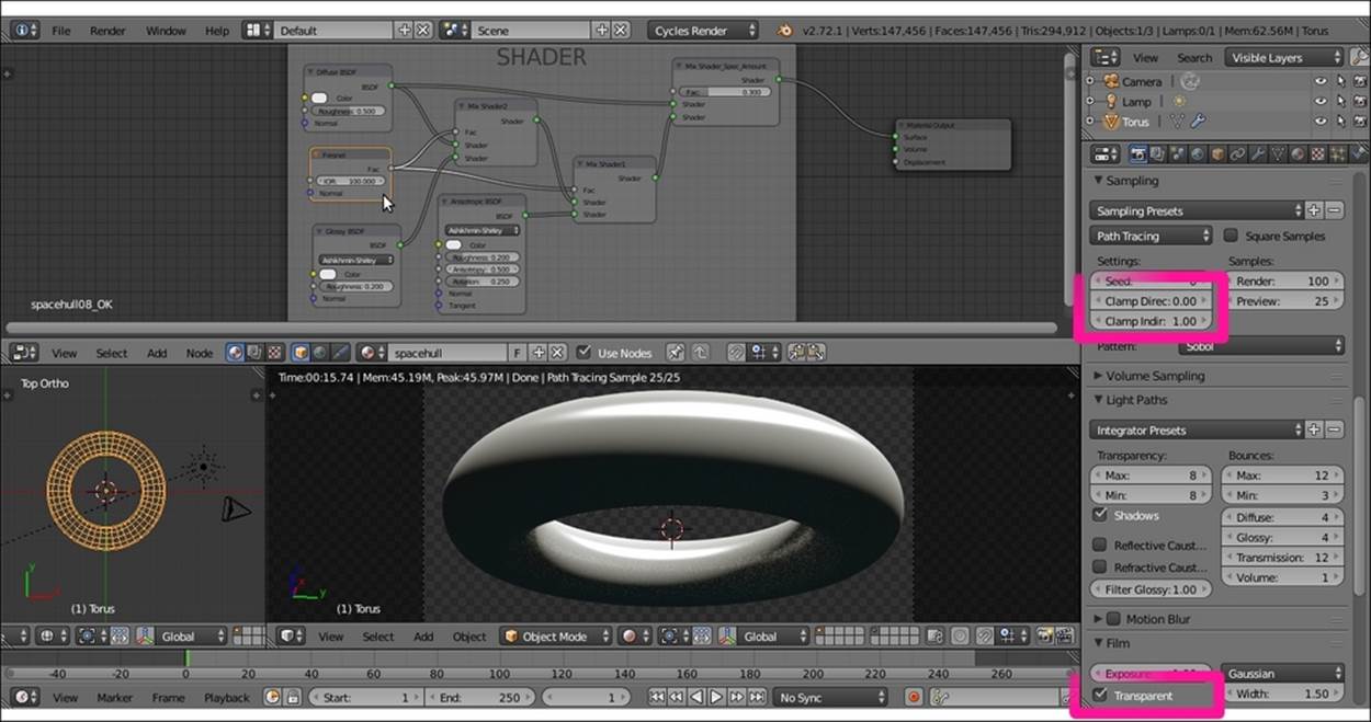
6. Go to the Render window, and under the Sampling subpanel, set the Samples to 25 for Preview and 100 for Render. Then set the Clamp Indirect value to 1.00, but let the Clamp Direct value remain as 0.00. Go to the Film subpanel and check theTransparent item. Then set the output File Format to RGBA.
7. Under the Light Paths subpanel, disable both the Reflective and Refractive Caustics items. Set Filter Glossy value to 1.00. Under the Performance subpanel, set the Viewport BVH Type to Static BVH (this should speed up the rendering a bit, considering the fact that the model is static and doesn't change shape). Check the Persistent Images and Use Spatial Splits items.
8. Press N with the mouse arrow in the 3D view to close the Properties panel. Then press T to get rid of the Tool Shelf panel. Split the 3D view into two rows. Convert the upper row to a Node Editor window.
9. Split the bottom window into two parts. Convert the left part to a UV/Image Editor window. Select Torus and press Tab to go to Edit Mode. In the window toolbar, change the selection mode to Face select. Select only one face on the mesh (whichever you prefer). Press the A key twice to select all the faces, and keep the first face selected as the active face. Then press the U key. In the UV Mapping pop-up menu, select the Follow Active Quads item, and then in the next pop-up menu set Even as Edge Length Mode. Click on the OK button.
10. With the mouse arrow in the UV/Image Editor window, press A to select all the vertices of the UV islands. Then scale them to one-third of their current size (press S, enter digit .3, and press Enter). Press Tab to exit Edit Mode, and change UV/Image Editorto 3D View. Convert the right 3D viewport to a Camera view by pressing the 0 key on the numeric keypad (with the mouse arrow in the 3D view).
11. Go to the Object modifiers window and assign a Subdivision Surface modifier to Torus. Set the Subdivisions level to 4 for both View and Render. Set the Camera view mode to Rendered and go to the Material window.
How to do it...
Now let's start creating the material. The steps to create a basic hull shader are as follows:
1. Click on New in the Material window under the main Properties panel or in the Node Editor toolbar. Rename the new material spacehull.
2. In the Material window, switch the Diffuse BSDF node with a Mix Shader node. Label it as Mix Shader1. In the first Shader slot, select a new Mix Shader node (label it as Mix Shader2), and in the second slot, select an Anisotropic BSDF node.
3. In the first Shader slot of the Mix Shader2 node, select a Diffuse BSDF node, and in the second slot, select a Glossy BSDF node. Set the Distribution of both the Glossy BSDF and Anisotropic BSDF nodes to Ashikmin-Shirley.
4. In the Anisotropic BSDF shader node, set the Rotation value to 0.250. In the Diffuse BSDF node, set the Roughness value to 0.500.
5. Add a new Mix Shader node (press Shift + A and navigate to Shader | Mix Shader) and paste it between the Mix Shader1 and the Material Output nodes. Label it as Mix Shader_Spec_Amount and connect the output of the Diffuse BSDF node to the first Shaderinput socket (so that the link from the Mix Shader2 node automatically switches to the second socket). Set the Fac value to 0.300.
6. Add a Fresnel node (press Shift + A and navigate to Input | Fresnel). Connect its output to the Fac input sockets of the Mix Shader1 and Mix Shader2 nodes. Set the IOR value to 100.000.
7. Add a Frame (press Shift + A and navigate to Layout | Frame). Press Shift and select all the nodes except the Material Output node. Then select the Frame and press Ctrl + P to parent all of them. Label the frame as SHADER, as shown in the following screenshot:
The SHADER frame
The steps to create hull's panels are as follows:
8. Add a Texture Coordinate node (press Shift + A and navigate to Input | Texture Coordinate), a Mapping node (press Shift + A and navigate to Vector | Mapping), two Image Texture nodes (press Shift + A and navigate to Texture | Image Texture), and one Musgrave Texture node (press Shift + A and navigate to Texture | Musgrave Texture).
9. Label the textures as Image Texture1_Hull, Image Texture2_Hull, and Musgrave Texture_Hull. Place them in a column.
10. Press Shift + D to duplicate the Mapping node twice. Label the nodes as Mapping1_Hull, Mapping2_Hull, and Mapping3_Hull. Place them in a column to the left of the texture nodes. Connect the UV output of the Texture Coordinate node to the Vector input sockets of the three Mapping nodes. Connect the Vector output of each of the Mapping nodes to the Vector input socket of each of the texture nodes.
11. Click on the Open button in the Image Texture1_Hull node to load image spacehull.png. Then click on the little arrows to the left of the Open button in the Image Texture2_Hull node to select the same image texture. Go to the Musgrave Texture node and set the Scale value to 115.500, the Detail value to 4.500, the Dimension value to 0.200, and the Lacunarity value to 0.600.
12. Go to the Mapping1_Hull node and set the Scale value of X to 2.000, Y to 4.000, and Z to 6.000. Then go to the Mapping2_Hull node and set the Scale value of Y to 2.000 and Z to 3.000. Next, go to the Mapping3_Hull node and set the Scale value of Z to0.100.
13. Add a MixRGB node (press Shift + A and navigate to Color | MixRGB). Set Blend Type to Multiply and the Fac value to 1.000. Label it as Multiply1_Hull. Then connect the Color output of the Image Texture1_Hull node to the Color1 input socket and theColor output of the Image Texture2_Hull node to the Color2 input socket.
14. Press Shift + D to duplicate the Multiply1_Hull node, change Blend Type to Overlay, and label it as Overlay_Hull. Set the Fac value to 0.050. Connect the output of the Multiply1_Hull node to the Color1 input socket and the Color output of the Musgrave Texture node to the Color2 input socket.
15. Add a ColorRamp node (press Shift + A and navigate to Converter | ColorRamp), label it as ColorRamp_Hull, and connect the output of the Overlay_Hull node to its Fac input socket. Move the black color stop to the 0.500 position.
16. Add a Bump node (press Shift + A and navigate to Vector | Bump), label it as Bump_Hull, and connect the output of the Multiply1_Hull node to the Height input socket. Set the Strength value to 0.400.
17. Add a Frame (press Shift + A and navigate to Layout | Frame). Press Shift and select the three Mapping nodes, the two Image Texture nodes, the Musgrave Texture node, the Bump node, the ColorRamp node, the two MixRGB nodes, and then theFrame. Press Ctrl + P to parent them. Label the frame as HULL, as shown in the following screenshot:
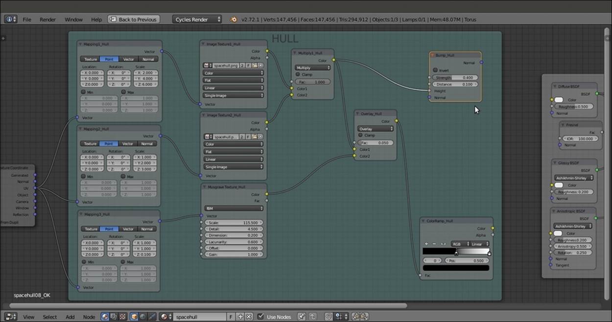
The HULL frame
18. Connect the Normal output of the Bump_Hull node to the Normal input sockets of the Diffuse BSDF, Glossy BSDF, and Anisotropic BSDF nodes inside the SHADER frame. Then connect the output of the Overlay_Hull node to the Color input sockets of the same Diffuse BSDF, Glossy BSDF, and Anisotropic BSDF nodes. Next, connect the Color output of the ColorRamp_Hull node to the Roughness input sockets of the Glossy BSDF and Anisotropic BSDF shader nodes, as shown in this screenshot:
The output of the HULL frame connected to the SHADER frame nodes
The steps to create hull's logo are as follows:
19. Add a new Mapping node (press Shift + A and navigate to Vector | Mapping) and a new Image Texture node (press Shift + A and navigate to Texture | Image Texture). Label them as Mapping4_Name and Image Texture3_Name, respectively. Connect the UV output of the Texture Coordinate node to the Mapping4_Name node, and the output of this node to the Vector input socket of the Image Texture_Name node.
20. Click on the Open button of the Image Texture node and load the spacehull_name.png image, an image texture of the ARGUS logo with a transparent background (alpha channel).
21. Go to the HULL frame and add a MixRGB node (press Shift + A and navigate to Color | MixRGB). Label it as Mix_Hull_Name and paste it between the Overlay_Hull node and the Diffuse BSDF shader node. Then connect its Color output to the Color input socket of the Glossy BSDF and Anisotropic BSDF shader nodes.
22. Connect the Color output of the Image Texture_Name node to the Color2 input socket of the Mix_Hull_Name node. Then connect the Alpha output of the Image Texture_Name node to the Fac input socket of the Mix_Hull_Name node.
23. Go to the Mapping4_Name node and check both the Min and Max items. Then set the Location value of X to -3.300 and Y to 1.000. Set the Scale value of Y to 2.500. (These values depend on the scale and location you want for your logo on the spaceship; just experiment looking at the real-time-rendered preview.)
24. Add a Frame (press Shift + A and navigate to Layout | Frame). Press Shift and select the Mapping4_Name node, the Image Texture3_Name node, and then the Frame. Press Ctrl + P to parent them. Label the frame as NAME, as shown in the following screenshot:
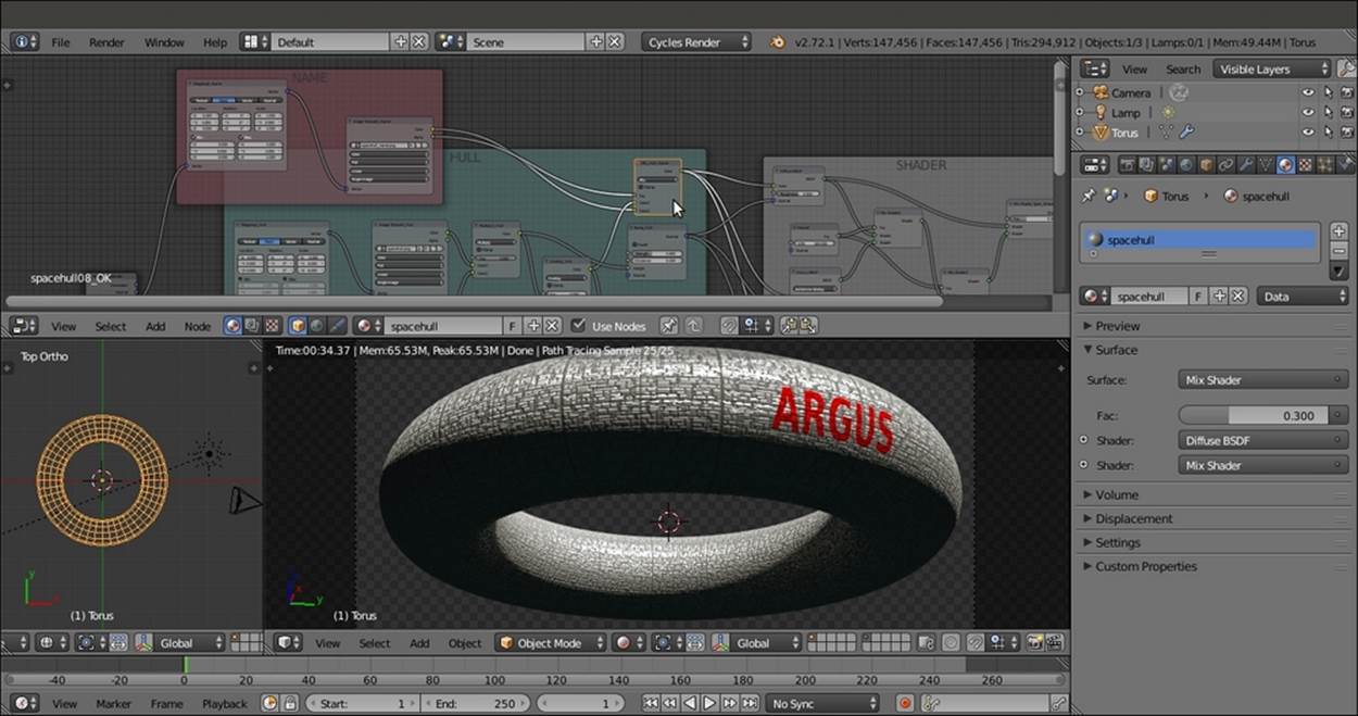
The ARGUS logo on the hull
The steps to create the windows are as follows:
25. Add a new Mapping node (press Shift + A and navigate to Vector | Mapping) and two Image Texture nodes (press Shift + A and navigate to Texture | Image Texture). Label them as Mapping5_Windows, Image Texture4_Windows, and Image Texture5_Windows. Connect the Texture Coordinate node's UV output and the Mapping node's output to the Image Texture nodes as usual. Then set the Mapping node's Scale values to 10.000 for the three axes.
26. Click on the Open button of the Image Texture4_Windows node and load the spacehull_windows_lights.png image. Then click on the Open button of the Image Texture5_Windows node and load the spacehull_windows_bump.png image. Set Color Space for both the image nodes to Non-Color Data.
27. Add two MixRGB nodes (press Shift + A and navigate to Color | MixRGB). Set Blend Type to Multiply and Fac values to 1.000. for both the nodes Label them as Multiply2_Windows_Light and Multiply2_Windows_Bump. Connect the output of the Image Texture4_Windows node to the Color1 input socket of the Multiply2_Windows_Light node, and the output of the Image Texture5_Windows node to the Color1 input socket of the Multiply2_Windows_Bump node.
28. Add a ColorRamp node (press Shift + A and navigate to Converter | ColorRamp), label it as ColorRamp_Windows, and move the black color stop to the 0.919 position. Connect the output of the Multiply2_Windows_Light node to its Fac input socket.
29. Add a new Bump node (press Shift + A and navigate to Vector | Bump), label it as Bump_Windows, and connect the output of the Multiply2_Windows_Bump node to the Height input socket. Set the Strength value to 50.000.
30. Add a Frame (press Shift + A and navigate to Layout | Frame). Press Shift and select the Mapping5_Windows node, the Image Texture4_Windows and Image Texture5_Windows nodes, the two MixRGB nodes, the ColorRamp_Windows and theBump_Windows nodes, and then the Frame. Press Ctrl + P to parent them. Label the frame as WINDOWS, as shown in the following screenshot:
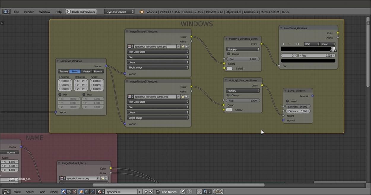
The WINDOWS frame
31. Add a Vector Math node (press Shift + A and navigate to Converter | Vector Math) and set Operation to Average. Connect the Normal output of the Bump_Windows node inside the WINDOWS frame to the first Vector input socket, and the Normal output of the Bump_Hull node inside the HULL frame to the second Vector input socket. Then connect the Normal output of the Average Bump_Hull node to the Normal input sockets of the Diffuse BSDF, Glossy BSDF, and Anisotropic BSDF shader nodes, as shown in this screenshot:
The windows bump visible on the hull
The steps to create the location mask for the windows are as follows:
32. Add one more Mapping node (press Shift + A and navigate to Vector | Mapping) and four Checker Texture nodes (press Shift + A and navigate to Texture | Checker Texture). Connect the Texture Coordinate node and the nodes as usual. Then label them as Mapping6_Mask, Checker Texture1_Mask, Checker Texture2_Mask, Checker Texture3_Mask, and Checker Texture4_Mask. In all, the four Checker Texture nodes change Color2 to pure black.
33. Add a MixRGB node (press Shift + A and navigate to Color | MixRGB), set Blend Type to Screen and Fac value to 1.000, and label it as Screen_Mask. Connect the Color output of the Checker Texture1_Mask node to the Color1 input socket of theScreen_Mask node, and the Color output of the Checker Texture2_Mask node to the Color2 input socket.
34. Press Shift + D to duplicate the MixRGB node, change the duplicate node's Blend Type to Add, and label it as Add_Mask1. Connect the output of the Screen_Mask node to the Color1 input socket. Then connect the Color output of the Checker Texture3_Mask node to the Color2 input socket.
35. Press Shift + D to duplicate the Add_Mask1 node, and label the duplicate as Add_Mask2. Connect the output of the Add_Mask1 node to the Color1 input socket. Then connect the Color output of the Checker Texture4_Mask node to the Color2 input socket.
36. Add a ColorRamp node and label it as ColorRamp_Mask. Connect the output of the Add_Mask2 node to its Fac input socket. Then move the black color stop to the 0.100 position and the white color stop to the 0.000 position. Set Alpha of the black color stop to0.000.
37. Go to the Checker Texture nodes. Set the Scale value for the Checker Texture1_Mask node to 1.600, the Checker Texture2_Mask node to 8.800, the Checker Texture3_Mask node to 3.000, and the Checker Texture4_Mask node to 9.700. Go to theMapping6_Mask node and set the Scale values to 0.500 for all the three axes.
38. Add a Frame (press Shift + A and navigate to Layout | Frame). Press Shift to select the recently added nodes and then the Frame. Press Ctrl + P to parent them. Rename the frame as MASK WINDOWS as shown in the following screenshot:
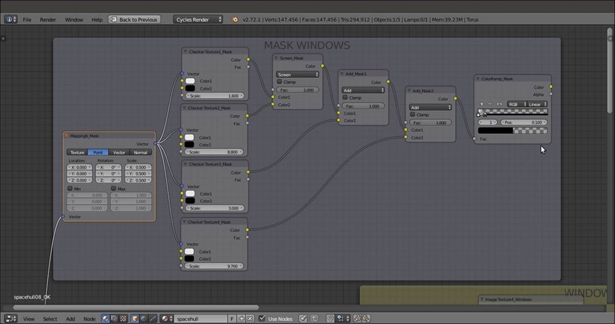
The MASK WINDOWS frame
The steps to create the final connections are as follows:
39. Connect the Color output of the ColorRamp_Mask node to the Color2 input sockets of both the Multiply2_Windows_Lights and Multiply2_Windows_Bump nodes, as shown in this screenshot:
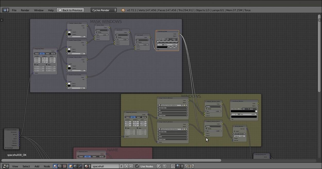
The MASK WINDOWS frame output connected to the WINDOWS frame nodes
40. Go to the SHADER frame and add a Mix Shader node (press Shift + A and navigate to Shader | Mix Shader). Label it as Mix Shader3 and paste it between the Mix Shader_Spec_Amount and the Material Output nodes.
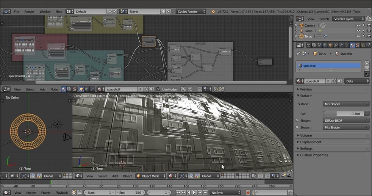
41. Connect the Color output of the ColorRamp_Windows node inside the WINDOWS frame to the Fac input socket of the Mix Shader3 node, as shown in the following screenshot:

The output of the WINDOWS frame connected to the SHADER frames nodes and the result in the Rendered preview
The steps to create the light emitter for the windows are as follows:
42. Inside the SHADER frame, add an Emission shader node (press Shift + A and navigate to Shader | Emission), a ColorRamp node (press Shift + A and navigate to Converter | ColorRamp), and an Object Info node (press Shift + A and navigate to Input |Object Info). Label the ColorRamp node as ColorRamp_Lights_Colors, change Interpolation to Constant, and add six more color stops (eight total). Change the color values alternatively of R to 0.800, G to 0.517, B to 0.122; and R to 0.800, G to 0.198, and B to0.040 (or any other color you prefer).
43. Connect the Random output of the Object Info node to the Fac input socket of the ColorRamp node, and the output of this node to the Color input socket of the Emission node.
44. Connect the Emission node's output to the second Shader input socket of the Mix Shader3 node. Then set Strength to 3.000, as shown in the following screenshot:
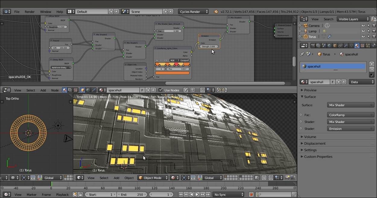
The windows on the hull getting illuminated by the ColorRamp_Lights_Colors node and an Emission node output connected to the SHADER output
How it works...
· From step 1 to step 7, we built the general shader for the metallic hull, which is similar to the metal node group we saw in Chapter 4, Creating Man-made Materials in Cycles. This was achieved by mixing Diffuse BSDF and Glossy BSDF shaders with anAnisotropic BSDF node on a ground with a quite high IOR value (100.000), and through the usual Mix Shader nodes. We added one more Mix Shader node (Mix Shader_Spec_Amount) to include the possibility of setting more specularity than anisotropy, and vice versa.
· From step 8 to step 18, we built the HULL frame group by superimposing two differently scaled versions of the same image. Then they could be used for the color, bump, and specular components. These components were obtained by contrasting the paneling through a ColorRamp node and then going straight to the Glossy BSDF shader's roughness and the Anisotropic BSDF shader, to add a metallic look. The mixture of both Glossy BSDF and Anisotropic BSDF is made on the ground of a Fresnelnode set to 100.000. A very high value like this is needed because the specularity is then mixed again with the Diffuse BSDF component to the purpose to obtain a slider to tweak the effect.
· From step 19 to step 24, we added the red hull's logo, ARGUS, using its own alpha channel to overimpose it on the hull surface's panels..
· From step 25 to step 30, we built the WINDOWS frame group.
· In step 31, we merged (averaged) the bump effect of the windows with the bump effect of the hull's panels.
· From step 32 to step 38, we made the masking for the windows to give them a random appearance.
· From step 39 to step 41, we simply connected the various frames' output.
· From step 42 to step 44, we created the light-emitting material for the windows. Note that the WINDOWS_ MASK frame group provides the masking for the windows' positions. The WINDOW frame group provides the whiteness values for the windows, the bump, and the last nodes added to the SHADER frame the light emission based on the output of the previous frame groups.
There's more...
The appearance of the hull can be improved even further using some displacement to add geometric details to the spaceship surface, which (at the moment) is a bit too smooth:
1. Go to the Object modifiers window and assign a second Subdivision Surface modifier to Torus. Set the Subdivisions levels to 2 for both View and Render.
2. Assign a Displace modifier. Then click on the Show texture in texture tab button on the right side of the Texture slot. In the Textures window, click on the New button. Then replace the default Clouds texture with an Image or Movie texture.
3. Click on the Open button and load the spacehull_displ.exr texture.
4. Go back to the Object modifiers window and set the displacement's Strength value to 0.200. In the Texture Coordinates slot, select UV.
This way, the displacement features get mixed with the hull bump panels of the shader, giving a nice result. The spacehull_displ.exr texture is a 32-bit float displacement map created and stored in the Blender Internal engine. I modeled the Planes and scaled Cubes a simple greeble panel, then I baked the displacement on a different and unwrapped Plane, as shown in the following screenshot:
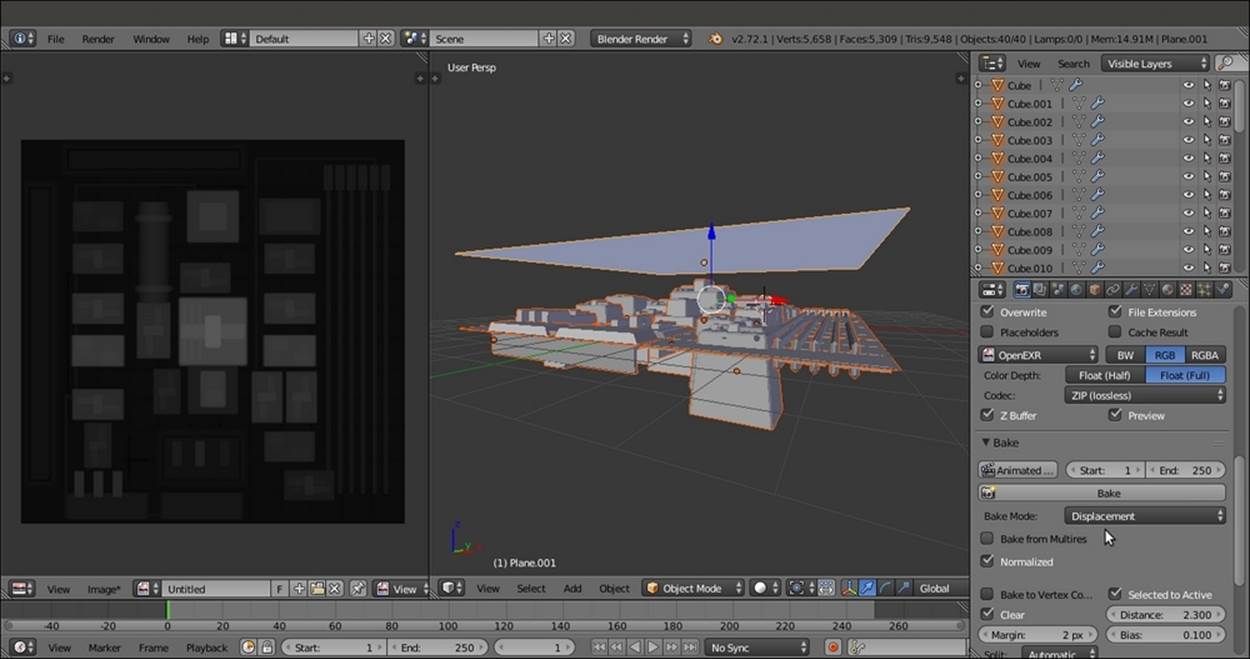
The greeble scene ready for the baking
Tip
If you want to take a look at the baking scene, open the 9931OS_06_greeble.blend file.
Finally, we can try to set the first Subdivision Surface modifier level to 4 and lower the second Subdivision Surface modifier's level to 1. Then, starting from the top one, apply all the modifiers. You will inevitably lose the details but will obtain a much lighter mesh—589,824 faces against the initial 2,359,296—and considering the fact that most of the details come from the texturing, the result looks pretty good (at least from a distance). It also looks good if the shading is set to Flat instead of Smooth.
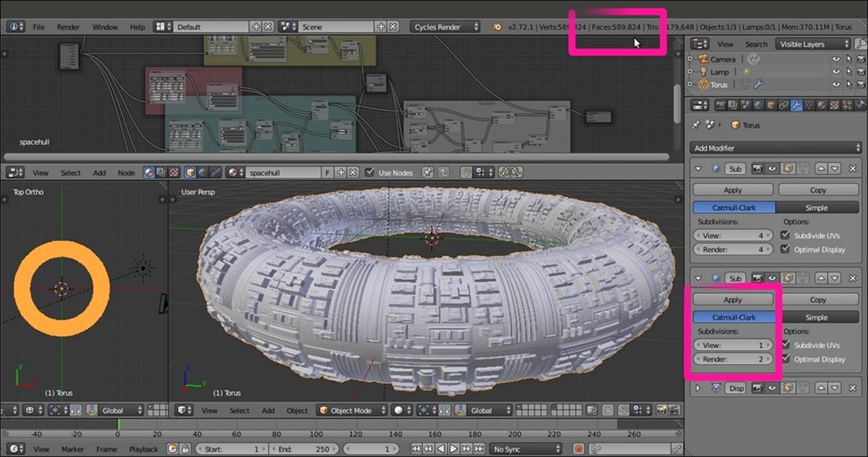
The Torus spaceship with the applied modifiers
See also
· The displacement technique on the Blender Artists forum, at http://blenderartists.org/forum/showthread.php?273033-Sculpting-with-UVs-and-displacements.
All materials on the site are licensed Creative Commons Attribution-Sharealike 3.0 Unported CC BY-SA 3.0 & GNU Free Documentation License (GFDL)
If you are the copyright holder of any material contained on our site and intend to remove it, please contact our site administrator for approval.
© 2016-2026 All site design rights belong to S.Y.A.