Blender Cycles: Materials and Textures Cookbook, Third Edition (2015)
Chapter 7. Subsurface Scattering in Cycles
In this chapter, we will cover the following recipes:
· Using the Subsurface Scattering shader node
· Simulating Subsurface Scattering in Cycles using the Translucent shader
· Simulating Subsurface Scattering in Cycles using the Vertex Color tool
· Simulating Subsurface Scattering in Cycles using the Ray Length output in the Light Path node
· Creating a fake Subsurface Scattering node group
Introduction
Subsurface Scattering is the effect of light not getting directly reflected by a surface but penetrating it and bouncing internally before getting absorbed or leaving the surface at a nearby point. In short, light is scattered.
The RGB channels of a surface color can have different scattering values, depending on the material; for example, for human skin the red component is more scattered (as a rough approximation, you could say that the values for the three channels are blue = 1, green = 2, and red = 4).
In Cycles, a true Subsurface Scattering node has been introduced in Blender 2.67. Since Version 2.72, it also works with the GPU (only in the Experimental feature set).
But sadly, it still has the common big Cycles problem—it takes a lot of samples to produce a noise-free rendering. In short, it's slow.
Besides the true node, there are other ways to simulate Subsurface Scattering in Cycles. All the recipes in this chapter faking the SSS effect use the Translucent shader node to achieve this effect, and shifting of colors is simulated by giving a main color to the translucent component. Keep in mind that even if the scattering effect in the true SSS node could be basically considered a sort of translucency effect, these tricks are not comparable to the real Subsurface Scattering effect. They are just ways to give the impression that light is being scattered through a material surface.
Also, depending on the recipe, you'll see that the effects of Subsurface Scattering can be quite different, and the more suitable method should be used according to the type of material you are going to create. The differences in these recipes are basically in the way translucency mixing is driven by different types of input.
Using the Subsurface Scattering shader node
Let's first see how the true Subsurface Scattering node works in Cycles, and an example is given in the following screenshot:
The Cycles SSS node
Getting ready
To see how the true Subsurface Scattering node works, let's first use it as the only component of the shader, and later mix it with a basic diffuse-glossy shader.
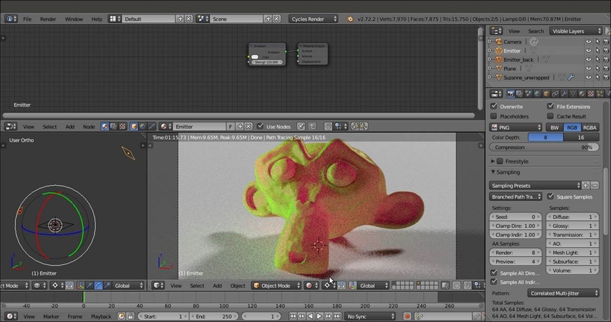
Let's start by setting the Plane under Suzanne as a light emitter to enhance the backlight effect of the SSS effect:
1. Start Blender and open the 9931OS_07_start.blend file, where there is an unwrapped Suzanne mesh leaning on a Plane, with two mesh-light emitters and the Camera as shown in the following screenshot:
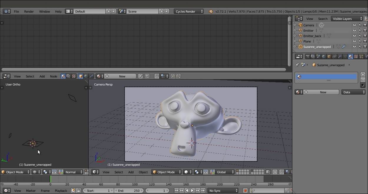
Screenshot of the provided 9931OS_07_start.blend file
2. Go to Outliner and select the Plane object. As you can see in the Node Editor window, it has an already set material called Plane.
3. Go to the Material window under the main Properties panel, and in the Surface subpanel, switch the Diffuse BSDF shader with an Emission shader as shown in the following screenshot:
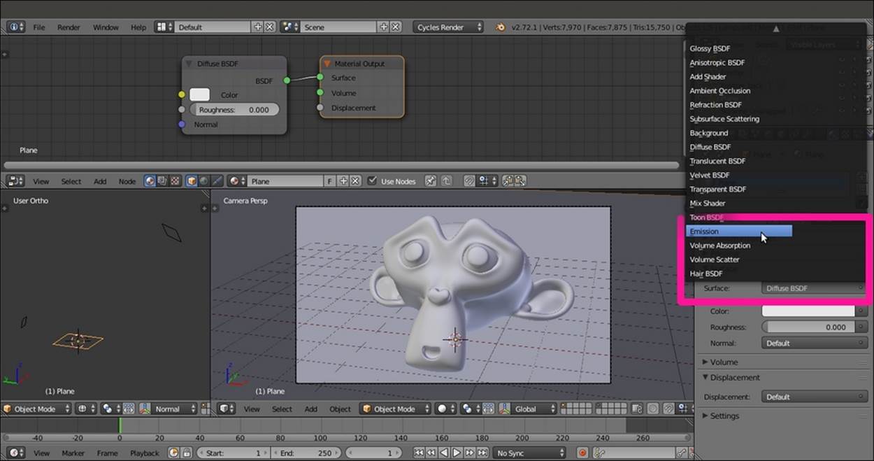
Switching the Diffuse BSDF shader with an Emission shader through the Material window
4. Set the Strength value to 5.000.
5. With the mouse arrow in the viewport, press Shift + Z to go to the Rendered view.
How to do it...
Now let's begin creating the SSS material using the following steps:
1. Select Suzanne and click on the New button in the Surface subpanel under the Material window in the main Properties panel, or in the Node Editor window.
2. Using only the Material window, replace the Diffuse BSDF shader with a Subsurface Scattering node as shown in the following screenshot:
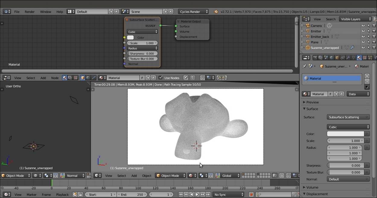
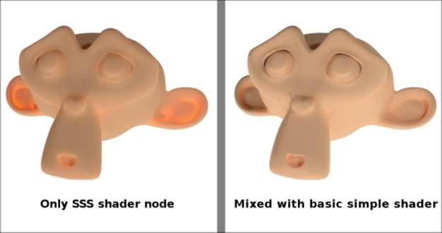
The Rendered preview of Suzanne with the SSS node as the material
As you can see, the scattering effect is clearly visible in the Rendered preview, but actually, it's so strong that all the facial features of poor Suzanne are confused and result in a jelly-like, muddish material.
By default, the Scale value of the Subsurface Scattering node is set to 1.000, evidently a bit too high for an object that is supposed to be 2 meters tall (remember that by default, one Blender unit is supposed to be equal to 1 real world meter).
3. Gradually lower the Scale parameter, either in Node Editor or in the Material window, to select a value in the range of 0.100 to 0.200. In my case, I arrived at 0.150. Now some of Suzanne's facial features are clearly discernible, as shown in the following screenshot:
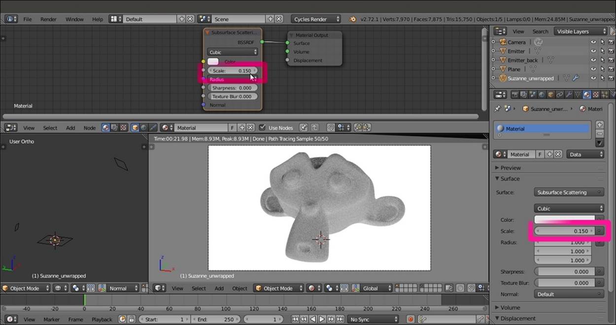
Modifying the SSS node's Scale value
4. Click on the Radius button on the node interface in the Node Editor window (or directly in the Material window), and change the values of R to 4.000, G to 2.000, and B to 1.000 as shown in the following screenshot:
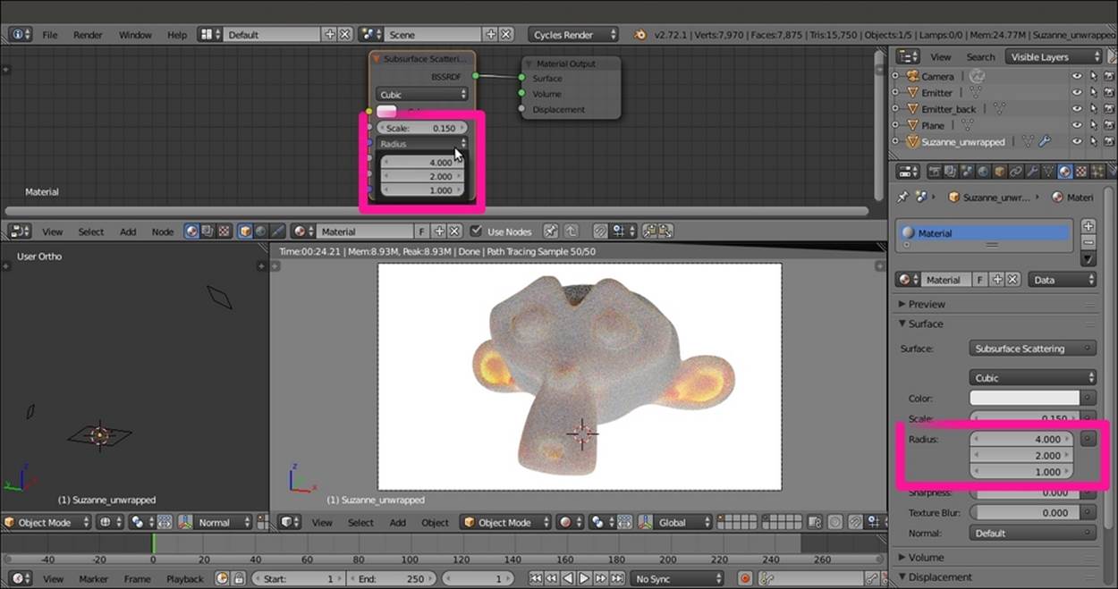
Modifying the SSS node's Radius values
5. Lower the Scale value to 0.070; set the Sharpness value to 1.000; and click on the Color box to set values of R to 1.000, G to 0.500, and B to 0.250.
6. Rename the material SSS_01 and save the file as SSS_material, as shown in the following screenshot:
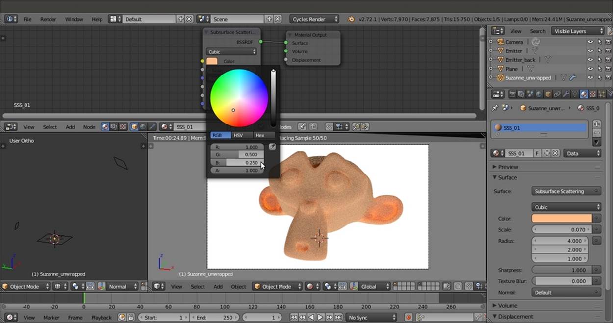
Setting a flesh color for the Suzanne SSS
7. Now click on the F icon to the right side of the Material datablock name to enable the fake user. Then click on the number 2 icon and rename the new material SSS_02. Enable the fake user for this material as well.
8. Add an Add Shader node (press Shift + A and navigate to Shader | Add Shader) and paste it between the SSS node and the Material Output node.
9. Add a Mix Shader node (press Shift + A and navigate to Shader | Mix Shader), and connect it to the first Shader input socket of the Add Shader node so that the previous connection coming from the SSS node automatically switch to the second Shaderinput socket.
10. Add a Diffuse BSDF node and a Glossy BSDF shader node (press Shift + A and navigate to Shader | …), and connect them to the first and to the second Shader input sockets of the Mix Shader node respectively, as shown in the following screenshot:
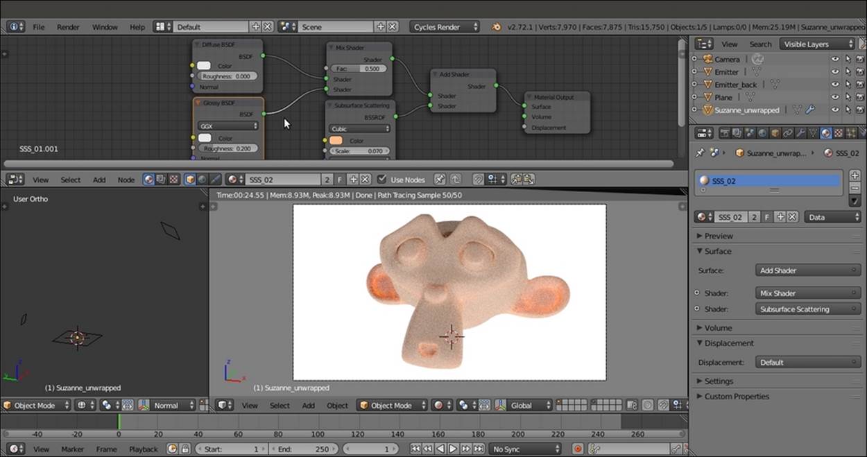
Adding the SSS node to a Diffuse-Glossy shader
11. Add a Layer Weight node (press Shift + A and navigate to Input | Layer Weight) and connect its Facing output to the Fac input socket of the Mix Shader node. Set the Blend value to 0.800.
12. Add an RGB node (press Shift + A and navigate to Input | RGB) and connect its output to the Color input sockets of the Diffuse BSDF, Glossy BSDF, and SSS nodes. Set the RGB node's Color values for R to 1.000, G to 0.500, and B to 0.250 as shown in the following screenshot:
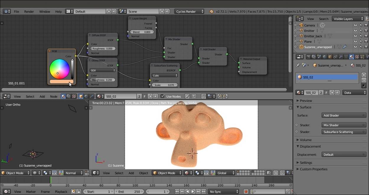
Setting the same flesh color for all the shader nodes
13. Save the file.
Let's try now a slightly different setting, with two sliders for the mixture of SSS and basic shaders. We will also give distinct colors to the Diffuse BSDF, Glossy BSDF, and SSS components of the shader to highlight their distribution on the mesh.
1. First, select the Plane object, and in the Material window, switch the Emission shader with a Diffuse BSDF shader node.
2. Reselect Suzanne and click on the number 2 button close to the Material datablock name. Rename the new material SSS_03. Then enable the fake user for this material as well.
3. Delete the RGB node. Then set the Diffuse BSDF shader node's Color values for R to 0.031, G to 0.800, and B to 0.000 (bright green); and the Glossy BSDF node's Color values for R to 0.646, G to 0.800, and B to 0.267 (yellow). Set the Glossy BSDF node'sRoughness value to 0.200 and Distribution to Beckmann. Set the Subsurface Scattering shader node's Color values for R to 0.800, G to 0.086, and B to 0.317 (a vivid pink). Change Falloff from Cubic to Gaussian.
4. Label the Mix Shader node as Mix Shader1, press Shift + D to duplicate it, and label the duplicate as Mix Shader2. Paste it between the Add Shader and Material Output nodes.
5. Connect the Mix Shader1 node's output to the first Shader input socket of the Mix Shader2 node so that the connection from the Add Shader automatically switches to the second Shader input socket.
6. Press Shift + D to duplicate the Mix Shader2 node, label the duplicated node as Mix Shader3, and paste it between the Mix Shader2 and the Material Output nodes.
7. Connect the output of the Subsurface Scattering node to the second Shader input socket of the Mix Shader3 node as shown in the following screenshot:
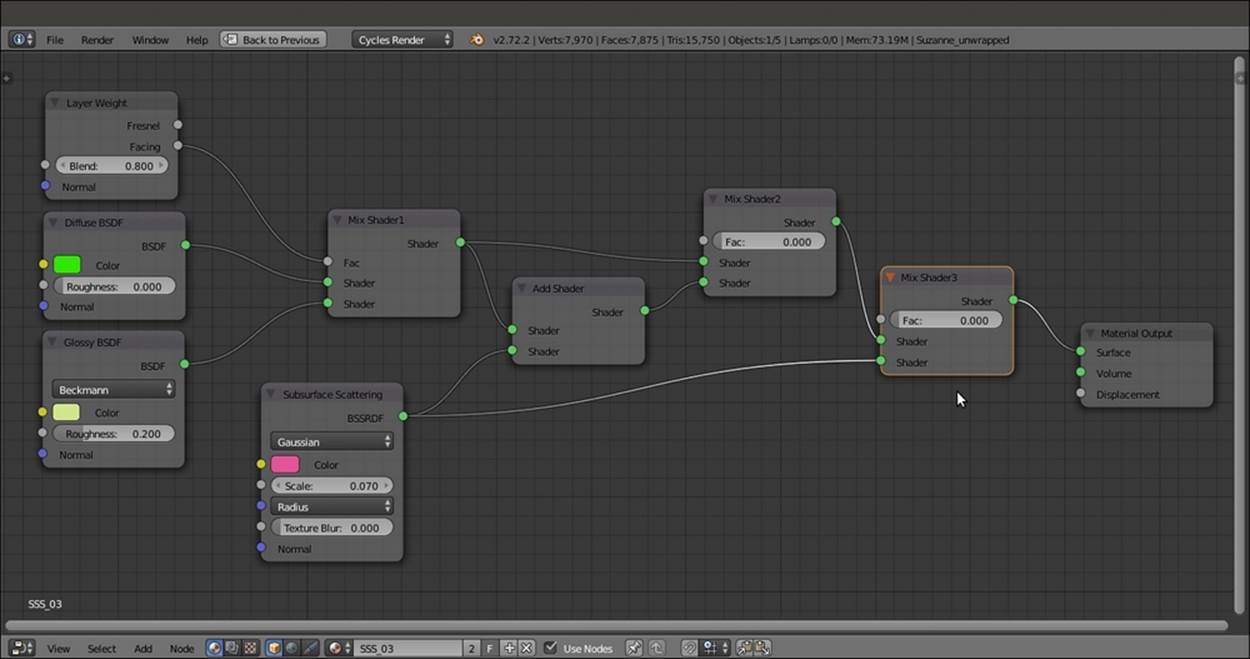
Adding one more Mix Shader node to further tweak the SSS amount
8. Save the file as SSS_material_02.blend.
How it works...
The scattering amount for the three RGB color channels is set in the Radius item on the node interface, while Scale is to set the dimensions the object would have in the real world. Starting with a default value of 1.000, the Scale value must usually be proportionally inverse lowered. The bigger the object desired in the real world, the lower the Scale value in the node. Otherwise, the scattering effect may become too strong.
The best way to mix the Subsurface Scattering node with the rest of any shader is by using the Add Shader node. However, with this node, it's not possible to establish the amount of influence of the SSS on the shader, so a trick must be performed. The Diffuse-Glossy component of the shader is again mixed with the output of the Add Shader node, through a Mix Shader node.
In the previously explained SSS_03 material, there are two Mix Shader nodes that can be used to tweak the influence of the effect. By raising their Fac values, it's also possible to switch from total absence to full scattering effect, as shown in the following compilation of screenshots:
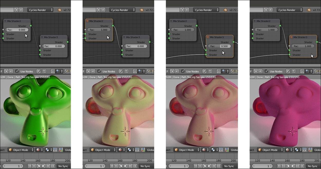
Different effects of different Fac values of the last Mix Shader node
See also
· Refer to http://en.wikipedia.org/wiki/Subsurface_scattering
Simulating Subsurface Scattering in Cycles using the Translucent shader
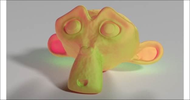
In this recipe, we will create a fake Subsurface Scattering material using the Translucent BSDF shader node as shown in the following screenshot:
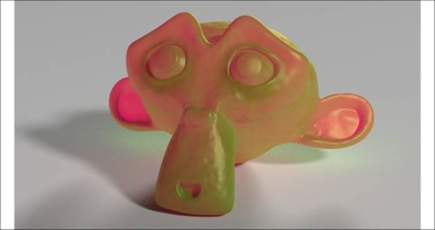
The rendered result of the fake SSS of this recipe
As someone suggested, this material could actually be quite good to make candles.
Getting ready
Start Blender and open the 9931OS_07_start.blend file:
1. Go to the Render window, and in the Sampling subpanel, click on the Method to sample lights and materials button to switch from Path Tracing to Branched Path Tracing. Enable the Square Samples item, and under AA Samples, set the Render value to 8. Finally, click on the Pattern button to select the Correlated Multi-Jitter item.
2. Save the file as 9931OS_SSS_translucent.blend.
How to do it...
Let's go ahead and create the material using the following steps:
1. Select the Suzanne object and click on the New button in the Node Editor window toolbar, or in the Material window to the right. Rename the material SSS_translucent.
2. In the Material window, switch the Diffuse BSDF shader with a Mix Shader node. In the first Shader slot, select a Diffuse BSDF shader again, and in the second slot, select a Glossy BSDF shader node.
3. Set the Diffuse BSDF shader node's Color values for R to 0.031, G to 0.800, and B to 0.000. Set the Glossy BSDF node's Color values for R to 0.646, G to 0.800, and B to 0.267. Set the Glossy BSDF node's Roughness value to 0.200 and Distribution toBeckmann.
4. Select the Mix Shader node and go to the Properties side-panel of the Node Editor window (if not present, move the mouse to the Node Editor window and press the N key to make it appear). In the Label slot inside the Node subpanel, label the Mix Shader node as Mix Shader1. Then set its Fac value to 0.200.
5. Add a new Mix Shader node (press Shift + A and navigate to Shader | Mix Shader), label it as Mix Shader2, and paste it between the Mix Shader1 node and the Material Output node.
6. Add a Translucent BSDF node (press Shift + A and navigate to Shader | Translucent BSDF) and connect it to the second Shader input socket of the Mix Shader2 node. Set the Color values of R to 0.800, G to 0.086, and B to 0.317.
7. Add a Texture Coordinate node (press Shift + A and navigate to Input | Texture Coordinate), a Mapping node (press Shift + A and navigate to Vector | Mapping), and a Noise Texture node (press Shift + A and navigate to Texture | Noise Texture).
8. Connect the UV output of the Texture Coordinate node to the Vector input socket of the Mapping node, and the output of this node to the Vector input socket of the Noise Texture node. Set the Noise Texture node's Scale value to 20.000.
9. Add a Bump node (press Shift + A and navigate to Vector | Bump) and connect the Color output of the Noise Texture node to the Height input socket of the Bump node. Then connect the Normal output of this node to the Normal input sockets of theDiffuse BSDF, Glossy BSDF, and Translucent BSDF nodes. Leave the Bump strength at 1.000.
10. Add a Fresnel node (press Shift + A and navigate to Input | Fresnel) and connect it to the Fac input socket of the Mix Shader2 node. Set the IOR value to 8.000 as shown in the following screenshot:
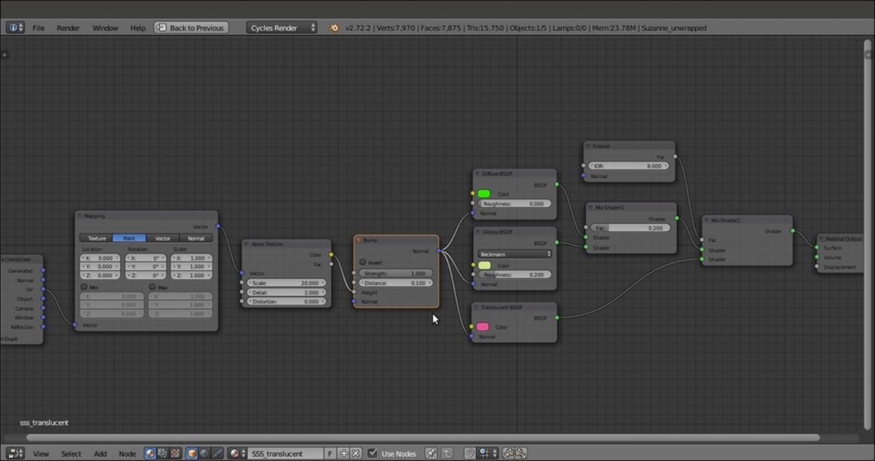
The overall view of the material network
11. Save the file.
How it works...
This is probably the simpler form of the fake Subsurface Scattering effect you can get in Cycles. It is obtained by simply blending a translucent effect with a basic Diffuse-Glossy shader. By varying the amount of the IOR value in the Fresnel node (set quite high as a starting point), it is possible to establish the amount of translucency on the mesh. We also added a Noise Texture bump effect to the material, just to make it appear more jelly-like.
Note that we gave almost complementary colors to the Diffuse BSDF and Translucent BSDF shaders to show the effect more clearly, but colors similar to each other can work better. Also note that the translucent effect actually follows the direction of the lighting. Try to rotate the Emitter and the Emitter_back planes around the Suzanne mesh to verify this in real time, through the Rendered view as shown in the following screenshot:
A preview of the fake SSS material lit from a different angle
Note
Note that for the three components of the shader (Diffuse BSDF, Glossy BSDF, and Translucent BSDF) we used (and will also use for the following recipes) the same colors of the SSS_03 material. This was done to make an easier comparison between the effects obtained in the recipes.
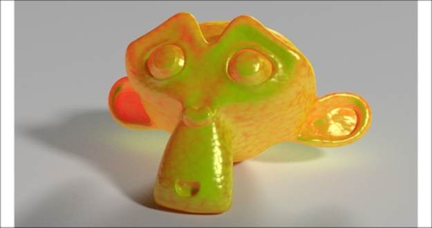
Simulating Subsurface Scattering in Cycles using the Vertex Color tool
In this recipe, we will create a fake Subsurface Scattering material as shown in the following screenshot, using the Vertex Color tool:
The Rendered result of the vertex color fake SSS material of this recipe
Getting ready
Start Blender and open the 9931OS_07_start.blend file.
1. Go to the Render window, and in the Sampling subpanel, click on the Method to sample lights and materials button to switch from Path Tracing to Branched Path Tracing. Enable the Square Samples item, and under AA Samples, set the Render value to 8. Finally, click on the Pattern button to select the Correlated Multi-Jitter item.
2. Select the Suzanne mesh, click on the Mode button in the Camera view toolbar, and choose Vertex Paint (or just press the V key). Now Suzanne goes into Vertex Paint mode.
3. Click on the Paint item to the left of the Mode button and select Dirty Vertex Colors. Then press T, and in the last operation subpanel (Dirty Vertex Color) at the bottom of the Tool Shelf panel, set Blur Strength to 0.50, Highlight Angle to 90°, and Dirt Angle to 90°. Enable the Dirt Only item as shown in the following screenshot:
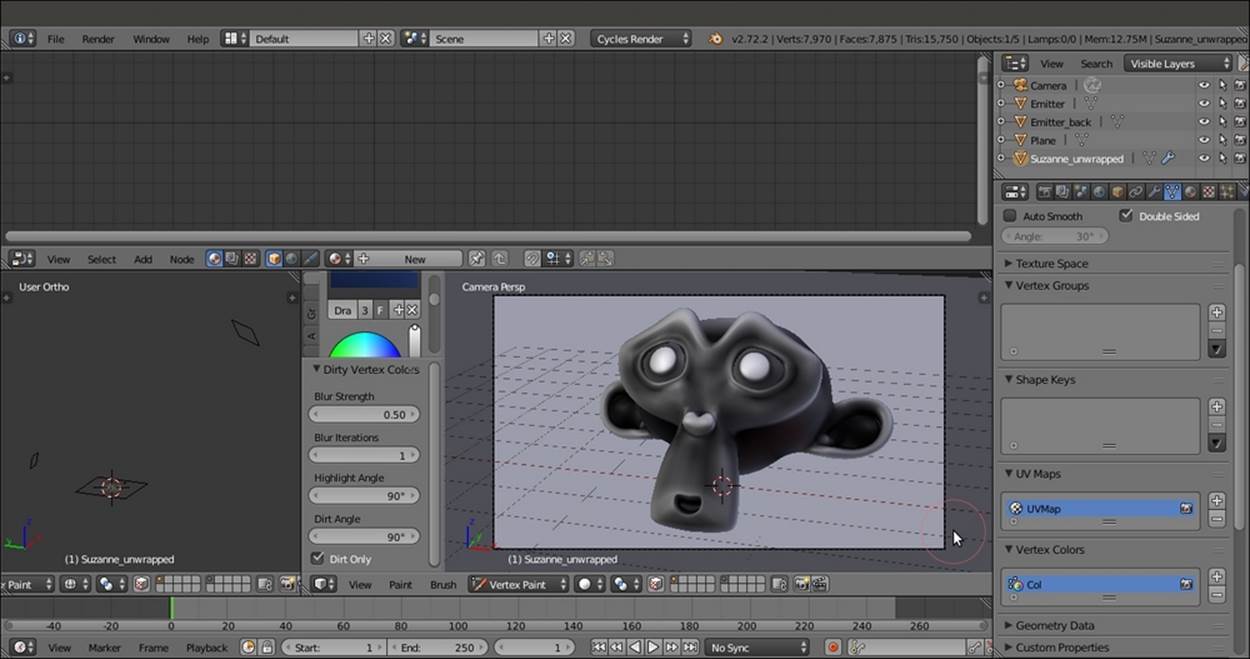
A screenshot of Suzanne in Vertex Paint mode and the Dirty Vertex Color values at the bottom of the Tool Shelf
The Suzanne mesh inside the 9931OS_07_start.blend file already had a Vertex Color layer named Col. With the previous procedure, we overwrote it.
4. Go to the Object data window under the main Properties panel to see it in the Vertex Colors subpanel. Then go back to Object Mode and press T to get rid of the Tool Shelf panel.
5. Save the file as 9931OS_07_SSS_vcol.blend.
How to do it...
After the vertex color preparation, let's go for the material itself by following these steps:
1. Click on the New button in the Node Editor window toolbar or in the Material window under the main Properties panel. Rename the material SSS_vcol.
2. In the Material window, switch the Diffuse BSDF shader with an Add Shader node. In the first Shader slot, select a Mix Shader node. In the second Shader slot, select a Translucent BSDF shader node. In the Properties side panel to the right of the Node Editor window, label the Mix Shader node as Mix Shader1.
3. Go to the Mix Shader1 node. In the first Shader slot, select a Diffuse BSDF shader node. In the second Shader slot, select a Glossy BSDF shader node. Set the Glossy BSDF node's Roughness value to 0.450 and Distribution to Beckmann.
4. Add a Fresnel node (press Shift + A and navigate to Input | Fresnel), connect it to the Fac input socket of the Mix Shader1 node, and set the IOR value to 3.850.
5. Set the Diffuse BSDF node's Color values for R to 0.031, G to 0.800, and B to 0.000 (the same bright green as in the Simulating Subsurface Scattering in Cycles using the Translucent shader recipe); and the Translucent BSDF node's Color values for R to0.800, G to 0.086, and B to 0.317 (the same pink as in the Using the Subsurface Scattering shader node recipe). Set the Glossy BSDF node's Color values for R to 0.646, G to 0.800, and B to 0.267, again it's the same yellowish color as in the Using the Subsurface Scattering shader node recipe).
6. Add a Texture Coordinate node (press Shift + A and navigate to Input | Texture Coordinate), a Mapping node (press Shift + A and navigate to Vector | Mapping), and a Noise Texture node (press Shift + A and navigate to Texture | Noise Texture).
7. Connect the UV output of the Texture Coordinate node to the Vector input socket of the Mapping node, and the output of this node to the Vector input socket of the Noise Texture node. Set the Noise Texture node's Scale value to 20.000.
8. Add a Bump node (press Shift + A and navigate to Vector | Bump) and connect the Color output of the Noise Texture node to the Height input socket of the Bump node. Then connect the Normal output of this node to the Normal input sockets of theDiffuse BSDF, Glossy BSDF, and Translucent BSDF nodes.
9. Add a new Mix Shader node (press Shift + A and navigate to Shader | Mix Shader), label it as Mix Shader2, and paste it between the Add Shader and Material Output nodes. Then move the connection from the Add Shader node to the second Shader input socket, and connect the output of the Mix Shader1 node to the first Shader input socket of the Mix Shader2 node.
10. Add an Attribute node (press Shift + A and navigate to Input | Attribute) and a ColorRamp node (press Shift + A and navigate to Converter | ColorRamp). In the Name slot of the Attribute node, write the vertex color layer name, that is, Col. Then connect the Color output of Attribute node to the Fac input socket of the ColorRamp node. In the ColorRamp node, move the white color stop to 0.350 position.
11. Add an RGB Curves node (press Shift + A and navigate to Color | RGB Curves) and connect the Color output of the ColorRamp node to the Color input socket of this node. Then connect its Color output to the Fac input socket of the Mix Shader2 node.
12. Inside the RGB Curves node's interface window, move the first curve control point coordinate values for X to 0.00000 and Y to 0.88125, and the second point coordinate values for X to 1.00000 and Y to 1.00000.
13. Save the file. The overall network will be as shown in the following screenshot:
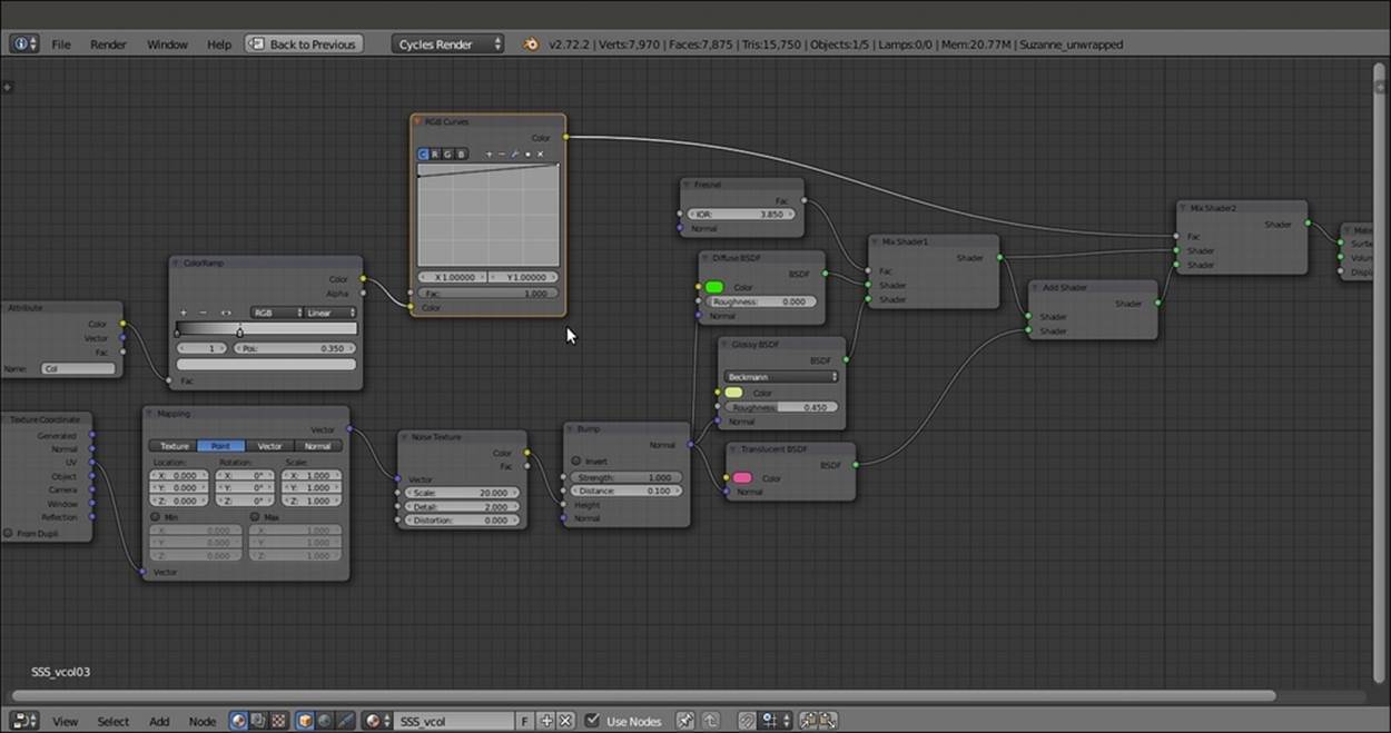
The overall network; note the Vertex Color output intensified by ColorRamp and RGB Curves nodes
How it works...
Compared to the former recipe, in this case, we used information about the Vertex Color, enhanced by the ColorRamp node, to drive the mixing of the translucency with the other components of the shader. It's clear that the final result is largely due to vertex painting. We obtained this result quickly through the Dirty Vertex Color tool, but that could also be painted by hands (imagine you're painting a mask for a skull under the face skin).
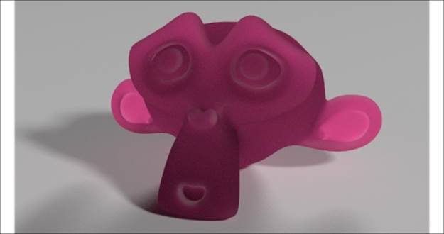
Simulating Subsurface Scattering in Cycles using the Ray Length output in the Light Path node
In this recipe, we will create a fake Subsurface Scattering material using the Ray Length output of the Light Path node.
The Rendered result of the fake SSS material of this recipe
Getting ready
Start Blender and open the 9931OS_07_start.blend file.
1. Go to the Render window, and in the Sampling subpanel, click on the Method to sample lights and materials button to switch from Path Tracing to Branched Path Tracing. Enable the Square Samples item, and under AA Samples, set the Render value to 8. Finally, click on the Pattern button to select the Correlated Multi-Jitter item.
2. Save the file as 9931OS_07_SSS_raylength.blend.
How to do it...
Let's create the material using the following steps:
1. Select the Suzanne object. Click on the New button in the Node Editor window toolbar or in the Material window to the right of the screen. Rename the material SSS_raylength.
2. In the Material window, switch the Diffuse BSDF shader with a Mix Shader node. Label it as Mix Shader1. In its first Shader slot, select a Diffuse BSDF shader. In its second Shader slot, select a new Mix Shader node. Label this node as Mix Shader2.
3. Go to the Mix Shader2 node. In its first Shader slot, select a new Mix Shader node and label it as Mix Shader3. In the second Shader slot, select a Glossy BSDF node.
4. Add a Layer Weight node (press Shift + A and navigate to Input | Layer Weight) and connect its Facing output to the Fac input socket of the Mix Shader1 node. Set the Blend value to 0.950.
5. Set the Fac value of the Mix Shader2 node to 0.200 and the Fac value of the Mix Shader3 node to 0.700. Set the Glossy BSDF node's Roughness to 0.100.
6. Connect the Diffuse BSDF node output to the first Shader input socket of the Mix Shader3 node. Add an Add Shader node (press Shift + A and navigate to Shader | Add Shader) and connect it to the second Shader input socket of the Mix Shader3 node.
7. Go to the Add Shader node, and in the first Shader slot, select the last Mix Shader node. Label it as Mix Shader4. In the second Shader slot, select a Translucent BSDF shader node.
8. Connect the output of the Diffuse BSDF node to the first Shader input socket of the Mix Shader4 node, and the output of the Translucent BSDF node to the second Shader input socket.
9. Set the Diffuse BSDF shader node's Color values for R to 0.031, G to 0.800, and B to 0.000; the Glossy BSDF shader node's Color values for R to 0.646, G to 0.800, and B to 0.267; and the Translucent BSDF shader node's Color values for R to 0.800, G to0.086, and B to 0.317.
10. Add a Voronoi Texture node (press Shift + A and navigate to Texture | Voronoi Texture) and a Bump node (press Shift + A and navigate to Vector | Bump). Connect the Color output of the Voronoi Texture node to the Height input socket of the Bumpnode and the Normal output of this node to the Normal input sockets of the Diffuse BSDF, Glossy BSDF, and Translucent BSDF nodes. Set the Voronoi Texture node's Scale value to 32.600 and the Bump node's Strength value to 0.100. Then enable theInvert item in the Bump node.
11. Add a Light Path node (press Shift + A and navigate to Input | Light Path) and a Math node (press Shift + A and navigate to Converter | Math). Set the Math node's Operation to Multiply. Connect the Ray Length output of the Light Path node to the firstValue input socket of the Math node. Then set the second Value input socket to -8.000.
12. Press Shift + D to duplicate the Math node. Set Operation to Power. Connect the output of the Multiply math node to the first Value input socket of this node. Set the second Value input socket to 3.000. Enable the Clamp item.
13. Press Shift + D to duplicate the Power-Math node, set Operation to Add, and connect the output of the Power node to its first Value input socket. Connect its output to the Fac input socket of the Mix Shader4 node.
14. Connect the Fac output of the Voronoi Texture node to the second Value input socket of the Add-Math node.
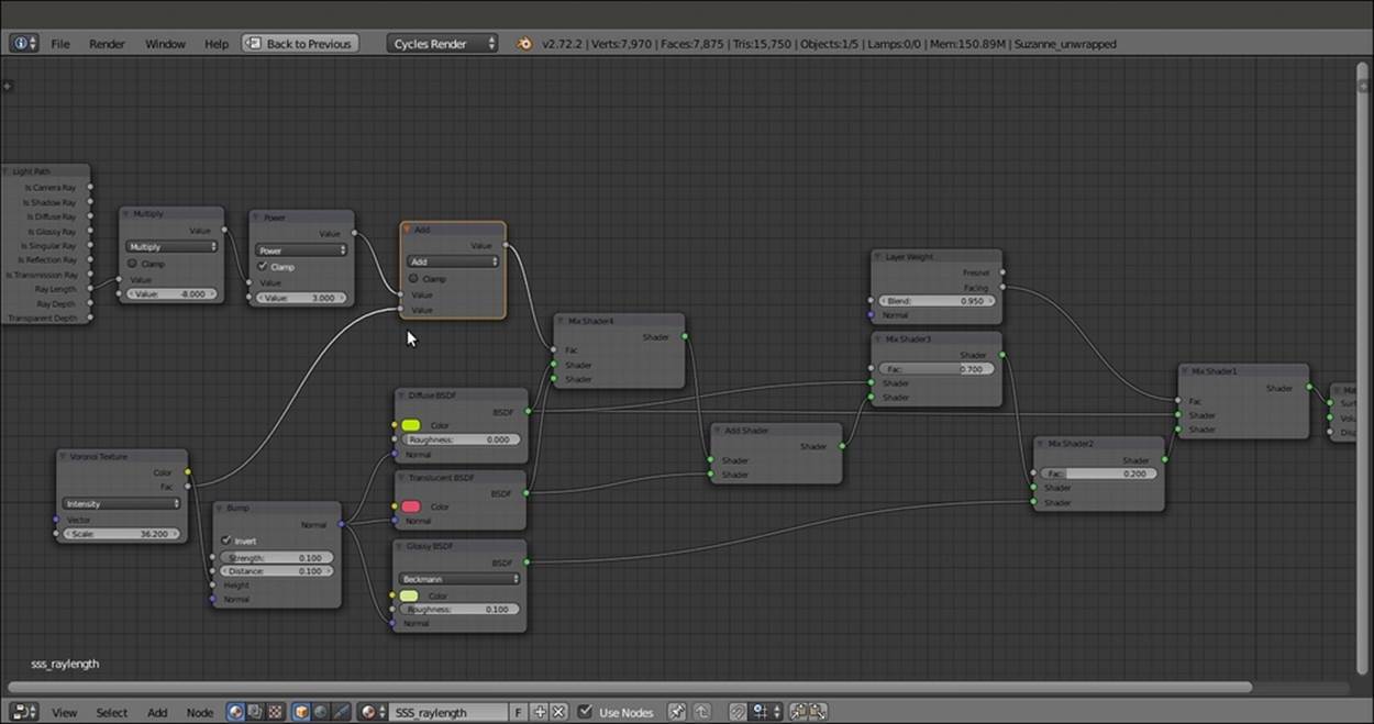
The completed network of the material
15. Save the file.
How it works...
In this recipe, we used the Ray Length output of the Light Path node to drive the amount of translucency on the mesh. Ray Length does exactly what its name suggests. It returns the length of a light ray passing through an object. So basically, it is possible for Cycles to know the thickness of a mesh. On the thicker parts, the translucency will show less or even for nothing, whereas it will be more visible on the thinner parts of the mesh.
Note
Note that in the shader network, the Ray Length output was intensified by a set of Math nodes and added to the Voronoi Texture node's output. Then it was connected to the factor input of the Mix Shader node to drive the blending of the Diffuse and of the Translucent components.
Creating a fake Subsurface Scattering node group
In this recipe, we will create a fake Subsurface Scattering node group that can be mixed with other nodes to add the fake scattering effect to a material. In this screenshot, you can see the effect of the Subsurface Scattering node alone on the Suzanne mesh:
The rendered result of the fake SSS node group assigned to Suzanne
In the following screenshot, you can see the effect of the node group added to the usual basic shader material:

Mixed with a Diffuse-Glossy shader
Again, we will use the colors of the previous recipes.
Getting ready
Start Blender and open the 9931OS_07_start.blend file.
1. Go to the Render window, and in the Sampling subpanel, click on the Method to sample lights and materials button to switch from Path Tracing to Branched Path Tracing. Enable the Square Samples item and under AA Samples, set the Render value to 8. Finally, click on the Pattern button to select the Correlated Multi-Jitter option.
2. Save the file as 9931OS_07_SSS_ngroup.blend.
How to do it...
Now let's create the material using the following steps:
1. Click on the New button in the Node Editor window toolbar or in the Material window under the main Properties panel. In the Node Editor window, delete the Diffuse BSDF shader node.
2. Add a Light Path node (press Shift + A and navigate to Input | Light Path) and a Geometry node (press Shift + A and navigate to Input | Geometry).
3. Add a Math node (press Shift + A and navigate to Converter | Math). Set Operation to Multiply and connect the Ray Length output of the Light Path node to the first Value input socket. Set the second Value input socket to -1.500.
4. Press Shift + D to duplicate the Multiply-Math node, and set Operation to Power. Connect the Multiply-Math node output to the second Value input socket of the Power node. Set the first Value to 20.000.
5. Press Shift + D to duplicate the Power node, and set Operation to Add. Connect the Power node output to the second Value input socket of the Add-Math node, and the Is Camera Ray output of the Light Path node to the first Value input socket of theAdd-Math node.
6. Press Shift + D to duplicate the Add node. Set the Operation to Minimum. Connect the output of the Add node to the first Value input socket of the Minimum node, and set the second Value input socket to 1.000.
7. Press Shift + D to duplicate the Power node, and place it after the Minimum node. Connect the output of the Minimum node to the first Value input socket of the duplicated Power node.
8. Add a Value node (press Shift + A and navigate to Input | Value), label it as Contrast, and connect its output to the second Value input socket of the last Power-Math node. Set Value to 1.200.
9. Press Shift + D to duplicate any of the Math nodes, set Operation to Subtract, and connect the Backfacing output of the Geometry node to its second Value input socket. Set the first Value input socket to 1.000.
10. Press Shift + D to duplicate the Subtract node, set Operation to Add, and paste it between the first Add and Minimum nodes. Connect the output of the Subtract node to the second Value input socket of the last Add node.
11. Add a ColorRamp node (press Shift + A and navigate to Converter | ColorRamp) and connect the output of the last Power-Math node to its Fac input socket. Add a Translucent BSDF node (press Shift + A and navigate to Shader | Translucent BSDF) and connect the Color output of the ColorRamp node to its Color input socket.
12. Set the ColorRamp node's Interpolation to B-Spline. Click on the Add button to add a new stop with Color values for R as 0.500, G as 0.500, and B as 0.500 at the position of 0.500.
13. Add a MixRGB node (press Shift + A and navigate to Color | MixRGB). Set Blend Type to Overlay and the Fac value to 1.000. Connect the Color output of the ColorRamp node to the Color1 input socket. Set Color2 values for R as 0.500, G as 0.054, and Bas 0.077.
14. Connect the Color output of the Overlay node to the Color input socket of the Translucent BSDF node. Connect the output of the Translucent BSDF node to the Surface input socket of the Material Output node as shown in the following screenshot:
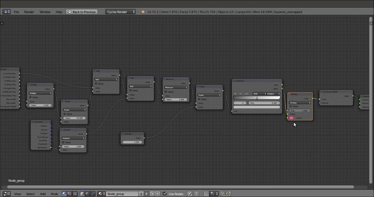
The network to be grouped
15. Now select all the nodes except the Value and Material Output nodes. Press Ctrl + G to create a Node Group.
16. Rename the exposed input socket to the left of the node group as Contrast, set the value on the group interface, and then delete the original Value node.
17. Click and drag the Color2 socket of the Overlay node to the empty socket on the Group Input node, and rename the exposed socket as Subsurface Scattering_color. Then click and drag the Normal socket of the Translucent BSDF shader node to the empty socket as shown in the following screenshot:
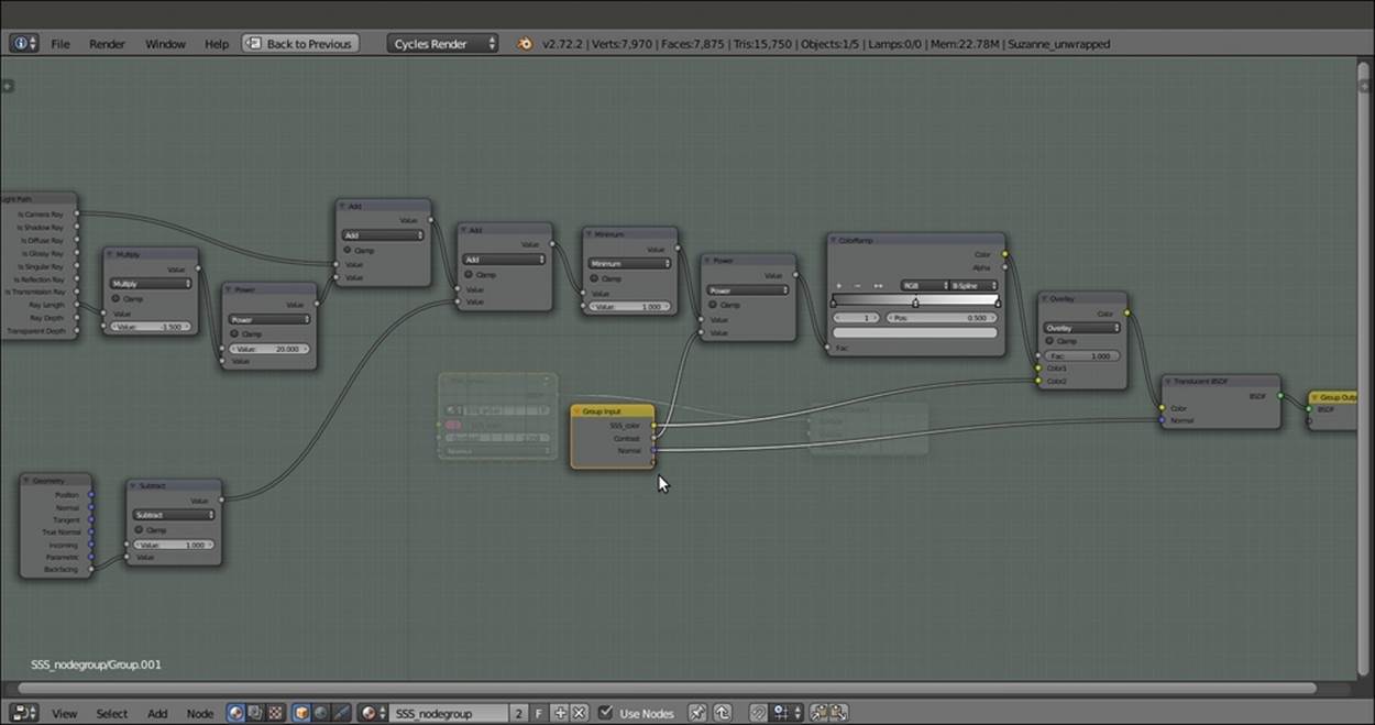
The network inside the open-for-editing node group
18. Press Tab to close the node group, and rename it SSS_group.
So now, we have made the Subsurface Scattering node group, ready to be mixed with any surface material.
Let's now create a simple material to mix the node group using the following steps:
1. Add a Mix Shader node, a Diffuse BSDF node, and a Glossy BSDF shader node (press Shift + A and navigate to Shader | ...). Connect the Diffuse BSDF node output to the first Shader input socket of the Mix Shader node and the Glossy BSDF shader output to the second Shader input socket.
2. Connect the Mix Shader output to the Surface input socket of the Material Output node.
3. Set the Color values of the Diffuse BSDF shader node for R to 0.031, G to 0.800, and B to 0.000. Set the Color values of the Glossy BSDF node for R to 0.646, G to 0.800, and B to 0.267.
4. Add a Voronoi Texture node (press Shift + A and navigate to Texture | Voronoi Texture) and a Bump node (press Shift + A and navigate to Vector | Bump). Connect the Fac output of the texture node to the Height input socket of the Bump node, and theNormal output of this node to the Normal input sockets of the Diffuse BSDF and Glossy BSDF shaders, and also of the SSS_group node group.
5. Set the Bump node's Strength to 0.150 and enable the Invert item. Set the Voronoi Texture node's Scale value to 22.500.
6. Add a Fresnel node (press Shift + A and navigate to Input | Fresnel) and connect it to the Fac input socket of the Mix Shader node. Set the IOR value to 3.250.
Now let's simply add the Subsurface Scattering node group:
1. Add an Add Shader node (press Shift + A and navigate to Shader | Add Shader) and paste it between the Mix Shader node and the Material Output node. Switch the connection from the first socket to the second socket (this is actually not required in this case because the shaders are added anyway).
2. Connect the output of the SSS_group node to the first socket of the Add Shader node as shown in the following screenshot:
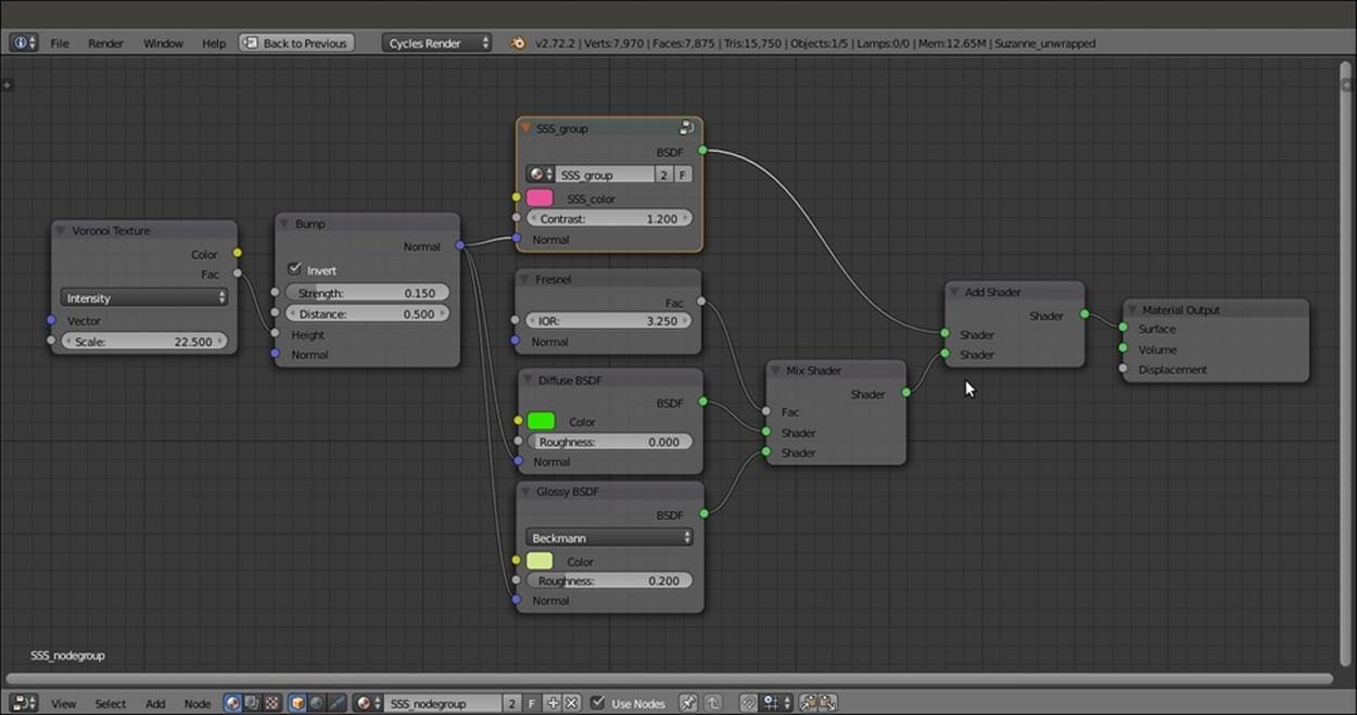
The SSS node group added to the diffuse and glossy components of an average shader
How it works...
The key of this material is obviously the Light Path node, with its several kinds of output. In this case, we are interested in two of them:
· The Ray Length and Is Camera Ray output of the Light Path node are added together. Ray Length defines the thickness of the mesh, and it's also clamped by the first Multiply node and the Power node. The Is Camera Ray output gets Cycles to render only those surface points that are directly hit by light rays emerging from the Camera. When added to each other, the two types of output produce a stencil effect, gray-scale values distributed according to the thickness of the mesh.
· Next, the Backfacing output of the Geometry node is added to take into consideration the color of the back mesh faces. All of this is multiplied by the second Power node for the Contrast value and further clamped by the ColorRamp node.
· At this point, the result is mixed with the Subsurface Scattering_color output by the Overlay node, and finally connected to the Color input socket of the Translucent BSDF shader, resulting in the semi-transparent-looking shader of the first image at the beginning of this recipe.
All materials on the site are licensed Creative Commons Attribution-Sharealike 3.0 Unported CC BY-SA 3.0 & GNU Free Documentation License (GFDL)
If you are the copyright holder of any material contained on our site and intend to remove it, please contact our site administrator for approval.
© 2016-2026 All site design rights belong to S.Y.A.