Emerging Trends in Image Processing, Computer Vision, and Pattern Recognition, 1st Edition (2015)
Part I. Image and Signal Processing
Chapter 9. Highlight image filter significantly improves optical character recognition on text images 
Iulia Stirb Computer and Software Engineering Department, “Politehnica” University of Timisoara, Timisoara, Romania
Abstract
Image filtering is changing the appearance of an image by altering the colors of the pixels. Increasing the contrast as well as adding a variety of special effects to images are some of the results of applying filters. In order to obtain a high success rate of OCR (optical character recognition) performed on text images, the main target of filters is, however, to reduce the noise around characters in the image. Thereby, I created two new nonlinear efficient image filters (for RGB and ARGB images) and elaborated the optimization technique suitable for each of the filters in order to make them perform faster. The first filter, namely, Smart Contrast, increases the contrast of the image in a way depending on the value of each component (Red, Green, and Blue) of each pixel in the image. The second image filter, called Highlight, produces a remarkable increase in OCR success rate on the filtered text images. As Highlight filter is carried out, the implementation differs from all other known filters, while the visual effect on the images can be described as a combination between increased contrast as said before with other two visual effect: sharpening and highlighting the edges (of the characters). Precisely, combining these specific visual effects on the resulting image makes Highlight filter so powerful in improving OCR on text images.
Keywords
Contrast
Filter
Highlight
Image
OCR
NOMENCLATURE
LoG Laplacian of Gaussian
OCR optical character recognition
HD high dimension
1 Introduction
Many often, the choice of the image filter is done nonautomatically, by humans, as a result of observing the characteristics of the image (color of the text and background, shape or thickness of characters in the image, noise around characters). Researches reveal that specific filters are used for certain images. For instance, if the original image is blurred and the expected result is an image with higher clarity than Sharpen filter can be used and on the other hand, if less level of details is desired in the resulting image, then Blur filter would be the right choice.
The process of selecting the scale of a filter in order to perform edge detection over the image can be automated [1]. Overall, researches have been carried out regarding the automated selection of the parameters of many filters [2, p. 86]. In other words, once the proper filter to apply to the image has been choose by humans, the filter’s parameter is selected by a computer depending on the desired output image.
However, an automated analysis of the image properties in order to select the proper filters to be applied to it would be a complicated, expensive, and time-consuming process since the analysis depends on many factors (e.g., noise, clarity, or contrast of the input image).
The image filter which I named it “Highlight” is designed to be a universal filter for improving optical character recognition (OCR) rate of success on a large variety of text images and because of its large applicability it avoids the automated selection of the proper filter to be applied to a specific image.
In the Section 1, the article contains the description of the new image filter, namely, Smart Contrast, and afterwards, one major section in which the new image filter, entitled Highlight, is detailed and snippets of code from its implementation are provided. Both sections include an overview on some already existing filters such as the nonoptimized and optimized version (using “color matrix” technique) of Contrast image filter. In the following section, the optimization technique (i.e., “byte buffer” technique) of Smart Contrast and Highlight image filters is presented, but nevertheless, “byte buffer” techniques can be applied to any image filter. Conclusions section presents the major benefit Highlight image filter brings in improving the success rate of OCR in comparison to other filters and describes the visual effect of Highlight filter on images.
1.1 Properties of Highlight Image Filter
Highlight image filter detects the edges of the features in the image, i.e., edges of the characters in a text image, highlights and sharpens the text, and increases the contrast in a selective manner (in a way similar to Smart Contrast image filter), that is predominantly in the areas of sudden change in color intensity like it is in the case of the edges of the characters [3, pp. 391-397].
What Highlight filter brings new regarding the way contrast is normally done is that it performs a selection between two types of transformations and chooses the proper one to be applied. Instead of simply applying the same transformation to all components of each pixel like Contrast filter would do, the selection is done for each component (e.g., Red) of each pixel separately. This improvement made by Highlight image filter (and Smart Contrast as well) regarding the way contrast is increased produces even more contrast between the text in an image and the background in cases when this is needed such as when the color of the text is close to the color of the background making the text more visible than it would be by simply applying Contrast filter.
2 Description of smart contrast image filter
Smart Contrast filter compares the value of each component (e.g., Red) of each pixel with 127 (255/2, note that the range in which the components Red, Green, and Blue vary is 0-255 when it comes to RGB images as in this case) and if the value is less than 127, it performs a certain transformation to that specific component, if greater it performs a different transformation. As a case study, if an image that contains some text is considered and the color of the text would be (Rt,Gt,Bt) = (126,126,125) and the color of the background would be (Rb,Gb,Bb) = (130,137,136), then the colors would be pretty similar, so the text would be hard to recognize even for the human eye. In this case, which may often occurs, Smart Contrast filter decreases more the color of the text and increases more the color of the background than Contrast filter would do, making the text more visible and more easily to be detected by OCR. Thus, Smart Contrast keeps the good work Contrast filter does and, in addition, produces good results for edge cases.
2.1 Contrast Image Filter
Contrast filter is based on the transformation in Equations (1a)–(1c) where contrast is the contrast scale (the degree to which the contrast is increased) and red, green, and blue are the values of the components of a pixel:
![]() (1a)
(1a)
![]() (1b)
(1b)
![]() (1c)
(1c)
The graphic representation for transformation in Equations (1a)–(1c) is represented in Figure 1 (blue plot). In the same figure, the identity function it is also drawn (green plot) to spot how pixel component values increase or decrease according to the transformation. If the value of the pixel component is less than zero, it is set to zero and if it is greater than 255, it is set to 255.
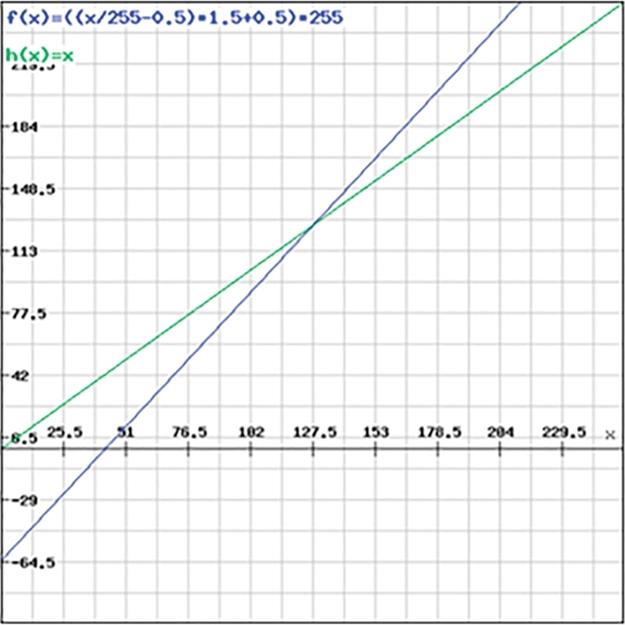
FIGURE 1 Contrast filter transformation (function f).
So far, the same transformation is being applied to all components of each pixel. Thus, this is how Contrast filter performs; however, the property is also specific to many other filters (e.g., Invert, Color).
2.1.1 Description of the optimized implementation of contrast image filter using “color matrix” technique
Figure 2 presents an example of how “color matrix” optimization technique performs on one pixel having the, e.g., Red component equal to 51 and scaled down to 0.2 (= 51/255). The input vector represents the original pixel with its components Red, Green, Blue, and Alpha in this order [4,5]. The values of the components vary in a range from 0 (= 0/255) to 1 (= 255/255). The last element of the input vector is used for additional computations, if needed. After the calculation of the output array, the values are scaled again to the fit into the interval [0;255].
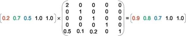
FIGURE 2 ColorMatrix example of multiplication for one pixel.
The matrix content is specific to each filter separately and exemplified in Figure 3 for Contrast image filter. diff is obtained as in Equation (2) by refactoring Equations (1a)–(1c), and scale is the desired degree of Contrast (usually varies from 1 to 6). The fact that diff is computed only once for all pixels in the image before the filter is actually applied to the image saves a great amount of execution time spent per pixel, compared to the standard version of contrast that uses the transformation in Equations (1a)–(1c). To be more specific, this optimization technique implies successive divisions (for scaling all pixels values to the range [0;1]) and multiplications (for scaling all pixels values back to range [0;255]) which can be performed in parallel on several floating-point units provided by the underlying hardware architecture, which considerably decreases the execution time (Contrast image filter was speedup 8 times on HD images):
![]() (2)
(2)
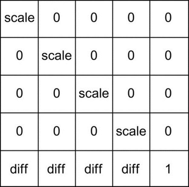
FIGURE 3 Color matrix for Contrast image filter.
The main advantages of using “color matrix” optimization technique are the significant increase in execution time (8 times for Contrast filter) and the fact that the contrast of each component, e.g., Red can be increased in a different manner than another, e.g., Green.
The drawback of “color matrix” optimization techniques is that the one and the same set of transformations must be applied to all pixels in the image.
This optimization technique should be used when the image filter performs many computations per pixel such as Contrast.
2.2 New Image Filter: Smart Contrast
Smart Contrast performs two similar transformations depending on the value of the pixel component. For less than 127 (255/2) values, the formula is illustrated by
![]() (3)
(3)
Equation (4) shows the formula for values of the pixel components greater than 127.
![]() (4)
(4)
Value 127 is the threshold for Smart Contrast filter and the value of the threshold is chosen to be the median value in the range from 0 to 255 (i.e., 0 is lowest value and 255 the highest value of color intensity).
As a remark, the same pixel could be the result of applying two types of transformations to its components (e.g., Red, Green, or Blue). For instance, we could focus on an arbitrary pixel that has the coordinates (x,y) relative to the upper-left corner of the image. By assuming that Equation (3) is applied to the Red component of that pixel and Equation (4) is applied to the Blue component of the same pixel, we are facing a possible situation that could arise in the algorithm. Despite this fact exemplified before, not more than one transformation will be applied to a single component of a pixel (e.g., Red component could not possibly be the result of applying Equations (3) and (4), it will have to be either (3) or (4), but not both).
Furthermore, two different pixels could be the result of applying different transformations to the same component of the two pixels, e.g., the filtered Red component of the first pixel that has the coordinates (x1,y1) could be the result of applying Equation (3) and the filtered Red component of the second pixel that has the coordinates (x2,y2) could be the result of applying Equation (4). The graphic representation of the two transformations is shown in Figure 4(a), together with the identity function that helps in spotting the way pixel components are increased or decreased. Figure 4(b) highlights the difference between Contrast and Smart Contrast algorithms. If the value of the pixel component is less than threshold 127, the blue plot describes the transformation that is applied to that certain component, else the transformation shown in the red plot is the one applied to the component.

FIGURE 4 (a) Smart Contrast transformation (functions f and g) and the identity function h. (b) Smart Contrast (functions f and g) and contrast transformation (function h).
Since the one and the same transformation is not applied to all pixels in the image, the “color matrix” optimization techniques cannot be used when it comes to Smart Contrast image filter. Another optimization technique is applied to this filter, as well as to the further image filter, namely, Highlight, and will be detailed at the end of the description of both image filters.
Best OCR rate of success for the filtered images using Smart Contrast filter is produced when contrast scale is set to 1.5.
2.3 Visual Result of Applying Smart Contrast on Images
Smart Contrast filter produces the results shown in Figure 5. The results produced by Contrast filter are also shown in Figure 5 in order to spot the improvements made by Smart Contrast. The effect of applying Smart Contrast filter would be that, in most of the cases, contrast is increased in areas where edges of the objects (e.g., characters) appear in the image. Exceptions occur when the color of the characters is close to the color of the background, but both are close to either the lowest color intensity or the highest color intensity. This drawback is solved in Highlight filter.
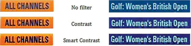
FIGURE 5 The visual effect of Smart Contrast image filter.
3 Description of highlight image filter
This filter decreases more the values of pixel components (i.e., Red, Green, and Blue) that are less than 127 (using Equation 3) and increases more the values greater than 127 (using Equation 4) than Contrast filter would do. OCR benefits from Highlight filter’s improved way of contrasting the image (which is similar to how Smart Contrast filter performs in the way that it chooses between the same transformations as Smart Contrast) and from the other two properties that are sharpening and highlighting the edges of the features in the image (e.g., the characters).
Highlight filter emphasized the areas of rapid intensity change (i.e., edges) like LoG (Laplacian of Gaussian) filter would do. Once the edges are detected, they are being sharpened, which would produce a visual effect that is similar to what Sharpen filter would do to an image. Still, the implementation of Highlight image filter has no similarities with Sharpen and LoG filters’ implementation.
In addition, Highlight filter creates shadows behind characters (the color of the shadows contrasts with the color of the characters) and those shadows create a uniformly colored area that covers the noise around characters and this way it leaves no isolated noise pixel around the text that could damage the correctness of the OCR process. In a specific stage of it, the OCR engine transforms the colored filtered text image into a black and white one in which the contours of the characters are unbroken because of the uniformly colored shadows, turned to whether black or white, that fill the characters (i.e., shadows will be white if the characters are turned to white, and respectively, black if the characters are turned to black).
Precisely, all these combined properties of Highlight image filter, namely, selective contrast, sharpening and highlighting the characters, and creating contrasting shadows behind text, contribute to a high success rate of OCR on text images.
3.1 Description of the Image Filters’ Visual Effects That Are Included in Highlight’s Visual Effect
Smart Contrast produces an effect similar to what Contrast does, that is increasing the contrast of the image. In addition, Smart Contrast decreases more the values of pixel components that are less than 127 and increases more the values greater than 127 than Contrast would do. Highlight filter contrasts the image in a way similar to Smart Contrast.
Sharpen filter accentuates edges, but it does as well as with the noise [6], which is undesired and could make the OCR produce worse results than with the unfiltered image. Highlight filter takes the concept of spotting the edges from Sharpen filter, but does not accentuate the noise as well.
LoG combines the effects of Laplacian filter and Gaussian filter (which blurs the images in order to reduce the sensitivity to noise). While Laplacian detects the regions of rapid intensity change therefore being used in edge detection, LoG sharpens edges between two regions of uniform color but different intensities [7].
3.2 New Image Filter: Highlight
Highlight filter gathers together visual effects similar to the ones produced by Smart Contrast, Sharpen, and LoG filters. The implementation is carried out in an original manner using no template convolution (masks) like the last two mentioned filters do.
Highlight filter performs a different contrast increase for each component of each pixel in the image. A component—let’s take as an example the Red component—of the current pixel is increased or decreased depending on the value of the Red component of the current pixel and the two other filled with Red color pixels as in Figure 6 that shows a small 3 × 3 area within an image. The pixels that are not filled with Red color in Figure 6 do not contribute to the new value of the Red component of the current pixel.

FIGURE 6 Pixels (placed on the main diagonal) that count in computing the value of the contrast scale of each individual component (i.e., Red, Green, and Blue) of the current pixel.
Pixels that contribute to the new value of the current pixel in Figure 6 are placed in a diagonal manner. Because of this, both vertical and horizontal edges of the characters are detected.
For each component of each pixel, a contrast scale is computed separately. The way contrast scale of each component of the current pixel (x,y) is computed is emphasized in Equations (5a)–(5c), where r, g, and b indicate the Red, Green, and Blue components, respectively, and x1y1, x2y2 indicate the pixels with coordinates (x − 1,y − 1) and (x − 2,y − 2). For instance, r_x2y2 is the value of the Red component of the pixel with coordinates (x − 2,y − 2).
![]() (5a)
(5a)
![]() (5b)
(5b)
![]() (5c)
(5c)
Equations (5a)–(5c) produce values in the range from 1.0 to 6.1 and are not applied to the left and top edges of the image. Once the contrast scale for each component of each individual pixel in the image has been recorded, the algorithm is ready to be applied.
The starting point of Highlight filter algorithm is based on the fact that human eye is sensitive to a difference of at least 30 between the values of at least one of the same component of two adjacent pixel when it comes to perceive and recognize characters. To be more specific, if we would have to write some characters on a background which is uniformly colored with the intensity (Rb,Gb,Bb) = (0,0,0), the color of the text would have to be (Rt,Gt,Bt) = (0 + 40,31 + 0,0) or (Rt,Gt,Bt) = (0,0 + 31,0) or any other combination that would meet the above request, in order for the human eye to recognize what is written. Figure 7 proves what is being said before.
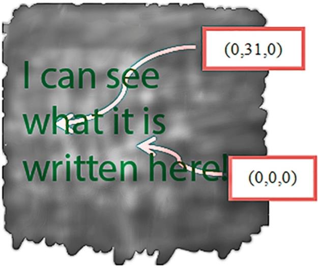
FIGURE 7 The condition to be met for the characters to be recognized by the human eye.
A reasonable assumption that is made from the start is that characters that would not be perceived by the human eye are not expected to be recognized by a machine using OCR, but every character perceive by the human eye must also be recognized by a machine (assuming there is no noise), or at least expect to be recognized. Thus, for the text that could not be perceived by the human eye, the performances of OCR are not improved by filtering first the text image using Highlight filter.
The core of the algorithm is described in the following. Since an example makes the general case more explicit, let’s bring into discussion the Blue component of the pixel having the coordinates (x,y) relative to the upper-left corner of the image.
If the absolute difference between the value of the Blue component of the pixel with coordinates (x − 1,y − 1) and the value of the Blue component of the pixel having the coordinates (x,y) is greater than 15 and the absolute difference between the value of the Blue component of the pixel with coordinates (x − 2,y − 2) and the value of the Blue component of the pixel with coordinates (x − 1,y − 1) is also greater than 15 than a certain transformation will be applied to the Blue component of the pixel having the coordinates (x − 2,y − 2) (assuming x and y are greater than 2).
The requests described before is shown in Equations (6a)–(6c) and will be as well tested separately for the other two components, i.e., Red and Green of each pixel in the image, except for the pixels in the right and bottom edges of the image (those will not be filtered). This remark is valid for Equations (6a)–(6c), but as well for all the following formulas:
![]() (6a)
(6a)
![]() (6b)
(6b)
![]() (6c)
(6c)
Why 15(30/2)? Let’s assume that the text in an image has some noise around it and the transition between the color of the text and the color of the background is done through an intermediary pixel which could be called “noise pixel” which has a different color. This situation appears frequently in the real scenarios. Then, the minimum difference of 30 between the values of the color component of the background and the color component of the text is spread among three adjacent pixels (background pixel, noise pixel, and text pixel placed as the colored ones in Figure 6) with three different colors instead of just two adjacent pixels, i.e., text pixel and background pixel as in Figure 7. For instance, if the intensity of the color of the background would be (Rb,Gb,Bb) = (0,0,0), the intermediate color (noise color) would have to be at least (Rn,Gn,Bn) = (0,0,16) and the text color would have to be at least (Rt,Gt,Bt) = (0,0,32), for the condition in Equation (6c) to be fulfilled.
Because of the diagonal manner in which the pixels which contribute to the new value of the current pixels are placed, meaning that the direction of the gradient is a diagonal direction, all the noise around curve edges that follow this direction is eliminated. Noise around vertical and horizontal edges, which form an angle of − 45° and 45° with the diagonal direction, is as well almost eliminated. Anyway, the noise affects more the curve edges than the horizontal and vertical edges.
Figure 8 shows the visual representation of all possible cases that fulfill the condition in Equation (6c), which refers to the Blue component that will be taken as an example further on. The visual representation for the Red and Green component can be obtained in the same way.

FIGURE 8 Possible cases for the condition in Equation (6c) to be fulfilled.
Before getting to the point where a specific transformation is applied, another condition, in addition to the one described in Equation (6c), must be first met. The new condition is described in Equation (7c).
If the conditions in Equation (7c) are fulfilled, then there is a diagonal “blue” gradient. If Equations (6c) and (7c) are met, then whether transformation (3) or (4) is applied to the Blue component of the current pixel so, therefore, the contrast for the component is increased depending on the result of the comparison with 127(255/2):
![]() (7a)
(7a)
![]() (7b)
(7b)
![]() (7c)
(7c)
Figure 9 spots the two of the six possible cases shown in Figure 8, showing the visual representation of the situations when condition in Equation (7c) is met.

FIGURE 9 Possible cases for the condition in Equation (7c) to be fulfilled.
If the condition in Equation (7c) is not fulfilled, then the intensity of the Blue component will be increased or decreased depending on whether the condition in Equation (8c) described below is met or not. To be more specific, if the condition in Equation (8c) is fulfilled, the intensity of the Blue component is decreased using a transformation in Equation (3) and in the opposite case, it is increased using transformation in Equation (4). Both transformations are applied, this time, regardless of the value of the Blue component:
![]() (8a)
(8a)
![]() (8b)
(8b)
![]() (8c)
(8c)
Transformations in Equations (3) and (4) are applied to the value of each component, i.e., value variable and the result depends on the contrast scale, i.e., contrast variable.
Figure 10 spots the two of the four left possible cases shown in Figure 8 (the first two of them were already discussed and matched with the condition in Equation (7c). More exactly, Figure 10 shows the visual representation of the cases which fulfill the condition in Equation (8c).

FIGURE 10 Possible cases for the condition in Equation (8c) to be fulfilled.
In case the condition in Equation (8c) is not fulfilled, the two left cases that were not discussed before, out of six spotted in Figure 8, are shown in Figure 11.

FIGURE 11 Possible cases while condition in Equation (8c) is not fulfilled.
It was not said before what happens if the condition (6c) is not met and this will be the appropriate time to be speaking about this. Well, if the condition is not fulfilled, another condition is being tested as shown in Equation (9c).
![]() (9a)
(9a)
![]() (9b)
(9b)
![]() (9c)
(9c)
If neither (9c) is fulfilled, no transformation will be applied to the Blue component of the pixel with coordinates (x − 2,y − 2). If Equation (9c) is met, the condition in Equation (8c) will be tested again. The visual representation of the cases that meet the condition in Equation (9c) is shown in Figure 12.
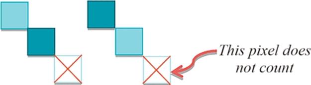
FIGURE 12 Possible cases for the condition in Equation (9c) to be fulfilled.
3.3 Visual Results of Applying Highlight Filter on Images
Highlight image filter produces the results in Figure 13. It can be seen how this filter detects the edges of the characters and sharpens them (the best example would be “ALL CHANNELS” image) and how it creates contrasting shadows behind the characters (the black shadows can be best seen on white colored “Golf: Women’s British Open” text in the image).

FIGURE 13 The visual effect of Highlight image filter.
Because of the shadows behind the sharpened edges of the characters and because of the increased contrast of the edges, the characters appear to be highlighted in the filtered image (a slightly 3D effect), which is the main visual effect of Highlight image filter.
3.4 Highlight Image Filter Program Code and Visual Representation
Part of the C# code that corresponds to Highlight image filter is being listed in Code 1. The buffer array stores the image representation, more exactly the Blue, Green, Red, and Alpha components in this order for the first pixel, then the components for the second pixel in the same order and so on for the rest of the pixels in the image.
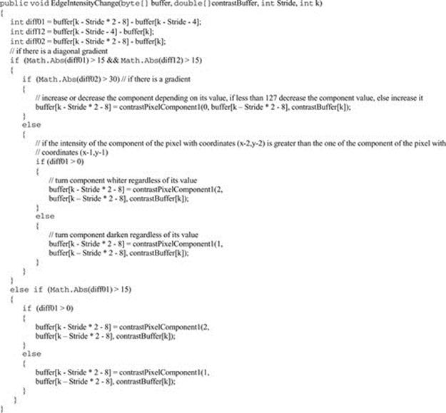
CODE 1 Part of Highlight image filter’s algorithm.
The visual representation of the algorithm is shown in Figure 14. The six cases next to the first if are the visual representation of the condition. In other words, if the condition in Equation (6c) is met, we will found ourselves in one of the six possible cases. So far for the rest of Figure 14, the possible cases that meet the conditions are shown next to the if-s and else-s, as it is also in the case of the second if, for which its condition is represented visually by two out of six possible cases.
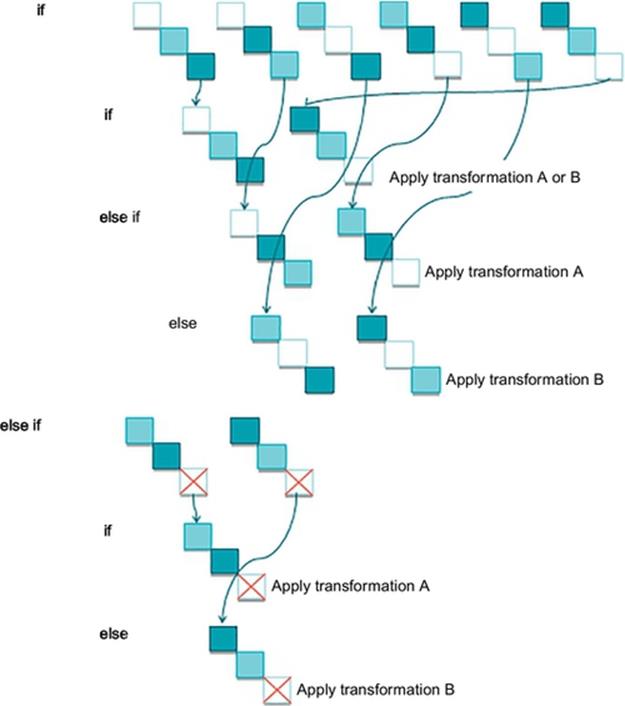
FIGURE 14 The visual representation of Highlight image filter’s algorithm.
4 Description of the optimized implementation of smart contrast and highlight Using “Byte Buffer” Techniques
The byte buffer stores byte representation of the image, namely, Blue, Green, Red, and Alpha components in this order for each pixel as in Figure 15. An additional buffer is required for filters such as Sharpen or Blur to avoid altering the original pixels, since the new value of the current pixel depends on its neighboring pixels for these filters.
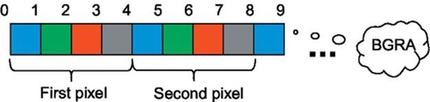
FIGURE 15 Image representation storage in the byte buffer that keeps each pixel's four components.
First step in the optimization algorithm is to obtain an object of type BitmapData (more details about this predefined class and the next ones can be found from Refs. [4,5] Web site) using LockBits method of Bitmap C# class. In next step, Scan0 property is accessed on the obtained object in order to get the address of the first pixel in the image. Once we have this address, all the image data from it are copied to the byte buffer using the overloaded Copy method of Marshal C# class. The third step is different from a filter to another and represents the calculations done on the byte buffer in order to filter the image. Finally, the byte buffer will contain the byte representation of the filtered image. By using the buffer, we avoid calling SetPixel method on a Bitmap object each time the pixels needs to be set to the filtered value, which would be time consuming since the Bitmap object is accessed as many times as the number of pixels in the image. The next step is to copy the filtered buffer back to the address of the first pixel of the image using the overloaded Copymethod. The last step is to unlock the Bitmap object, using UnlockBits method.
This optimization can be applied to any filter since it focuses on reducing the execution time related to image processing, not to the filter’s action. The average speedup using this optimization technique is 22 times considering filters such as Smart Contrast, Highlight, Sharpen, Blur, Invert and Color.
5 Conclusions
Smart Contrast is proved to be very useful especially in edge cases, which occur actually very often, such as when the color of the characters in a text image is close to the color of the background, but nevertheless would do a great work whenever a contrast increase is desired.
I recommend the usage of Highlight filter rather than other filters in situations when the image contains areas of narrow text (but sure one can also successfully use it when the text in the image is wide). After applying this filter in the situation mentioned above, the success rate of OCR on the filtered image is considerably increased.
Probably, the most important thing to mention regarding Highlight image filter is that it eliminates the noise in the image, more exactly, it focuses on eliminating the noise located all around the edges of characters in the text image by covering the isolated noise pixels with a uniform contrasting colored area around the contour of the characters that forms the shadow of the text. Beside the actions (sharpen, contrast, highlight) of this filter, the diagonal gradient direction also contributes to removing the noise from the filtered image. The image could be also a bit blurred (not too much) and still, the OCR is improved.
In few words, Highlight filter determines outstanding OCR results on text images in which,
• Text is narrow.
• Noise is present (could be around characters).
• Any other situation (e.g., lack of contrast, too much blurring).
The effect of Highlight image filter is detecting the edges and once detected it sharpens them. As well, this filter increases the contrast in a selective manner, more exactly especially in the areas of the text image where this is the most needed (i.e., edges of the characters), saving the time that would be spent with contrasting the rest of the image. Overall, it highlights the edges.
The visual effect on characters that are present in the image would be sharpening them and increasing their contrast, creating shadows (behind them) that contrast with their color and obviously highlighting them by creating a slightly 3D effect.
As a result, Highlight filter consists of an appropriate combination of the following visual effects, which contribute together to increased performances to 98% of OCR (by first applying the filter before passing the text image to the OCR engine):
• Sharpen.
• Selective contrast.
• Highlight.
Many techniques, such as adaptive restoring of text image, have been tried [8, pp. 778-781]. Image filtering has also made an improvement in important areas, such as medicine, as described by Barber and Daft [9], but lately, improving OCR performance using filtering has become and will be a great challenge. When developing Smart Contrast, which is a nonlinear image filter, I had as a starting point the Contrast filter. Beside Smart Contrast’s incontestable performances in improving OCR, this filter was actually just the triggering point for my following creation, namely, Highlight image filter, as well nonlinear, which overcomes the challenge of performing OCR with a very high success rate on text images.
References
[1] Lindeberg T. Edge detection and ridge detection with automatic scale selection. Diva Academic Archive Int J Comput Vis. 1998;30:117–154. http://www.csc.kth.se/cvap/abstracts/cvap191.html [Accessed: 1st March 2014].
[2] Rajwade A, Rangarajan A, Benerjee A. Automated filter parameter selection using measures of noiseness. Comput Robot Vis. 2010;86–93. IEEE Xplore Digital Library. Available from: http://ieeexplore.ieee.org [Accessed: 3rd March 2014].
[3] Stirb I. Highlight image filter significantly improves optical character recognition on text images. In: Arabnia HR, ed. Proceedings of the 2014 international conference on image processing, computer vision and pattern recognition; United States of America: CSREA Press; 2014.
[4] Microsoft. ColorMatrix Class. [Online] Available from: http://msdn.microsoft.com/en-us/library/system.drawing.imaging.colormatrix(v=vs.110).aspx [Accessed: 30th July 2013]; 2014.
[5] Microsoft. Bitmap Class. [Online] Available from: http://msdn.microsoft.com/en-us/library/system.drawing.bitmap(v=vs.110).aspx [Accessed: 29th July 2014]; 2014.
[6] The GIMP Help Team. Enhanced Filters. Sharpen. [Online] Available from: http://docs.gimp.org/en/plug-in-sharpen.html. [Accessed: 1st August 2013]; 2012.
[7] Fisher R, Perkins S, Walker A, Wolfart E. Laplacian/Laplacian of Gaussian. [Online] Available from: http://homepages.inf.ed.ac.uk/rbf/HIPR2/log.htm [Accessed: 15th August 2013]; 2003.
[8] Stubberud P, Kanai J, Kalluri V. Adaptive image restoration of text images that contain touching or broken characters. 778–781. Proceedings of the third international conference on document analysis and recognition. 1995. ;vol. 2. IEEE Xplore Digital Library. Available from: http://ieeexplore.ieee.org [Accessed: 3rd September 2013].
[9] Barber JC, Daft C. Adaptive filtering for reduction of speckle in ultrasonic pulse-echo images. Ultrasonic. 1986;24:41–44.
![]() IPCV paper: Highlight Image Filter Significantly Improves OCR on Text Images
IPCV paper: Highlight Image Filter Significantly Improves OCR on Text Images
All materials on the site are licensed Creative Commons Attribution-Sharealike 3.0 Unported CC BY-SA 3.0 & GNU Free Documentation License (GFDL)
If you are the copyright holder of any material contained on our site and intend to remove it, please contact our site administrator for approval.
© 2016-2026 All site design rights belong to S.Y.A.