Emerging Trends in Image Processing, Computer Vision, and Pattern Recognition, 1st Edition (2015)
Part III. Registration, Matching, and Pattern Recognition
Chapter 35. Precision distortion correction technique based on FOV model for wide-angle cameras in automotive sector
Haijung Choi1; Jeong Goo Seo1; Dae Hyuck Park1; Eui Sun Kang2 1 SANE Co., Ltd, Seoul, Korea
2 Soongsil University, Seoul, Korea
Abstract
This chapter proposes a method for estimating a distortion center to correct the radial distortion that occurs when capturing images with a wide-angle fish-eye lens. In the field of view (FOV) distortion correction model, the error of the distortion center and center of the image increases because it does not estimate the distortion center of a lens separately. This drawback deteriorates the accuracy of distortion correction. Thus, this chapter proposes a distortion correction method using the FOV model and 2D patterns in order to increase the accuracy of the distortion center estimation of a wide-angle lens. To achieve this goal, a distortion curve generated from the FOV model is compared with a straight line, thereby setting the position of the minimum difference between the curve and the straight line as the distortion center. Through this method, the accuracy of the estimation of the center of the distortion that occurs owing the error in the alignment of center points of a lens and the imaging sensor can be improved. This was also verified through experiments.
Keywords
Index distortion center estimation
FOV model
2D pattern
190° wide-angle camera
Around View Monitor (AVM)
Surround View Monitor (SVM)
Acknowledgments
This work was supported by the Technology Innovation Program (or Technology Innovation Program, “0043358, Information Composition and Recognition System for surrounding images possible for top view and panorama view of resolving power less than 10 cm) funded By the Ministry of Trade, Industry & Energy (MI, Korea)” and “R&D Infrastructure for Green Electric Vehicle (RE-EV) through the Ministry of Trade Industry & Energy (MOTIE) and Korea Institute for Advancement of Technology (KIAT).”
1 Introduction
A driver assistance system to reduce the traffic accident rate analyzes data collected from various sensors installed in a vehicle and provides its result to the driver. Around View Monitor (AVM) system is used to prevent collision accidents during parking and driving by composing data received from more than three cameras installed around the vehicle and providing surrounding image information to driver.
In general, a passenger car is equipped with four cameras with wide-angle lenses mounted on the front, rear, left, and right sides of a vehicle to capture the maximum field of horizontal and vertical images from the surroundings. A wide-angle lens, which can capture a picture with a wide angle greater than 120° with a short focal length, generates radial distortion by which a ray of light that enters the lens farther from its center is more curved than a ray of light that enters the lens closer to its center due to the effect of a curved lens. This phenomenon often occurs in fish-eye lenses used in AVM systems, and such distortion is more severe near the edge of the image than at the center.
In order to correct the distortion of a fish-eye lens, two methods have been used: approximation of distortion functions into polynomial forms and the field of view (FOV) model, which is a geographical model based on nonlinear distortion characteristics. In the polynomial distortion model, computational complexity increases as the order of polynomials increases and the difficulty of application increases as the view angle of the fish-eye lens becomes larger. However, the FOV model is more efficient than the polynomial distortion model because its design is based on the nonlinear distortion of fish-eye lenses, although it might have additional distortion when there is an error in the location of the distortion center.
To solve this problem, this chapter proposes a method to estimate a distortion center to accurately correct the distortion that occurs in the camera image signals from an ultra-wide viewing angle greater than 190°. In particular, this chapter proposes a method to find the center point of distortion that can minimize distortion using a lattice-patterned 2D plane and the FOV distortion model to correct distortion.
The remainder of this chapter is organized as follows. In Section 2, previous studies related to distortion correction are described, whereas the proposed distortion center estimation method using 2D planes is described in Section 3. In Section 4, the experiment environment and results are discussed, and the conclusion is presented in Section 5.
2 Related research
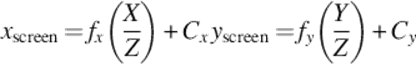
A complex calculation is required to transform 3D camera images into 2D planar images that can be processed by computers. To reduce such computational complexity, a pinhole camera model is used. A pinhole camera, which was used to locate the center point of an image, converts 3D information into 2D planar pixel units based on the optical image received through a small hole. In order to convert 3D spatial coordinates into 2D image coordinates, external parameters such as the installation height and direction of the camera, and internal parameters such as the focal length and center point of camera are required. The focal length in the internal parameter refers to a distance between the focal point and the image sensor charge coupled device (CCD) and complementary metal oxide semiconductor (CMOS), which is represented by
 (1)
(1)
Here, xscreen and yscreen refer to the coordinates on the 2D plane, whereas f is the distance between the focal point and the image plane. In addition, Z is the distance between the object and the focal point, whereas C is the displacement of the coordinate center in the projection plane. Using Equation (1), the location where the image appears on the 2D plane can be calculated. However, because only a small amount of light passes through a pinhole camera, a long exposure time is required to create an image. In order to collect a large amount of light, a curved lens is used, thereby obtaining images by collecting the curved light. When the obtained image is projected onto a 2D plane, a problem of image distortion can occur due to the characteristics of the lens. The distortion by a lens can be divided into two types: radial distortion, which is generated more severely in an area farther from the center, and tangential distortion, which creates an elliptical distortion distribution.
The typical type of lens which is installed in the vehicle is fish-eye lens and they can create radial distortion. To resolve the radial distortion problem, three methods can be employed: the method of using the center point of distortion, distortion parameters, and internal parameters; the method of performing polynomial distortion iteratively to transform the distorted curves caused by radial distortion into straight lines; and the method of using image information only. Heikkila [1] proposed a method of finding the center of distortion and internal parameters by using chessboard-like images, in which a method to find parameters that can integrate distortion correction and a camera calibration process was introduced. However, this method has a drawback that could increase iterative calculation complexity when the distortion is excessively severe, although it can be efficient when distortion is moderately severe.
In Ref. [2], three orthogonal planar patterns were introduced to cover an entire 180° image with a specific pattern of asymmetrical distortion. This method locates a vanishing point where distorted curves converge to a single point and then defines that as the center point of distortion, thereby performing distortion restoration. This method does not depend on distortion models of parameters due to the special structure of the apparatus, and therefore, it has an advantage in that it can be applied to various lenses, although it is not appropriate for a case where radial asymmetric distortion is generated.
In Ref. [3], a center radius was defined using the center of a sphere and the position of a single distorted point. A corrected position value was then used to restore the distorted curves into straight lines. Then, new radii at all positions in the image were obtained to be applied in the FOV model. This method can be used for real-time processing because it uses low-order polynomials to change curves into straight lines, although it has a weakness in terms of accuracy compared to other existing methods.
In Ref. [4], distortion parameters based on the assumption that lines were straight prior to distortion were found using the characteristics of the pinhole camera model in order to minimize the curvature of the lines, and then, they were applied to the tangential distortion correction method.
In Ref. [5], the longest curved lines were extracted and removed from 2D images, and then the correction of the remaining curves was performed. However, this method has several drawbacks in that curve detection is performed slowly whereas the removal of the curves may not be carried out accurately owing to the use of a single fixed threshold value for curve removal. To overcome these drawbacks, a method was proposed in Ref. [6] to detect and remove the lines quickly using Hough transformation.
The FOV model, which is based on nonlinear lens distortion characteristics, corrects distortion under the assumption that the center of an image and the center of lens distortion are the same. However, in the case of cameras using lenses with special functions and a number of layers, an error of the center point might occur during the manufacturing process, thereby creating a fine center point error in the projection onto the 2D plane. Therefore, not only can distortion correction not be performed correctly, but also additional distortion of the image can occur after distortion correction. To solve this problem, a method was proposed in Ref. [7] to correct distortion after estimating a center by selecting three straight lines in the image plane to decrease computation complexity.
In addition, a method was presented in Ref. [6] to estimate the center of distortion by extracting a curve from the projected 2D image and modifying it into an undistorted straight line, thereby finding the direction in which the center of the extracted curve is changed. However, its accuracy varies depending on the number of detected lines and the existence of lines around the distortion center.
This chapter proposes an accurate distortion correction method through the estimation of the distortion center of a lens using the FOV model and 2D patterns in order to correct radial distortion.
3 Distortion center estimation method using FOV model and 2D patterns
3.1 Distortion Correction Method Considering Distortion Center Estimation
The process of distortion correction considering the distortion center is shown in Figure 1. In this chapter, a 2D planar image of a chessboard pattern was used first to correct distortion of an image from a fish-eye lens quickly. Using the distorted chessboard pattern, a distortion coefficient was estimated by applying the FOV model.
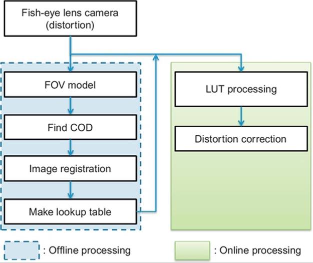
FIGURE 1 Distortion correction algorithm of 2D planar pattern.
The center of distortion was found using the estimated distortion coefficient and distorted curve component. Based on the center of distortion (Cx, Cy), a lookup table (LUT) is produced, which represents the relationship between distorted location and 2D planar location using the FOV model. Distortion can be corrected by applying the LUT produced offline to real images.
3.2 FOV Distortion Model
The FOV model [3,4] calculates a location value in the image over the plane through the coordinate in which distortion occurs when radial distortion is detected once a video image is acquired by a fish-eye lens. Figure 2 shows the FOV model.
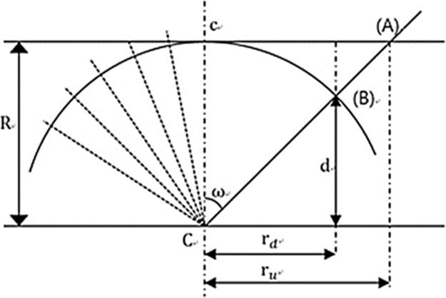
FIGURE 2 FOV model.
The distance from the center of a sphere to one point of the planar image is ru, whereas rd is the distance to the distorted location projected onto the sphere plane. Since the FOV model is based on the optical model, it is derived by trigonometric functions with regard to the angle ω. Once a point (A) is moved to a point (B) due to radial distortion projected onto the plane of the sphere and acquired by a fish-eye lens, it is projected onto the image sensor, thereby producing radial distortion. The FOV model can compute rdand ru using the distortion functions and their inverse functions.
![]() (2)
(2)
![]() (3)
(3)
The above equations are rearranged using radius R as
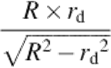 (4)
(4)
3.3 Distortion Coefficient Estimation of the FOV Model
According to the principle of the camera model [8], a straight line in 3D should be a straight line after being projected onto a 2D surface by a camera if there is no distortion. This means that the larger the difference between an actual straight-line component and a projected straight line, the larger the distortion is. Conversely, the less the difference is, the less the distortion is. The degree of camera distortion can be verified by the distortion coefficient ω of the FOV model. In the FOV model, qωi is a point of restoration of distorted point pi by the distortion coefficient ω. The distortion parameter estimation from Ref. [9] expresses a relationship of D- 1(ω, pi) with regard to the distortion coefficient, which can solve the linear equation of the least squares distance when the estimation is applied to the algorithms from p1 to pn.
By solving the equation of the i and j functions where the error function Eij(ω) is minimized with regard to the distortion coefficient ω, the distortion coefficient ω can be estimated. Using this method, distortion correction can be performed by using the distortion correction coefficient with regard to the camera distortion center.
![]() (5)
(5)
 (6)
(6)
 (7)
(7)
Using the distortion coefficient estimation method, once a chessboard pattern is captured, distortion correction can be executed quickly using only the distortion coefficient. Nonetheless, a fine error in the components of the row and column of the chessboard was discovered through experiment. In the case of an ultra-wide-angle camera, the calibration error becomes larger near the edge of the image than at the center owing to the characteristics of the lens. Thus, distortion correction using the FOV model is appropriate (Table 1).
Table 1
Measurement of Distortion Center Estimation Result in the AVM Camera
|
Codx |
Cody |
|
|
CAM #1 |
10 |
− 9 |
|
CAM #2 |
10 |
0 |
|
CAM #3 |
4 |
3 |
|
CAM #4 |
− 4 |
7 |
3.4 Distortion Center Estimation Method Using 2D Patterns
The distortion center estimation method using 2D patterns is proposed to overcome the limitation of the distortion correction method using the distortion coefficient ω of the FOV model. In this chapter, a chessboard pattern was shot to estimate the center of distortion followed by projecting it onto an actual straight line in the image data of corrected distortion, thereby estimating the center of distortion using the value of the distance difference between the straight lines.
In order to estimate the center of distortion, first the distortion in the 2D patterns was corrected using the distortion coefficient of the FOV model. Then, a certain range surrounding the center of distortion, which was determined while applying the FOV model, was set to the detection window of the center of distortion.
Next, straight lines are generated by following the detected points using the method described in Ref. [10] in the detection window of the center of distortion. Figure 3 shows the straight lines used to compute the distortion error and detection window in which the distortion center is expected. In the chessboard pattern, where a number of crossing points of straight lines can be found; crossing points of M × N representing every corner point are found, and then vertical M straight lines and horizontal N straight lines using the main outer points are generated based on the outermost points, thereby determining whether crossing points are present in the center within the straight lines. The smaller the vertical and horizontal distortions are, the closer the point is to the center of distortion, which also means it is closer to a straight line. Thus, a center of distortion can be estimated by computing the error between the straight line and the distortion. To estimate the center of distortion, distances in the row and column directions are added, and an equation for the straight line that is closest to the center of distortion and Cx,Cy is solved. Therefore, the distances to the distortion points ![]() , where there are error points with the straight line
, where there are error points with the straight line ![]() are computed.
are computed.
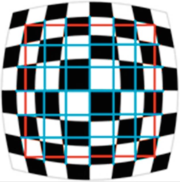
FIGURE 3 Example of the detection window of the distortion center and straight-line components.
Figure 4 shows an example of errors between the distortion and a straight line, which represents distances dn between the blue-colored straight line and the distortion in the 2D chessboard pattern. The points detected in the figure are used to determine the degree of distortion. That is, the distances between the crossing points and the straight line are computed in the vertical and horizontal directions, thereby summing the distances of the inner points (d1+ ![]() + dn) to calculate the distortion error.
+ dn) to calculate the distortion error.
 (8)
(8)
 (9)
(9)
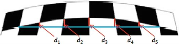
FIGURE 4 Distortion error.
In other words, it finds the minimum sum-of-squares difference between the actual straight-line component and the projected line component. By using this function for distance computation, the minimum distance to the straight-line component of row (m) and column (n) is calculated to estimate the distortion center (cx, cy).
The distortion center estimation method using 2D patterns performs precise distortion correction by finding the minimum distortion distance. Precise distortion correction can be achieved by applying the least distortion distance estimation method to the FOV distortion correction model using 2D patterns. An LUT is produced with regard to the distortion locations on the 2D plane using the estimated distortion center, thereby being applied to the actual image.
4 Experiment and evaluation
In order to verify the result of the distortion correction algorithm, the following distortion correction experiment device was developed. The experiment environment was configured using notebook computers, USB cameras, wide-angle lenses, and chessboard patterns as the hardware configuration. The target image was a 2D black and white chessboard pattern with 6 horizontal rows and 11 vertical columns. One square of the chessboard was 163pixel × 163pixel while the actual size was 45 mm2.
As shown in Figure 5, the experimental environment was prepared to perform real-time processing for the proposed algorithm, in which a 2D chessboard was positioned at the center and a real-time camera image taken with a wide-angle lens was sent to the personal computer for distortion correction.
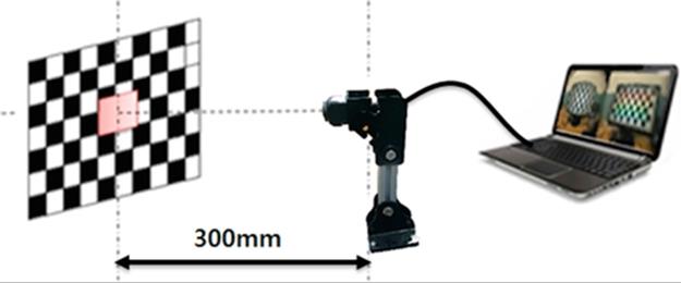
FIGURE 5 Experiment environment for distortion correction using wide-angle lens camera.
Once the accurate distortion center (C) is set in the FOV model and the distortion is corrected, all straight lines can be restored almost completely as shown in Figure 6. This result is obtained because the distortion center was set repeatedly in the distortion correction process.
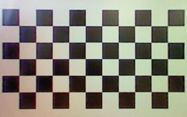
FIGURE 6 Distortion correction using the FOV model.
However, additional distortion was generated as shown in Figure 7 when distortion correction was performed again assuming that the distortion center was the center point of the image where there was an error from the lens distortion center. The analysis result of the distortion center showed that when a fine error of − 30 pixels in the X direction and + 30 pixels in the Y direction was applied to the same image, a phenomenon representing a fine curve with a specific directivity was found. This means that more severe distortion was found in proportion to the distortion center. The reason for this fine center error while projecting it onto the 2D plane is due to a mismatch of the center point with regard to the optical axis occurred during the camera manufacturing process in the case of cameras with a number of layered lenses. Therefore, while applying the FOV model, which does not estimate the center of distortion separately, there is a problem of deterioration of distortion correction accuracy as the error of the distortion center of the lens and the center point of the image becomes larger.
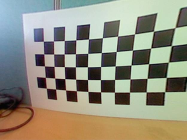
FIGURE 7 Result of the distortion center error (X axis: − 30 pixels, Y axis: + 30 pixels).
The experiment to determine the error of the measurement angle using the Zhang algorithm [11], which is regarded as a representative method of distortion correction, produced four measurement results as shown in Table 2. In addition, it was verified that deflection of the lens center was discovered in the X direction, to the right of the Y axis, and in upper portion of the image.
Table 2
Estimation Result of Distortion Center Using the Zhang Algorithm
|
Codx |
Cody |
|
|
First measurement |
12.1 |
− 1.13 |
|
Second measurement |
12.03 |
− 1.01 |
|
Third measurement |
6.96 |
− 1.87 |
|
Fourth measurement |
10.43 |
− 0.78 |
Accordingly, this chapter solved the problems that straight lines were expressed as curves due to no estimation of the distortion center in the FOV model and deflected representation by means of precise correction of the distortion center. Figures 8 and 9 show the correction result after the distortion center in the FOV model was estimated in the horizontal and vertical directions.
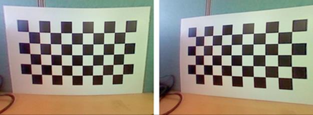
FIGURE 8 Estimation of the distortion center in the (a) vertical and (b) horizontal directions using the FOV model.
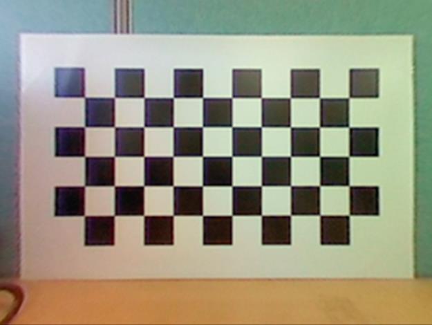
FIGURE 9 Correction result using the distortion center estimation method.
In the case of incorrect distortion correction due to the displaced distortion center, the image was corrected only in either the vertical or horizontal direction as shown in Figure 8(a) and (b), respectively. This phenomenon occurred because of the incorrect designation of the distortion center axis for the distortion correction. To minimize this error, the precise center axis can be found using the distortion center estimation method by means of 2D patterns such as a chessboard pattern. This resulted in minimizing the distortion correction error that might occur owing to instrument error while configuring the experiment or camera mounting (Table 3).
Table 3
Result of the Proposed Distortion Estimation Method
|
Codx |
Cody |
|
|
First measurement |
10 |
− 11 |
Figure 10 shows the distortion correction results as image data were received in real time from the 190° wide-angle camera. As shown in Figure 11(a), distorted correction can be found in the distorted monitor image in the horizontal and vertical directions. Figure 11(b) shows the distorted result image when the original image was corrected while (c) and (d) show the full unwrapped images of (b). If images collected from a wide-angle lens are corrected in a distorted manner, they are transformed into images of infinite size so that cropping at an appropriate scale should be used to produce images for monitoring and composition.
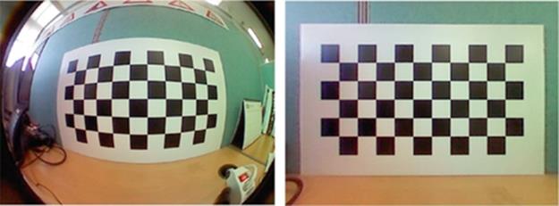
FIGURE 10 Result of the distortion center correction using 2D planar patterns.
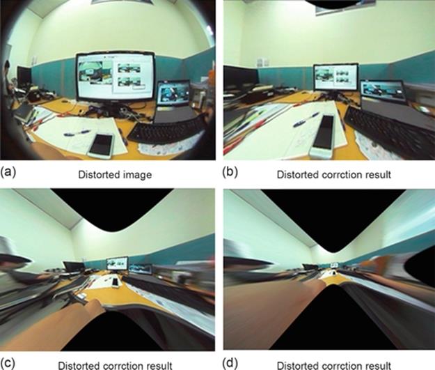
FIGURE 11 Experiment result using actual image. (a) Distorted image, (b) distorted correction result, (c) distorted correction result, (d) distorted correction result.
As shown in Figure 12, there was a significant difference in the image interface matching before and after the distortion center estimation application. The distortion center estimation can be more influential on the composition of a number of camera inputs than on a single camera input.
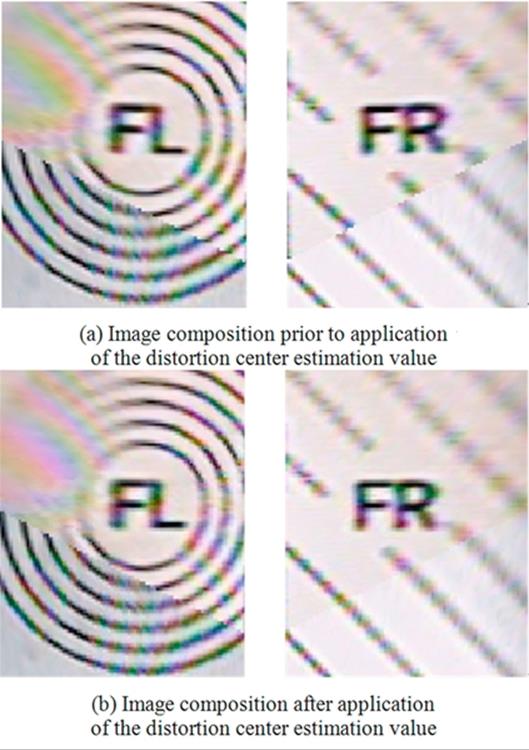
FIGURE 12 Comparison between image compositions before and after distortion center estimation. (a) Image composition prior to application of the distortion center estimation value, (b) image composition after application of the distortion center estimation value.
5 Application of algorithm to products improving vehicle convenience
We study on products which provide us with safety and convenience of vehicle. This algorithm can be applied in a way that wide-angle camera can be used to recognize danger information at the place where clear view is not secured for the driver. It can be applied to the rear view camera and SVM system.
5.1 Rear View Camera
The algorithm is used for rear view camera to correct the distortion in one channel image. It is very important algorithm for rear view camera whose angle is linked to the steering angle as giving driving direction in accordance with steering angle.
In the screen having wide angle of 190°, the information on steering angle is received using the CAN signal and driving direction is expressed in a way that it is laid over the corrected image. If distortion correction is not done precisely, there happens error in driving direction of vehicle. In addition, inconsistent errors can be occurred in accordance with steering angle. To solve these problems, this algorithm is very important. Figure 13 shows resulting image where FOV distortion correction algorithm and steering angle overlay are applied.
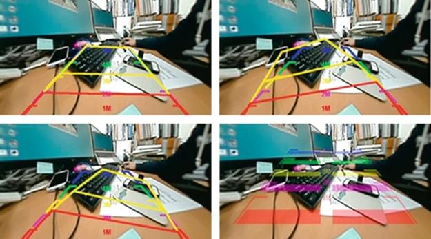
FIGURE 13 Screen of overlay in which the steering angle control is applied to the wide-angle compensation algorithm.
5.2 Surround View Monitoring (SVM) System
This algorithm is indispensable for SVM system of vehicle. This study was started to develop own SVM system and this algorithm made the SVM technology to complete.
This is a device for safer and more convenient driving as receiving four wide-angle images from front, rear, left, and right sides of vehicle to check surrounding images in the vehicle during driving or parking. SVM system is configured as Figure 14 and Freescale’s i.mx6 Processor was used in this system.
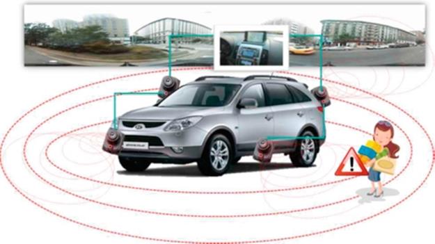
FIGURE 14 Configuration of SVM system.
SVM system gets the wide-angle camera images from four channels in analog signal and four channel images are digitalized by TW6865 and converted into data for image processing. Then, using the algorithm suggested in this chapter, the distortion correction is conducted based on the estimated center of the image. And 3D SVM is configured by texture mapping four channel images on 3D SVM model (Figure 15).
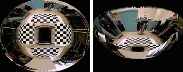
FIGURE 15 3D SVM image screen.
6 Conclusion
In recent years, vehicles have used image processing technologies increasingly while black-box systems for vehicles and AVM systems have been widely used as embedded systems for information recording, parking assistance, safe driving, and the prevention of traffic accidents. Such systems record all details of the surrounding areas using an ultra-wide-angle lens (190°) with high resolution. In order to use such images, distortion correction is necessary to enable users to monitor these images.
This chapter proposed a distortion correction method for a camera model in which the distortion center correction method was optimized using the FOV model, and distortion center was found using 2D patterns. Through the proposed method, complete distortion correction can be achieved in the vertical and horizontal directions so that images without size and pattern distortion can be used for image processing, image recognition, and monitoring by users. In general, cameras for AVM systems use high-precision center point estimation. Our algorithm can produce high quality and minimum error of AVM top views from images acquired from inexpensive cameras.
References
[1] Heikkila J. Geometirc camera calibration using circular control points. IEEE Trans Pattern Anal Mach Intell. 2000;22(19):1066–1077.
[2] Kim W, Baik YK, Lee KM. A parameter-free radial distortion correction of wide angle lenses using distorted vanishing points. In: 14th Japan-Korea Joint Workshop on Frontiers of Computer Vision (FCV); 2008:53–58 (1).
[3] Jo YK. Barrel distortion compensation of fisheye lens for automotive omnidirectional camera module system. Dongguk University; 2010 Master’s thesis of.
[4] Devernay F, Faugeras O. Straight lines have to be straight-automatic calibration and removal of distortion from scenes of structured environments. Mach Vision Appl. 2001;13(1):14–24.
[5] Thorsten T, Hellward B. Automatic line-based estimation of radial lens distortion. Integr Comput Aided Eng. 2005;12(2):177–190.
[6] Kim BK, Chung SW, Song MK, Song WJ. Correcting radial lens distortion with advanced outlier elimination. In: IEEE International Conference on Audio, Language and Image Processing (ICALIP); 2010:1693–1699.
[7] Wang A, Qiu T, Shao L. A simple method of radial distortion correction with centre of distortion estimation. J Math Imaging Vision. 2009;35(3):165–172.
[8] Shah S, Aggarwal J. Intrinsic parameter calibration procedure for a (higher distortion) fisheye lens camera with distortion model and accuracy estimation. Pattern Recogn. 1996;29(11):1775–1788.
[9] Chao T-w. Wide-scoped top-view monitoring and image-based parking guiding, Master's Thesis; 2009.
[10] Harris C, Stephens MJ. A combined corner and edge detector. In: Alvey Vision Conference; 1988:147–152.
[11] Zhang Z. A flexible new technique for camera calibration. IEEE Trans Pattern Anal Mach Intell. 2000;22(11):1330–1334.
All materials on the site are licensed Creative Commons Attribution-Sharealike 3.0 Unported CC BY-SA 3.0 & GNU Free Documentation License (GFDL)
If you are the copyright holder of any material contained on our site and intend to remove it, please contact our site administrator for approval.
© 2016-2026 All site design rights belong to S.Y.A.