Achieving Extreme Performance with Oracle Exadata (Oracle Press) (2011)
PART I
Features and Foundations
CHAPTER 4
Oracle Exadata Database Machine Platform Hardware Components
Earlier in the book, we described how computer platforms evolved from systems consisting of tightly integrated servers, storage, and databases to systems assembled from components provided by multiple vendors. We also described how tightly integrated hardware and database solutions from single vendors are becoming popular again now that cost and complexity of integration of these components and the trade-offs in performance are realized. Now, we’ll describe the pre-integrated system and prebalanced hardware platform that is the Oracle Exadata Database Machine product.
We’ll begin by describing how system performance is optimized in hardware and how the components come together in the packaging of the Database Machine. We’ll also take a look at how those components evolved in the Database Machine and how this evolution could affect your upgrade strategy. We’ll then describe how the Oracle Exadata Database Machine is linked to the outside world for communications and how it is connected to other devices. Last, we’ll cover high availability characteristics built into the hardware.
We do not intend to provide you with a recipe for building your own look-alike Database Machine from components in this chapter. The amount and complexity of the testing and integration of the Sun hardware and Oracle software required to deliver an Oracle Exadata Database Machine makes duplicating that effort a losing proposition. Whatever you might gain in cost savings by acquiring components separately is lost in the time and expense of testing and validating hardware and software components and in the time to delivery of a complete business solution. To make matters worse, Oracle is not able to support the Oracle Exadata Server Software for custom-built configurations. However, the information provided in this chapter should give you a fundamental understanding of how the Oracle Exadata Database Machine should be planned for, deployed, and upgraded within the technical architecture of your company or organization.
Finally, as you learned in the previous chapter, merely assembling hardware components leaves out the essential component of Exadata software, which provides unique advantages to the Database Machine.
Latency and Balance
Before we get into the specifics of the Oracle Exadata Database Machine, let’s review some computer hardware basics to better understand the impact of server and storage components in enabling optimal performance.
Great performance occurs when a system is well balanced such that it can deliver the needed volume of data residing in storage to fully use the processing power of the CPUs which, in turn, return results to the business users in time for them to make decisions. Balancing large storage volumes, speedy and powerful processors, and adequate throughput is fundamental to the design of an optimal system. Of course, selection of all of these components by your platform vendor must also include having an eye on the pricing of the components and of the overall system that is assembled. Since the evolution of key system components proceeds at different rates over time, maintaining a balanced system over that system’s lifetime presents its own set of challenges.
The Oracle Exadata Database Machine holds a reputation for delivering such a balanced system, dating from the platform’s introduction through its subsequent iterations. We’ll next explore how the components work together as an optimal system and will consider the roles of the Intel-based CPUs, memory, InfiniBand interconnect, and flash and disk storage technologies in the Database Machine.
Processor Speeds, Memory Capacity, and Storage
The concept of balanced computer systems has been well understood since the earliest computers were designed by hardware engineers. Early efforts by these engineers mandated specific custom processors, memory, and storage to form the systems. The invention of the microprocessor built upon the integrated circuit suddenly changed the speed of development and dynamics in the creation of new systems. As CPUs were supplied by a variety of competing vendors, the speed of change in this important component in a computer system escalated faster than some of the other key system components. Processors began to double in performance every 12 to 18 months, and memory capacities increased at a similar rate of change. But increases in speed of disk drives, relying on mechanical parts, occurred much more slowly. Disk capacities did increase at escalating rates, though, and so retrieving data became more problematic because of throughput limitations. To regain system balance, more disk spindles were needed to deliver data off of disk. More connections to storage over faster interconnects from the disks to memory were also needed.
So how does a system like the Oracle Exadata Database Machine deliver large data volumes from storage to the processors and eliminate time delays or latency in getting data to the CPUs? You will see in tables appearing later in this chapter that the Intel CPUs in the Oracle Exadata Database Machine have continued to advance in processing power and number of cores. Clearly, the closer data is to the CPUs in a system, the better the performance of queries and operations upon the data. Closest to the CPUs are small amounts of memory called cache. For example, Intel-based CPUs in the Oracle Exadata Database Machines contain multiple cache levels. The Level 1 cache is smaller than the Level 2 cache on a per-core basis. The smaller the cache size, the faster all of the information in the cache can be retrieved. Today’s Level 1 and Level 2 caches generally contain tens to hundreds of KB per core. Since these cache sizes are so small, they typically contain data coherency objects and the like. Where Level 3 cache is present, it can scale into a few MB and might contain some data. Main memory in the database server nodes provides much more capacity. For example, each database server node contains 96GB of memory in X2-2 nodes and 1TB of memory in X2-8 nodes. The memory is linked to the CPUs via an on-die memory controller. However, the amount of memory in an individual node or even a cluster is not enough to hold the volume of data needed in large-scale transaction and data warehousing systems by itself.
Disk storage devices are sized to hold the remaining data in an uncompressed state, a compressed state, or a combination of the two options. Individual disks have grown in size to terabytes. But as we noted previously, they are limited in delivering needed throughput. To offset that, you’ll observe that there are a large number of disks in the Database Machine. More recently, an additional storage solution delivering a higher level of performance entered the picture in the form of flash solid-state storage.
The Sun flash technology in the Oracle Exadata Database Machine that is the Exadata Smart Flash Cache scales to more than 5TB of storage in a Full Rack configuration and provides much faster throughput. It functions much like the cache in a conventional storage array, providing an important intermediate level of storage larger in capacity than memory but also providing more throughput than disk. To assure the flash will not wear out prematurely, the flash controller hardware features “wear leveling” to assure writes and erase cycles are rotated among all of the blocks in the device. (There are actually 32GB of pages on each Smart Flash Cache card for every 24GB of raw storage presented.) Even where 25TB per day are written to flash in an Exadata Storage Server cell, the design point of supporting 100,000 write and/or erase cycles will not be exceeded in a five-year period.
Given the introduction of faster components and the growing popularity of clustered databases and grid computing, another key consideration is the system interconnect throughput rate. The interconnect serves two purposes in an Oracle Exadata Database Machine. It links together database nodes forming a cluster, and it provides connections between the database server nodes and storage cells. Oracle actually began to deliver a low-level database communications protocol that supported InfiniBand prior to the delivery of the first Database Machine. A Zero-loss Zero-copy Datagram Protocol (ZDP) is used in communications between the database and the Exadata Storage Servers, and is based on the Reliable Datagram Sockets (RDS) OpenFabrics Enterprise Edition. The InfiniBand interconnect protocol uses Direct Memory Access (DMA).
Prior to the introduction of the first Database Machine, Oracle-based clusters were more commonly configured by hardware vendors and IT organizations with an Ethernet interconnect. Such Ethernet interconnects at that point in time delivered a bandwidth rate of 1 Gb per second. The InfiniBand interconnect introduced in the first Database Machine greatly improved bandwidth, supporting a rate of 20 Gb per second. The bandwidth rate was doubled to 40 Gb per second in the original Sun Oracle Database Machine with the inclusion of Sun’s InfiniBand switch technology.
So, how do these components work together when processing a typical workload?
How Hardware Components Work Together
Figure 4-1 illustrates the relative latency and capacity of the components. When the goal is optimal performance, you will want to have the most recently updated or queried data where it can be accessed again the fastest—generally first in the Level 3 cache (if present), then in memory, flash, and finally in disk storage.
For online transaction processing systems, when an insert or update of a row occurs, it is critical that recovery of committed transactions takes place if the system fails for any reason. Most systems designers view physical disk as the one part of a system that is nonvolatile, in that once a row is physically written to disk, it can be recovered. That said, where large numbers of transactions are being updated, such systems are usually configured with as much memory as possible to speed access, since the most recently updated transactions can be found in memory.
A data warehouse workload is quite different and often requires retrieval of a large number of rows that will not fit into memory. For this reason, the configuration focus turns to speed of transfer of the rows from storage (or throughput). Of course, if the same data is held in cache, memory, or flash as a result of earlier similar queries, the need to go to disk disappears. The Exadata Storage Server Software also performs query offload processing in storage, returning projected columns from selected rows through Smart Scans to further speed this processing.
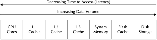
FIGURE 4-1. Server data storage hierarchy
Let’s explore a bit deeper what happens when a query occurs. Needed data typically would be looked for in the L3 cache, followed by main memory, followed by flash, and followed last by disk. The lowest level in the system where the data is found then passes it back in the other direction up the line.
Of course, all of this takes place transparently to a user of the database. A well-designed system has a database optimally “tuned” to the hardware and taking maximum advantage of these components. That is one reason why the Oracle database is able to perform optimally on the Oracle Exadata Database Machine. The ratios of the components and interconnects are well thought out and perform optimally for a variety of Oracle workloads. The database is deployed with preset initialization parameters that are aligned to the system resources available. The Exadata Storage Server Software further optimizes database performance by pushing some of the key database processing into the Exadata Storage Server cells, as described in Chapter 3.
Oracle Exadata Database Machine Packaging Basics
This brings us to the specifics of Oracle Exadata Database Machines and how the components are packaged. Let’s begin with the building blocks of the systems that are built upon standard Sun servers, the database server nodes, and Exadata Storage Server cells. Today, each database server node in the X2-2 Database Machine contains two sockets (or eight sockets in each node in the X2-8 Database Machine) and memory, as well as enough disk storage for the operating system and the Oracle database software. Table 4-1 shows the evolution of the database server nodes through 2010.
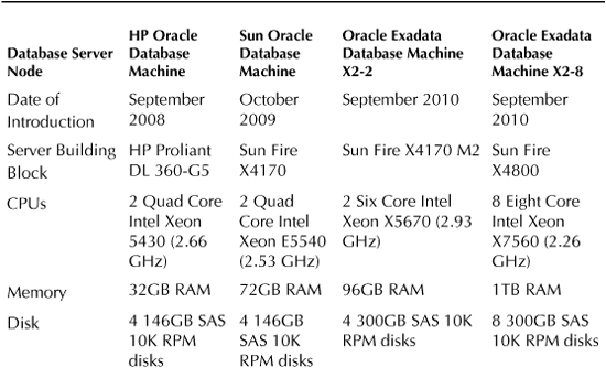
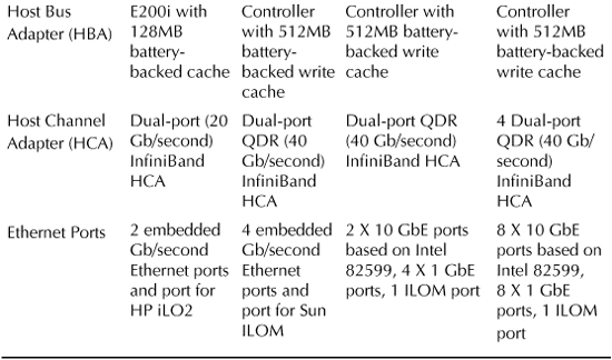
TABLE 4-1. Evolution of Database Server Nodes
Each Exadata Storage Server Cell in these configurations contains two CPUs and memory, as well as 12 disk drives and four flash cards. The Exadata Storage Server cells include CPUs and memory, also running an operating system and Exadata Storage Server Software that provides “intelligent storage” database optimization that improves overall performance of the platform. Table 4-2 shows the evolution of the Exadata Storage Server cells through 2010.
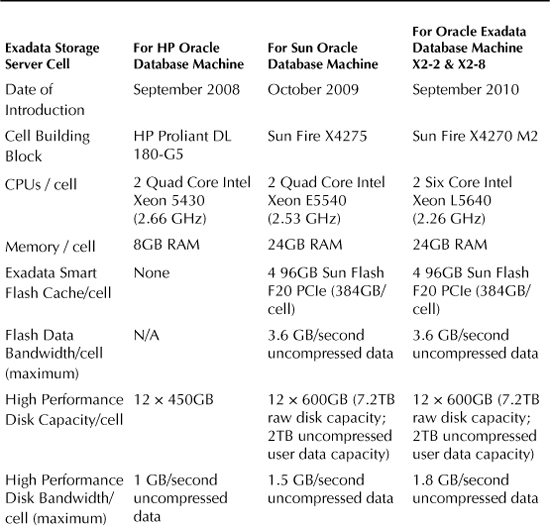
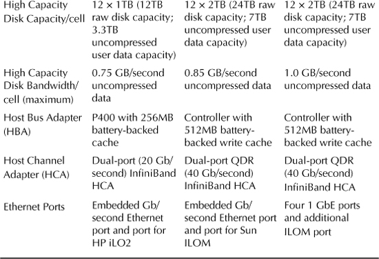
TABLE 4-2. Evolution of Exadata Storage Server Cells
A Rack contains database server nodes, Exadata Storage Server cells, InfiniBand switches, an Ethernet switch, and power. Racks come in Quarter, Half, and Full Rack configurations. Tables 4-3, 4-4, and 4-5 show the evolution of the Quarter Rack, Half Rack, and Full Rack standard configurations through 2010. Though the components within these configurations will continue to change over time (maybe by the time you read this book), there are some basics as to the packaging that should hold true for these configurations that you should understand, regardless of what version of the hardware you have.
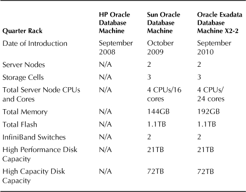
TABLE 4-3. Evolution of Database Machine Quarter Rack Configuration
Not shown in the previous tables is the Ethernet switch provided in each Rack for administration of the Database Machine. A keyboard, video display unit, and mouse (KVM) are provided for local administration with X2-2 configurations. Also included is a spares kit that includes an extra disk and extra Smart Flash Cache card for the Quarter and Half Rack or two extra disks and two extra Smart Flash Cache cards for the Full Rack, and InfiniBand cables.
Oracle has tightly defined what optimal ratios of components (such as processor cores, memory, and throughput) in database server nodes and storage cells should be. Though it is possible to activate only part of a Rack configuration, in Oracle Exadata Database Machines, Oracle recommends that you maintain the ratio of four database server nodes for every seven storage cells in X2-2 configurations if you do. That is similar to the ratio that exists in the Half and Full Racks in X2-2 configurations. For X2-2 Rack configurations where you activate just a quarter of a Full Rack, use the ratio of two database server nodes and three storage cells. The only deviation to these ratios might occur where additional storage is to be used as part of an Information Lifecycle Management (ILM) strategy for online backups and the storage is configured in a separate rack.
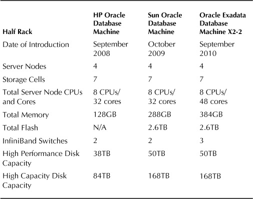
TABLE 4-4. Evolution of Database Machine Half Rack Configuration
High-Performance disks (referenced as SAS disks in early configurations) are generally selected where the goal is optimal performance, while the High-Capacity disk (referenced as SATA disks in early configurations) is selected when the goal is to provide more storage capacity in a rack. High-Performance and High-Capacity storage cannot be intermingled in the same Database Machine Rack configuration. However, separate Database Machine Racks containing High-Performance and High-Capacity disks can be linked, provided the storage in each is configured in different disk groups.
In the previous tables, we indicated disk capacity but not the amount of user data that can be stored. This amount is highly variable. Since Oracle fully mirrors the data in a standard database installation, the amount of data you can store on the available disk is immediately cut in half. You can also choose to mirror data twice for even higher levels of availability, which will result in only a third of the available disk being used for data. You should also consider that database logs, temp spaces, and other database structures will take up some space. However, the Advanced Compression Option and Hybrid Columnar Compression, described elsewhere in this book, might allow you to store far more data on this storage than the available space left after taking these factors into account.
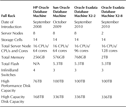
TABLE 4-5. Evolution of Database Machine Full Rack Configuration
When sizing the Database Machine, Oracle should be consulted. Disk capacity is but one sizing parameter used in selecting the size of the Rack and type of disk. Different workloads have different characteristics and demands. Oracle will sometimes use comparative sizing techniques to compare current platform characteristics to those of the Database Machine to establish a common baseline for expected performance. The fact that the Database Machine provides a balanced server, storage, and throughput configuration by design helps assure scalability for a variety of workloads.
Of course, workloads can become quite complex where the Database Machine is deployed supporting multiple Oracle databases for purposes of server and storage consolidation. Projected future workloads are often less understood. In such situations, Oracle uses predictive sizing techniques to compare the impact of potential workload variability on performance and recommend the right platform configuration.
Installation and Initial Deployment Considerations
The Oracle Exadata Database Machine is a large and heavy server. Tables 4-6, 4-7, and 4-8 outline the physical characteristics of the Database Machine Rack configurations.
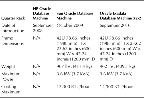
TABLE 4-6. Database Machine Quarter Rack Physical Characteristics
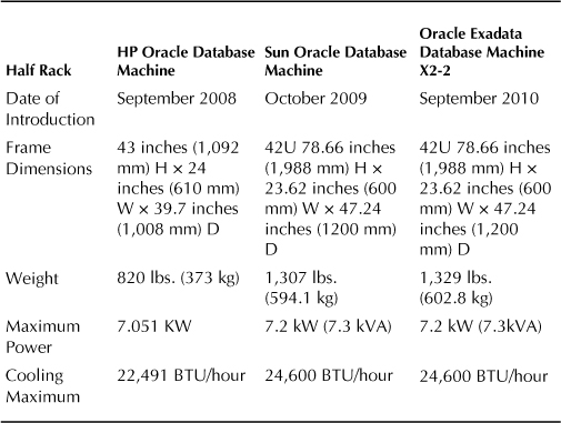
TABLE 4-7. Database Machine Half Rack Physical Characteristics
Prior to installation, Oracle works with you to assure that the Database Machine can be moved in a vertical fashion from your loading dock to the data center as part of the on-site planning process. Oracle’s Advanced Customer Services (ACS) are often additionally priced into Exadata purchases and include pre-installation planning identification of available network addresses for the InfiniBand switch, the internal Ethernet switch used for administration, and other Ethernet connections that are required. After the Database Machine is installed, ACS then configures and networks all of the servers and creates a fully mirrored default Oracle database. Performance and functionality of the installed database is then validated.
The number of network addresses needed for installation will depend on the Rack configuration. For example, the Oracle Exadata Database Machine X2-2 Full Rack InfiniBand switches require 22 addresses (one for each of eight database server nodes and 14 Exadata Storage Server cells in the Full Rack). These can be on a private subnet if the InfiniBand network is not going to be exposed outside of the Database Machine. Racks are also typically configured with two Ethernet subnets. For an Oracle Exadata Database Machine X2-2 Full Rack, 70 addresses are needed to support connections for Integrated Lights Out Management (ILOM), the KVM, other management, client/application access, and clustered servers. The ILOM connections enable monitoring of hardware generated alerts to Sun’s Ops Center showing status and remote power management, as described in Chapter 5. The ILOM alerts can also be forwarded to Enterprise Manager Grid Control via an Ops Center connector. As of the release of Exadata Storage Server Software version 11.2.1.3.1, automatic service requests (ASRs) are generated and transmitted to Oracle by an ASR manager when faults occur in database server nodes and Exadata Storage Server cells.
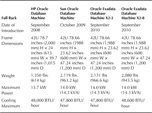
TABLE 4-8. Database Machine Full Rack Physical Characteristics
When the Database Machine is installed, air cooling should flow from the front of a Database Machine Rack to its back, where the hotter air is then exhausted. Cool air inlets consisting of perforated tiles should be placed in front of each unit. Assuming each floor tile can deliver 400 cubic feet per minute (CFM), each Quarter Rack would require one perforated floor tile, each Half Rack would require three perforated floor tiles, and each Full Rack would require four perforated floor tiles to deliver the necessary cooling.
Each X2-2 Rack, regardless of configuration, comes with two 15 kVA Power Distribution Units (PDUs), while each X2-8 Rack comes with two 24 kVA PDUs. Two PDUs are provided for redundancy purposes. For X2-2 systems shipped to the Americas, Japan, or Taiwan, low-voltage, single- or three-phase PDUs are available in the packaging. For other locations in the world, high-voltage, single- or three-phase PDUs are available for X2-2 systems. Regardless of location, there are three plugs per PDU for X2-2 Racks where the PDUs are single phase (six plugs total), and just one plug per PDU where the PDUs are three phase (two plugs total). For X2-8 Full Racks, there are two plugs per low-voltage, three-phase PDU (four plugs total) in systems shipped to the Americas, Japan, or Taiwan and also two plugs per high-voltage, three-phase PDU (four plugs total) in systems shipped to other countries.
The hardware comes with a one-year parts and labor warranty with a four-hour response time for priority 1 problems. Where 24 × 7 support is needed, Premier Support should be selected and offers 24 hours/7 days per week coverage and a two-hour response time where priority 1 problems are reported. Oracle maintains a single support line for reporting hardware and software problems. A disk retention service is offered so that failed disks that are under warranty can be replaced without returning them to Oracle, and is especially useful where data of a very sensitive nature is stored on the drives.
Some organizations require more help in order to accelerate their readiness and early implementation. Oracle offers a variety of services ranging from “Blueprint” architecture services to migration, consolidation strategy, and managed services. Many of Oracle’s partners also offer complementary and extended services, including applications and data warehousing data model implementations.
Upgrade Choices for Existing Systems
As workloads change and the business user community and data grow, you could face the need to upgrade your system. For organizations that want to grow an existing footprint, several choices exist. Within configurations that are partially full X2-2 Racks, Quarter Rack to Half Rack and Half Rack to Full Rack field upgrades are available. These upgrades to the larger configurations include the additional components necessary to match the configurations noted in Tables 4-4 and 4-5. In addition to providing additional database server nodes and Exadata Storage Server cells (or Racks containing those), upgrades include additional InfiniBand and Ethernet cables to connect the components and a spares kit. When growing beyond a Full Rack, additional Full Racks can be added by connecting them through the third “spine” switch present in the Full Racks. Up to eight Full Racks can be connected through the spine switches without the need for additional external switches. (A Half Rack may also be connected to a Full Rack or another Half Rack where a third spine switch is present.) Note that Oracle does not allow re-racking of servers and switches since there is substantial testing by Oracle behind the predefined configurations to assure better support and maintainability. However, additional storage can be put into an external rack for purposes of Information Lifecycle Management.
Where organizations anticipate a future need to rapidly add database server nodes and Exadata Storage Server cells caused by changing business conditions and want to avoid the time associated with ordering additional components and awaiting delivery, an alternative is to buy a larger standard configuration and only activate the nodes and cells initially needed (licensing the Oracle software components accordingly). As noted previously, when taking this approach, the ratio of database server nodes to Exadata Storage Server cells activated should be the same as that in a similar Half Rack or Full Rack.
As hardware ages, additional choices enter the picture. Oracle has supported the ability to connect different versions of Racks together, as illustrated where the HP Oracle Database Machine can be connected to the Oracle Exadata Database Machine using Cx4-to-QSFP cables. Newer Oracle Exadata Database Machine X2-2 components can be added to partially filled Database Machines purchased earlier as Sun Oracle Database Machines. However, some organizations might choose to use such opportunities to deploy the completely new platform for the most performance-demanding applications and recycle the older configurations for other applications as separate self-contained complexes.
Connecting to the Database Machine
Business users can communicate directly with the Database Machine via Ethernet connections to the database server nodes that contain Ethernet ports. More commonly for modern applications, the business user connects to an application server that is networked to the Database Machine. An internal Ethernet switch is provided in the Database Machine, but that switch is intended for administration purposes. For higher-speed communications and support of other devices, gateway products and media servers can be connected to the Database Machine via InfiniBand, provided there is no change made to the Oracle InfiniBand software on the Database Machine. For example, Oracle Exalogic hardware running WebLogic can be connected to the Exadata Database Machine using InfiniBand and provide load balancing and failover integration from the middle tier through a GridLink for Exadata feature in the software.
Media servers are commonly used as intermediate servers in performing tape backups. For example, Sun Fire X4275s or similar servers might serve as Oracle Secure Backup Media Servers. Two or more servers are typically configured for high availability and performance and connect the Database Machine into a wider InfiniBand QDR network. Where performance requirements are lower, media servers might be connected directly into Ethernet ports. The TCP/IP protocol is used over the network connections by Oracle Secure Backup. The media servers are also connected to a Fibre Channel SAN that is then attached to a large-scale tape backup device. One RMAN channel is set up per tape drive.
Figure 4-2 illustrates how a typical configuration might look where media servers are provided to connect the Database Machine to a tape library and applications servers are provided to link business users to the Database Machine and host the front ends of the applications. Where InfiniBand connections are shown, standard 4X QDR InfiniBand copper cables with QSFP connectors can provide connection lengths of up to five meters. InfiniBand 4X QDR optical cables can extend the distance limitation, since cables with lengths as long as up to 100 meters can be deployed.
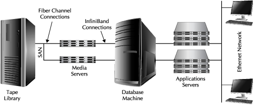
FIGURE 4-2. Typical deployment with media servers and applications servers
Highly Available Hardware Considerations
In Chapter 6, we will describe Oracle’s Maximum Availability Architecture (MAA) and strategies for deploying to it. Oracle’s MAA strategy is a mixture of hardware and software components designed to minimize planned and unplanned downtime. In this section, we’ll simply summarize some of the high-availability features included in the hardware.
Single points of hardware failure are eliminated in the standard Rack configurations. Redundant hot-swappable power supplies are built into the Database Machine database server nodes and Exadata Storage Server cells. All Racks are configured with at least two InfiniBand leaf switches, and connections are configured in a redundant fashion. Where multiple Racks are deployed with the additional spine switch, redundant connections are also provided between the spine switches. RAC assures that database server node failures are tolerated, and the Exadata Storage Server Software assures that Exadata Storage Server cell failures are tolerated. In standard installations, ASM is used to fully mirror data across storage. A minimum of three Exadata Storage Server cells are required to assure redundancy, since the Oracle Clusterware Oracle Cluster Registry (OCR) requires “voting” to manage recovery from a failure.
The storage supports bad block mapping and performance pipelining, and the disks in the database server nodes and Exadata Storage Server cells are hot-swappable. When a disk fails in an Exadata Storage Database Server cell, the database remains available and a replaced disk will rebuild itself automatically. As noted earlier, disk retention services enable Oracle to replace any failed disk without return of the failed disk to Oracle.
Database Machines can be configured in “stretch clusters” for purposes of high availability. The current distance limitation is 100 meters between Database Machines due to the InfiniBand cable length limitations mentioned previously. ASM failure groups must be created at each separate site, and Exadata storage should be added to the local failure group. A third failure group to provide “voting” disk in a quorum is deployed on shared storage such as a Network File System (NFS) filer. In Chapter 6, we will also discuss disaster recovery scenarios where Database Machines are placed at physical locations much more widely separated.
It is possible to have multiple Database Machine environments with different patch levels on the same Database Machine Rack or complex. This might be particularly desirable for deploying production, test, and development environments. Such environments must be physically partitioned and not share database server nodes or Exadata Storage Server cells.
Summary
In this chapter, we covered the basics of balanced hardware and how the components in such platforms work together to achieve optimal performance. We then discussed how Oracle Exadata Database Machine components are configured in complete rack configurations. As you have seen, the overall system is built upon leading-edge CPUs, interconnect technology, and storage that evolves over time. Oracle is closely following the evolution curve of each of these components and continually reassessing how to incorporate these components in a balanced system.
Individuals in IT organizations will sometimes ask whether they can substitute their own components within the system or otherwise modify the standard configurations. Oracle does not generally allow such changes. For example, with the exception of possibly substituting your own Ethernet switch for the administrative switch that is provided, Oracle states that any other custom components and devices must reside outside of the Oracle Exadata Database Machine. However, such policy does assure the right balance, reliability, and support that most IT organizations seek from a complete Oracle platform.
Since the focus of this chapter was the hardware platform, we said very little about the software. We certainly covered that topic in Chapters 2 and 3, and refer to it throughout the rest of the book. But clearly, the differentiation for this platform is that it is a tightly integrated Oracle hardware and software solution. That makes it a unique offering compared to other Oracle database deployment options on other hardware platforms.
In a sense, what Oracle has created is a unique platform by assembling standard server, storage, interconnect, and database components. By building a system of standard components, Oracle should be able to take advantage of future breakthroughs in these components and continue to deliver the highest-performing complete and manageable platforms at competitive prices. In the end, you will be the true evaluator of that as you build and update your Oracle Exadata Database Machine footprint.