VMware vSphere Design Essentials (2015)
Chapter 4. Designing VMware vSphere Storage
A virtual datacenter has a number of critical mechanisms, and storage is a major part of any datacenter or design. It is the axiomatic essence of every virtual infrastructure. Without a functioning storage infrastructure, the ability for VM to write data and operate as you know it would impossible.
VMware vSphere brings many new capabilities that extend the benefits of vSphere, including a number of new, storage-related features and enhancements that also bring additional scalability and performance capabilities. This chapter focuses on storage-specific design essentials, designing vSphere storage, and design considerations with various industry inputs.
In this chapter, we will cover the following topics:
· VMware vSphere storage essentials
· Determining factors that influence vSphere storage
· Designing vSphere storage
· Configuration considerations for better vSphere storage design
· Design considerations for storage layers with industry inputs
VMware vSphere storage essentials
VMware ESXi provides storage virtualization based on the ESXi host (this logically abstracts the datacenter storage layer from VM and ESXi) whereas VM uses a virtual disk to store its OS, program files, and other data associated with its activities. A virtual disk is a small-to-big physical file that can be moved, copied, backed up, and archived effortlessly. We are permitted to configure the VM with as many virtual disks as it supports. In order to access virtual disks, a VM uses virtual SCSI controllers, such as BusLogic Parallel, LSI Logic SAS, LSI Logic Parallel, and VMware Paravirtual. These controllers are the only types of SCSI controllers that a VM can see and access.
Before we dive deep into the essentials of VMware vSphere, let's explore VMware storage terminologies. Physical servers attach directly to the storage, either internal to the server chassis or in an exterior array.
About data store and VM associations; VM is stored as a set of files in its own directory in a data store. It is a logical container, like a filesystem, that hides the specifics of each storage device and provides a uniform model to store VM files. Data stores can also be used to store VM templates, ISO images, and floppy images, which can be backed by either a VMFS or a network filesystem, based on the type of storage.
About VMFS; VMware vSphere VMFS allows multiple vSphere ESXi hosts to access the shared VM storage concurrently and enables virtualization-based distributed architecture to operate across a cluster of vSphere ESXi hosts. They provide the basis for scaling virtualization outside its limitations, and VMware vSphere supports all common storage interconnects for block-based storage, including direct-attached storage, Fiber Channel (FC), FCoE (Fiber Channel over Ethernet), and iSCSI. VMware vSphere also supports placing data stores on NAS storage, accessed via an IP network, and the following table illustrates networked storage technologies that VMware ESXi supports:
|
Technology |
Protocols |
Transfers |
Interface |
|
Fiber Channel |
FC/SCSI |
Block access of data/LUN |
FC HBA |
|
NAS |
IP/NFS |
File |
Network adapter |
|
iSCSI |
IP/SCSI |
Block access of data/LUN |
Hardware iSCSI and software iSCSI |
|
Fiber Channel over Ethernet |
FCoE/SCSI |
Block access of data/LUN |
Hardware FCoE and software FCoE |
The following table illustrates the VMware vSphere features that different types of storage support:
|
Storage Type |
BootVM |
RDM |
VM Cluster |
vMotion |
Data store |
HA and DRS |
|
Local Storage |
Yes |
No |
Yes |
No |
VMFS |
No |
|
NAS over NFS |
Yes |
No |
No |
Yes |
NFS |
Yes |
|
iSCSI |
Yes |
Yes |
Yes |
Yes |
VMFS |
Yes |
|
Fiber Channel |
Yes |
Yes |
Yes |
Yes |
VMFS |
Yes |
Now, let's explore VMware vSphere storage essentials in greater depth. The virtual disk resides on a data store that is positioned on physical storage. From the standpoint of the VM, each virtual disk appears as if it were a SCSI drive connected to a SCSI controller. Regardless of whether the actual physical storage is being read through, the storage on the ESXi host is classically transparent to the guest OS that runs on the VM; moreover, on top of virtualdisks VMware vSphere offers a contrivance called raw device mapping. It is applicable when a guest operation system inside a VM requires direct access to a storage device.
VMware vSphere storage architecture comprises three layers of abstraction that hide alterations and accomplish complexity among physical storage components:
VMware infrastructure enables world-class storage performance, functionality, and availability, without adding complexity to the user applications and guest OS.
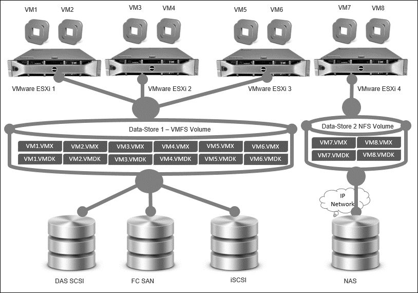
The data store provides a modest model to allocate storage space for the individual VMs without exposing them to difficulties caused by the variety of physical storage technologies available, such as iSCSI SAN, Fiber Channel SAN, DAS, and NAS.
A data store is nothing but a physical VMFS filesystem volume or a directory on a NAS. Each data store can span numerous physical storage components. As illustrated in the preceding diagram, one VMFS volume can encompass one or more LUNs from a DAS SCSI disk array on a physical machine, iSCSI SAN disk farm, or a Fiber Channel SAN disk farm. New LUNs added to any of the physical storage components are automatically discovered and made accessible to ESXi; this can be added to extend a previously created data store without powering off the ESXi servers or storage components. Conversely, if any of the LUNs within a data store are not working or have failed for some reason, only VMs that reside in the failed LUN are affected. The remaining VMs residing in other LUNs continue to work as they are.
VMFS is a clustered filesystem that can influence shared storage to permit numerous physical ESXi hosts to read and write to the same storage concurrently. VMFS provides mechanisms that can lock on a disk; it isolates it to make sure that the same VM is not switched on by multiple ESXi hosts at the same time. If a physical ESXi host fails, the on-disk lock for each VM can be released so that VMs can be restarted on other physical ESXi hosts.
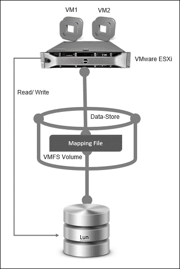
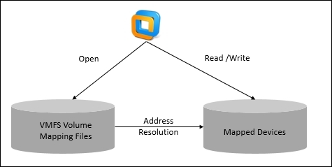
VMFS provides support for raw device mapping. Raw device mapping can be viewed as a symbolic link from a VMFS volume to a raw LUN. It makes LUNs look like files in a VMFS volume. The mapping file, not the raw LUN, is referenced in the VM.
When a LUN is opened for access, VMFS resolves the RDM file to the correct physical device and performs appropriate access checks and locking. Thereafter, reads/writes go directly to the raw LUN rather than going through the mapping file.
This is referenced in the VM configuration. Using RDMs, we can use vMotion to migrate VMs using raw LUNs, add raw LUNs to VMs using the vSphere Web Client, and use filesystem features, such as distributed file locking, permissions, and naming.
The following are the compatibility modes that are available for RDMs:
· Virtual compatibility mode permits an RDM to act accurately like a virtual disk file
· Physical compatibility mode permits direct access to the SCSI device for applications that need low-level control
Determining factors that influence vSphere storage
Over the years, people designed and built servers and paid more money for server storage. These physical servers used local direct DAS, with the infrequent raid into two node clusters, with limited performance. When businesses were in need of greater performance, they scaled out with multiple servers, or some businesses bought expensive, dedicated Fiber Channel SAN with influential array technologies. This has changed a lot with the advent of virtualization; storage is now much more than just its own capacity. Arguably, the number of terabytes that our new storage array can provide is a relatively minor interest when we are investigating requirements.
Now let's explore the factors that need to be considered, such as hard disk, performance over capacity, IOPS, and spindle considerations.
Hard disks
The following guidelines will help you in identifying the influencing factors between shared storage and local storage:
· Clustering of VMs across ESXi hosts
· Central repository that is accessible from multiple ESXi hosts
· Data replication and scalable and recoverable rollouts
· Using VMware vMotion, HA, DRS, and DPM
Performance
Performance is mostly less understood than capacity or availability but, in a virtualized infrastructure where there is substantial scope for alliance, it has a much greater influence. We can use numerous metrics—such as IOPS, throughput, and latency—to accurately measure performance.
Capacity
Capacity needs to be achieved on an ongoing basis as a business grows or shrinks, and it is generally predicted and provisioned on-demand though, unlike availability and performance, it can normally be augmented as requirements grow. It's a relatively easy procedure to add disks and enclosures to most storage arrays without experiencing downtime. So, we can normally solve capacity issues relatively easily, but it is worth considering this factor on your design.
IOPS
Workload is a crucial consideration when designing for optimal performance. Workload is characterized by IOPS, and write versus read percentages. Optimal design is usually used to determine how many IOPs you can achieve with a given number of disks. The formula behind this factor involves the Total RAW IOPS and Functional RAW IOPS.
Use the following formula to calculate Total RAW IOPS:
Total Raw IOPS = Disk IOPS * Number of disks
Use the following formula to calculate Functional IOPS:
Functional IOPS = (Raw IOPS * Write %)/( Raid Penalty) + (Raw IOPS * Read %)
The number of disks that are required to achieve a required IOPS value is the next factor that needs to be identified:
Disks Required = ((Read IOPS) + (Write IOPS*Raid Penalty))/ Disk IOPS
Spindles
Consider using SSD, which potentially removes the physical limitation of spinning media.
Cost
The budget that we want to spend will depend. It might be a large number, and we can think of it as a design constraint. As an alternative, your design needs to focus on system readiness, performance, and capacity. We must design a world-class solution with the future in mind, regardless of the expense.
Usually, the task of a decent design is to take in the necessities and provide the best solution for the lowest conceivable cost. Even if we aren't accountable for the financial aspects of the design, it's useful to have an impression of how much money is offered.
We know that the above listed factors are not comprehensive, as we are only discussing design essentials; you can add you are own factors whenever required. In the next section, let's discuss designing storage.
Designing vSphere storage
In a virtual datacenter, storage is a serious subject that is often disregarded. In a faultless business world, a virtualization project should be given unlimited cost and a clean slate to achieve what the business wants from storage. However, if we do not have a clean slate or an unlimited budget and, often, if you have been asked to use an already existing SAN, most virtual datacenters will have a SAN infrastructure implemented around a favored storage vendor's product family.
In this section, let's talk about the different types of storage available to VMware vSphere virtualization. Let's begin with FC. FC is a gold standard for both performance and connectivity, with speeds from 1 Gbps to 2 Gbps, 4 Gbps, 8 Gbps, and 16 Gbps. Initially, it was designed, as the name suggests, to use fiber optic cabling. In the past years, the standard has permitted the use of copper cabling. FC was designed to provide access to disks or storage. FC is typically implemented through a switch, a couple of switches, or director. Switches are classically smaller semimodular, less-redundant devices to support the storage infrastructure, whereas directors consist of a high port count and modular slot-based chassis, with more resilient switches, hosts, adapters, and the storage associated together to form a fabric.
Design-leveraging FC, while often complex and classy, provides high levels of readiness and performance that rely on our business requirements. This may be the best solution.
VMware ESXi supports different storage systems and arrays. The types of storage that our host supports include active-active, active-passive, and ALUA-compliant:
|
Fiber Channel Storage Array Types |
Capabilities |
|
Active-active storage system |
Features permit access to the LUNs instantaneously through all the storage ports that are accessible without important performance degradation. All the paths are active at all times, unless a path loses communication. |
|
Active-passive storage system |
Features that permit access to the system in which one storage processor is aggressively providing access to a given LUN. The other processors act as backups for the LUN and can aggressively provide access to other LUN I/Os. I/Os can be effectively sent only to an active port for a given LUN. If sending through the active storage port fails, one of the passive storage processors can be stimulated by the servers to retrieve it. |
|
Asymmetrical storage system |
Features support Asymmetric Logical Unit Access (ALUA). ALUA-complaint storage systems offer different levels of admittance per port. ALUA allows hosts to regulate the states of target ports and rank paths. The ESXi host uses some of the active paths as primary and others as secondary. |
Next, let's discuss iSCSI, which is nothing but the Internet Small Computer Systems Interface protocol. It has been used since the days before x86 virtualization. One cool VMware feature in ESXi is a software adapter that permits us to access our storage via our available NIC without having to make investments in additional NIC, if we have a limited budget. However, hardware is more effective and can provide a fabric similar to FC-leveraging dedicated Ethernet adapters or converged network adapters.
Another benefit related with iSCSI is the capability to go above and beyond traditional Ethernet networking and provide 10 GbE connectivity to vSphere infrastructures. A dedicated network for our core virtual infrastructure is a must-do. The following are some considerations to prevent issues. When using ESXi in conjunction with a SAN, we must follow specific guidelines to avoid SAN problems:
· Multiple VMFS data stores on one LUN are not recommended; hence, place only one VMFS data store on each LUN
· Never change the path policy the machine sets unless you know the inferences of making such a change
· Consider these options in the event of disaster or failure:
o Make several copies of your topology maps. Consider what happens to your SAN if any of the elements fails.
o Cross off different links, switches, HBAs and other elements to ensure we did not miss a critical loss point in our design.
iSCSI storage that our ESXi host supports includes active-active, active-passive, and ALUA compliant and its capabilities are illustrated in following table.
|
Fiber Channel Storage Array Types |
Capabilities |
|
Active-active storage system |
Features permits access to the LUNs concurrently through all the storage ports that are obtainable without noteworthy performance degradation. All the paths are active at all times, unless a path lost communication. |
|
Active-passive storage system |
Features aid the system in which one storage processor is aggressively providing permission to a given LUN. The other processors act as backup for the LUN and can be aggressively providing access to other LUN I/O. I/O can be effectively sent only to an active port for a given LUN. |
|
Asymmetrical storage system |
Features support Asymmetric Logical Unit Access. ALUA-complaint storage devices provide different levels of access per port. ALUA permits ESXi hosts to regulate the states of target ports and prioritize paths. The ESXi host uses some of the active paths as primary while others as secondary. |
|
Virtual port storage system |
Features permit access to all obtainable LUNs through one virtual port. These are active-active storage devices, but for their multiple connections through one port. ESXi multipath does not make multiple communications from a specific port to the storage. Some storage manufactures supply session managers to found and manage manifold communication to their storage. These storage systems handle port failover and communication balancing clearly. This is also called transparent failover. |
The next storage that we will discuss is FCoE. FCoE engages some of the flexibility of iSCSI with the competencies of the Fiber Channel protocol's importance-based flow control, among other competencies.
The design decision to adopt FCoE over traditional FC or iSCSI is often expected to reduce the adapters required to connect to storage and IP networks and reduce the number of cables routing from ESXi host to switches. This in turns reduces cooling costs and power consumption, and it is best to adopt the following conditions into your design:
· On the ports that communicate with an ESXi host, disable the Spanning Tree Protocol. Having the STP enabled might delay the FCoE Initialization Protocol response at the switch and cause the path failure state.
· Priority-based Flow Control should be turned on and configured to AUTO.
· Ensure that firmware such as Cisco Nexus 5000 (version 4.1(3)N2 or higher) and Brocade FCoE switch (version 6.3.1 or higher) on the FCoE switch are applied.
· If we plan to enable software FCoE adapters to work with network adapters, the following facts should be considered:
o Ensure that the newest microcode is deployed on the FCOE network adapter
o If the network adapter has multiple ports, while configuring networking add each port to a separate vSwitch; this will avoid an APD condition when a disruptive event occurs
o Never consider the option to move the network adapter port from one vSwitch to another when FCOE traffic is active
The final storage type that we will be discussing is NFS. NFS was established as a network filesystem for UNIX to permit access to network files in the same way as if they were local ones. NFS is arguably the most cost-effective and the simplest to manage. Some storage suppliers even enhance deduplication on NFS to reduce the virtual footprint.
Before NFS storage can be addressed by an ESX server, the following issues need to be addressed:
· Ensure that the virtual switch is configured for IP-based storage
· VMware ESXi hosts need to be configured to enable their own NFS clients
· The NFS storage server needs to be configured in order to export a mount point that is accessible to the ESXi host over a trusted network
The default setting for the maximum number of mount point data stores an ESX server can concurrently mount is eight. Although the limit can be increased to 64 in the latest release, if you increase the maximum NFS mounts above eight, make sure that you increase Net.TcpipHeapSize as well.
The following table will help you know which storage is accurate for your design:
|
Components to be considered |
iSCSI |
NFS |
Fiber Channel |
FCoE |
|
ESXi Boot from SAN |
Yes |
No |
Yes |
No - SW FCoE |
|
Yes - HW FCoE |
||||
|
RDM Support |
Yes |
No |
Yes |
Yes |
|
Maximum Device Size |
64 TB |
64 TB, but requires NAS vendor to support it |
64 TB |
64 TB |
|
ESXi Boot from SAN |
Yes |
No |
Yes |
No for SW FCoE |
|
Yes for HW FCoE/CAN |
||||
|
Maximum number of devices |
256 |
Default 8 to maximum 256 |
256 |
256 |
|
Protocol direct to VM |
Yes, only via guest iSCSI initiator |
Yes, only via guest NFS client |
No |
No |
|
Storage vMotion Support |
Yes |
Yes |
Yes |
Yes |
|
Storage DRS Support |
Yes |
Yes |
Yes |
Yes |
|
Storage I/O Control Support |
Yes, since vSphere 4.1 |
Yes, since vSphere 5.0 |
Yes, since vSphere 4.1 |
Yes, since vSphere 4.1 |
|
Load Balancing |
VMware PSA/MPIO |
Non-single Session |
VMware PSA/MPIO |
VMware PSA/MPIO |
|
High Availability |
VMware PSA via SATP |
NIC teaming |
VMware PSA via SATP |
VMware PSA via SATP |
|
VAAI Support |
Yes |
No |
Yes |
Yes |
|
vMSC |
Yes |
Yes |
Yes |
Yes |
|
SRM |
Yes |
Yes |
Yes |
Yes |
As you have now read about the different types of storage, let's start by designing accurate storage for our virtual infrastructure. Answering the following will provide us with the best storage for our requirements:
· Identify the storage protocol—NFS, Fiber Chancel, or iSCSI—of your choice
· Identity the mode of deployment of ESXi
· Identify the commodity servers or a converged solution
· Identify the number of HBAs we need per ESXi host
· Identify the sort of controllers and disk that will be purchased, based on what we need our storage to do
· Identify whether we have the necessary hardware redundancy for FT (necessary means having multiple CNAs, HBAs, or NICs per ESXi host, multiple paths, and connections to multiple redundant switches)
· Identify the capacity requirement for the present and future
· Identify designing for capacity, meaning RAID option considerations, VMFS capacity limits, array compression, and data deduplication.
· Identify designing for performance—in other words, measuring storage performance against requirements and calculating a disk IOPS against the VM/application requirements.
· Identify the right model storage, meaning local storage or shared storage (we'll go into this in greater detail in the following section)
· Ensure you meet the demands of integration, such as high performance, availability, and efficiency
· Make sure that you avoid using extents to grow VMFS
· Make sure that you use PVSCSI controllers whenever demanded
· Make sure that you use jumbo frames for iSCSI/NFS
· Make sure that you always isolate network storage traffic
· Make sure that you always read the vendor best practices for your array design
· Identify the point at which the total guest latency measure arrives in storage devices: KAVG (the amount of time IOPS spent on VMkernel), queue latency (the amount of time IOPS spent in HBA driver), and device latency (the amount of time IOPS spent in leaving HBA)
Storage considerations
In this section, let's explore shared storage against local storage. Shared storage, which is nothing but SAN or NAS devices, has become so common in vSphere implementation that local storage is often not considered to be an option at all. It's certainly true that each new release of VMware's vSphere products provides greater functionality for shared storage. However, local storage has its place and can offer tangible advantages. Each design is different and needs to be loomed only with focus on requirement; never dismiss local storage before you identify the real needs of your design.
Local storage versus shared storage
Local storage or DAS means the disks from which we intend to run the VMs mounted as VMFS data stores. These disks can be physically attached to the ESXi hosts. The disks can also be in a distinct enclosure connected via a SCSI cable to an external-facing SCSI card's connector. Even if outwardly mounted, it's logically still local host storage for ESXi.
Note that there are sure advantages from shared storage. The following are some points to consider as essentials against design:
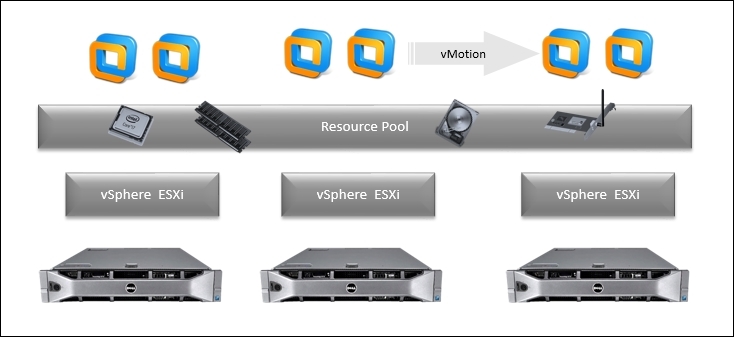
· Though there are huge enhancements in vSphere 5.1 and as shared storage is no longer an obligation for vMotion, Distributed Resource Scheduler (DRS) will not use VMs local storage.
· High-availability-enabled ESXi hosts need to have access to VMs in order to recover them when a protected ESXi host fails.
· Fault tolerance-enabled ESXi hosts need a secondary ESXi host to access the same VM so that it can step in if the primary ESXI host fails.
· If you have planned to use shared storage in your design, you can recover from host failures far more easily. If you're using local storage and a server fails for some reason, the VMs will be offline until the server can be brought online. With shared storage, even without the use of HA, we can restart the VMs on another ESXi host.
· Local storage capacity is imperfect in several respects, counting the size of the SCSI enclosures and the number of SCSI connectors and data stores.
· Using shared storage, it's possible to have a joint store for ISOs and templates. On the other hand, if you use local storage, each ESXi host needs to retain its own copy of each template.
· Using shared storage for ESXi, we can run ESXi diskless servers that can boot from SAN. This successfully makes the ESXi hosts stateless, additionally reducing implementation overheads.
· We can also use local storage for VM's swap files, which, in turn, can save more space than on shared storage for VMs. However, this method can have an effect on DRS and HA if there isn't adequate space on the destination ESXi hosts to get the migrated VMs.
· The technical blockade for deploying local storage is very low slung in comparison to the challenge of configuring a new SAN fabric or NAS devices.
· Local storage is regularly in place for the ESXi-installable OS. This means that there is regularly local space offered for VMFS data stores, or it's moderately simple to add extra disks to procure new servers.
In a nutshell, shared storage is the cornerstone of most Enterprise vSphere rollouts. Local storage originated in small business vSphere rollouts, where businesses were new to the concept or lacked the budget. To take full advantage of VMware vSphere and all it has to offer, a shared storage explanation is the comprehensible first choice. Shared storage highlights the primary goals that your design should focus on. Here are the following components that align to the PPP approach:
· Shared storage readiness generates superior redundancy and reliability and lessens failure.
· Shared storage performance means better I/O performance and scalability. Superior disk spindles, powerful controllers with large read/write cache options, and tiers of dissimilar storage disks all result in better performance.
· Shared storage capacity assembles storage, permits the use of progressive capacity-reduction knowhow, and can speech huge amounts of stowage space.
Storage DRS provides intelligent VM placement and load-balancing mechanisms based on I/O latency and storage capacity. Here are the benefits of placing storage in the SDRS mode:
· Improve service levels by guaranteeing appropriate resources to VMs
· Deploy new capacity to a cluster without service disruption
· Automatically migrate VMs during maintenance without service disruption
· Monitor and manage more infrastructure per system administrator
VMware vSphere DRS is a feature included in the vSphere Enterprise and Enterprise Plus editions.
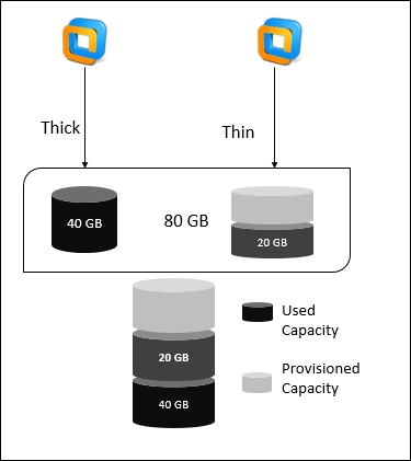
Provisioning is often overlooked. It is worth considering this option in your design. The upcoming tables illustrate three different methods; by default, ESXi offers a traditional storage provisioning method called thick provisioningfor VM. With this method, we first determine the amount of storage that VM will need for its entire life cycle existences. We then provision an immovable amount of storage space to VM well in advance.
For example, if you plan to allocate 40 GB, once this is allocated, we have the entire provisioned space committed to the VM's virtual disk. A virtual disk immediately occupies the entire provisioned space allocated to it; this is said to be thick provisioning and the latest version of ESXi also supports thin provisioning for VMs virtual disks. With the disk-level thin provisioning feature, we can create VM virtual disks in a thin format.
For a thin virtual disk, ESXi provisions the entire space required for the disk's current and future activities. Let's say, for example, that we want to allocate 40 GB. A thin disk uses only as much storage space as it needs for its initial operations. In this example, the thin-provisioned disk occupies only 20 GB of storage for its initial operations. As the disk requires more space, it can spread into its entire 40 GB allocated space:
Thin provisioning is a technique that enhances storage utilization by assigning storage space in a flexible on-demand method. Thin provisioning is different from the traditional thick provisioning. With thick provisioning, a large quantity of storage space is provided on loan in expectation of future storage needs. However, the space might remain unused causing underutilization of storage. The following table explains the difference between three methods for a quick recap:
|
Provisioning method |
Description |
|
Thick Provision Eager Zero |
In this type of provisioning, blocks are permitted and zeroed on provisioning. This is important when provisioning a fault-tolerant VM. This provisioning process takes longer as blocks are permitted and zeroed when creating the VMDK. This improves the first-time write performance. |
|
Thick Provision Lazy Zero |
In this type of provisioning, blocks are permitted upon creation but not zeroed until the VM first writes to the VMDK. This process happens quickly in comparison to an eager zero. Blocks are allocated, but space isn't used until the VM needs to write beyond the initial footprint. |
|
Thin Provisioned |
In this type of provisioning, we only use as much space as required by the initial write. We cannot convert to a thin-provisioned disk, but we can perform a storage vMotion to a thin-provisioned disk. |
Raw device mapping
Worth considering in your design is raw device mapping. An RDM is a mapping file in a separate VMFS volume that acts as a proxy for a raw physical storage device. The RDM permits a VM to straightaway access the storage device.
The RDM comprises metadata to manage and send disk access to the physical device and RDM compatibility modes are available in the following two formats:
· The virtual compatibility mode permits an RDM to act accurately like a virtual disk file, counting the use of snapshots
· The physical compatibility mode permits direct access to the SCSI device for those applications that demand lower-level control
The following illustrates the limitations of using RDM in your design:
· We are not allowed to map to a disk partition. RDMs require the mapped device to be a whole LUN.
· If you have planned to use vMotion in order to migrate VMS with RDMs, ensure that you uphold steady LUN IDs for RDMs through all the contributing ESXi hosts.
· Flash Read Cache never supports RDMs in physical compatibility mode, whereas virtual compatibility RDMs support it.
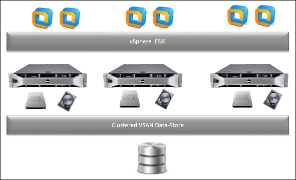
Virtual SAN
In your design, it is worth considering virtual SAN, which is nothing but a distributed layer of software that runs traditionally as a part of the ESXi host. Virtual SAN collects local or DAS disks of an ESXi host cluster and makes a single storage pool shared across all ESXi hosts of the cluster, and Virtual SAN removes the need for an external shared storage and shortens the storage formation and VM provisioning task.
vSAN virtualizes local physical storage resources assigned to ESXi hosts and converts them into resource pools of storage that can be assigned to the VM; this makes sure applications get the best out of it. Another great feature is when you make a vSAN cluster that does not require to be identical. Even ESXi hosts that have no local disks can participate and run their VMs on the Virtual SAN data store.
vSAN offers a significantly lower TCO by dropping CapEx and OpEx. Moreover, the product takes advantage of system-side hardware costs by combining interior magnetic disks and flash devices from x86 systems. Right from the start, and adding disks or nodes to their vSAN cluster as volume or performance requirements demand, organizations avoid big upfront charges. VSAN also helps organizations realize OpEx savings using automation, in turn eliminating manual procedures as well as easing usually complex change management, capacity planning tasks, and storage configuration.
The following highpoints illustrate the limitations of using vSAN on your design:
· VSAN is deployed straight into the ESXi host, and it supports only SAS HDD, SATA, and PCIe storage
· VSAN does not support storage attached through Fiber Channel, iSCSI, and USB
· VSAN does not support multiple vSAN clusters for each ESXi host, VMs with only 2 TB and not more than that
· vSAN supports features such as HA, vMotion, and DRS
· VSAN does not support features such as FT, DPM, and Storage I/O Control
· VSAN does not support SE sparse disks, SCSI reservations, RDM, VMFS, diagnostic partition, and other disk-access features
Multipathing
In order to have high availability in your design as well as to maintain constant communication between an ESXi host and storage to which it is associated, VMware ESXi supports multipathing. Multipathing is nothing but a protocol that lets us use more than one physical path to transfer data between the ESXi host and storage to which it is associated. The main purpose is that—in the event of any failure of SAN components, such as a cable, adapter, or switch—VMware ESXi can switch over to another physical path that is designed to not use the failed component. This procedure of path switching to avoid using any of the failed components is known as path failover and, as an additional feature, multipathing also provides a load-balancing mechanism. Load balancing distributes I/O loads across multiple physical paths. It should be designed in such a way that it reduces or removes probable bottlenecks.
SAN multipathing
Using SAN FC multipathing local storage topology, in your design you can use one ESXi host with two HBAs. The ESXi host communicates with a dual-port local storage system through cables. This ESXi configuration aids FT if any one of the communication elements between the ESXi host and the local storage system fails.
In SAN FC multipathing, multiple paths attach the ESXi host to the storage device, as illustrated in following diagram:
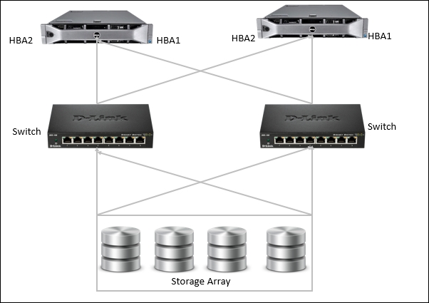
For example, if HBA1 or the link between HBA1 and the switch fails, then the network fails over to HBA2, and HBA2 provides the communication between the ESXi host and the physical switch.
From the standpoint of VMware vSphere features, SAN multipathing is categorized into two groups:
· Active-active: This array can accept I/Os from all LUNs on all of their SPs instantaneously, without degrading performance; every path is active.
· Active-passive: This array permits only one SP to accept I/O for each LUN, using other SPs for failover. SPs can be dynamic for some LUNs, while they are standbys for others. Hence, all SPs can be active instantaneously.
With active-active arrays in your design, pick the active path on a LUN-by-LUN basis; this is often said to be fixed. For active -passive arrays, the ESXi hosts determine the active path themselves; this is often described as MRU.
Native multipathing plugin
VMware vSphere's latest feature presents a redesigned storage layer. VMware says that this has a Pluggable Storage Architecture (PSA). VMware has fragmented it into two discrete modules, which are as follows:
· Storage Array Type Plugin (SATP): This is designed for path failover. The ESXi host recognizes the type of array and links the SATP based on its brand and model. The array's particulars are tartan against the ESXi host's /etc/vmware/esx.conf file, which will list all the HCL-certified storage arrays. This specifies whether the array is confidential as active-active or active-passive.
· Path Selection Plugin (PSP): This is designed for load balancing and path selection. The native PSP has three types of path policy: fixed, MRU, Round-robin. These policies are robotically nominated on a per-LUN basis based on the SATP.
NAS multipathing
NAS multipathing is essentially dissimilar to SAN multipathing in VMware vSphere, because it depends on the networking stack. IP-based redundancy and routing are used. For each NFS export mounted by the ESXi host, only one physical NIC should be considered, notwithstanding any link-aggregation techniques used to intersect many composed NICs. NIC teaming offers failover redundancy but can't load balance an export. By making multiple exports along with many associates on different subnets, we can statically load spread data store traffic.
Now, we will design another essential by creating two or more vSwitches, each with a VMkernel interface, or a single vSwitch with more VMkernel uplinks. Each uplink communicates to a separate redundant physical switch. The VMkernel interfaces and NFS interfaces are split across different subnets, as illustrated in following diagram:
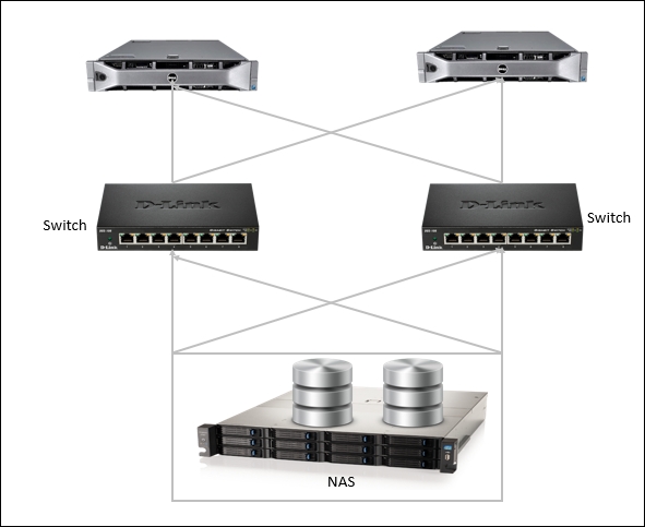
If you have considered in your design having physical switches that can cross-stack, then it is worth considering only one VMkernel interface. The NAS device requires multiple IP address targets. Plan your vSwitch with at least two NICs that are, in turn, split across the two cross-stacked switches. Ensure that VMkernel's vSwitch has its load-balancing NIC teaming policy enabled with route based on IP hash and, then, plan to combine the physical switch ports into an 802.3ad EtherChannel static option. Alternatively, if you are using a VDS, ensure that you use its dynamic LACP support to organize the EtherChannel. Also, plan to use round-robin DNS to mount the targets under different IP addresses.
Configuration considerations for better vSphere storage design
The ESXi hosts that we deploy and the amount of storage space that the VM requires regulate the level of service that we can provide in the environment and how well the environment can scale to higher service demands as the business grows. The list of factors we need to consider when building our virtual infrastructure so it scales in response to workload changes is as follows:
· Load balancing can be achieved using vMotion or VMware DRS to migrate a VM to other ESXi hosts for high availability. If you are planning to use shared storage in your design, we can design load balancing without any disruption to the business.
· Storage consolidation and simplifying storage layout helps consolidate storage resources to achieve benefits in a virtual infrastructure. We can start designing by reserving a large volume and then allowing portions to VM on demand.
· Disaster recovery is yet another option that needs to be considered when all the data is stored on a SAN. Importantly, this can enable remote storage of data backups.
In order to achieve the preceding two factors, it is worth considering the sizing option that is available from the VMware vSphere product itself. The following table illustrates the maximum configuration that should be considered on your design (never overcommit):
|
Virtual Disk |
|
|
Configuration |
Maximum |
|
Virtual Disks per ESXi host |
2,048 |
|
iSCSI Physical |
|
|
LUNs per system |
256 |
|
Qlogic 1 Gb iSCSI HBA initiator ports per ESXi host |
4 |
|
Broadcom 1 Gb iSCSI HBA initiator ports per ESXi host |
4 |
|
Broadcom 10 Gb iSCSI HBA initiator ports per ESXi host |
4 |
|
NICs that can be associated or port-bound with the software iSCSI stack per ESXi host |
8 |
|
Number of total paths on a server |
1,024 |
|
Number of paths to a LUN |
8 |
|
Qlogic iSCSI: dynamic targets per adapter port |
64 |
|
Qlogic iSCSI: static targets per adapter port |
62 |
|
Broadcom 1 Gb iSCSI HBA targets per adapter port |
641 |
|
Broadcom 10 Gb iSCSI HBA targets per adapter port |
128 |
|
Software iSCSI targets |
2,561 |
|
NAS |
|
|
NFS mounts per ESXi host |
256 |
|
Fiber Channel |
|
|
LUNs per ESXi host |
256 |
|
LUN size |
64 TB |
|
LUN ID |
255 |
|
Number of paths to a LUN |
32 |
|
Number of total paths on a server |
1,024 |
|
Number of HBAs of any type |
8 |
|
HBA ports |
16 |
|
Targets per HBA |
256 |
|
FCoE |
|
|
Software FCoE adapters |
4 |
|
Common VMFS |
|
|
Volume size |
64 |
|
Volumes per host |
256 |
|
Hosts per volume |
64 |
|
Powered on VMs per VMFS volume |
2,048 |
|
Concurrent vMotion operations per VMFS volume |
128 |
|
VMFS3 |
|
|
Raw device mapping size (virtual and physical) |
2 TB minus 512 bytes |
|
Block size |
8 MB |
|
File size (1 MB block size) |
256 GB |
|
File size (2 MB block size) |
512 GB |
|
File size (4 MB block size) |
1 TB |
|
File size (8 MB block size) |
2 TB minus 512 bytes |
|
Files per volume approximately |
30,720 |
|
VMFS5 |
|
|
Raw Device Mapping size (virtual compatibility) |
62 TB |
|
Raw Device Mapping size (physical compatibility) |
64 TB |
|
Block size |
1 MB |
|
File size |
62 TB |
|
Files per volume approximately |
130,690 |
Design considerations of storage layers with industry inputs
Design consideration for storage should start with architecting VMware storage. It should follow the life cycle, starting with gathering and developing a technical specification; estimating cost, ROI, and TCO; developing high-level design for storage implementation; and following low-level considerations, such as IOPS, RAID, interface, controllers, cache, coalescing, storage workload catalog, storage alignment, and performance fine-tuning.
While designing your infrastructure, follow the PPP approach and the following key points will assist you further in creating a better design:
· Choose a requirement-based vendor for storage. Ensure that storage vendor supports advanced vSphere features, such as VAAI and VASA, if these components are considered in your design.
· Choose a homogenous or heterogeneous server and storage platform and identify whether in your design you have placed a blade or rack server, based on the identify protocol.
· In your design, always have scalability options such as scale-out at the edge of the core.
· In your design, always have backup and disaster recovery as mandatory components; it is worth considering the option of centralized disaster tolerances.
· In your design, if you have planned to use SAN, pick the right topologies; focus on resilience and redundancy.
· In your design, consider the data flow such as congestion in the fabric, traffic versus frame congestion, and bottleneck detection.
· In your design, it's recommended that you use SIOC and Storage DRS to achieve the assignment and performance of the (monster) VMs.
· In your design, if you are using an NFS data store as a persistent scratch or log location, mount it via IP; this will avoid DNS dependency.
· In your design, choose to create LUNs with adequate space to fit a bigger VMDK (up to 2 TB); keep the option open for flexibility.
· In your design, consider Storage DRS whenever autotiring is enabled on the disk system or whenever intelligent caching solutions are used. Make sure that the I/O metric option is disabled for better performance and optimization.
· In your design, consider storage infrastructure in the light of future capacity, performance, and business continuity.
· In your design, ensure that the storage performance comprehends that the coldness to storage and RAID type cast-off can have an impression on performance.
· In your design for VMware View solutions, ensure that you accurately support the early implementation, recompose, refresh, and rebalance processes with negligible impact to ESXi hosts and the disk system.
· If you have enabled design for VM clones and snapshots, consider storage arrays that support vStorage APIs. Hardware-accelerated clones and snapshots provide greater performance and scalability.
· Always use vCenter Plugins provided by the storage vendor for NFS data store.
· For active VMware VAAI functions in your storage design, ensure that all data stores have a matching block size; this will result in faster recital and efficient operations.
· In your design, if you are using multipathing FC for storage, consider using a single-initiator for zoning.
· In your design, to obtain better Storage I/O Control, apply to all data stores to share the same physical spindles; this in turn will create a performance issue, due to assigning the same spindles.
· On your design, make sure that the data stores are in a data store cluster placed on different physical disks; this, in turn, enables I/O and the capacity to be obtainable.
Summary
In this chapter, you read about VMware vSphere storage essentials, determining factors that influence vSphere storage, how to design vSphere Storage, configuration considerations for better vSphere storage design, and design consideration for storage layers with industry inputs. In the next chapter, we will learn how to design VMware vCloud.
All materials on the site are licensed Creative Commons Attribution-Sharealike 3.0 Unported CC BY-SA 3.0 & GNU Free Documentation License (GFDL)
If you are the copyright holder of any material contained on our site and intend to remove it, please contact our site administrator for approval.
© 2016-2026 All site design rights belong to S.Y.A.