Idiot's Guides: 3D Printing (2015)
PART 3
Setting Up and Printing
Now that you’re familiar with how 3D printers work, it’s time to get into their actual operation. In this part, I go over how to set up your 3D printer’s hardware when you receive it. I also teach you how to configure your software and connect to your printer.
You also learn important things like how to level the bed and how to adjust the height of the Z axis. I then finish this part with some basic printing projects to get you started.
CHAPTER 11
Software Setup and Printer Control
In This Chapter
![]()
· The purpose of firmware and host software
· How slicing software works
· Common host control commands and useful G-code
Before you can actually print anything, you have to set up the software to slice models and control the 3D printer. There are many options for these programs, and it’s possible that your 3D printer may be restricted to one particular software package. However, the settings and setup process tend to be fairly similar between all of them.
In this chapter, you learn about your printer’s firmware, as well as how to choose host and slicing software. I then discuss how you use this software to connect to and control your printer.
Firmware Explained
Firmware is basically a program that is stored on a device. I know that sounds terribly vague, but that’s because the specifics vary quite a bit depending on the device. For example, on your computer, the operating system is not firmware, but the Basic Input/Output System (BIOS) is. On a cell phone, however, the entire cell interface may run on firmware, or the firmware could just be used to load an operating system like your computer.
The key characteristics of firmware are the following:
· It’s always the first thing to run when the device is turned on.
· It’s not stored in mass storage. Instead, it’s stored on an onboard chip that’s always present, since devices can’t function without it.
· It’s almost always set up for only one specific device.
![]()
DEFINITION
The Basic Input/Output System (BIOS) is the firmware interface used on most computers. It’s the first thing to load as soon as your computer starts up and controls how the operating system (Windows, for example) is booted.
Firmware is different from software, though in a very general way they appear similar. Think of it as being as series of layers built on top of each other: the firmware loads first and directly controls the hardware, and then the software loads and only controls the hardware indirectly via the firmware. Because the firmware controls the hardware directly, it has to be written for the specific hardware being used. This allows the software to be much more generic (and to work with a wide range of devices), because it’s not directly interfacing with the hardware.
In 3D printing, the firmware is stored on the control board and is used for the complete operation of the 3D printer. No software is needed on top of the firmware, and all of the functions of the 3D printer are controlled by the firmware running on the control board. Despite the complexity of 3D printers, the software needed to control them is still small enough to be loaded as firmware onto the read-only memory (ROM) of the control board.
Because firmware has to be small enough to fit in ROM, it’s generally written to be as small as possible. The small size combined with the base-level operation of firmware usually means it can only work with the specific hardware it was designed for. If the hardware is changed, the firmware has to be rewritten for that hardware.
In the case of 3D printers, there are many types of printers, with many types of control boards. Luckily, they’re designed similarly enough that the same basic firmware can be used for a lot of them. The firmware just has to be properly configured for the control board it’s loaded on. That configuration can be performed by the printer manufacturer or even by the user. However, other control boards—especially ones that aren’t open source—can only be loaded with firmware released by the manufacturer. If that’s the case, the user has to rely on the manufacturer to provide adequate firmware.
![]()
FASCINATING FACT
There are only a few basic firmware systems that are used for the majority of 3D printers (especially open-source 3D printers). This is possible because the hardware used for 3D printers is so similar for most models. As long as the control board is compatible, the firmware just has to be configured for the specific hardware being used.
Still, 3D printer control boards almost always have firmware that is somewhat configurable even after it has been loaded. This is so the user can adjust the settings for things like the size of the printer, how many steps it takes to move each axis 1mm, and so on. This information is stored in the electrically erasable programmable read-only memory (EEPROM) and can be changed and overwritten.
If new firmware is flashed (essentially installed) on to the control board, the data stored in the EEPROM is still kept, so the settings remain. This is good for when you’re just updating firmware, but keep in mind that if the EEPROM settings are incorrect, they will still persist. If you notice some problem doesn’t go away even after flashing new firmware, you’ll probably want to make sure it isn’t some EEPROM setting that is causing the problem.
Unless you have a problem with it, though, there is usually no reason why you need to do anything with the firmware unless you want to. Occasionally, manufacturers will release new firmware versions that either fix a bug or add a feature, but for the most part, the firmware isn’t something you need to worry about as a user.
Choosing Host Software
Unless you have an LCD controller (see Chapter 9), you need host control software to manually control the printer and run prints. The host software is what controls communication between your computer and your 3D printer.
The host software connects to the 3D printer’s control board via USB. When you start a print, the host software takes the commands generated by the slicing software and sends them over the USB connection to the 3D printer. The number of individual commands can easily number in the thousands, and each command is sent one at a time. Once the command has been performed, the 3D printer’s control board returns a confirmation to the host software, which then sends the next command. These steps are repeated over and over again until the print is finished.
Some 3D printer manufacturers require specific host software to control their printers. In most cases, however, you can choose from a variety of host software, including Repetier, Cura, ReplicatorG, and Pronterface. All of these perform the same general functions: manual control of the 3D printer, sending commands to run prints, and usually integration of slicing software. You can also modify EEPROM settings via the host software.
![]()
HOT TIP
Because each command is sent one at a time, the USB connection has to remain established throughout the entire printing process. If the USB cable is unplugged, the host software is closed, or the computer is turned off, the printing will stop and the part will be ruined. For this reason, you should make sure your computer is running throughout the entire print. More than one part has been ruined by a Windows Update restarting the computer halfway through the print.
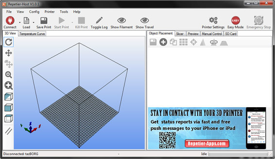
Repetier host software, with Slic3r integrated.
Choosing Slicing Software
Even if your 3D printer has an LCD controller and host software isn’t needed, you’ll still have to slice your 3D models for printing. That’s what slicing software is for: to convert your 3D models into a series of G-code commands. This is a complex task that requires a lot of processing power, so for now it’s necessary to do the slicing on a computer.
![]()
DEFINITION
G-code is the programming language that 3D printers and other computer-controlled machine tools can use for instructions. The G-code is what is used to give most 3D printers the commands they follow to produce parts. I’ll go into more detail on G-code later in this chapter.
Unlike host software, the slicing software you use can actually make a pretty big difference in how your prints turn out. This is because the slicing software is what determines how the 3D printer actually moves to create the part.
Slicers use algorithms to break down a 3D model into a series of steps for the 3D printer to follow. Those algorithms are all programmed differently, so one slicer will produce different commands than another slicer would. This can result in very different prints, depending on which slicer you choose to use. Some may produce higher-quality prints, some may print faster, and some may handle special tasks (like generating supports) better.
Because the slicing software can make such a big difference in how parts are actually printed, it can certainly be worthwhile to try multiple slicers. For example, some slicers might handle the curved surfaces of artistic models better, while others might be better suited to engineering models that have flat surfaces and require a lot of supports. You might even find that some slicers work better with your particular 3D printer than others. Experimenting with some of the popular slicers can help you find the one that suits your priorities, the 3D printer you’re using, and the kinds of models you’ll be printing.
You can find slicing software integrated with host software in the same package. Repetier and Cura are two examples of host software that include slicing software with them. However, slicing software that’s separate from host software is also available, such as KISSlicer, Simplify3D, and many others.
Connecting to Your Printer
Once you’ve chosen which host software and slicing software to use (or at least to try), you need to actually connect the host software to your 3D printer. How you do this depends on your printer, your control board, and the host software you’re using.
If you’ve purchased a printer that requires the use of proprietary software, I can’t give any real specifics on how to connect it. The good news is that 3D printer manufacturers usually choose to use proprietary software in order to make the user experience friendlier, so connecting your printer should be a simple process. The manufacturer should also provide you with instructions on how to do so.
However, if you purchased a printer with an open-source control board, there are some steps you can follow to get your 3D printer connected:
Get the proper drivers installed for your control board. The drivers give your computer the information it needs to establish a USB connection with your 3D printer. These are drivers just like you’d have to install when you connect any other new device to your computer, like a camera or an inkjet printer.
Which drivers you need to install not only depend on your operating system, but also control board you’re using. Arduino-based control boards, for example, need Arduino drivers that can be downloaded from the Arduino website (arduino.cc/en/Main/Software). Check with the manufacturer of the 3D printer or control board for the specific drivers needed for your printer.
![]()
HOT TIP
If your control board is Arduino-based, you’ll probably want to go ahead and install the complete Arduino software package. This will allow you to modify and update the firmware in the future if you choose to, along with providing the drivers needed to connect the 3D printer to the computer.
Connect a USB cable from the 3D printer’s control board to your computer. Your computer should give some indication that it sees the USB connection but shouldn’t try to install anything. If it tries to install drivers, the drivers might not have been installed properly before; go back to the first step to get your drivers in order and then try connecting again.
Open your host software and choose the COM port. Somewhere on the interface, you should see a way to change the printer setting and a button to connect the printer. In the settings, choose which COM port your 3D printer is on. This should correspond to which USB port the cable is plugged into, but there is generally no physical indication of the numbering used for the USB ports.
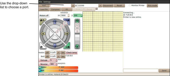
Connecting to the correct COM port using Pronterface.
You can check your device manager to determine which COM port is being used by the 3D printer, but sorting through the device manager can be difficult, as the devices aren’t always named as you might expect. Instead, it might be easier to try each of the COM ports if you don’t have a lot of devices connected via USB. If you don’t see the COM port which corresponds to the USB connection with your 3D printer, refresh the list of available COM ports.
Once you’ve found the correct COM port, it should only take a few seconds for your printer and host software to connect.
Controlling Your Printer
Once the connection between the host software and the 3D printer has been made, you can manually control the printer. Your host software should have an interface for doing this, usually called something like manual control. This is for manually sending G-code commands to the 3D printer’s control board, which then follows the command. (I’ll go over G-code more later in this chapter.)
Most host software have a few basic manual control functions, the most common of which are the following:
Jog axis: This command is used to move an axis by a set amount in a particular direction. The movement distance is usually set in increments—like .1mm, 1mm, 10mm, 50mm, and 100mm—in both the positive and negativedirections.
![]()
WATCH OUT!
If you don’t have end stops on your 3D printer, do not use the homing functions. Without end stops to tell the 3D printer when the axis is at its end point, they will keep trying to move even when they can’t physically move any further. This could potentially damage your printer.
Home axis: Homing moves the extruder, print bed, or Z axis assembly to its end point. When this function is used, the printer moves the selected axis until its end stop is triggered. Once the end stop has been triggered, the printer sets the current position for that axis to zero.
Home all: This function simply homes all of the axes with one command. Generally, it homes each axis one at a time, not all simultaneously.
Extrude: This command is for extruding a set amount of filament. You’ll generally only need to use this command when loading new filament or when calibrating your extruder.
Retract: This is the opposite of the extrude command. It runs the extruder stepper motor in reverse in order to pull the filament out of the hot end. Often, the extrude command and retract command are combined, as retraction is really just negative extrusion.
Stepper motor power: Normally, once you’ve started manually controlling the 3D printer, the stepper motors are given power. Even when they’re not moving, the stepper motors use power to hold their positions. If you want to physically move anything connected to a stepper motor, you have to turn off the power to the stepper motors, which is what this command is used for.
Hot end power: This provides the obviously necessary function of turning the hot end on and off and setting the temperature of the hot end. If you’re going to be manually extruding filament, you have to first heat up the hot end to the proper temperature.
Heated bed power: As you might expect, this turns the heated bed on and off and allows you to set its temperature. There really aren’t many reasons why you’d need to manually turn on the heated bed, but it can be useful for preheating the bed before you start a print.
Fan power: I’m not sure why you’d want to manually turn on the fan (other than to test its functionality), but if you did, you could do so using this command.
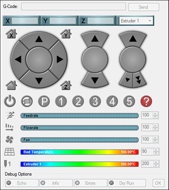
The Repetier manual control interface.
G-Code
In addition to these commands which usually have buttons, the host control software also has a way to send your own G-code commands. This is just a simple command line that allows you to send a command and receive a return (if applicable).
If you recall from earlier, G-code is what the 3D printer’s control board actually uses for instructions. It is a long series of commands that call out a particular function along with coordinates, if necessary.
The commands are very basic, and the functionality comes from stringing many commands together. Each individual command is something simple, like trace a line from point A to point B or draw an arc with a specified radius between two points. But when these simple commands number in the thousands, they can produce very complex parts.
Printing with G-Code
When you use slicing software to slice a 3D model, that software’s algorithms analyze the 3D model to determine what G-code commands it can use to reproduce the model. After the model has been sliced in thin layers, the slicer is then left with essentially a two-dimensional drawing, which it needs to trace with G-code.
![]()
HOT TIP
Technically speaking, 3D printers don’t have to use G-code. They can use other instructions, if that’s what they’re programmed to use. In fact, some 3D printer manufacturers do build 3D printers that use proprietary languages for instructions. However, that’s rare; most 3D printers today, especially in the consumer market, operate using G-code.
The software generates G-code based on rules determined by the values you set, along with the algorithms written by the programmer(s) of the software. Things like filament size, extrusion width, movement speed, and so on are all used to generate that G-code. Once a complete set of G-code instructions is generated, the G-code can then be fed to the 3D printer from the host software.
Performing Functions Manually with G-Code
Aside from when you’re actually printing, you can also send G-code commands to perform functions manually, such as changing EEPROM values, auto-leveling the bed, checking the status of the end stops, and so on.

G-code commands can be entered manually in the host software and sent directly to the 3D printer.
G-code commands have a very simple syntax; all you have to do is enter the command name (for example, M212) followed by the required values, if necessary. If you’re just requesting information, no additional values are needed most of the time. If the command allows you to enter multiple values, you can enter any combination of them. If, for instance, you were doing a homing command, you could specify if you wanted to home X, Y, Z, or any combination of the three.
There are hundreds of possible G-code commands, although not all of them will work with 3D printers (and some of them may even have different effects, depending on the particular firmware). While the vast majority of them aren’t very useful or practical to use manually, the following are a handful of them that might prove to be helpful to you:
G20 (units to inches): You can use this command to change the current units from the (generally) default millimeters to inches.
G21 (units to mm): This sets the current units to millimeters, which is generally the default.
G28 (homing): This is used to home an axis or axes. If just “G28” is entered, all three axes will be homed. However, you can enter “G28 X Z,” for example, and it will just home the X and Z axes and skip the Y axis.
G29 (auto-leveling): If your 3D printer has a probe, you can use this to auto-level the bed by probing three points. This uses the probe to measure the height of three corners of the bed in order to calculate the plane of the bed. This, in turn, can be used to raise and lower the Z height throughout the print to keep the nozzle at a constant distance from the bed.
G92 (setting coordinates): If you need to manually tell the 3D printer what its current coordinates are, you can use this command. G92 alone sets all three axes to zero. It can be appended with a number to set an axis at that coordinate without changing the others; for example, “X52.3” would set the X axis to 52.3 without changing the other axes. Any combination can be used to specify individual axes.
M92 (setting steps): If you need to change how many steps are needed per millimeter of movement—such as when you’re calibrating your printer—you can do so with this command. For example, “M92 Y200” would set the steps per millimeter to 200 on the Y axis.
M119 (end stop status): This tells you if each of the end stops is currently reading high or low, which should let you know if they’re triggered or not. You can try pushing an end stop switch with your finger when you run the command to test if the end stop is working (the state should change).
M500 (storing EEPROM values): If you have modified any of the EEPROM values (like steps per mm) using G-code commands, this command stores them permanently in the EEPROM. Be careful with this, as it’s easy to accidentally overwrite your settings with unusable values.
M503 (reading EEPROM values): This command displays all of the values currently stored in the EEPROM. The command name at the beginning of each returned value can also be used to change the particular values on that line. So if a returned line reads “M92 X200.0 Y200.0 Z802.2,” you can change any of those values by entering something like “M92 Z820.3”
While you may not ever have to actually send any manual G-code commands, it’s a good idea to become at least vaguely familiar with these in case you ever need them.
![]()
WATCH OUT!
If you were so inclined, you could technically print an entire part by manually sending G-code commands to the 3D printer. Of course, doing so would be hugely impractical, and there really wouldn’t be any point in doing so.
The Least You Need to Know
· Firmware is base-level software that runs on the control board and is stored in ROM. It’s written specifically for a particular control board and hardware setup.
· Host software is what allows your computer to connect to your 3D printer. It also sends commands to run prints.
· Slicing software generates the G-code instructions that are sent to the 3D printer by the host software. It’s often combined into a single package with the host software.
· G-code is the programming language used to issue commands to most 3D printers. This is what the slicing software generates to print parts, but you can also enter G-code commands manually to perform some useful functions.
All materials on the site are licensed Creative Commons Attribution-Sharealike 3.0 Unported CC BY-SA 3.0 & GNU Free Documentation License (GFDL)
If you are the copyright holder of any material contained on our site and intend to remove it, please contact our site administrator for approval.
© 2016-2026 All site design rights belong to S.Y.A.