Idiot's Guides: 3D Printing (2015)
PART 4
3D Modeling
Once you’ve learned how to 3D print, you’ll be eager to print all of the cool models you find online. But it won’t be long before you want to design your own models to print. In this part, I teach you how to do just that. You learn how to use CAD software to create your own models, and how to optimize them for 3D printing. You also learn about basic reverse engineering techniques, so you can print useful parts that work with existing products.
CHAPTER 15
Introduction to CAD
In This Chapter
![]()
· How CAD differs from other kinds of 3D modeling
· Common CAD modeling and sketching commands
· Why units and scale are important in CAD
Computer-aided design (CAD) is how virtually all new products are designed these days. CAD software is used to create 3D models of the parts of a product, which can be used to make every step of the development and production process more efficient. Over the past 30 years or so, CAD has literally revolutionized product design and development.
To really take full advantage of 3D printing, you’ll want to learn 3D CAD modeling. It’s not an easy skill to learn, but it’s necessary if you want to create your own designs. And learning the basics shouldn’t be too difficult. In this chapter, I take you through all you need to know about CAD for 3D printing.
Why CAD Came About
Before the introduction of CAD, developing a new design was a very slow and error-prone process. If someone had an idea for a product, the design had to be drawn by hand. Just creating the drawing introduced the possibility of mistakes, and that’s assuming the design would work. It wasn’t until the parts were actually made that the designer could know for sure whether they would even fit together, much less work.
![]()
FASCINATING FACT
Most modern professional CAD systems have add-ons for running simulations. Engineers can use these simulations to test heat transfer, stress analysis, load capabilities, and so on. With the proper use of simulations, the development process in many industries has been made significantly more efficient.
Modern CAD systems change all of that and drastically improve the process. 3D models can be created and used to test how the parts fit together. Those models can even be used in physics simulations, which can tell the engineer if the individual parts will hold up to the stresses involved, and if the assembly as a whole will work.
Once the 3D models have been created, they can be used to quickly create accurate 2D technical drawings for manufacturing. Because those drawings are based on the models, there is little risk of inaccuracy. Creating those drawings is a lot faster than drawing them by hand, and they can be automatically updated if the 3D model is revised.
In many cases, like when the parts will be 3D printed or CNC milled, the drawing isn’t even necessary. Instead, the 3D models can be sent straight to the 3D printer. This makes drawings unnecessary in the prototyping stage (although most companies still use drawings for manufacturing).
Basically, CAD has made every step of the engineering process better. But it’s not just engineers and designers who can take advantage of the benefits of CAD. As a 3D printer user, you, too, can use CAD software to create designs to print.
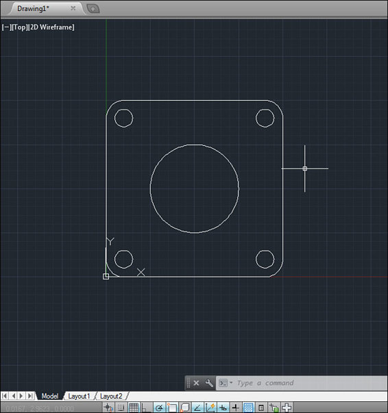
A simple flat pattern designed in 2D CAD.
Artistic 3D Modeling vs. CAD Software
Technically speaking, CAD is not synonymous with 3D modeling (though it is often improperly used that way). A great deal of CAD work is done purely in 2D, in which case it’s similar to traditional drafting by hand (just using a computer to draw instead of a pencil). And conversely, not all 3D modeling is CAD.
![]()
DEFINITION
Drafting is the process of creating technical drawings of parts and assemblies. A person who does this is a drafter (or draftsman or draughtsman). Traditionally, this was done with a pencil and paper, but it is now done almost exclusively with CAD software.
CAD is a term usually used in the context of engineering. CAD software is generally used to design functional parts and assemblies. This is in contrast to 3D modeling software that’s used to create artistic models like sculptures and characters.
So why the differentiation? It’s not just the usage that makes them unique; the software itself is vastly different as well. Because artistic 3D modeling and CAD modeling serve completely separate purposes, the respective software is optimized for those purposes.
Artistic 3D modeling software, or sculpting software, is made to make it easier for artists to do their jobs. Exact dimensions are rarely important to them; instead, they need to be able to freely form the models visually. Their goal is to create a model which is aesthetic in nature, so their 3D modeling tools reflect that.
CAD modeling, on the other hand, is all about creating models with very specific dimensions and a defined form. CAD designers don’t approach this from a visual perspective, but from a mathematical one. The aesthetics of the part being designed can certainly be important, but they still have to be specifically defined.
The differing goals between artistic and CAD 3D modeling result in a fundamental difference in the way the software works. Artistic 3D modeling software is free form and allows the artist to create and modify shapes, points, and faces without necessarily defining any parameters. The artist can just sculpt the model based on how he thinks it should look.
3D CAD software is parametric, which means that every shape is defined with specific parameters (or dimensions). Technically speaking, some shapes can be created without explicitly defining parameters, but doing so is generally considered to be bad form. And whether the user defines the parameters or not, they are still created by the software and can be modified later.
![]()
HOT TIP
If you’d prefer to use an artistic 3D modeling program instead of a CAD program, Blender is a good option. It’s also free and open source, and has a huge user base and plenty of add-ons. It’s a very high-quality program, so much so that it competes with the professional alternatives. However, it has a very steep learning curve and is difficult to learn.
The ability to modify existing parameters is probably the most important function of CAD software. Because every feature you create is defined by parameters, those parameters can be modified to change the model. Even if it’s the very first feature you create, you can still change it, even after the rest of the part has been modeled.
From a design perspective, this trait of CAD software is invaluable. You can easily adjust the dimensions of the parts as needed during the design process. Parameters can also be linked together with math formulas, so that adjusting one dimension automatically updates others. Using that functionality, you can create a single model that can be used to produce parts in a variety of sizes (for example, nuts and bolts in different sizes).
CAD Software Options
When it comes to CAD software, the best programs you’ll find are the ones made specifically for engineering. The three most popular parametric engineering CAD programs today are Solidworks, Autodesk Inventor, and Pro/Engineer (which has been renamed to Creo). These are all great programs, but because they’re meant for professional use, they’re very expensive. However, they often have student versions available, so that can be worth looking into if you’re a student.
However, if you’re not a student and don’t want to spend a small fortune on software, there are still some options available. In recent years, a number of open-source and/or free CAD programs have been released, such as FreeCAD, Tinkercad, and Autodesk 123D. These are all usable, and free is a hard price to beat, but I’ve found them to be pretty lacking in comparison to the professional options. That said, they should be adequate for hobby use, especially when you’re just getting started.
Aside from CAD applications, there are some other 3D modeling programs you may find useful. These won’t be parametric like the others, but many people still find them useful. SketchUp, Blender, and Wings 3D are some good examples you may want to try if you find the CAD workflow doesn’t work for you.
Another free (and open-source) option is OpenSCAD, which is very unique among CAD programs. The developers advertise it as “The Programmer’s Solid 3D CAD Modeler,” because you build the model by writing a script which defines the model instead of using a graphical user interface (GUI). It may sound strange, but it’s proven to be very popular with people who are comfortable with code.
![]()
HOT TIP
Try using a variety of different programs to get a feel for what each offers. Even the programs that aren’t free will usually have free trials available. This software is difficult to learn, and it’s a good idea to try different ones to determine which makes the most sense to you.
An Overview of Common CAD Program Commands
I don’t have room here to cover all of the commands used in all of the various CAD programs, but I will cover some of the more common ones. Bear in mind that the command names will vary depending on the specific software you’re using, but the basic functions of the commands will remain the same. The specific method for using the commands will also differ between programs, so I’ll really just be explaining their functions here.
I’ll break these up into two sets of commands: modeling commands and sketching commands. The modeling commands are used to add new features to the model, while the sketching commands are used to define 2D drawings to use with those features.
Modeling Commands
Extrude: This is almost definitely going to be the most common command you’ll use. Its name is derived from the extrusion manufacturing process, which might help you understand what it does. (See Chapter 3 for a refresher if you don’t.) When using this command, you sketch a 2D cross-section, which is then extruded (perpendicular to the cross-section) to form a 3D feature.
Extruded cut: In some CAD programs, this command is combined with the extrude command (you just specify that it’s a cut). This works in the same way as the extrude command, except it removes material from an existing solid body (to create a hole, for example).
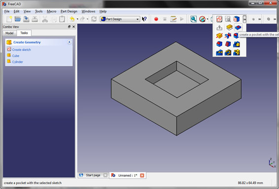
An example of the extruded cut command in a CAD program.
Revolve: This command allows you to create a feature by spinning a 2D cross-section around a central axis. You define how many degrees it will spin, and a solid body is created based on that. So, for example, to create a sphere, you could rotate a half-circle 360°.
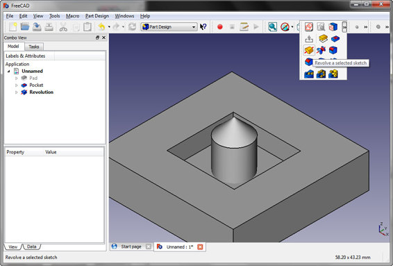
An example of the revolve command in a CAD program.
Revolved cut: Just like with the extruded cut, this command does the same thing as the revolve, except it removes material instead of adding material.
Sweep: A sweep is a little more complicated than the extrude and revolve commands. This creates a solid by taking a 2D cross-section and sweeping it along a 2D or 3D trajectory (the path). This requires a sketch for the cross-section, as well as another sketch for the trajectory. The sweep command is often used to create pipes and tubes but can be used for a variety of purposes.
Swept cut: You may be noticing a trend here. Most commands that can create a new solid also have a counterpart for removing material from an existing solid, so sweep has a counterpart in swept cut. This command has many uses, like cutting channels into a part.
Loft: This command is similar to the sweep command, except you sketch two or more cross-sections (instead of single cross-section and a path). This means the cross-sectional shape of the solid can vary along its length (for instance, from a circle to a square). If, for instance, you wanted to transition from a square tube to a round tube, you could use this command.
Lofted cut: As usual, the loft command has a material removal counterpart. If you’re familiar with a Venturi (like in a carburetor), this is the command that could be used to create such a feature.
Hole: Many CAD programs also include some kind of hole command. You could really make the same feature with the other commands, but this often simplifies the process. Often, specifications for a number of standard fasteners will be automatically loaded, allowing you to quickly create holes for those fasteners. However, the fastener threads aren’t usually physically modeled; instead, a visual representation (usually a graphic) is added along with the specifications. This means the threads made with this tool won’t be 3D printed.
Fillet: Use this command to create rounded edges. It can be used on both interior and exterior edges. It is defined based on the radius of a circle, which is tangent to both faces that intersect to make the selected edge.
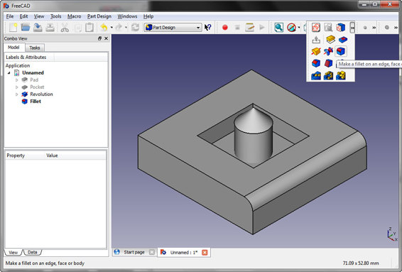
An example of the fillet command in a CAD program.
![]()
DEFINITION
In geometry, a tangent line touches a curve at a single point and continues straight on from that point. The easiest way to visualize this is to picture a circle. A tangent line touching the far-right side of the circle will continue on vertically (up, down, or both), touching just a single point of the circle. The actual mathematics of defining a tangent line are fairly complicated, but luckily the CAD software handles all of that—you only need to be concerned with the practical effect.
Chamfer: This is similar to a fillet, except it cuts the edge instead of rounding it. It’s useful for making edges less sharp without rounding them. It’s defined based on the distance it’s cut in on each face, or one distance and an angle (commonly 45°).
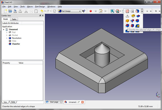
An example of the chamfer command in a CAD program.
Shell: You can use this command to make a solid body hollow. For example, you could use it to make a cube into a hollow box (with one side removed and the others given a thickness). The shell command requires that you select a face to remove and define a thickness to give to the other faces. This is very useful for creating parts like project enclosures.
Mirror: The function of this command is pretty straightforward: it allows you to take a feature and reflect it across a plane. You use this to create symmetrical features like bolt holes.
Helix/spiral: This really isn’t a modeling command on its own but is more of an intermediary. The helix command can be used to create various kinds of spiral paths, which can in turn be used to create things like springs and threads.
Plane: This is a command for creating a reference plane in 3D space. It can be used as a mirroring plane, as a plane to extrude from, or simply as a dimension reference.
Axis: Like a plane, this is used for reference. It can be used for dimensioning, as an axis for the revolve command, or for creating other references (like planes).
Point: Another reference, this one is used to create a single point in 3D space. For instance, you could create a point at the intersection of a plane and an axis. It’s useful for creating dimensions, and to use as a reference for other features.
Sketch: Most features will require a 2D sketch to define their cross-sections, and this command allows you to create that sketch. A sketch can be made on any plane; once you’ve selected a plane, you’ll have a whole new set of commands that are used specifically for drawing.
Sketching Commands
Line: The most basic of all of the sketching commands is the humble straight line. It’s pretty self-explanatory: you use it to make lines. Draw four lines in a square, and then extrude that, and you’ll have a cube.
Circle: Again, this one is pretty obvious: you use it to make circles. They can be defined in a number of ways, such as by radius, diameter, center point, tangent lines, and so on.
Ellipse: As you’d expect, this is used to draw ellipses. You specify the height and width separately as needed.
Arc: Both circles and ellipses can be trimmed to make arcs, but you can skip that extra step and draw an arc from the get-go. Just like circles and ellipses, arcs can be defined in a number of different ways that are useful in different situations (such as by their end points and radii, three points, and tangencies).
Rectangle: If you don’t want to bother drawing four lines manually, you can use this to quickly create squares and rectangles.
Polygon: To create a polygon (like a hexagon or octagon), you could manually draw it, but that would take a significant amount of time to properly define the angles and lengths of each line segment. So many CAD programs include this command to quickly create polygons with a specified number of sides.
Text: The text command is useful for engraving or embossing letters onto a face or for creating cut-out text.
Fillet: Just like you can round edges when working with the 3D model, you can also round corners when sketching. The command works in the same way by defining a radius.
Chamfer: You can also chamfer corners while sketching. Again, this works in the same way as when you’re using it on the 3D model.
![]()
DEFINITION
A chamfer is a simple beveled edge that connects two surfaces. If the surfaces meet at 90 degrees, a standard chamfer will cut across at 45 degrees for symmetry. However, a chamfer does not have to be symmetrical and can cut across at other angles as well.
Trim: This command is used to trim a line, circle, ellipse, and so on before or after an intersection (or between two intersections). This is an extremely useful tool, as it allows you to combine primitive overlapping shapes into complex cross-sections.
Extend: The opposite of the trim command. This extends a line along its current path until it intersects another line.
Offset: The offset command is used to create another line that is offset from an existing line. For example, to create a hollow tube, you could draw a circle and offset it by the thickness of the tube wall. When you extrude that, it will create your hollow tube.
Mirror: This is for mirroring lines across a mirror line. It’s very similar to the mirror feature used in the 3D modeling area.
Pattern: How exactly the pattern features work depends on the CAD software you’re using, but they all have the same goal. Its job is to take a part of your sketch and create copies of it in a specified pattern. This is useful for creating things like vent holes.
Dimension: Dimensioning your sketches is extremely important. If your sketch isn’t completely defined, it can easily be accidentally distorted. It’s also essential that you add dimensions everywhere on your sketch to make sure it’s the correct size. How can you create a true cube if you don’t ensure that every side has equal dimensions?
Constraints: Constraints serve a similar purpose to dimensions; they’re used to keep a sketch defined exactly as you intend. They can be used to keep lines parallel, perpendicular, equal in length, and so on. Some CAD programs attempt to automatically create constraints, while others require that you add them all manually. Either way, it’s important to make sure they’re there when necessary.
The Importance of Units and Scale
Before you start modeling anything using the commands I’ve just taught you, it’s essential that you understand the concepts of units and scale. Both of these are basic factors in CAD design, which makes them critical to the proper use of your CAD software.
Choosing Units
The first thing you should do when you create a new 3D model is choose your units so the CAD program knows what you want. Do you want to work in inches or millimeters? Pounds or kilograms? For example, when you type in “1.25,” does that mean 1.25mm, 1.25cm, 1¼ inches, or 1 foot 3 inches? It’s not just a question of whether you want to use the metric system or not; rather, it’s about the specific units you’ll be using for dimensions and for other information like volume and mass.
The units you use for length are the most important thing to specify by far. That’s because everything you dimension while you’re modeling will be in lengths and angles; while the angles are universal, the lengths are not.
However, you can also change the units for volume, weight, and even time. Volume and weight are useful for determining things like the weight and volume of the part, density of materials, and so on. Time is really only used for simulations, though, so you shouldn’t worry too much about it.
![]()
FASCINATING FACT
The proper use of units will allow you to do a lot of useful things. For example, you can determine the weight of the part you design, its volume, and its center of gravity. This can help you figure out how much filament you’ll need and how the part will perform.
So what units should you use? If you’re American, you’re probably the most comfortable with inches. However, there is a strong case to be made for using millimeters instead. First of all, the math is just a lot easier when you use the metric system. Fractions of an inch can get pretty cumbersome, and 12 inches to a foot doesn’t make for easy math.
But it’s not just the math that makes the metric system better for CAD modeling. When you export the model into the .STL format for 3D printing, the units you modeled it in aren’t saved. So they have to be specified by the slicing software when you import the .STL. Most slicing software uses millimeters by default, and most people export their models in millimeters as well. The .STL file doesn’t store what kind of unit was used in its creation, so it’s necessary to make sure the exported unit type matches the imported unit type.
While the model can be converted to millimeters when you export it, that’s just adding another step. Personally, I think it’s best to use the metric system from the beginning so you’re comfortable with it. However, if you really want to stick with using inches, you certainly can.
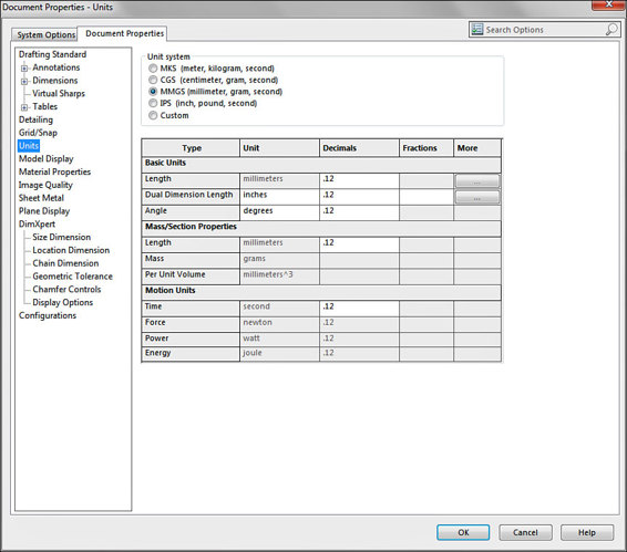
Specifying units in Solidworks.
Scaling in CAD
Once upon a time, when engineering drawings were still created\ with a pencil and paper by drafters, scale was a practical concern. If you wanted to draw a building on a piece of paper that would fit in your briefcase, you obviously couldn’t draw it at its actual size. That’s where scale came in.
In order to draw something large at a practical size, the drafter would draw it at a fixed scale. For a building, he might draw it at a scale of “⅛ inch = 1 foot 0 inches,” meaning that every ⅛ inch on the paper represented 1 foot on the actual building. So a wall 10 feet long would be drawn as 1¼ inches long on paper. The drafter had to take this into account while creating the drawing in order to keep the entire drawing at the correct scale.
However, with the introduction of CAD, this was no longer necessary. In 2D CAD, the drafter could draw the building at a full 1:1 scale and simply rescale it as needed for printing. CAD software could handle rescaling the drawing automatically, so the drafter would only ever have to draw things at a 1:1 scale and let the software do the rest.
But some habits die hard. For people who learned drafting with a pencil and paper, the idea that things had to be scaled tended to stick. So many people continued to carry on with that habit and still drew things at different scales even in CAD programs where it wasn’t necessary to do so. That continues even to this day, despite the fact that it’s entirely unnecessary (and even causes confusion).
Even more bizarrely, that habit has even managed to make its way into 3D modeling in some cases. It’s not common, but some people still make the mistake of defining the dimensions at a scale other than 1:1. It’s important that you learn from the very beginning not to do this, because it’ll cause a lot of headaches if you do.
When you’re using CAD software, always create dimensions at a 1:1 scale. If something is supposed to be 100mm long, give it a dimension of 100mm. This shouldn’t be hard to do, because it’s the natural thing to do anyway if you’re new to CAD and drafting.
If for some reason you need to create a drawing and the model doesn’t fit on the page at 1:1 (or it’s too small), scale the drawing itself instead of the model. If you want to 3D print a miniature version of something you modeled, you can scale it in slicing software (unless it’s intended to always be miniature). Basically, the best way to approach this is to just not think about it and dimension everything at its actual size.
The Least You Need to Know
· CAD software is designed for creating models with specific dimensions, while artistic 3D modeling software is useful for sculpting free-form models.
· Specific CAD commands depend on the software you’re using, but most have similar sets of commands.
· Units are important, and my recommendation is to use the metric system, because it’s what the 3D printing community tends to use.
· Always create all CAD dimensions at a 1:1 scale. If any scaling needs to be done, it should be done separately in the drawing or the slicing software.
All materials on the site are licensed Creative Commons Attribution-Sharealike 3.0 Unported CC BY-SA 3.0 & GNU Free Documentation License (GFDL)
If you are the copyright holder of any material contained on our site and intend to remove it, please contact our site administrator for approval.
© 2016-2026 All site design rights belong to S.Y.A.